WO2005017222A1 - 耐食性に優れた油井用高強度ステンレス鋼管およびその製造方法 - Google Patents
耐食性に優れた油井用高強度ステンレス鋼管およびその製造方法 Download PDFInfo
- Publication number
- WO2005017222A1 WO2005017222A1 PCT/JP2004/011809 JP2004011809W WO2005017222A1 WO 2005017222 A1 WO2005017222 A1 WO 2005017222A1 JP 2004011809 W JP2004011809 W JP 2004011809W WO 2005017222 A1 WO2005017222 A1 WO 2005017222A1
- Authority
- WO
- WIPO (PCT)
- Prior art keywords
- less
- steel pipe
- stainless steel
- strength stainless
- mass
- Prior art date
- Legal status (The legal status is an assumption and is not a legal conclusion. Google has not performed a legal analysis and makes no representation as to the accuracy of the status listed.)
- Ceased
Links
Classifications
-
- C—CHEMISTRY; METALLURGY
- C22—METALLURGY; FERROUS OR NON-FERROUS ALLOYS; TREATMENT OF ALLOYS OR NON-FERROUS METALS
- C22C—ALLOYS
- C22C38/00—Ferrous alloys, e.g. steel alloys
- C22C38/18—Ferrous alloys, e.g. steel alloys containing chromium
- C22C38/40—Ferrous alloys, e.g. steel alloys containing chromium with nickel
- C22C38/42—Ferrous alloys, e.g. steel alloys containing chromium with nickel with copper
-
- C—CHEMISTRY; METALLURGY
- C21—METALLURGY OF IRON
- C21D—MODIFYING THE PHYSICAL STRUCTURE OF FERROUS METALS; GENERAL DEVICES FOR HEAT TREATMENT OF FERROUS OR NON-FERROUS METALS OR ALLOYS; MAKING METAL MALLEABLE, e.g. BY DECARBURISATION OR TEMPERING
- C21D1/00—General methods or devices for heat treatment, e.g. annealing, hardening, quenching or tempering
- C21D1/18—Hardening; Quenching with or without subsequent tempering
- C21D1/25—Hardening, combined with annealing between 300 degrees Celsius and 600 degrees Celsius, i.e. heat refining ("Vergüten")
-
- C—CHEMISTRY; METALLURGY
- C21—METALLURGY OF IRON
- C21D—MODIFYING THE PHYSICAL STRUCTURE OF FERROUS METALS; GENERAL DEVICES FOR HEAT TREATMENT OF FERROUS OR NON-FERROUS METALS OR ALLOYS; MAKING METAL MALLEABLE, e.g. BY DECARBURISATION OR TEMPERING
- C21D6/00—Heat treatment of ferrous alloys
- C21D6/004—Heat treatment of ferrous alloys containing Cr and Ni
-
- C—CHEMISTRY; METALLURGY
- C21—METALLURGY OF IRON
- C21D—MODIFYING THE PHYSICAL STRUCTURE OF FERROUS METALS; GENERAL DEVICES FOR HEAT TREATMENT OF FERROUS OR NON-FERROUS METALS OR ALLOYS; MAKING METAL MALLEABLE, e.g. BY DECARBURISATION OR TEMPERING
- C21D9/00—Heat treatment, e.g. annealing, hardening, quenching or tempering, adapted for particular articles; Furnaces therefor
- C21D9/08—Heat treatment, e.g. annealing, hardening, quenching or tempering, adapted for particular articles; Furnaces therefor for tubular bodies or pipes
-
- C—CHEMISTRY; METALLURGY
- C22—METALLURGY; FERROUS OR NON-FERROUS ALLOYS; TREATMENT OF ALLOYS OR NON-FERROUS METALS
- C22C—ALLOYS
- C22C38/00—Ferrous alloys, e.g. steel alloys
- C22C38/02—Ferrous alloys, e.g. steel alloys containing silicon
-
- C—CHEMISTRY; METALLURGY
- C22—METALLURGY; FERROUS OR NON-FERROUS ALLOYS; TREATMENT OF ALLOYS OR NON-FERROUS METALS
- C22C—ALLOYS
- C22C38/00—Ferrous alloys, e.g. steel alloys
- C22C38/04—Ferrous alloys, e.g. steel alloys containing manganese
-
- C—CHEMISTRY; METALLURGY
- C22—METALLURGY; FERROUS OR NON-FERROUS ALLOYS; TREATMENT OF ALLOYS OR NON-FERROUS METALS
- C22C—ALLOYS
- C22C38/00—Ferrous alloys, e.g. steel alloys
- C22C38/18—Ferrous alloys, e.g. steel alloys containing chromium
- C22C38/40—Ferrous alloys, e.g. steel alloys containing chromium with nickel
- C22C38/44—Ferrous alloys, e.g. steel alloys containing chromium with nickel with molybdenum or tungsten
-
- Y—GENERAL TAGGING OF NEW TECHNOLOGICAL DEVELOPMENTS; GENERAL TAGGING OF CROSS-SECTIONAL TECHNOLOGIES SPANNING OVER SEVERAL SECTIONS OF THE IPC; TECHNICAL SUBJECTS COVERED BY FORMER USPC CROSS-REFERENCE ART COLLECTIONS [XRACs] AND DIGESTS
- Y10—TECHNICAL SUBJECTS COVERED BY FORMER USPC
- Y10S—TECHNICAL SUBJECTS COVERED BY FORMER USPC CROSS-REFERENCE ART COLLECTIONS [XRACs] AND DIGESTS
- Y10S148/00—Metal treatment
- Y10S148/902—Metal treatment having portions of differing metallurgical properties or characteristics
- Y10S148/909—Tube
Definitions
- the present invention relates to a steel pipe for an oil well used for an oil well or gas well of crude oil or natural gas.
- the present invention relates to a high-strength stainless steel pipe for oil wells having excellent corrosion resistance and suitable for oil wells and gas wells in an extremely severe corrosive environment containing carbon dioxide (C 0 2 ) and chlorine ions (C 11).
- “high-strength stainless steel pipe” means a yield strength:
- Patent Literature 1 Patent Literature 2, Patent Literature 3, Patent Literature 4, and Patent Literature 5 describe an improved and improved corrosion resistance of 13% Cr martensitic stainless steel or steel pipe.
- Type martensitic stainless steel or steel pipe has been proposed.
- Patent Document 1 limits C to 0.005% or more and 0.05% or less, Ni: 2.4% or more and 6% or less, and Cu: 0.2% or more and 4% or less, and further adds Mo. 0.5% or more and 3% or less, and further cool the 13% Cr stainless steel tube material of the composition whose Nieq is adjusted to 10.5 or more after hot working at a speed equal to or higher than air cooling, or further (Ac 3 Heat to a temperature above the transformation point + 10 ° C) and below the (Ac 3 transformation point + 200 ° C), or further heat it to a temperature above the A Cl transformation point and below the Ac 3 transformation point, and then air-cool to room temperature
- This is a method for producing a martensitic stainless steel seamless steel pipe excellent in corrosion resistance, which is cooled at the above cooling rate and tempered.
- API- and C95 or higher grade of high strength, martensitic stainless seam combines the corrosion resistance in a deployment, the SCC resistance including 180 ° C or more C
- Patent Document 2 includes C: 0.005% or more, 0.05% or less, N: 0.005% or more, 0.1% or less, Ni: 3.0% or more, 6.0% or less, Cu: 0.5% or more, 3% Mo.
- Mo Hot-worked 13% Cr martensitic stainless steel with a composition adjusted to 0.5% or more and 3% or less and allowed to cool naturally to room temperature, then (A Cl point + 10 ° C) or more, (A (Cl point + 40 ° C) or lower, hold for 30 to 60 minutes, cool to a temperature below the Ms point, temper at a temperature below the A Cl point, temper the structure with martensite and ⁇ phase of 20% by volume or more.
- sulfide stress corrosion resistance is achieved by forming a tempered martensite structure containing 20% by volume or more of 0 / phase. It is said that the crackability is remarkably improved.
- Patent Document 3 is a composition of a martensitic stainless steel containing 10% / o or more and 15% or less of Cr, and limits C to 0.005% or more and 0.05% or less, and Ni: 4.0% or less. % Or more, Cu: 0.5% or more and 3% or less are added, Mo is added 1.0% or more and 3.0% or less, and Nieq is adjusted to 110 or more. Martensite, consisting of a tempered martensite phase and a martensite phase, with the total fraction of the tempered martensite phase and martensite phase being 60% or more and 90% or less, and having excellent corrosion resistance and sulfide stress corrosion cracking resistance. Stainless steel. It says that the corrosion resistance and sulfide stress corrosion cracking resistance in wet carbon dioxide gas environment and wet hydrogen sulfide environment are improved.
- Patent Document 4 contains Cr of more than 15% and 19% or less, C: 0.05% or less, N: 0.1% or less, Ni: 3.5% or more, 8.0% or less, and further Mo: 0.1% or less. % Or more, 4.0% or less, 30Cr + 36Mo + 14Si- 28Ni ⁇ 455 (%), 21Cr + 25Mo + 17Si + 35Ni ⁇ 731 (%) It is said to be an excellent martensitic stainless steel material for oil wells, which results in steel having excellent corrosion resistance even in harsh oil well environments where chloride ions, carbon dioxide gas and trace amounts of hydrogen sulfide gas are present.
- Patent Document 5 contains Cr of 10.0% or more and 17% or less, C: 0.08% or less, N: 0.015% or less, Ni: 6.0% or more, 10.0% or less, Cu: 0.5% or more , 2.0% or less, and Mo: 0.5% or more and 3.0% or less, and the average crystal grain size becomes less than 35% by cold working and annealing at 35% or more.
- a precipitation-hardened martensitic stainless steel with a structure in which precipitates of 5 ⁇ 10 12 / zm or more are suppressed to 6 ⁇ 10 6 Zmm 2 or less and excellent in strength and toughness A technology described in Patent Document 5 According to the publication, it is possible to provide a precipitation-hardened martensitic stainless steel having a high strength and not causing a decrease in toughness by forming a structure having fine crystal grains and a small amount of precipitates.
- Patent Document 1 JP-A-8-120345
- Patent Document 2 JP-A-9-268349
- Patent Document 3 JP-A-10-1755
- Patent Document 4 Patent No. 2814528
- Patent Document 5 Patent No. 3251648 Disclosure of the Invention
- Patent Document 1 Patent Document 2, Patent Document 3, Patent Document 4, an improved 13% Cr martensitic stainless steel pipe manufactured by the technique described in Patent Document 5, C0 2 includes a C1- like
- Patent Document 5 C0 2
- the present invention has been made in view of such circumstances of the related art.
- the present invention is inexpensive, excellent in hot workability, has a high strength yield strength exceeds 654MPa, and C0 2, including C1- etc., in severe corrosive environment of high temperatures up to 230 ° C also excellent in corrosion resistance which exhibits excellent resistance to C0 2 corrosion, and to provide a oil well high strength stainless steel tube and a manufacturing method thereof.
- the present inventors have diligently studied various factors affecting hot workability and corrosion resistance in order to achieve the above-mentioned object.
- the present inventors have studied in more detail the effects of components on hot workability.
- the composition of the steel pipe is
- Figure 1 shows the relationship between the value on the left side of equation (2) and the crack length that occurs on the end face of a 13% Cr stainless steel seamless steel pipe during hot working (that is, when forming a seamless steel pipe).
- Figure 1 It can be seen that cracking can be prevented when the value of the left-hand side value of equation (2) is 8.0 or less, or when the value of the left-hand side value of equation (2) is 11.5 or more, preferably 12.0 or more.
- the value of the left-hand side of equation (2) is 8.0 or less, it corresponds to a region where no flash is generated, and this region is a region of the conventional idea of improving hot workability in which no ferrite phase is generated.
- the present inventors have adjusted the composition so that the left-hand side value of equation (2) is 11.5 or more, and have a completely different idea from the conventional idea, that is, to obtain a structure in which ferrite is relatively generated during pipe making. It has been found for the first time that adoption can significantly improve hot workability.
- Figure 2 shows the length of cracks generated at the end face of a seamless pipe of 13% Cr stainless steel during hot working in relation to the amount of ferrite.
- Fig. 2 according to the conventional concept, when the amount of ferrite is 0% by volume, no cracking occurs, but cracking occurs with the formation of ferrite.
- equation (2) by adjusting the components to satisfy equation (2) and forming a ferrite-martensitic two-phase structure in which an appropriate range of ferrite phase is formed, hot workability is improved and cracking can be prevented.
- the formation of a ferrite-martensite dual phase structure can secure the strength required for an oil country tubular good.
- the present inventors have made it possible to reduce the residual amount of the austenite phase by increasing the Cr content while maintaining a ferrite-martensite two-phase structure containing an appropriate amount of ferrite phase. It has been found that it can be suppressed to a low level and sufficient strength can be secured for oil country tubular goods.
- FIG. 4 The section also shows the relationship between YS and Cr content after heat treatment when the structure is a martensite single phase or martensite-austenite two phase structure. From Fig. 3, it is newly demonstrated that by maintaining the microstructure of ferrite-martensite two-phase structure containing an appropriate amount of ferrite phase and increasing the Cr content, it is possible to secure sufficient strength as an oil country tubular good. Headlined. On the other hand, when the structure is a martensite single phase or a martensite-austenite two-phase structure, the YS decreases as the Cr content increases.
- the present invention has been completed by further study based on the above findings. That is, the gist of the present invention is as follows.
- the composition may further contain, by mass%: Nb: 0.2% or less, Ti: 0.3% or less, Zr: 0.2% or less, W: 3% or less, B: A high-strength stainless steel pipe for oil wells, characterized by having a composition containing one or more selected from 0.01% or less.
- the steel pipe material is heated, pipe-formed by hot working, and after pipe forming, is cooled to room temperature at a cooling rate equal to or higher than air cooling to form a seamless steel pipe having a predetermined size.
- a method for producing a high-strength stainless steel pipe for oil wells characterized in that the composition has a composition containing, in terms of% by mass, 1.0% to 002% and 0.05% or less.
- FIG. 1 is a graph showing the relationship between the crack length and the value on the left side of equation (2).
- FIG. 2 is a graph showing the relationship between the crack length and the amount of ferrite.
- FIG. 3 is a graph showing the relationship between the corrosion rate and the value on the left side of equation (1).
- Figure 4 is a graph showing the effect of the structure on the relationship between the yield strength YS and the Cr content.
- C is an important element related to the strength of martensitic stainless steel.
- the content of 0.005% or more is required. However, if the content exceeds 0.05%, sensitization during tempering due to the inclusion of Ni is increased. Increase.
- C is limited to a range of 0.005% or more and 0.05%. From the viewpoint of corrosion resistance, it is preferable that C is as small as possible, but from the viewpoint of securing strength, it is preferable that C is large. Taking these balances into account, the content is preferably 0.03% or more and 0.05% or less.
- Si 0.05% or more, 0.5% or less
- Si is an element which acts as a deoxidizer, a content exceeding 0.5% 1S to be contained 0.05% or more in the present invention reduces the resistance to C0 2 corrosion, and even decreases the hot workability. For this reason, Si was limited to the range of 0.05% or more and 0.5% or less. Preferably, it is 0.1% or more and 0.3% or less.
- Mn 0.2% or more, 1.8% or less
- Mn is an element that increases the strength, and it is necessary to contain Mn in an amount of 0.2% or more in order to secure the desired strength in the present invention. However, if it exceeds 1.8%, the toughness is adversely affected. Therefore, Mn is limited to the range of 0.2% or more and 1.8% or less. Preferably, the content is 0.2% or more and 1.0% or less. More preferably, it is 0.2% or more and 0.8% or less.
- P is resistant C0 2 corrosion resistance, C0 2 stress corrosion cracking resistance, an element which both deteriorate the pitting corrosion resistance and resistance to sulfide stress corrosion cracking resistance, it is desirable to reduce as much as possible in the present invention The extreme reduction leads to an increase in manufacturing cost.
- Contact Yopi resistance sulfide stress corrosion cracking resistance P is 0.03% or less Limited to Specified. Incidentally, the content is preferably 0.02% or less.
- S is an element that significantly degrades hot workability in the pipe manufacturing process, and it is desirable that it be as small as possible.However, if it is reduced to 0.005% or less, pipe manufacturing can be performed by ordinary processes. Was limited to 0.005% or less. Incidentally, the content is preferably 0.002% or less.
- Cr is an element that forms a protective film to improve corrosion resistance, and particularly contributes to the improvement of O 2 corrosion resistance and C 0 2 stress corrosion cracking resistance.
- the content of 15.5% or more is required from the viewpoint of improving corrosion resistance at high temperatures.
- the content exceeds 18% the hot workability is deteriorated and the strength is reduced. Therefore, in the present invention, Cr is limited to the range of 15.5% or more and 18% or less. In addition, it is preferably 16.5% or more and 18% or less, more preferably 16.6% or more and less than 18%.
- ⁇ is to strengthen the protective film, resistance to C0 2 corrosion resistance, C0 2 stress corrosion cracking resistance, have the effect of enhancing the resistance to pitting resistance and sulfide stress corrosion cracking resistance, and further, the steel by solid solution strengthening It is an element that increases strength. Such an effect is observed when the content is 1.5% or more, but when the content exceeds 5%, the stability of the martensitic structure decreases, and the strength decreases. For this reason, Ni was limited to the range of 1.5% or more and 5% or less. Preferably, it is 2.5% or more and 4.5% or less.
- Mo is an element that increases the resistance to pitting corrosion due to C1—, and the content of 1% or more is required in the present invention. If it is less than 1%, the corrosion resistance in a high-temperature and severely corrosive environment cannot be said to be sufficient. On the other hand, when the content exceeds 3.5%, the strength decreases and the cost becomes high. For this reason, Mo was limited to the range of 1% or more and 3.5% or less. Preferably, it is more than 2% and 3.5% or less.
- V 0.02% or more, 0.2% or less
- V has the effect of increasing strength and improving stress corrosion cracking resistance. Such effects are remarkable when the content is 0.02% or more, but the content exceeds 0.2%. Then, the toughness deteriorates. For this reason, V is limited to 0.02% or more and 0.2% or less. Preferably, the content is 0.02% or more and 0.08% or less.
- N 0.01% or more, 0.15% or less
- N is an element that remarkably improves pitting corrosion resistance.
- N is contained in an amount of 0.01% or more, but if it exceeds 0.15%, various nitrides are formed to deteriorate toughness. For this reason, N was limited to the range of 0.01% or more and 0.15% or less. Preferably, the content is 0.02% or more and 0.08% or less.
- O is limited to 0.006% or less.
- the present invention can further contain Al: 0.002% or more and 0.05% or less.
- A1 is an element having a strong deoxidizing effect. To obtain such an effect, it is desirable that the content of A1 be 0.002% or more. However, if it exceeds 0.05%, the toughness is adversely affected. Therefore, when A1 is contained, the content is preferably limited to a range of 0.002% or more and 0.05% or less. Note that the content is more preferably 0.03% or less. When A1 is not added, less than 0.002% is unavoidable as an inevitable impurity. Limiting A1 to less than about 0.002% has the advantage of significantly improving low-temperature toughness.
- Cu 3.5% or less can be further contained in addition to the above-mentioned respective compositions.
- Cu is an element that strengthens the protective coating, suppresses the intrusion of hydrogen into the steel, and increases the resistance to sulfide stress corrosion cracking. When the content exceeds%, CuS precipitates at the grain boundary, and the hot workability decreases. For this reason, Cu is preferably limited to 3.5% or less. The content is more preferably 0.8% or more and 2.5% or less, and still more preferably 0.5% or more and 1.14% or less.
- Nb 0.2% or less
- Ti 0.3% or less
- Zr 0.2% or less
- W 3% or less
- B 0.01% or less
- Up to one selected Or may contain two or more kinds.
- Nb, Ti, Zr, W, and B are all elements that increase the strength, and can be selectively contained as necessary. Note that Ti, Zr, W, and B are also elements that improve stress corrosion cracking resistance. Such effects are remarkable when the content of ⁇ : 0.03% or more, 1 ⁇ : 0.03% or more, 21 ": 0.03% or more,: 0.2% or more, B: 0.0005% or more.
- Nb: 0.2% If the content exceeds 0.3% for Ti: 0.2%, Zr: 0.2%, W: 3%, and B: 0.01%, toughness deteriorates, so Nb: 0.2% or less, Ti: 0.3% or less, Zr: 0.2% or less , W: preferably 3% or less, B: 0.01% or less.
- Ca 0.01% or less can be further contained.
- Ca has the effect of fixing S as CaS and spheroidizing sulfide inclusions, thereby reducing the lattice strain of the matrix around the inclusions and reducing the hydrogen trapping ability of the inclusions. Having. Such an effect becomes a remarkable when the content is more than 0.0005%, the content exceeding 0.01% causes an increase in CaO, resistance C0 2 corrosion, pitting corrosion resistance is decreased. For this reason, Ca is preferably limited to a range of 0.01% or less.
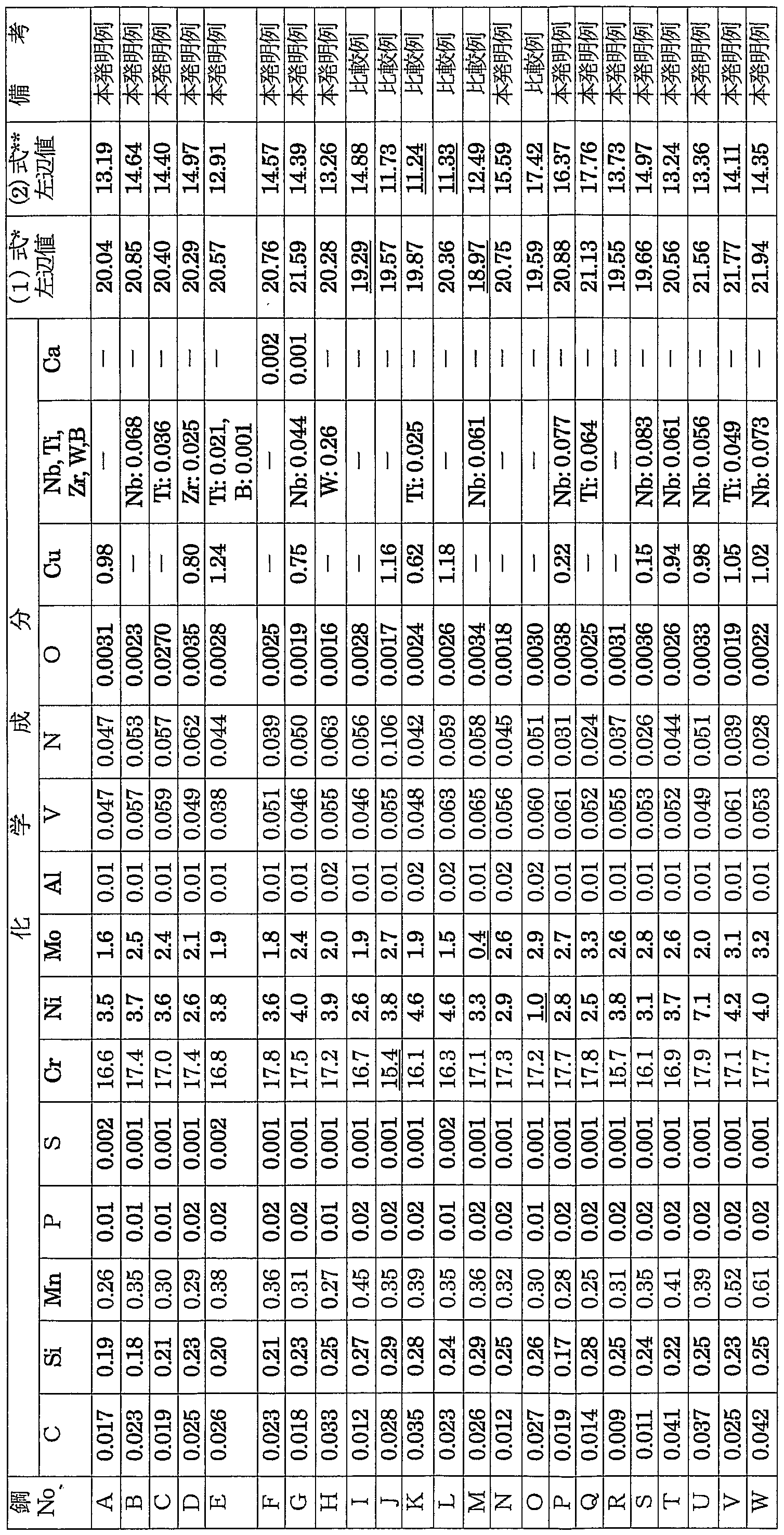
- C0 2 from the viewpoint of improving the corrosion resistance in a high-temperature corrosive environment containing C1 primary, (1) left side value is preferably set to 20.0 or higher.
- the balance other than the above components is Fe and unavoidable impurities.
- the high-strength stainless steel pipe for oil wells of the present invention has a martensite phase as a base phase and a ferrite phase in a volume fraction of 10% or more and 60% or less, preferably more than 10% %.
- the structure of the steel pipe of the present invention is based on a martensite structure in order to ensure high strength.
- the martensite phase is used as the base phase, and the ferrite phase as the second phase is contained in a volume fraction of 10% or more and 60% or less, preferably more than 10% and 60% or less. It is preferable that the organization has the following structure. If the ferrite force S is less than 10% by volume or less than 10% by volume, the intended purpose cannot be achieved. On the other hand, when the ferrite phase is contained in more than 60% by volume, the strength is reduced.
- the volume ratio of the ferrite phase is preferably limited to a range of 10% or more and 60% or less, preferably, more than 10% and 60% or less.
- the content is more preferably 15% or more and 50% by volume.
- a method for manufacturing the steel pipe of the present invention will be described by taking a seamless steel pipe as an example.
- a molten steel having the above-described composition is smelted by a commonly known smelting method such as a converter, an electric furnace, and a vacuum smelting furnace. It is preferable to use a steel pipe material such as a billet.
- these steel pipe materials are heated, and hot-worked and formed using a normal Mannesmann-Plug Mill or Mannesmann-Mandrel Mill manufacturing process to obtain seamless steel pipes of desired dimensions.c
- a structure having a martensite phase as a base phase can be obtained by cooling to room temperature at a cooling rate of at least air cooling after hot working.
- it was cooled at a cooling rate higher than air cooling, reheated to a temperature of 850 ° C or higher, and then reduced to 100 at a cooling rate higher than air cooling. It is preferable to perform a quenching treatment for cooling to preferably room temperature.
- a fine and high toughness martensite structure containing an appropriate amount of ferrite phase can be obtained.
- the heating temperature of the quenching treatment is preferably set to a temperature of 850 ° C or higher.
- the quenched seamless steel pipe is then preferably heated to a temperature of 700 ° C. or less and subjected to a tempering treatment of cooling at a cooling rate equal to or higher than air cooling.
- a tempering treatment of cooling at a cooling rate equal to or higher than air cooling.
- a seamless steel pipe has been described as an example, but the steel pipe of the present invention is not limited to this. It is also possible to manufacture an ERW steel pipe and a UOE steel pipe by using a steel pipe material having a composition within the above-described range of the present invention in accordance with a normal process, and use the steel pipe for an oil well.
- a steel pipe other than a seamless steel pipe obtained according to a normal manufacturing process such as an electric resistance welded steel pipe or a UOE steel pipe, is used for the steel pipe after pipe formation.
- the above-mentioned quenching and tempering treatment reheating to a temperature of 850 ° C or more, then cooling at a cooling rate of air cooling or more to 100 ° C or less, preferably to room temperature, followed by quenching treatment, and then 700 ° C or less, preferably 400 ° C It is preferable to perform a tempering process of heating to a temperature of C or higher and cooling at a cooling rate higher than air cooling.
- the obtained seamless steel pipe was visually inspected for cracks on the inner and outer surfaces while being air-cooled after pipe making, and hot workability was evaluated. Cracks with a length of 5 mm or more at the front and rear end faces of the pipe were considered to have cracks, and the others were not cracked.
- a test piece material was cut out from the obtained seamless steel pipe, heated at 920 ° C for 30 minutes, and then water-cooled (800% or more, average cooling rate up to 500 ° C: 10 ° C / s). Furthermore, tempering treatment was performed at 580 ° C for 30 minutes. From the specimen material thus quenched and tempered, a specimen for tissue observation is collected, the specimen for tissue observation is corroded with aqua regia, and the tissue is imaged with a scanning electron microscope (1000x). Then, using an image analyzer, the tissue fraction (volume%) of the fluoride phase was calculated.
- the retained austenite phase structure fraction was measured by using an X-ray diffraction method.
- a test specimen for measurement is sampled from the quenched and tempered test specimen material, and the diffraction X-ray integrated intensity of the ⁇ (220) plane and ⁇ ; (211) plane is measured by X-ray diffraction.
- Ra crystallographically calculated value of a
- the fraction of the martensite phase is the remainder other than these phases.
- API arc-shaped tensile test specimens were sampled from the quenched and tempered specimens and subjected to tensile tests to determine tensile properties (yield strength YS, tensile strength TS).
- Steel pipe material having the composition shown in Table 1 (Steel No.B, No.S) is pipe-formed by hot working-air cooling after pipe forming, outer diameter 83.8mm X wall thickness 12.7mm (3.3in X wall thickness 0.5in) seamless steel pipe.
- a test piece material was cut out from the obtained seamless steel pipe and subjected to a quenching-tempering process or a tempering process shown in Table 3.
- test piece for structure observation and a test piece for measurement were collected in the same manner as in Example 1 to determine the structure fraction of the fly phase (volume%) and residual austenite.
- the structural fraction of the phase (vol%) and the structural fraction of the martensite phase (vol%) were calculated.
- API arc-shaped tensile test specimens were sampled from the quenched and tempered test specimen material and subjected to a tensile test in the same manner as in Example 1 to obtain tensile properties (yield strength YS, tensile strength TS). I asked. Furthermore, as in Example 1, a corrosion test specimen having a thickness of 3 mm, a width of 30 mm, and a length of 40 mm was manufactured from the quenched and tempered test specimen material by machining, and a corrosion test was performed. And the corrosion rate was determined. Further, as in Example 1, the presence or absence of pitting corrosion on the test piece surface was observed. The evaluation criteria were the same as in Example 1. Table 3 shows the obtained results. Table 3
- yield strength YS has a high strength of at least 654MPa, corrosion speed is also small, without the occurrence of pitting corrosion, at a high temperature of 230 ° C include hot workability and C 0 2 It is a steel pipe with excellent corrosion resistance under severe corrosive environment. If the preferred embodiment of the present invention is out of the preferred range of the present invention, the strength, corrosion resistance and hot workability tend to decrease.
- the obtained seamless steel pipe was visually inspected for the occurrence of cracks on the inner and outer surfaces in the same manner as in Example 1 while cooling (air cooling) after pipe forming, and hot workability was evaluated.
- the evaluation criteria were the same as in Example 1.
- test piece material was cut out from the obtained seamless steel pipe, heated at 900 ° C for 30 minutes, and then cooled with water. Further, tempering treatment was performed at 580 ° C for 30 minutes. From the specimen material thus quenched and tempered, a specimen for observation of structure and a specimen for measurement are collected, and the specimen for observation of structure is corroded with aqua regia and a scanning electron microscope ( The structure was imaged at 1000x), and the structure fraction (vol%) of the ferrite phase was calculated using an image analyzer. Further, test specimens for measurement were sampled from the test specimen material that had been subjected to the quenching and tempering treatment, and the structural fractions (volume%) of the retained austenite phase and the martensite phase were measured in the same manner as in Example 1.
- API arc-shaped tensile test specimens were sampled from the quenched and tempered test specimen material, and tensile tests were performed to determine the tensile properties (yield strength YS, tensile strength TS).
- a V-notch test specimen (thickness: 5 mm) was sampled from the quenched and tempered test specimen material in accordance with JIS Z 2202, and sheared in accordance with JIS Z 2242.
- a ruby impact test was performed to determine the absorbed energy vE- 4Q (J) at -40 ° C.
- a corrosion test specimen having a thickness of 3 mm ⁇ ⁇ ⁇ 30 mm and a length of 40 mm was prepared from the quenched and tempered test specimen material by machining, and a corrosion test was performed.
- only the tempering treatment was performed without performing the quenching treatment.
- the test liquid held in the autoclave: 20% NaCl aqueous solution (liquid Temperature: the 230 ° C, C 0 2 gas atmosphere 100 atm) in the corrosion test piece was immersed was performed between immersion period as 2 weeks.
- the weight of the test piece after the corrosion test was measured, and the corrosion rate calculated from the weight loss before and after the corrosion test was obtained.
- the pitting corrosion resistance was determined by immersing in a solution of 40% CaCl 2 (liquid temperature: 70 ° C) for 24 hours to check for the occurrence of pitting corrosion. Pitting was observed when pitting with a diameter of 0.1 mm or more was observed, and pitting was not observed otherwise. Table 5 shows the obtained results.
- the yield strength YS high strength of 654 MPa or more, low corrosion rate, no pitting, no hot workability and C 0 2 It has excellent corrosion resistance in severe corrosive environments at temperatures as high as 230 ° C.
- excellent corrosion resistance in severe corrosive environment at a high temperature of 230 ° C comprises C 0 2, and later Fukukyo of YS: and 654MPa or more high intensity, one 40 It is a steel pipe with high toughness with an absorbed energy of 50 J or more at ° C.
- the Al content was slightly lower in toughness and pitting occurred, but the degree of the pitting was slightly less than 0.2 mm.
- a stainless steel pipe for oil wells having sufficient corrosion resistance under high temperature and severe corrosive environment including C 0 2 and C 1-and having high strength or even higher toughness can be obtained inexpensively and stably. It can be manufactured and has a remarkable industrial effect. Further, according to the present invention, there is also a 1J point that sufficient strength as an oil well pipe can be obtained only by performing heat treatment after pipe formation.
Landscapes
- Chemical & Material Sciences (AREA)
- Engineering & Computer Science (AREA)
- Materials Engineering (AREA)
- Mechanical Engineering (AREA)
- Metallurgy (AREA)
- Organic Chemistry (AREA)
- Physics & Mathematics (AREA)
- Thermal Sciences (AREA)
- Crystallography & Structural Chemistry (AREA)
- Heat Treatment Of Articles (AREA)
- Heat Treatment Of Steel (AREA)
Description


Claims
Priority Applications (3)
| Application Number | Priority Date | Filing Date | Title |
|---|---|---|---|
| US10/568,154 US7767037B2 (en) | 2003-08-19 | 2004-08-11 | High strength stainless steel pipe for use in oil well having superior corrosion resistance and manufacturing method thereof |
| EP04771770.7A EP1662015B1 (en) | 2003-08-19 | 2004-08-11 | High strength stainless steel pipe excellent in corrosion resistance for use in oil well and method for production thereof |
| BRPI0413626-8B1A BRPI0413626B1 (pt) | 2003-08-19 | 2004-08-11 | tubo de aÇo inoxidÁvel e mÉtodo de fabricaÇço do mesmo |
Applications Claiming Priority (10)
| Application Number | Priority Date | Filing Date | Title |
|---|---|---|---|
| JP2003-295163 | 2003-08-19 | ||
| JP2003295163 | 2003-08-19 | ||
| JP2004016076 | 2004-01-23 | ||
| JP2004-016076 | 2004-01-23 | ||
| JP2004-071640 | 2004-03-12 | ||
| JP2004071640 | 2004-03-12 | ||
| JP2004135974 | 2004-04-30 | ||
| JP2004-135974 | 2004-04-30 | ||
| JP2004-210904 | 2004-07-20 | ||
| JP2004210904A JP5109222B2 (ja) | 2003-08-19 | 2004-07-20 | 耐食性に優れた油井用高強度ステンレス継目無鋼管およびその製造方法 |
Publications (1)
| Publication Number | Publication Date |
|---|---|
| WO2005017222A1 true WO2005017222A1 (ja) | 2005-02-24 |
Family
ID=34199289
Family Applications (1)
| Application Number | Title | Priority Date | Filing Date |
|---|---|---|---|
| PCT/JP2004/011809 Ceased WO2005017222A1 (ja) | 2003-08-19 | 2004-08-11 | 耐食性に優れた油井用高強度ステンレス鋼管およびその製造方法 |
Country Status (5)
| Country | Link |
|---|---|
| US (1) | US7767037B2 (ja) |
| EP (1) | EP1662015B1 (ja) |
| JP (1) | JP5109222B2 (ja) |
| BR (1) | BRPI0413626B1 (ja) |
| WO (1) | WO2005017222A1 (ja) |
Cited By (6)
| Publication number | Priority date | Publication date | Assignee | Title |
|---|---|---|---|---|
| CN100372965C (zh) * | 2005-07-28 | 2008-03-05 | 宝山钢铁股份有限公司 | 耐高温抗腐蚀隔热油管用钢及其制造方法 |
| US8163233B2 (en) | 2006-08-31 | 2012-04-24 | Sumitomo Metal Industries, Ltd. | Martensitic stainless steel for welded structures |
| JP6156609B1 (ja) * | 2016-02-08 | 2017-07-05 | Jfeスチール株式会社 | 油井用高強度ステンレス継目無鋼管およびその製造方法 |
| WO2017168874A1 (ja) * | 2016-03-29 | 2017-10-05 | Jfeスチール株式会社 | 油井用高強度ステンレス継目無鋼管 |
| US10562085B2 (en) | 2013-10-21 | 2020-02-18 | Jfe Steel Corporation | Equipment line for manufacturing heavy-walled steel products |
| CN115491606A (zh) * | 2022-09-28 | 2022-12-20 | 延安嘉盛石油机械有限责任公司 | 一种低Cr含量耐CO2腐蚀油套管及其制备方法 |
Families Citing this family (53)
| Publication number | Priority date | Publication date | Assignee | Title |
|---|---|---|---|---|
| JP4978070B2 (ja) * | 2006-06-16 | 2012-07-18 | Jfeスチール株式会社 | 拡管性に優れる油井用ステンレス鋼管 |
| JP4893196B2 (ja) * | 2006-09-28 | 2012-03-07 | Jfeスチール株式会社 | 高靭性でかつ耐食性に優れた油井用高強度ステンレス鋼管 |
| JP4577457B2 (ja) * | 2008-03-28 | 2010-11-10 | 住友金属工業株式会社 | 油井管に用いられるステンレス鋼 |
| AR073884A1 (es) | 2008-10-30 | 2010-12-09 | Sumitomo Metal Ind | Tubo de acero inoxidable de alta resistencia excelente en resistencia a la fisuracion bajo tension por sulfuros y a la corrosion de gas de acido carbonico en alta temperatura. |
| CN101886228B (zh) * | 2009-05-13 | 2012-02-01 | 中国科学院金属研究所 | 具有高强高韧和高耐腐蚀性能的低碳马氏体时效不锈钢 |
| AR076669A1 (es) | 2009-05-18 | 2011-06-29 | Sumitomo Metal Ind | Acero inoxidable para pozos de petroleo, tubo de acero inoxidable para pozos de petroleo, y metodo de fabricacion de acero inoxidable para pozos de petroleo |
| JP5544197B2 (ja) * | 2010-03-17 | 2014-07-09 | 新日鐵住金ステンレス株式会社 | 溶接部の特性に優れたマルテンサイトステンレス鋼および鋼材 |
| JP4911266B2 (ja) * | 2010-04-28 | 2012-04-04 | 住友金属工業株式会社 | 高強度油井用ステンレス鋼及び高強度油井用ステンレス鋼管 |
| TWI426939B (zh) * | 2011-01-13 | 2014-02-21 | Fusheng Prec L Co Ltd | 高爾夫球桿頭合金及其製造方法 |
| JP5640762B2 (ja) * | 2011-01-20 | 2014-12-17 | Jfeスチール株式会社 | 油井用高強度マルテンサイト系ステンレス継目無鋼管 |
| CN102851607A (zh) * | 2011-06-29 | 2013-01-02 | 宝山钢铁股份有限公司 | 110ksi级高抗CO2腐蚀油套管及其制造方法 |
| CN102534390B (zh) * | 2011-12-15 | 2013-09-04 | 江苏省沙钢钢铁研究院有限公司 | 耐腐蚀螺纹钢筋及其生产方法 |
| TWI440492B (zh) * | 2011-12-30 | 2014-06-11 | Fusheng Prec L Co Ltd | 高爾夫球桿合金 |
| CN104204253B (zh) | 2012-03-26 | 2017-03-29 | 新日铁住金株式会社 | 油井用不锈钢及油井用不锈钢管 |
| UA111115C2 (uk) | 2012-04-02 | 2016-03-25 | Ейкей Стіл Пропертіс, Інк. | Рентабельна феритна нержавіюча сталь |
| JP5488643B2 (ja) * | 2012-05-31 | 2014-05-14 | Jfeスチール株式会社 | 油井管用高強度ステンレス鋼継目無管およびその製造方法 |
| US20130327466A1 (en) * | 2012-06-08 | 2013-12-12 | Pellegrino J. Pisacreta | Insulated tubing |
| KR101982014B1 (ko) * | 2012-06-18 | 2019-05-24 | 제이에프이 스틸 가부시키가이샤 | 후육 고강도 내사우어 라인 파이프, 그의 제조 방법 및 그의 내hic성능의 판정 방법 |
| JP5924256B2 (ja) * | 2012-06-21 | 2016-05-25 | Jfeスチール株式会社 | 耐食性に優れた油井用高強度ステンレス鋼継目無管およびその製造方法 |
| US20150152982A1 (en) * | 2012-07-09 | 2015-06-04 | Jfe Steel Corporation | Thick-walled high-strength sour-resistant line pipe and method for producing same |
| JP5807630B2 (ja) * | 2012-12-12 | 2015-11-10 | Jfeスチール株式会社 | 継目無鋼管の熱処理設備列および高強度ステンレス鋼管の製造方法 |
| JP5967066B2 (ja) | 2012-12-21 | 2016-08-10 | Jfeスチール株式会社 | 耐食性に優れた油井用高強度ステンレス継目無鋼管およびその製造方法 |
| JP5907083B2 (ja) | 2013-01-31 | 2016-04-20 | Jfeスチール株式会社 | 靭性に優れた継目無鋼管の製造方法及び製造設備 |
| EP3042968B1 (en) | 2013-09-04 | 2020-12-09 | JFE Steel Corporation | Method of manufacturing a high-strength stainless steel pipe and high-strength stainless steel pipe |
| JP6171851B2 (ja) | 2013-10-29 | 2017-08-02 | Jfeスチール株式会社 | 継目無鋼管製造用装置列およびそれを利用した油井用高強度ステンレス継目無鋼管の製造方法 |
| BR102014005015A8 (pt) | 2014-02-28 | 2017-12-26 | Villares Metals S/A | aço inoxidável martensítico-ferrítico, produto manufaturado, processo para a produção de peças ou barras forjadas ou laminadas de aço inoxidável martensítico-ferrítico e processo para a produção de tudo sem costura de aço inoxidável martensítico-ferrítico |
| CN106414785B (zh) | 2014-05-21 | 2018-10-09 | 杰富意钢铁株式会社 | 油井用高强度不锈钢无缝钢管及其制造方法 |
| JP6137082B2 (ja) * | 2014-07-31 | 2017-05-31 | Jfeスチール株式会社 | 低温靭性に優れた油井用高強度ステンレス継目無鋼管およびその製造方法 |
| WO2016073218A1 (en) * | 2014-11-04 | 2016-05-12 | Dresser-Rand Company | Corrosion resistant metals and metal compositions |
| JP6315076B2 (ja) * | 2014-11-18 | 2018-04-25 | Jfeスチール株式会社 | 油井用高強度ステンレス継目無鋼管の製造方法 |
| JP6237873B2 (ja) * | 2014-11-19 | 2017-11-29 | Jfeスチール株式会社 | 油井用高強度ステンレス継目無鋼管 |
| US11193179B2 (en) | 2015-01-15 | 2021-12-07 | Jfe Steel Corporation | Seamless stainless steel pipe for oil country tubular goods and method of manufacturing the same |
| JP6206423B2 (ja) * | 2015-01-22 | 2017-10-04 | Jfeスチール株式会社 | 低温靭性に優れた高強度ステンレス厚鋼板およびその製造方法 |
| JP6292142B2 (ja) * | 2015-02-06 | 2018-03-14 | Jfeスチール株式会社 | 油井用高強度ステンレス継目無鋼管の製造方法 |
| WO2016132403A1 (ja) | 2015-02-20 | 2016-08-25 | Jfeスチール株式会社 | 高強度継目無厚肉鋼管およびその製造方法 |
| JP6341128B2 (ja) * | 2015-03-30 | 2018-06-13 | Jfeスチール株式会社 | 油井用薄肉高強度ステンレス継目無鋼管の製造方法 |
| EP3112492A1 (en) | 2015-06-29 | 2017-01-04 | Vallourec Oil And Gas France | Corrosion resistant steel, method for producing said steel and its use thereof |
| MX2018000331A (es) | 2015-07-10 | 2018-03-14 | Jfe Steel Corp | Tuberia de acero inoxidable sin costura de alta resistencia y metodo de fabricacion de tuberia de acero inoxidable sin costura de alta resistencia. |
| BR112017020184A2 (ja) * | 2015-08-04 | 2018-06-12 | Nippon Steel & Sumitomo Metal Corporation | Stainless steel and stainless steel material for oil wells |
| JP6578810B2 (ja) * | 2015-08-19 | 2019-09-25 | 日本製鉄株式会社 | 油井管 |
| EP3404120B1 (en) | 2016-01-13 | 2020-03-04 | Nippon Steel Corporation | Method for manufacturing stainless steel pipe for oil wells and stainless steel pipe for oil wells |
| JP6304460B1 (ja) * | 2016-07-27 | 2018-04-04 | Jfeスチール株式会社 | 油井用高強度ステンレス継目無鋼管およびその製造方法 |
| US11268161B2 (en) | 2017-01-13 | 2022-03-08 | Jfe Steel Corporation | High strength seamless stainless steel pipe and method for producing same |
| WO2018155041A1 (ja) | 2017-02-24 | 2018-08-30 | Jfeスチール株式会社 | 油井用高強度ステンレス継目無鋼管およびその製造方法 |
| US11286548B2 (en) | 2017-08-15 | 2022-03-29 | Jfe Steel Corporation | High-strength stainless steel seamless pipe for oil country tubular goods, and method for manufacturing same |
| KR102123665B1 (ko) * | 2018-10-23 | 2020-06-18 | 주식회사 포스코 | 클램프용 고강도 페라이트계 스테인리스강 및 그 제조방법 |
| JP7385487B2 (ja) * | 2020-02-10 | 2023-11-22 | 日鉄ステンレス株式会社 | ステンレス鋼材及び拡散接合体 |
| JP7255559B2 (ja) * | 2020-06-24 | 2023-04-11 | Jfeスチール株式会社 | ステンレス鋼粉末、ステンレス鋼部材およびステンレス鋼部材の製造方法 |
| JP7226571B2 (ja) * | 2020-07-06 | 2023-02-21 | Jfeスチール株式会社 | ステンレス継目無鋼管およびその製造方法 |
| EP4293133A4 (en) * | 2021-04-21 | 2025-07-30 | Jfe Steel Corp | STAINLESS STEEL PIPE AND ITS MANUFACTURING METHOD |
| CN114941109A (zh) * | 2022-06-30 | 2022-08-26 | 宁波康颖健康科技有限公司 | 钣金用耐蚀钢板 |
| CN116121664B (zh) * | 2022-12-13 | 2025-04-08 | 钢铁研究总院有限公司 | 一种高耐蚀高韧性经济型钢及其制备方法 |
| CN116145051B (zh) * | 2022-12-13 | 2024-11-12 | 钢铁研究总院有限公司 | 一种高耐蚀经济型油井管钢及其制备方法 |
Citations (5)
| Publication number | Priority date | Publication date | Assignee | Title |
|---|---|---|---|---|
| JPH0375337A (ja) * | 1989-08-16 | 1991-03-29 | Nippon Steel Corp | 高強度かつ耐食性の優れたマルテンサイト系ステンレス鋼 |
| JP2001179485A (ja) * | 1999-12-27 | 2001-07-03 | Sumitomo Metal Ind Ltd | マルテンサイト系ステンレス溶接鋼管およびその製造方法 |
| JP2001279392A (ja) * | 2000-03-30 | 2001-10-10 | Sumitomo Metal Ind Ltd | マルテンサイト系ステンレス鋼および製造方法 |
| JP2002004009A (ja) * | 2000-06-19 | 2002-01-09 | Kawasaki Steel Corp | 油井用高強度マルテンサイト系ステンレス鋼管およびその製造方法 |
| JP2002129278A (ja) * | 2000-10-20 | 2002-05-09 | Sumitomo Metal Ind Ltd | 高Cr鋼鋳片および継目無鋼管 |
Family Cites Families (13)
| Publication number | Priority date | Publication date | Assignee | Title |
|---|---|---|---|---|
| JP2814528B2 (ja) | 1989-03-15 | 1998-10-22 | 住友金属工業株式会社 | 油井用マルテンサイト系ステンレス鋼材とその製造方法 |
| JP2742949B2 (ja) * | 1989-08-16 | 1998-04-22 | 新日本製鐵株式会社 | 耐食性の優れたマルテンサイト系ステンレス鋼およびその製造方法 |
| JP3251648B2 (ja) | 1992-07-14 | 2002-01-28 | 日新製鋼株式会社 | 析出硬化型マルテンサイト系ステンレス鋼及びその製造方法 |
| JP2944856B2 (ja) * | 1993-06-14 | 1999-09-06 | 山陽特殊製鋼株式会社 | 冷間加工性および耐孔食性に優れた析出硬化型ステンレス鋼 |
| JP3814836B2 (ja) | 1994-08-23 | 2006-08-30 | 住友金属工業株式会社 | 耐食性に優れたマルテンサイト系ステンレス鋼継目無鋼管の製造法 |
| JP3444008B2 (ja) | 1995-03-10 | 2003-09-08 | 住友金属工業株式会社 | 耐炭酸ガス腐食性及び耐硫化物応力腐食割れ性の優れたマルテンサイトステンレス鋼 |
| JP3489333B2 (ja) | 1996-01-29 | 2004-01-19 | 住友金属工業株式会社 | 耐硫化物応力割れ性に優れたマルテンサイト系ステンレス鋼 |
| JPH101755A (ja) | 1996-04-15 | 1998-01-06 | Nippon Steel Corp | 耐食性、耐硫化物応力腐食割れに優れたマルテンサイトステンレス鋼及びその製造方法 |
| EP1179380B1 (en) * | 1999-08-06 | 2009-10-14 | Sumitomo Metal Industries, Ltd. | Martensite stainless steel welded steel pipe |
| JP2002060910A (ja) * | 2000-08-11 | 2002-02-28 | Sumitomo Metal Ind Ltd | 高Cr溶接鋼管 |
| JP4867088B2 (ja) * | 2001-06-21 | 2012-02-01 | 住友金属工業株式会社 | 高Cr系継目無鋼管の製造方法 |
| DE60231279D1 (de) | 2001-08-29 | 2009-04-09 | Jfe Steel Corp | Verfahren zum Herstellen von nahtlosen Rohren aus hochfester, hochzäher, martensitischer Rostfreistahl |
| EP1514950B1 (en) * | 2002-06-19 | 2011-09-28 | JFE Steel Corporation | Stainless-steel pipe for oil well and process for producing the same |
-
2004
- 2004-07-20 JP JP2004210904A patent/JP5109222B2/ja not_active Expired - Lifetime
- 2004-08-11 BR BRPI0413626-8B1A patent/BRPI0413626B1/pt not_active IP Right Cessation
- 2004-08-11 EP EP04771770.7A patent/EP1662015B1/en not_active Expired - Lifetime
- 2004-08-11 WO PCT/JP2004/011809 patent/WO2005017222A1/ja not_active Ceased
- 2004-08-11 US US10/568,154 patent/US7767037B2/en not_active Expired - Lifetime
Patent Citations (5)
| Publication number | Priority date | Publication date | Assignee | Title |
|---|---|---|---|---|
| JPH0375337A (ja) * | 1989-08-16 | 1991-03-29 | Nippon Steel Corp | 高強度かつ耐食性の優れたマルテンサイト系ステンレス鋼 |
| JP2001179485A (ja) * | 1999-12-27 | 2001-07-03 | Sumitomo Metal Ind Ltd | マルテンサイト系ステンレス溶接鋼管およびその製造方法 |
| JP2001279392A (ja) * | 2000-03-30 | 2001-10-10 | Sumitomo Metal Ind Ltd | マルテンサイト系ステンレス鋼および製造方法 |
| JP2002004009A (ja) * | 2000-06-19 | 2002-01-09 | Kawasaki Steel Corp | 油井用高強度マルテンサイト系ステンレス鋼管およびその製造方法 |
| JP2002129278A (ja) * | 2000-10-20 | 2002-05-09 | Sumitomo Metal Ind Ltd | 高Cr鋼鋳片および継目無鋼管 |
Cited By (11)
| Publication number | Priority date | Publication date | Assignee | Title |
|---|---|---|---|---|
| CN100372965C (zh) * | 2005-07-28 | 2008-03-05 | 宝山钢铁股份有限公司 | 耐高温抗腐蚀隔热油管用钢及其制造方法 |
| US8163233B2 (en) | 2006-08-31 | 2012-04-24 | Sumitomo Metal Industries, Ltd. | Martensitic stainless steel for welded structures |
| US10562085B2 (en) | 2013-10-21 | 2020-02-18 | Jfe Steel Corporation | Equipment line for manufacturing heavy-walled steel products |
| JP6156609B1 (ja) * | 2016-02-08 | 2017-07-05 | Jfeスチール株式会社 | 油井用高強度ステンレス継目無鋼管およびその製造方法 |
| WO2017138050A1 (ja) * | 2016-02-08 | 2017-08-17 | Jfeスチール株式会社 | 油井用高強度ステンレス継目無鋼管およびその製造方法 |
| US11085095B2 (en) | 2016-02-08 | 2021-08-10 | Jfe Steel Corporation | High-strength seamless stainless steel pipe for oil country tubular goods and method of manufacturing high-strength seamless stainless steel pipe |
| WO2017168874A1 (ja) * | 2016-03-29 | 2017-10-05 | Jfeスチール株式会社 | 油井用高強度ステンレス継目無鋼管 |
| JPWO2017168874A1 (ja) * | 2016-03-29 | 2018-04-05 | Jfeスチール株式会社 | 油井用高強度ステンレス継目無鋼管 |
| US11414719B2 (en) | 2016-03-29 | 2022-08-16 | Jfe Steel Corporation | High strength stainless steel seamless pipe for oil country tubular goods |
| CN115491606A (zh) * | 2022-09-28 | 2022-12-20 | 延安嘉盛石油机械有限责任公司 | 一种低Cr含量耐CO2腐蚀油套管及其制备方法 |
| CN115491606B (zh) * | 2022-09-28 | 2023-08-25 | 延安嘉盛石油机械有限责任公司 | 一种低Cr含量耐CO2腐蚀油套管及其制备方法 |
Also Published As
| Publication number | Publication date |
|---|---|
| EP1662015B1 (en) | 2018-10-24 |
| BRPI0413626A (pt) | 2006-10-17 |
| US20060243354A1 (en) | 2006-11-02 |
| JP5109222B2 (ja) | 2012-12-26 |
| EP1662015A1 (en) | 2006-05-31 |
| BRPI0413626B1 (pt) | 2013-07-16 |
| JP2005336595A (ja) | 2005-12-08 |
| US7767037B2 (en) | 2010-08-03 |
| EP1662015A4 (en) | 2006-11-08 |
Similar Documents
| Publication | Publication Date | Title |
|---|---|---|
| WO2005017222A1 (ja) | 耐食性に優れた油井用高強度ステンレス鋼管およびその製造方法 | |
| JP4363327B2 (ja) | 油井用ステンレス鋼管およびその製造方法 | |
| US10240221B2 (en) | Stainless steel seamless pipe for oil well use and method for manufacturing the same | |
| RU2459884C1 (ru) | Труба из высокопрочной нержавеющей стали с превосходной устойчивостью к растрескиванию под действием напряжений в сульфидсодержащей среде и устойчивостью к высокотемпературной газовой коррозии под действием диоксида углерода | |
| JP5145793B2 (ja) | 油井管用マルテンサイト系ステンレス継目無鋼管およびその製造方法 | |
| JP4893196B2 (ja) | 高靭性でかつ耐食性に優れた油井用高強度ステンレス鋼管 | |
| JP5092204B2 (ja) | 拡管性に優れる油井用ステンレス鋼管 | |
| JP5446335B2 (ja) | 油井用高強度ステンレス鋼管の評価方法 | |
| JP4462005B2 (ja) | 耐食性に優れたラインパイプ用高強度ステンレス鋼管およびその製造方法 | |
| WO2005042793A1 (ja) | 耐食性に優れたラインパイプ用高強度ステンレス鋼管およびその製造方法 | |
| CN115298343A (zh) | 不锈钢无缝钢管和不锈钢无缝钢管的制造方法 | |
| JP4978073B2 (ja) | 耐食性に優れる油井用高靭性超高強度ステンレス鋼管およびその製造方法 | |
| JP5499575B2 (ja) | 油井管用マルテンサイト系ステンレス継目無鋼管およびその製造方法 | |
| JP7315097B2 (ja) | 油井用高強度ステンレス継目無鋼管およびその製造方法 | |
| CN100497705C (zh) | 耐腐蚀性优良的管线管用高强度不锈钢管及其制造方法 | |
| WO2015033518A1 (ja) | 高強度ステンレス鋼管の製造方法および高強度ステンレス鋼管 | |
| KR20130133030A (ko) | 2상 스테인리스강 | |
| WO2016079920A1 (ja) | 油井用高強度ステンレス継目無鋼管 | |
| JP4470617B2 (ja) | 耐炭酸ガス腐食性に優れる油井用高強度ステンレス鋼管 | |
| JP4449174B2 (ja) | 油井用高強度マルテンサイト系ステンレス鋼管の製造方法 | |
| JP4978070B2 (ja) | 拡管性に優れる油井用ステンレス鋼管 | |
| JP3539250B2 (ja) | 高耐応力腐食割れ性を有する655Nmm−2級低C高Cr合金油井管およびその製造方法 | |
| JP7347714B1 (ja) | 油井用高強度ステンレス継目無鋼管 | |
| WO2006117926A1 (ja) | 拡管性に優れる油井管用ステンレス鋼管 | |
| JP5040215B2 (ja) | 拡管性に優れる油井用ステンレス鋼管 |
Legal Events
| Date | Code | Title | Description |
|---|---|---|---|
| WWE | Wipo information: entry into national phase |
Ref document number: 200480023557.1 Country of ref document: CN |
|
| AK | Designated states |
Kind code of ref document: A1 Designated state(s): AE AG AL AM AT AU AZ BA BB BG BR BW BY BZ CA CH CN CO CR CU CZ DE DK DM DZ EC EE EG ES FI GB GD GE GH GM HR HU ID IL IN IS KE KG KP KR KZ LC LK LR LS LT LU LV MA MD MG MK MN MW MX MZ NA NI NO NZ OM PG PH PL PT RO RU SC SD SE SG SK SL SY TJ TM TN TR TT TZ UA UG US UZ VC VN YU ZA ZM ZW |
|
| AL | Designated countries for regional patents |
Kind code of ref document: A1 Designated state(s): BW GH GM KE LS MW MZ NA SD SL SZ TZ UG ZM ZW AM AZ BY KG KZ MD RU TJ TM AT BE BG CH CY CZ DE DK EE ES FI FR GB GR HU IE IT LU MC NL PL PT RO SE SI SK TR BF BJ CF CG CI CM GA GN GQ GW ML MR NE SN TD TG |
|
| 121 | Ep: the epo has been informed by wipo that ep was designated in this application | ||
| WWE | Wipo information: entry into national phase |
Ref document number: 2004771770 Country of ref document: EP |
|
| WWE | Wipo information: entry into national phase |
Ref document number: 2006243354 Country of ref document: US Ref document number: 10568154 Country of ref document: US |
|
| WWP | Wipo information: published in national office |
Ref document number: 2004771770 Country of ref document: EP |
|
| ENP | Entry into the national phase |
Ref document number: PI0413626 Country of ref document: BR |
|
| WWP | Wipo information: published in national office |
Ref document number: 10568154 Country of ref document: US |