WO2006013696A1 - ロッカーアーム用転がり軸受 - Google Patents
ロッカーアーム用転がり軸受 Download PDFInfo
- Publication number
- WO2006013696A1 WO2006013696A1 PCT/JP2005/012455 JP2005012455W WO2006013696A1 WO 2006013696 A1 WO2006013696 A1 WO 2006013696A1 JP 2005012455 W JP2005012455 W JP 2005012455W WO 2006013696 A1 WO2006013696 A1 WO 2006013696A1
- Authority
- WO
- WIPO (PCT)
- Prior art keywords
- rocker arm
- inner ring
- rolling
- rolling bearing
- bearing
- Prior art date
- Legal status (The legal status is an assumption and is not a legal conclusion. Google has not performed a legal analysis and makes no representation as to the accuracy of the status listed.)
- Ceased
Links
Classifications
-
- F—MECHANICAL ENGINEERING; LIGHTING; HEATING; WEAPONS; BLASTING
- F01—MACHINES OR ENGINES IN GENERAL; ENGINE PLANTS IN GENERAL; STEAM ENGINES
- F01L—CYCLICALLY OPERATING VALVES FOR MACHINES OR ENGINES
- F01L1/00—Valve-gear or valve arrangements, e.g. lift-valve gear
- F01L1/12—Transmitting gear between valve drive and valve
- F01L1/18—Rocking arms or levers
- F01L1/181—Centre pivot rocking arms
-
- F—MECHANICAL ENGINEERING; LIGHTING; HEATING; WEAPONS; BLASTING
- F01—MACHINES OR ENGINES IN GENERAL; ENGINE PLANTS IN GENERAL; STEAM ENGINES
- F01L—CYCLICALLY OPERATING VALVES FOR MACHINES OR ENGINES
- F01L1/00—Valve-gear or valve arrangements, e.g. lift-valve gear
- F01L1/12—Transmitting gear between valve drive and valve
- F01L1/18—Rocking arms or levers
- F01L1/185—Overhead end-pivot rocking arms
-
- F—MECHANICAL ENGINEERING; LIGHTING; HEATING; WEAPONS; BLASTING
- F01—MACHINES OR ENGINES IN GENERAL; ENGINE PLANTS IN GENERAL; STEAM ENGINES
- F01L—CYCLICALLY OPERATING VALVES FOR MACHINES OR ENGINES
- F01L1/00—Valve-gear or valve arrangements, e.g. lift-valve gear
- F01L1/20—Adjusting or compensating clearance
-
- F—MECHANICAL ENGINEERING; LIGHTING; HEATING; WEAPONS; BLASTING
- F16—ENGINEERING ELEMENTS AND UNITS; GENERAL MEASURES FOR PRODUCING AND MAINTAINING EFFECTIVE FUNCTIONING OF MACHINES OR INSTALLATIONS; THERMAL INSULATION IN GENERAL
- F16C—SHAFTS; FLEXIBLE SHAFTS; ELEMENTS OR CRANKSHAFT MECHANISMS; ROTARY BODIES OTHER THAN GEARING ELEMENTS; BEARINGS
- F16C19/00—Bearings with rolling contact, for exclusively rotary movement
- F16C19/22—Bearings with rolling contact, for exclusively rotary movement with bearing rollers essentially of the same size in one or more circular rows, e.g. needle bearings
- F16C19/44—Needle bearings
- F16C19/46—Needle bearings with one row or needles
- F16C19/466—Needle bearings with one row or needles comprising needle rollers and an outer ring, i.e. subunit without inner ring
-
- F—MECHANICAL ENGINEERING; LIGHTING; HEATING; WEAPONS; BLASTING
- F16—ENGINEERING ELEMENTS AND UNITS; GENERAL MEASURES FOR PRODUCING AND MAINTAINING EFFECTIVE FUNCTIONING OF MACHINES OR INSTALLATIONS; THERMAL INSULATION IN GENERAL
- F16C—SHAFTS; FLEXIBLE SHAFTS; ELEMENTS OR CRANKSHAFT MECHANISMS; ROTARY BODIES OTHER THAN GEARING ELEMENTS; BEARINGS
- F16C3/00—Shafts; Axles; Cranks; Eccentrics
- F16C3/02—Shafts; Axles
-
- F—MECHANICAL ENGINEERING; LIGHTING; HEATING; WEAPONS; BLASTING
- F16—ENGINEERING ELEMENTS AND UNITS; GENERAL MEASURES FOR PRODUCING AND MAINTAINING EFFECTIVE FUNCTIONING OF MACHINES OR INSTALLATIONS; THERMAL INSULATION IN GENERAL
- F16C—SHAFTS; FLEXIBLE SHAFTS; ELEMENTS OR CRANKSHAFT MECHANISMS; ROTARY BODIES OTHER THAN GEARING ELEMENTS; BEARINGS
- F16C33/00—Parts of bearings; Special methods for making bearings or parts thereof
- F16C33/30—Parts of ball or roller bearings
- F16C33/34—Rollers; Needles
-
- F—MECHANICAL ENGINEERING; LIGHTING; HEATING; WEAPONS; BLASTING
- F16—ENGINEERING ELEMENTS AND UNITS; GENERAL MEASURES FOR PRODUCING AND MAINTAINING EFFECTIVE FUNCTIONING OF MACHINES OR INSTALLATIONS; THERMAL INSULATION IN GENERAL
- F16C—SHAFTS; FLEXIBLE SHAFTS; ELEMENTS OR CRANKSHAFT MECHANISMS; ROTARY BODIES OTHER THAN GEARING ELEMENTS; BEARINGS
- F16C33/00—Parts of bearings; Special methods for making bearings or parts thereof
- F16C33/30—Parts of ball or roller bearings
- F16C33/58—Raceways; Race rings
- F16C33/62—Selection of substances
-
- F—MECHANICAL ENGINEERING; LIGHTING; HEATING; WEAPONS; BLASTING
- F16—ENGINEERING ELEMENTS AND UNITS; GENERAL MEASURES FOR PRODUCING AND MAINTAINING EFFECTIVE FUNCTIONING OF MACHINES OR INSTALLATIONS; THERMAL INSULATION IN GENERAL
- F16C—SHAFTS; FLEXIBLE SHAFTS; ELEMENTS OR CRANKSHAFT MECHANISMS; ROTARY BODIES OTHER THAN GEARING ELEMENTS; BEARINGS
- F16C2202/00—Solid materials defined by their properties
- F16C2202/02—Mechanical properties
- F16C2202/04—Hardness
-
- F—MECHANICAL ENGINEERING; LIGHTING; HEATING; WEAPONS; BLASTING
- F16—ENGINEERING ELEMENTS AND UNITS; GENERAL MEASURES FOR PRODUCING AND MAINTAINING EFFECTIVE FUNCTIONING OF MACHINES OR INSTALLATIONS; THERMAL INSULATION IN GENERAL
- F16C—SHAFTS; FLEXIBLE SHAFTS; ELEMENTS OR CRANKSHAFT MECHANISMS; ROTARY BODIES OTHER THAN GEARING ELEMENTS; BEARINGS
- F16C2360/00—Engines or pumps
- F16C2360/18—Camshafts
-
- Y—GENERAL TAGGING OF NEW TECHNOLOGICAL DEVELOPMENTS; GENERAL TAGGING OF CROSS-SECTIONAL TECHNOLOGIES SPANNING OVER SEVERAL SECTIONS OF THE IPC; TECHNICAL SUBJECTS COVERED BY FORMER USPC CROSS-REFERENCE ART COLLECTIONS [XRACs] AND DIGESTS
- Y10—TECHNICAL SUBJECTS COVERED BY FORMER USPC
- Y10T—TECHNICAL SUBJECTS COVERED BY FORMER US CLASSIFICATION
- Y10T29/00—Metal working
- Y10T29/49—Method of mechanical manufacture
- Y10T29/49229—Prime mover or fluid pump making
- Y10T29/49295—Push rod or rocker arm making
-
- Y—GENERAL TAGGING OF NEW TECHNOLOGICAL DEVELOPMENTS; GENERAL TAGGING OF CROSS-SECTIONAL TECHNOLOGIES SPANNING OVER SEVERAL SECTIONS OF THE IPC; TECHNICAL SUBJECTS COVERED BY FORMER USPC CROSS-REFERENCE ART COLLECTIONS [XRACs] AND DIGESTS
- Y10—TECHNICAL SUBJECTS COVERED BY FORMER USPC
- Y10T—TECHNICAL SUBJECTS COVERED BY FORMER US CLASSIFICATION
- Y10T74/00—Machine element or mechanism
- Y10T74/20—Control lever and linkage systems
- Y10T74/20576—Elements
- Y10T74/20882—Rocker arms
Definitions
- the present invention relates to a rocker arm rolling bearing used for opening and closing an engine engine intake valve and an exhaust valve, and more particularly to a rocker arm rolling bearing with a longer life. It is.
- Some recent rolling bearings are full-roller types, such as those used for rocker arms used to open and close engine intake valves and exhaust valves. Many bearings are used.
- the rollers are likely to be skewed due to interference between the rollers or due to the force that the roller position is not controlled smoothly.
- the lubricating oil is not supplied well into the bearing, the situation where the lubrication conditions are poor is likely to occur.
- sliding heat generation and local surface pressure increase occur, and surface damage (peeling, smearing, surface-origin type delamination) and internal-origin type delamination are likely to occur despite a large load capacity in the calculation. I helped.
- a bearing component in which shot-peening is applied to the bearing ring of the bearing component to improve the rolling fatigue life, and a reinforcing layer, a retained austenite-containing layer, and a hardened hardened layer are sequentially provided inside the surface force. — 168022 (Patent Document 1)).
- Patent Document 2 Japanese Patent Laid-Open No. 2001-0655
- a cam follower device (a rocker arm bearing) in which the hardness of the outer diameter of the cam follower outer ring is the same as that of the counterpart cam and the inner ring has a higher hardness than the outer diameter.
- the maximum compressive stress of the surface layer at a depth of 0 to 50 / zm from the surface is 50 to: LlOkgfZmm 2
- the hardness was set to HV830 to 960, retained austenite was set to 7% or more, the average wavelength of surface roughness was set to 25 ⁇ m or less, and these were achieved by shot peening (Patent No. 3125434 (Patent Document 5)) .
- a bearing for a cam follower device for a valve operating mechanism of an engine (bearer for a rocker arm) having a calculated service life of 1000 hours or more at a rated engine speed (Japanese Patent Laid-Open No. 2000-038907) No. (Patent Document 6)).
- a cam follower shaft (a rocker arm bearing component) made of tool steel, etc., which is lower than the tempering temperature and made hard by ion nitriding and ion plating at a temperature (Japanese Patent Laid-Open No. 10 110720 (Patent Document) 9)).
- Patent Document 15 describes a method of making an inner ring into a hollow cylindrical shape (pipe).
- reducing the size of the bearing is limited by the shape of the cam and the lift amount for opening and closing the valve. Therefore, the diameter cannot be simply reduced, and downsizing in the width (axis) direction is the mainstream. Therefore, as a lightweight and compact method of bearings, the mainstream is the hollow cylinder of the inner ring and the size reduction in the width direction.
- the applicant has so far improved the heat treatment technology to improve the outer ring, rollers, and the inner ring that is fixed to the rocker arm by press-fitting, pinning, etc. (other than caulking) (the inner ring is entirely cured).
- the inner ring that is fixed to the rocker arm by performing the crimping process increases the machining process. Therefore, a hollow cylindrical shape is not used, but a solid cylindrical shape is used, and the end face is crimped.
- a hollow cylindrical shape is not used, but a solid cylindrical shape is used, and the end face is crimped.
- only the rolling surfaces of the rollers, which are rolling elements, are surface hardened by induction heat treatment. This is disclosed in, for example, Japanese Patent Application Laid-Open No. 62-007908 (Patent Document 16) and Japanese Patent Application Laid-Open No. 5-321616 (Patent Document 17).
- a hollow cylindrical inner ring has a curved shape as compared to a solid cylindrical inner ring. Since the bending stress increases, there is a method for preventing this damage by making this bending stress 15 kgfZmm 2 or less (see Japanese Patent Laid-Open No. 2000-038906). However, this method imposes shape restrictions and hinders the light weight and compactness of the bearing.
- Patent Document 1 Japanese Patent Laid-Open No. 2-168022
- Patent Document 2 Japanese Patent Laid-Open No. 2001-065576
- Patent Document 3 JP-A-3-199716
- Patent Document 4 Japanese Utility Model Publication No. 3-119508
- Patent Document 5 Japanese Patent No. 3125434
- Patent Document 6 Japanese Patent Laid-Open No. 2000-038907
- Patent Document 7 Japanese Patent Laid-Open No. 10-47334
- Patent Document 8 JP-A-10-103339
- Patent Document 9 Japanese Patent Laid-Open No. 10-110720
- Patent Document 10 Japanese Patent Laid-Open No. 2000-038906
- Patent Document 11 Japanese Unexamined Patent Publication No. 2002-031212
- Patent Document 12 Japanese Utility Model Publication No. 63-185917
- Patent Document 13 Japanese Unexamined Patent Application Publication No. 2002-194438
- Patent Document 14 Japanese Patent Application Laid-Open No. 5-179350
- Patent Document 15 U.S. Pat.No. 4,727,832
- Patent Document 16 Japanese Patent Laid-Open No. 62-007908
- Patent Document 17 Japanese Patent Laid-Open No. 5-321616
- Patent Document 18 JP-A-3-031503
- Patent Document 19 Japanese Utility Model Publication No. 3-0663703
- a first object of the present invention is to provide a rocker arm rolling bearing with a long life.
- the second object of the present invention is used to open and close an engine intake valve and an exhaust valve, and in addition to rolling fatigue life under conditions of high speed, large load, and low viscosity of lubricating oil.
- Another object of the present invention is to provide a rolling bearing for a rocker arm that has a long surface damage life against surface damage caused by metal contact.
- the third object of the present invention is to suppress a reduction in life while achieving compactness. It is to provide a rolling bearing for a rocker arm.
- the fourth object of the present invention is to provide a lightweight 'compact type bearing having a hollow cylindrical inner ring in a bearing used for a rocker arm used for opening and closing an engine intake valve or an exhaust valve.
- the object is to provide a rocker arm rolling bearing that meets the demands of dredging and has improved crack fatigue strength and rolling fatigue life.
- the rocker arm rolling bearing according to the first aspect of the present invention includes an outer ring that is in contact with the cam shaft of the engine in a rolling force S, an inner ring that is positioned inside the outer ring and is fixed to the rocker arm, and an outer ring.
- a rocker arm rolling bearing having a plurality of rolling elements interposed between the inner ring and the inner ring, at least one member of the outer ring, the inner ring, and the rolling element has a nitrogen-enriched layer, and The grain size number of the austenite grains is in the range exceeding 10 and the surface hardness Hv is 653 or more.
- the rolling fatigue life can be greatly improved by making the austenite grains of the above members finer as the grain size number exceeds 10. If the austenite grain size number is 10 or less, the rolling fatigue life is not greatly improved. Normally, it should be 11 or higher.
- the average crystal grain size may be 6 m or less. Although the austenite grain size is preferably finer, it is usually difficult to obtain a grain size number exceeding # 13.
- the austenite grain size may be obtained by a normal method defined in JIS, or may be converted by obtaining an average grain size corresponding to the grain size number by the intercept method or the like.
- the austenite grain size number may be satisfied in the nitrogen-enriched layer.
- the above-mentioned standard for austenite grain refinement is also satisfied in the steel body inside the carbonitrided layer.
- the austenite crystal grains are austenite crystals that have undergone phase transformation during quenching and heating. This refers to the grains that remain in the past history even after being transformed into martensite by cooling.
- the “inner ring” includes a solid shaft and a hollow shaft.
- the rolling fatigue life can be greatly improved. If the surface hardness Hv is less than 653, the service life will be reduced, especially under conditions of contamination.
- the surface hardness Hv is 720 or more and 800 or less. Higher surface hardness Hv is more desirable, but if the surface hardness Hv exceeds 800, carbides can become large and can quickly become a source of stress concentration.
- the rocker arm described above is rotatably attached to a rotating shaft located between one end and the other end, and an end of an engine opening / closing valve is attached to one end.
- the rocker arm may have a bifurcated inner ring support at the other end, and the inner ring of the rocker arm rolling bearing of the present invention may be fixed to the bifurcated inner ring support.
- a rocker arm rolling bearing S is provided between one end of the rocker arm and the other end, and the inner ring is formed in the inner ring hole extending between the two side walls of the rocker arm.
- the end of the valve for opening and closing the engine may be in contact with one end of the rocker arm, and the pivot may be in contact with the other end of the rocker arm.
- the rocker arm includes a rocker arm main body and an interlocking rod that transmits stress from the cam shaft, and the rocker arm main body has one end and the other end of the rocker arm main body.
- the end of the valve for engine opening / closing comes into contact with one end of the rocker arm main body, and the interlocking rod is attached to one end of the rocker arm main body.
- One end may abut and the inner ring of the rolling bearing of the present invention may be fixed to the other end of the interlocking rod.
- rocker arms (al), (a2), and (a3) above have a common force in that the driving force from the cam is transmitted to the engine valve, and the structure is different. Now we can handle each! / Speak.
- rocker arm rolling bearing may be a full-roller-one-dollar bearing.
- the rolling bearing for a rocker arm corresponds to an inner ring fixed to a rocker arm that adjusts intake and exhaust by being interposed between an engine noble and a force drum.
- a shaft an outer ring positioned outside the inner ring and in contact with the cam, and a plurality of rolling elements positioned between the outer ring and the inner ring.
- At least one member of the outer ring, the inner ring, and the rolling element has a nitrogen-enriched layer, the austenite grain size number in the nitrogen-enriched layer is in the range exceeding 10th, and the nitrogen-enriched layer residual austenite amount is in the range of 11 to 25 volume 0/0 at the surface 50 m of the rolling surface after grinding.
- the shaft corresponding to the inner ring may be a solid shaft or a hollow shaft.
- the axis corresponding to these inner rings is expressed as an inner ring.
- the austenite crystal grains of the outer ring, inner ring or rolling element do not change in the surface layer portion where the nitrogen-enriched layer exists or in the inside thereof. Therefore, the target position of the above-mentioned range of crystal grain number is the surface layer and Z or inside.
- the austenite crystal grain is a crystal grain based on the trace of the austenite crystal grain boundary immediately before quenching after the quenching treatment.
- the particle size number can be measured according to JIS standards and the like as described in the embodiment.
- the retained austenite when the amount of retained austenite is 11% by volume or more, the retained austenite is martensite even when stress and Z or strain that cause local damage are applied. Compressive stress is generated so that damage does not occur due to volume expansion due to transformation. For this reason, the surface damage life is improved. When the amount of retained austenite is less than 11%, the improvement of the surface damage life is small. On the other hand, if the amount of retained austenite is more than 25% by volume, the amount of retained austenite is no different from that of normal carbonitriding, and the volume expansion associated with the transformation from retained austenite to martensite becomes excessive. This is not preferable because the dimensional change increases. For this reason, the retained austenite is 11 vol% to 25 vol%. A more preferred range is 15% to 25% by volume.
- Residual austenite amount 11 vol% to 25 vol 0/0 or 15 vol% to 25 vol 0/0 is the value of the surface layer portion of the rolling surface of Ken Kezunochi.
- the nitrogen content in the nitrogen-enriched layer is preferably in the range of 0.1 wt% to 0.7 wt%.
- the nitrogen-enriched layer is a layer with an increased nitrogen content formed on the outer ring, the inner ring or the surface of the rolling element, for example, by treatment such as carbonitriding, nitriding, or nitriding. Can be formed.
- the nitrogen content in the nitrogen-enriched layer is preferably in the range of 0.1% by weight to 0.7% by weight. When the nitrogen content is less than 0.1% by weight, the effect on the formation of retained austenite and the increase in hardness is small, and in particular, the surface damage life is reduced.
- the nitrogen content of the nitrogen-enriched layer is a value in the surface layer portion of the rolling surface after grinding. Nitrogen content can be rephrased as nitrogen content.
- the rocker arm is rotatably supported by a rotating shaft located between one end and the other end, and one end is bifurcated.
- the inner ring is fixed to the bifurcated inner ring support, and the end of the valve of the engine is in contact with the other end.
- a rocker arm rolling bearing includes an outer ring that is in rolling contact with a cam shaft of an engine, an inner ring that is positioned inside the outer ring and is fixed to the rocker arm, and an outer ring.
- a rocker arm rolling bearing including a plurality of rolling elements interposed between the inner ring and the inner ring, all of the outer ring, the inner ring, and the rolling element have a nitrogen-enriched layer.
- the austenite grains of the nitrogen-enriched layer in at least one of the inner ring and rolling element is in the range exceeding 10 and the amount of retained austenite of the member is 11 volume% or more and 25 volume% or less, and the nitrogen content of the member is 0.1 mass% or more and 0.7 mass% It is as follows.
- the austenite crystal grains do not change either in the surface layer portion where the nitrogen-enriched layer exists or in the inside thereof. Therefore, the target positions in the above range of the grain size number are the surface layer and the inside.
- the austenite crystal grains are austenite crystal grains transformed during quenching heating, and this is what remains as a past history even after transformation to martensite by cooling. Say.
- the amount of retained austenite is less than 11% volume, the surface damage life tends to be greatly reduced.
- the amount of retained austenite is more than 25% by volume, the amount of retained austenite is a normal carbonitriding process. As the difference disappears, the aging change becomes worse.
- the amount of retained austenite is a value at a surface layer of 50 ⁇ m of the rolling surface after grinding.
- the bending strength of martensite ⁇ (211) and retained austenite ⁇ (220) by X-ray diffraction method. Can be measured by comparison.
- it can be measured by obtaining the magnetic repulsive force using a magnetic balance etc. by utilizing the fact that the austenite phase is a non-magnetic material and the ferrite phase is a ferromagnetic material.
- it can be easily measured using a commercially available measuring device.
- the nitrogen-enriched layer is a layer having an increased nitrogen content formed on the surface layer, and can be formed by a process such as carbonitriding, nitriding, or nitriding. If the nitrogen content of the nitrogen-enriched layer is less than 0.1% by mass, the effect will be lost, especially the surface damage life will be reduced. When the nitrogen content is more than 0.7% by mass, voids called voids are formed, and the residual austenite becomes too much to harden, resulting in a short life.
- the nitrogen content of the nitrogen-enriched layer is the value at the surface layer of 50 ⁇ m of the rolling surface after grinding. For example, it can be measured with EPMA (Electron Probe Micro-Analysis). it can.
- the rocker arm is attached to a rocker arm shaft positioned between one end and the other end, and the end of the engine opening / closing valve abuts on one end.
- the rocker arm may have a bifurcated inner ring support at the other end, and the inner ring of the rocker arm rolling bearing of the present invention may be fixed to the bifurcated inner ring support.
- the rocker arm rolling bearing of the present invention is provided between one end of the rocker arm and the other end, and the inner ring hole between the two side walls of the rocker arm is provided in the inner ring hole.
- the wheel may be fixed, the end of the opening / closing valve of the engine may be in contact with one end of the rocker arm, and the pivot may be in contact with the other end of the rocker arm.
- the rocker arm includes a rocker arm main body and an interlocking rod that transmits stress from the cam shaft, and the rocker arm main body has one end and the other end of the rocker arm main body.
- the end of the valve for engine opening / closing comes into contact with one end of the rocker arm body, and one end of the interlocking rod is attached to one end of the rocker arm body.
- the end part abuts and the inner ring of the rocker arm rolling bearing of the present invention may be fixed to the other end part of the interlocking rod.
- the “inner ring” includes a solid shaft and a hollow shaft.
- a rocker arm rolling bearing includes an outer ring that is in contact with the cam shaft of the engine in a rolling force S, an inner ring that is positioned inside the outer ring and is fixed to the rocker arm, and an outer ring and an inner ring.
- a rocker arm rolling bearing including a plurality of rolling elements interposed between the outer ring, the inner ring, and the rolling elements, at least one member has a nitrogen-enriched layer and has a nitrogen-enriched layer
- the austenite grain size number of the member is in the range exceeding 10 and the area ratio of the spherical carbonized carbide of the member having the nitrogen-enriched layer is 10% or more.
- the austenite crystal grain size may be obtained by a normal method prescribed in JIS, or the average grain size corresponding to the crystal grain size number may be obtained by a section method or the like and converted. Good.
- the austenite grain size number may be satisfied in the carbonitriding layer.
- the above-mentioned standard for austenite grain refinement is also satisfied in the steel body inside the carbonitrided layer.
- the austenite crystal grains are crystal grains of austenite that has undergone phase transformation during quenching heating, and this remains as a past history even after transformation to martensite by cooling.
- the “inner ring” includes a solid shaft and a hollow shaft.
- the rolling fatigue life can be greatly improved by setting the area ratio of the spheroidized carbide of the member having the nitrogen-enriched layer to 10% or more. If the area ratio of the spherical carbide is less than 10%, the rolling fatigue life is not greatly improved, so the range should be 10% or more.
- Spherical ⁇ The area ratio of carbide is preferably as large as possible, but usually when the area ratio exceeds 25%, the toughness of the material deteriorates due to carbide enlargement and agglomeration, so it is preferably in the range of 10% to 25%.
- the rocker arm is rotatably attached to a rotating shaft located between one end and the other end, and an end of an engine opening / closing valve is attached to one end.
- the rocker arm may have a bifurcated inner ring support at the other end, and the inner ring of the rocker arm rolling bearing of the present invention may be fixed to the bifurcated inner ring support.
- a rocker arm rolling bearing S is provided between one end of the rocker arm and the other end, and the inner ring is formed in the inner ring hole extending between the two side walls of the rocker arm.
- the end of the valve for opening and closing the engine may be in contact with one end of the rocker arm, and the pivot may be in contact with the other end of the rocker arm.
- the rocker arm includes a rocker arm main body and an interlocking rod that transmits stress from the cam shaft, and the rocker arm main body has one end and the other end of the rocker arm main body.
- the end of the valve for engine opening / closing comes into contact with one end of the rocker arm main body, and the interlocking rod is attached to one end of the rocker arm main body.
- One end may abut and the inner ring of the rolling bearing of the present invention may be fixed to the other end of the interlocking rod.
- rocker arms (dl), (d2), and (d3) described above use the driving force from the cam to The common force in terms of transmitting to the lube
- the structure is different, so that it can handle different engine types.
- rocker arm rolling bearing may be a full-roller type single-roller bearing.
- a rocker arm rolling bearing includes a plurality of outer rings that are in rolling contact with an engine camshaft, an inner ring located inside the outer ring, and a plurality of intermediate rings interposed between the outer ring and the inner ring.
- the inner ring is made of steel containing 0.5% by mass or more of carbon, has a hollow cylindrical shape, and has a hardness of HV200 or more and HV300 or less at the end face. And having a hardened layer over the entire radial direction from the rolling surface to the inner diameter surface of the inner ring on which the rolling element rolls.
- the hardened layer is formed on the entire surface in the radial direction up to the inner diameter of the rolling surface of the inner ring on which the rolling element rolls. Static crack strength and crack fatigue strength can be improved.
- the inner ring has a hollow cylindrical shape, the rolling bearing can be made lighter and more compact.
- the amount of carbon in the steel constituting the inner ring is hardened to an appropriate hardness (HV653 or higher) by performing high-frequency heat treatment on the outer diameter surface of the inner ring, which is the rolling surface of the roller, which is a rolling element. 0.5% by mass or more is required.
- the hardness of the end face of the inner ring is within the range of HV200 or more and HV300 or less that can be caulked.
- the grain number number of the austenite crystal grains in the surface layer portion of the rolling surface of the inner ring is in the range exceeding 10, and the grain size of the austenite crystal grains The number is the value at the surface layer of 50 ⁇ m of the rolling surface after grinding.
- the rolling fatigue life can be greatly improved by the fact that the austenite grain size number exceeds 10 and the austenite grain size is fine. If the austenite grain size number is 10 or less, the crack fatigue strength and rolling fatigue life are not greatly improved. Usually 11 or higher.
- the austenite crystal grains are austenite immediately after quenching and immediately before quenching.
- the trace of the night crystal grain boundary remains, and the crystal grain is based on the trace.
- the inner ring has a nitrogen-enriched layer in the surface layer portion.
- the amount of retained austenite of the inner ring rolling surface surface layer is in the range of 11% by volume to 40% by volume, and the amount of retained austenite is ground. It is the value at the surface layer 50 m of the later rolling surface.
- the amount of retained austenite is about 11% by volume, the surface damage life tends to decrease, and when it is less than 11% by volume, it tends to decrease further.
- the amount of retained austenite is more than 40% by volume, the surface hardness is lowered and the rolling fatigue life is deteriorated.
- the nitrogen content in the nitrogen-enriched layer is preferably in the range of 0.1% by mass to 0.7% by mass, and the nitrogen content thereof Is the value at the surface layer of 50 m of the rolling surface after grinding.
- the nitrogen-enriched layer is a layer having an increased nitrogen content formed on the surface layer of the inner ring, and can be formed by, for example, carbonitriding, nitriding, nitriding, or the like. If the nitrogen content is less than 0.1% by mass, the effect is not obtained, and the surface damage life is particularly reduced. When the nitrogen content is more than 0.7% by mass, voids called voids are formed, or the amount of retained austenite becomes too large to cause hardness, resulting in a short life.
- the surface hardness of the rolling surface of the inner ring is preferably HV653 or more.
- the surface hardness is as high as HV653 or more, the rolling fatigue life can be greatly improved. If the surface hardness is less than HV653, the rolling fatigue life will not be greatly improved, but it will worsen.
- the surface hardness range is HV720 to HV800. Higher surface hardness is desirable, but it is usually difficult to obtain surface hardness exceeding HV900.
- the area ratio of the spherical carbide in the nitrogen-enriched layer on the surface of the rolling surface of the inner ring is 10% or more.
- the area ratio of carbide is the value at the surface layer of 50 m of the rolling surface after grinding.
- the rolling fatigue life can be greatly improved. If the area ratio of spherical carbide is less than 10%, the rolling fatigue life is large. It will not be improved, so it should be 10% or more.
- the larger the area ratio of spherical carbide the better, but usually, if an area ratio exceeding 25% is obtained, the toughness of the material deteriorates due to coarsening and agglomeration of the carbide, so it is preferably in the range of 10% to 25%.
- the area ratio of the spheroidized carbide is a value at the surface layer of 50 m of the rolling surface after grinding, and can be observed with an optical microscope (400 times) after corrosion using a picric alcohol solution (picral).
- the rocker arm is attached to a rocker arm shaft positioned between one end and the other end, and one of the rocker arms
- An end portion is provided with a bifurcated inner ring support portion, the other end portion is in contact with an end portion of an engine opening / closing valve, and an inner ring is fixed to the bifurcated inner ring support portion.
- a pivot is in contact with one end of the rocker arm, so that one end of the rocker arm and the other end A rolling bearing is provided between them, and the end of the valve for opening and closing the engine is in contact with the other end.
- the rocker arm is attached to a rocker arm shaft positioned between one end and the other end, and one of the rocker arms
- One end of the interlocking rod that transmits the force from the camshaft is in contact with the end, and the end of the valve for opening and closing the engine is in contact with the other end.
- the other end of the interlocking rod Is provided with a rolling bearing.
- each aspect of the above (el), (e2), and (e3) is common in that the driving force from the cam is transmitted to the valve of the engine, but the structure is different, and different engine types are used. Can be adapted to each.
- the rolling bearing is preferably a full-roller type. -One dollar bearing.
- the rolling bearing for rocker arm according to the first aspect of the present invention has austenite grains refined to have a grain size number exceeding 10, and further has a surface hardness Hv of 653 or more, so that rolling fatigue The service life is greatly improved, and excellent cracking strength and aging resistance can be obtained.
- the rolling bearing for rocker arm according to the fourth aspect of the present invention has fine austenite grains so that the particle size number exceeds 10, and the area ratio of the spheroidized carbide is 10% or more.
- the rolling fatigue life is greatly improved, and excellent cracking resistance and aging resistance can be obtained.
- the surface force of the rolling surface on which the rolling elements of the inner ring roll is formed by forming a hardened layer over the entire radial direction up to the inner diameter. Crack strength and crack fatigue strength can be improved. In addition, since the inner ring has a hollow cylindrical shape, the rolling bearing can be made lighter and more compact.
- the austenite crystals are refined to a particle size number exceeding 10, the amount of retained austenite is moderate, the surface hardness is appropriate, and the area of spheroidized carbide Because of the high rate, both the normal load-dependent rolling fatigue life and the surface damage life due to metal contact caused by slippage and oil film breakage can be improved.
- FIG. 1 is a schematic front view showing a usage state of a rocker arm rolling bearing according to Embodiment 1 of the present invention.
- FIG. 2 is a cross-sectional view taken along line II-II in FIG.
- FIG. 3 Usage of other rocker arm rolling bearings according to the first embodiment of the present invention. It is a schematic front view shown.
- FIG. 4 is a schematic front view showing a usage state of still another rocker arm rolling bearing according to the first embodiment of the present invention.
- FIG. 5 is an enlarged view of a portion including the rocker arm rolling bearing of FIG.
- ⁇ 6 A diagram for explaining a heat treatment method in Embodiment 1 of the present invention.
- FIG. 7 is a diagram for explaining a modification of the heat treatment method according to the first embodiment of the present invention.
- This is a diagram showing the microstructure of bearing parts, especially austenite grains.
- (A) is a bearing part of the present invention example, and (b) is a conventional bearing part.
- FIG. 8 (a) is a diagram illustrating an austenite grain boundary illustrated in FIG. 8 (a), and (b) is a diagram illustrating an austenite grain boundary illustrated in FIG. 8 (b).
- FIG. 11 is a cross-sectional perspective view for describing a pattern of a hardened layer in the second embodiment of the present invention.
- FIG. 12 A diagram illustrating a heat treatment method according to the second embodiment of the present invention.
- FIG. 13 A diagram for explaining another heat treatment method according to the second embodiment of the present invention.
- FIG. 14 is a diagram in which specific conditions are added to the heat pattern HI in FIG.
- FIG. 15 is a diagram in which specific conditions are added to the heat pattern H2 of FIG.
- FIG. 16 is a view showing a rolling fatigue testing machine for rotating an outer ring.
- FIG. 17 is a view showing a test piece of a static crushing strength test (measurement of a breaking stress value).
- FIG. 18 is a schematic view of a rolling fatigue life tester.
- (A) is a front view and
- (b) is a side view.
- ⁇ 19] A view showing a specimen for a static fracture toughness test.
- ⁇ 22 It is a front view showing a main part of the peeling life test apparatus.
- FIG. 23 is a cross-sectional view taken along the line ⁇ - ⁇ in FIG.
- FIG. 1 is a schematic front view showing a usage state of a rocker arm rolling bearing according to Embodiment 1 of the present invention
- FIG. 2 is a cross-sectional view taken along line II-II in FIG.
- the rocker arm 1 which is a rotating member has a rocker arm shaft 5 via a bearing metal or the like at a central portion located between one end la and the other end lb. It is supported by the rotation itself.
- the rocker arm 1 swings around the rocker arm shaft 5.
- An adjustment screw 7 is screwed into one end lb of the rocker arm 1.
- the adjustment screw 7 is fixed by a lock nut 8 and is in contact with an upper end portion 9a of an air supply valve or exhaust valve (engine opening / closing valve) 9 of the internal combustion engine at the lower end thereof.
- This valve 9 is biased by the repulsive force of the spring 10.
- the rocker arm 1 integrally has an inner ring support portion (roller support portion) 14 formed in a bifurcated shape at the other end la.
- the roller shaft hole formed in the bifurcated inner ring support portion 14 is fixed by force caulking, press-fitting, or retaining rings of the roller shaft 2 corresponding to the inner ring.
- the roller shaft 2 has a hollow cylindrical shape.
- a roller 4 constituting an outer ring is supported at the center of the outer peripheral surface of the roller shaft 2 through a plurality of rollers 3 as rolling elements. That is, a plurality of rollers 3 are interposed between the roller shaft 2 and the roller 4.
- the bifurcated roller support portion 14 includes a roller shaft 2 corresponding to an inner ring, a roller 3 serving as a rolling element, and a roller 4 corresponding to an outer ring, and a roller type roller bearing (needle bearing) 50. Is arranged.
- the axial direction of roller 3 is arranged parallel to the axis of roller shaft 2. It is.
- the outer peripheral surface of the roller 4 is in contact with the cam surface of the cam 6 provided on the cam shaft by the biasing force of the spring 10. In other words, the cam 6 and the roller 4 are in rolling contact.
- the rocker arm rolling bearing 50 is a full roller bearing that does not use a cage, and includes a roller shaft 2, a plurality of rollers 3, and a roller 4.
- the rocker arm rolling bearing 50 plays a role of reducing friction between the rocker arm 1 and the cam 6 and improving wear resistance. Since the rocker arm rolling bearing 50 rotates with a force S that does not come into contact with the cam 6, the pressing force and impact force of the cam 6 act on the roller 4.
- FIG. 3 is a schematic front view showing a usage state of another rocker arm rolling bearing according to Embodiment 1 of the present invention.
- rocker arm rolling bearing 50 is provided between one end lb of rocker arm 1 and the other end la.
- a roller hole (not shown) as an inner ring hole is formed between the two side walls lc of the rocker arm 1.
- the roller shaft 2 is fixed to the roller hole.
- the roller shaft 2 has a hollow cylindrical shape, and both ends thereof are inserted into a roller shaft hole (not shown) formed in each of the side walls on both sides of the rocker arm 1 so as to be force-processed. This is fixed.
- a roller 4 is supported at the center of the outer diameter surface of the roller shaft 2 through rollers 3 so as to be rotatable.
- the axial direction of the roller 3 is arranged parallel to the axis of the roller shaft 2.
- the outer diameter surface of the roller 4 is brought into contact with the force surface of the cam 6 provided on the cam shaft by the biasing force of the spring 10.
- one end lb of the rocker arm 1 is in contact with the upper end 9a of the engine opening / closing nove 9 and the other end la of the rocker arm 1 is provided with a pivot hole 15. ing.
- the pivot hole 15 abuts on a pivot (not shown).
- the rocker arm 1 provided with the pivot hole 15 is biased by a spring 10 in a predetermined direction around the pivot. The driving force transmitted from the cam 6 is received by the roller 4, and the valve 9 is moved against the biasing force of the spring 10.
- FIG. 4 is a schematic front view showing a usage state of still another rocker arm rolling bearing according to Embodiment 1 of the present invention.
- FIG. 5 is an enlarged view of a portion including the rocker arm rolling bearing of FIG.
- rocker arm 1 has rocker arm body 11 and interlocking bar 16 that transmits stress from cam 6 force.
- a rocker arm shaft (rotating shaft) 5 is arranged between one end lib of the rocker arm main body 11 and the other end 11a, that is, at the center of the rocker arm main body 11, and around the rocker arm main body. 11 rotates.
- the upper end 9a of the valve 9 is in contact with one end lib of the rocker arm body 11, and the valve 9 is biased by the spring force of the spring 10. Further, the upper end portion 16 b of the interlocking rod 16 is in contact with the other end portion 11 a of the rocker arm body 11.
- An adjustment screw 7 is attached to the other end 11 a of the rocker arm body 11.
- the adjustment screw 7 has a function of adjusting the contact position between the rocker arm body 11 and the interlocking rod 16.
- the roller shaft 2 of the rocker arm rolling bearing 50 is attached to the hollow bearing mounting portion 16a located at the lower end portion of the interlocking rod 16 by the mounting member 17! /.
- the cam 6 abuts against the roller 4 of the rocker arm rolling bearing 50 and transmits the driving force to the interlocking rod 16.
- the rolling bearing 50 includes a roller shaft 2 corresponding to an inner ring, a roller 3 serving as a rolling element, and a roller 4 corresponding to an outer ring.
- the roller shaft 2 has a hollow cylindrical shape. Both ends of the roller shaft 2 are fixed to the mounting member 17 by crimping.
- a roller 4 is supported rotatably at the center of the outer peripheral diameter of the roller shaft 2 via a roller 3. The axial direction of the roller 3 is arranged parallel to the axis of the roller shaft 2.
- At least one member of the roller 3, the roller shaft 2 and the outer ring roller 4 is subjected to a heat treatment of a low-temperature secondary quenching method to be described. And fine austenite grains.
- at least one member of the roller shaft 2, which is the inner ring, the roller 3, which is the rolling element, and the roller 4, which is the outer ring in FIGS. Induction hardening and austenite grain size of 11 or more (according to CFIS standard) and ultra-fine and hardness HV65 3 or more.
- the roller 3 is subjected to a heat treatment of a low-temperature secondary quenching method to be described below.
- the grain size number of the austenite crystal grains is in the range exceeding # 10
- the amount of residual austenite of the nitrogen-enriched layer is in the range of 11% to 25% by volume in the surface layer portion of the rolling surface after grinding. It has been.
- the roller 4, the roller shaft 2, and the roller 3 all have a nitrogen-enriched layer. Further, the nitrogen-enriched layer of at least one of the roller shaft 2 and the roller 3 is subjected to a low-temperature secondary quenching heat treatment described below on at least one of the roller shaft 2 and the roller 3.
- the austenite grain size number is in the range exceeding # 10, the retained austenite content is 11 volume% or more and 25 volume% or less, and the nitrogen content is 0.1 mass% or more and 0.7 mass% or less. Become.
- the grain size number of the austenite crystal grains is set to a range exceeding 10 and the area ratio of the spherical carbonized carbide is set to 10% or more.
- FIG. 6 is a diagram for explaining a heat treatment method according to Embodiment 1 of the present invention.
- FIG. 7 is a diagram for explaining a modification of the heat treatment method according to Embodiment 1 of the present invention.
- Fig. 6 is a heat treatment pattern showing the method of primary quenching and secondary quenching, and Fig. 7 shows that the material is cooled below the A transformation point temperature during quenching, and then re-heated and finally quenched.
- treatment ⁇ diffuses carbon and nitrogen into the steel substrate and dissolves carbon.
- the above-mentioned heat treatment is normally quenched, that is, after the carbonitriding treatment, it is tempered once as it is. It is possible to improve the cracking strength and reduce the aging rate of dimensional change while carbonitriding the surface layer portion rather than adding it. As described above, according to the above heat treatment method, it is possible to obtain a microstructure in which the grain size of austenite crystal grains is less than half of the conventional one.
- the bearing parts subjected to the above heat treatment have a long rolling fatigue characteristic, can improve the cracking strength, and can also reduce the aging rate of dimensional change.
- FIG. 8 is a diagram showing the microstructure of bearing parts, particularly austenite grains.
- FIG. 8 (a) shows a bearing component of the present invention example
- FIG. 8 (b) shows a conventional bearing component. That is, FIG. 8 (a) shows the austenite grain size of the bearing steel to which the heat treatment pattern shown in FIG. 6 is applied.
- Fig. 8 (b) shows the austenite grain size of the bearing steel by the conventional heat treatment method.
- FIGS. 9 (a) and 9 (b) are diagrams showing austenite grain boundaries illustrated in FIGS. 8 (a) and 8 (b).
- the conventional austenite grain size is a number of 10 or less in the JIS standard grain size number, and according to the heat treatment method of the present invention, the 12th fine grain can be obtained. Further, the average particle diameter in FIG. 8 (a) was 5.6 m as a result of measurement by the intercept method.
- inner ring 2 of rocker arm rolling bearing 50 of the present embodiment is made of steel containing 0.5% by mass or more of carbon, has a hollow cylindrical shape, and has an end face It has a hardness of HV200 or more and HV300 or less.
- the inner ring 2 of each rolling bearing 50 has a radial direction from the rolling surface surface of the inner ring 2 on which the roller (rolling element) 3 rolls to the inner diameter surface 2c. It has a hardened layer as a whole. It is preferable that such a hardened layer is formed over the entire circumference of the inner ring 2 in the circumferential direction.
- the pattern of this hardened layer disclosed in Japanese Patent Application Laid-Open No. 2000-38906 is that the hardened layer 2a is only the rolling surface surface layer portion of the outer diameter surface 2b of the inner ring 2 as shown in FIG.
- the surface layer portion of the inner diameter surface 2c and the surface layer portion of the end surface 2d are uncured layers.
- the inner ring 2 in which the hardened layer 2a and the uncured layer are mixed has a lower strength than the inner ring 2 in which the whole is the hardened layer 2a. Since it is easily deformed, a large tensile stress is generated at the center of the inner surface 2c.
- the surface layer portion of the inner diameter surface 2c is an uncured layer and has a lower fatigue strength than the cured layer 2a. Cracks are generated by the action of tensile stress, often leading to inner ring damage.
- the inner surface 2c from the rolling surface surface layer portion of the outer surface 2b of the inner ring 2 The entire radial direction is the hardened layer 2a, and the portion of the uncured layer is only near the surface layer portion of the end face 2d.
- the hardened layer 2a has a larger area than the inner ring 2 shown in FIG. Even when the load is repeatedly applied, the central portion of the inner diameter surface 2c is the hardened layer 2a, and the fatigue strength is high, so that the occurrence of cracks can be prevented and the possibility of causing damage to the inner ring 2 is reduced.
- the hardened layer pattern of Fig. 11 (b) is more advantageous in strength than Fig. 11 (a) because the region of the hardened layer 2a on the inner diameter surface 2c is wide.
- the inner diameter surface 2c is wide against the tensile stress generated by repeated loading, but it prevents cracks from occurring across the area. It is also advantageous when receiving an unbalanced load due to the unstable behavior of the rocker arm 1.
- the hardness of the hardened layer 2a is HV653 or higher, and the hardness of the unhardened layer including the end face 2d of the inner ring 2 is HV200 or higher and HV300 or lower.
- An intermediate layer (hardness HV300 or more and HV653 or less) exists between the cured layer 2a and the uncured layer.
- the inner ring 2 has a nitrogen-enriched layer in the surface layer portion, and the surface layer portion is subjected to induction hardening, and the austenite grain size is in the range exceeding # 10 and is ultrafine (according to the CFIS standard). It is preferable.
- the surface hardness of the rolling surface of the inner ring 2 is HV653 or more. Further, since the surface layer portion of the inner ring 2 has been induction hardened, it is preferable that the amount of retained austenite occupies 11 volume% or more and 40 volume% or less. Further, the nitrogen content in the nitrogen-enriched layer is preferably in the range of 0.1% by mass or more and 0.7% by mass or less. These amounts of retained austenite and nitrogen are the values at the surface layer of 50 m of the rolling surface after grinding. As a result, surface damage and internal origin-type delamination are less likely to occur in the surface layer portion, while other portions are easily caulked due to their low hardness. For this reason, although not shown, both ends of the roller shaft are caulked to form a crimping fixing portion on the chamfered portion of the roller shaft support portion.
- FIG. 12 is a diagram for explaining a heat treatment method according to Embodiment 2 of the present invention.
- FIG. 13 is a diagram for explaining another heat treatment method according to Embodiment 2 of the present invention.
- Fig. 12 shows a heat treatment pattern in which carbonitriding is performed at a point A1 or higher and then gradually cooled
- Fig. 13 is a carbonitriding treatment at point A1 or higher, followed by rapid cooling and then adjustment at less than A1.
- It is a heat treatment pattern for performing quality treatment, that is, tempering treatment.
- the slow cooling treatment in the heat treatment pattern of FIG. 12 or the tempering treatment in FIG. 13 corresponds to each other, and contributes to lowering the hardness of the portion other than the surface layer portion.
- induction hardening is performed on the surface layer portion having the rolling surface, and then low temperature tempering is performed.
- any of the heat pattern of FIG. 12 and FIG. 13 is also a hollow cylindrical steel composed of 0.50 mass 0/0 or more steel containing carbon, performs carbonitride process immersion, for example A1 or more points.
- a nitrogen-enriched layer is formed on the target member (inner ring) of the rolling bearing.
- C and N which are interstitial elements for the iron atom Fe, invade the prayers and, for example, carbide precipitates in austenite (two-phase coexistence). That is, the nitrogen-enriched layer is hypereutectoid steel.
- the austenite phase is formed due to the composition of the original steel material.
- the carbonitriding process may be performed at a temperature where the steel material is a phase of two phases of flite and austenite, or two phases of austenite and cementite! /.
- the temperature range for slow cooling should be from the carbonitriding temperature to about (A1 point 100 ° C). Lower than this, even if it is gradually cooled to a temperature, it cannot be expected that the cementite is coarsened and coarsened. As a guideline, it can be up to 620 ° C. After that, it may be air-cooled to save time. Water cooling or oil cooling may be performed.
- heat pattern H2 quenching is performed from the carbonitriding temperature, for example, by oil cooling.
- martensite and the like are produced from austenite inside due to the original composition of the steel material. This martensite organization is hard.
- the tempering process tempering process
- Tempering proceeds rapidly at a temperature as close as possible to the A1 point just below the A1 point. That is, high temperature tempering is performed. Therefore, tempering is preferably performed in the range of A1 point to 650 ° C, more preferably in the range of A1 point to 680 ° C.
- martensite is generated from austenite (carbide + austenite) by quenching such as oil cooling. Martensite is softened in the same way as martensite generated inside by tempering. The original carbides agglomerate.
- the nitrogen-enriched layer is a structure in which agglomerated carbides (large ratio) and flites are mixed.
- rapid heating is performed, and at this time, austenite is nucleated while the carbide is dissolved.
- the density of carbides dispersed is very high! Therefore, the austenite nucleation density is so high that the austenite structure grains formed by associating the generated austenite with each other are very fine.
- the nitrogen-enriched layer is a hypereutectoid steel, carbides coexist and the growth of these carbides prevents the growth of ultrafine austenite grains. For this reason, ultrafine austenite grains can be obtained in the nitrogen-enriched layer.
- the carbides dissolve, and a large amount of carbon dissolves in the ultrafine austenite.
- tempering is performed at a temperature of about 180 ° C so as not to reduce the hardness. In this tempering at about 180 ° C, high-density dislocations are maintained with almost no loss. This tempering is performed to stabilize the tissue. This tempering does not cause cementite aggregation and hardly causes softness. Depending on the steel material, this tempering may be omitted.
- the induction-quenched structure containing the retained austenite is tough and can realize a long life under severe use conditions.
- the austenite grain size of the surface layer is made to be ultrafine grain of 11 or more (exceeding 10), and the internal microstructure is made to be a mixed structure of ferrite and carbide. Can do. Further, the hardness of the surface layer portion can be HV635 or more, and the retained austenite can be 11 to 40% by volume. In addition, as shown in Fig. 11 (a) or (b), a hardened layer (hardness HV635 or higher) can be formed in the entire radial direction from the rolling surface to the inner surface of the inner ring.
- the hardness of the portion of the uncured layer other than the cured layer (including the end face of the inner ring) is Hv200 or more H
- the inner ring that has been subjected to the heat treatment has a long rolling fatigue characteristic and is easy to crimp.
- the nitrogen content in the nitrogen-enriched layer can be made 0.1 mass% or more and 0.7 mass% or less, and the area ratio of the spherical carbonized carbide in the nitrogen-enriched layer can be made 10% or more.
- FIG. 14 is a diagram in which specific conditions are added to the heat pattern HI in FIG. 12, and FIG. 15 is a diagram in which specific conditions are added to the heat pattern H2 in FIG.
- the carbonitriding process is performed, for example, under the condition of 850 ° CX 90 minutes.
- Slow cooling after carbonitriding is performed, for example, by cooling the carbonitriding temperature to 650 ° C, then cooling from 650 ° C to 500 ° C, and then air cooling.
- Induction hardening is, for example, 800 to 10 It is carried out by rapidly heating to a temperature of oo ° C and then cooling with water. Tempering is performed, for example, at 180 ° CX for 120 minutes, and then air-cooled.
- the carbonitriding process is performed, for example, under conditions of 850 ° C. ⁇ 90 minutes. After carbonitriding, it is cooled to 100 ° C by oil cooling, for example. Tempering (tempering) is performed, for example, at 700 ° C X I for 20 minutes, and then air-cooled. Induction hardening is performed, for example, by rapid heating to a temperature of 800 to 1000 ° C. and then water cooling. Tempering is performed, for example, under conditions of 180 ° C. ⁇ 120 minutes, and then air-cooled.
- the bearing is a full-roller-one dollar bearing used for rocker arms.
- the inner ring has an outer diameter of ⁇ 14.64mmX width L17.3 mm
- the outer ring has an inner diameter of ⁇ 18.64mm X outer diameter of ⁇ 24 ⁇ m X width L6.9 mm.
- the rollers had an outer diameter of 2 mm and a length of L6.8 mm, and 26 rollers were used. Moreover, it was set as the all roller type structure which does not use a holder
- This bearing has a basic dynamic load rating of 8.6 kN and a basic static load rating of 12.9 kN.
- Test bearings No. 1 to No. 3 (Examples of the present invention): Carbonitriding was performed under conditions of carbonitriding temperature 850 ° C and holding time 1 50 minutes. During the carbonitriding process, a mixed gas atmosphere of RX gas and ammonia gas was used. At that time, carbonitriding was performed on each of test bearings No. 1 to No. 3 by changing the mixing ratio of RX gas and ammonia gas. After that, according to the heat treatment pattern shown in Fig. 6, the carbonitriding temperature is 850 ° C, the primary quenching is performed, and the carbonitriding temperature is lower than the carbonitriding temperature at V,,, and! And then tempered at 180 ° C for 90 minutes.
- Test bearing No. 4 Standard heat treatment was performed. That is, after heating in an RX gas atmosphere at a heating temperature of 840 ° C. and a holding time of 20 minutes, quenching was performed, followed by tempering at 180 ° C. for 90 minutes.
- Test bearing No. 5, 6 Carbonitriding was performed under conditions of carbonitriding temperature of 850 ° C and holding time of 150 minutes. During carbonitriding, the mixed gas of RX gas and ammonia gas The atmosphere. At that time, carbonitriding was performed on each of test bearings No. 5 and No. 6 by changing the mixing ratio of RX gas and ammonia gas. After that, quench at 850 ° C
- Tempering was performed at 180 ° C for 90 minutes.
- Table 1 shows the results of the material investigation and the function evaluation test of the inner rings of test bearings No. 1 to No. 6 manufactured by the above manufacturing method.
- the present invention is a.
- Example 1 The present invention
- Austenite grain size The austenite grain size was measured based on the JIS G 0551 steel austenite grain size test method.
- Amount of retained austenite The amount of retained austenite was measured by comparing the diffraction intensities of martensite ⁇ (211) and retained austenite ⁇ (220) by X-ray diffraction. As the amount of retained austenite, the value at the surface layer of 50 m of the rolling surface after grinding was adopted.
- Nitrogen content The nitrogen content was measured using EPMA. For the nitrogen content, the value at the surface layer of 50 m of the rolling surface after grinding was adopted.
- the surface hardness was measured using a Vickers hardness meter (lkgf).
- Fig. 16 shows the rolling fatigue life test equipment and Table 2 shows the test conditions.
- This test apparatus is an outer ring rotation test apparatus. Referring to FIG. 16, a roller having a configuration in which a plurality of needle rollers 53 are rotatably arranged between a roller shaft 52 and a roller 54 incorporated in the test machine. 56, a rolling fatigue test was performed by rotating at a predetermined speed while applying a radial load.
- Austenite grain size The products No. 1 to No. 3 of the present invention are remarkably refined with a grain size number of 11 to 12. Standard heat-treated products and conventional carbonitrided products No. 4 to No. 6 have a grain size number of 8 to 9 and coarser austenite grains than the product of the present invention.
- Amount of retained austenite Nos. 1 to 3 of the present invention are 12 to 24%, and moderate austenite exists. Standard heat-treated product No. 4 is 8%, less than the invention product. In addition, the conventional carbonitrided products No. 5 and No. 6 are 29 to 36%, more than the invention products. The amount of austenite of the invention is the amount of retained austenite between the standard heat treated product and the conventional carbonitrided product.
- Invention products Nos. 1 to 3 are HV730 to 780.
- Standard heat treatment No 4 is HV740.
- Conventional carbonitrided products No. 5 and No. 6 are HV760 and HV650, and for No. 6, the amount of retained austenite is excessive and the hardness does not come out.
- the present invention products No. 1 to No. 3 have a nitrogen-enriched layer in the surface layer portion, and the austenite crystals are refined to a grain size number of 11 or more, and retained austenite. Since the amount is moderate, the surface hardness is appropriate, and the area ratio of the spheroidized carbide is large, the normal load-dependent rolling fatigue life and crack fatigue strength are improved.
- Peeling and smearing specimens were manufactured using JIS standard SUJ2.
- the specimen has an outer diameter of ⁇ 40mm x width L12.
- the manufacturing history of each test bearing is as follows.
- Test Bearing No. 1 Carbonitriding temperature 850 ° C, holding time 150 minutes The carbonitriding process was performed under the following conditions. During the carbonitriding process, the atmosphere was a mixed gas of RX gas and ammonia gas. After that, according to the heat treatment pattern shown in Fig. 6, the primary quenching is performed from the carbonitriding temperature of 850 ° C! /, The following !, lower than the carbonitriding temperature! Heated at 800 ° C for 20 minutes. Secondary quenching was performed, followed by tempering at 180 ° C for 90 minutes.
- Test Bearing No. 2 (Comparative Example 1): Standard heat treatment was performed. That is, after heating in a RX gas atmosphere at a heating temperature of 840 ° C. and a holding time of 20 minutes, quenching was performed, followed by tempering at 180 ° C. for 90 minutes.
- Test Bearing No. 3 (Comparative Example 2): Carbonitriding was performed under conditions of carbonitriding temperature of 850 ° C and holding time of 150 minutes. During the carbonitriding process, the atmosphere was a mixed gas of RX gas and ammonia gas. After that, quenching was performed at 850 ° C, followed by tempering at 180 ° C for 90 minutes.
- Table 4 shows the material survey results, peeling test, and smearing test results of test pieces No. 1 to No. 3 manufactured by the above manufacturing method.
- Peeling test The product No. 1 of the present invention has a peeling strength 1.5 times higher than that of the standard heat-treated product No. 2, and the same or slightly higher than the carbonitrided product No. 3. It is improving. This is because the surface layer portion has a nitrogen-enriched layer, the austenite crystal is refined to a grain size number of 11 or more, the amount of retained austenite is moderate, the surface hardness is appropriate, and the spheroidized carbide A large area ratio is considered to have improved toughness and resistance to crack initiation and propagation. [0187] (2) Smearing test: The product No. 1 of the present invention has a peeling strength 1.5 times higher than that of the standard heat-treated product No. 2, compared with the carbonitrided product No. 3.
- the surface layer portion has a nitrogen-enriched layer
- the austenite crystal is refined to a grain size number of 11 or more
- the amount of retained austenite is moderate
- the surface hardness is appropriate
- the spheroidized carbide A large area ratio is considered to suppress the plastic flow of the surface layer under large sliding conditions and to improve the seizure resistance.
- the product No. 1 of the present invention is better than the conventional bearing material in both the peeling test and the smearing test.
- the roller damage is poor and the roller position is not controlled smoothly, and the life of surface damage due to roller skew is improved.
- the product of the present invention has a nitrogen-enriched layer in the surface layer portion, the austenite crystal is refined to a particle size number of 11 or more, the amount of retained austenite is moderately, and has an appropriate surface hardness. Since the area ratio of spheroidized carbides is large, the resistance to cracking and propagation is very large, and surface heating due to slip and surface cracking due to tangential force can be suppressed.
- Grain size 1 12 11. 5 11 10 10 10 10
- Fracture stress value-2840 2780 2650 2650 2700 2330 2770 (MPa)
- Samples A to D (examples of the present invention): carbonitriding 850 ° C, holding time 150 minutes.
- the atmosphere was a mixed gas of RX gas and ammonia gas.
- the primary quenching is performed from the carbonitriding temperature of 850 ° C! /, Next !, lower than the carbonitriding temperature, and heated to a temperature range of 780 ° C to 830 ° C. Next quenching was performed. However, the secondary quenching temperature
- Samples E and F (comparative example): Carbonitriding is performed with the same history as the inventive examples A to D, and the secondary quenching temperature is 850 ° C to 870 ° C, which is 850 ° C or higher. It was done in.
- the amount of hydrogen is determined by LECO's DH-103 hydrogen analyzer. Was analyzed. The amount of diffusible hydrogen is not measured. The specifications of this LECO DH-103 hydrogen analyzer are shown below.
- Sample weight size 1 Omg to 35 mg (Maximum: Diameter 12mm X Length 1 OOmm)
- Carrier gas nitrogen gas
- gas dosing gas hydrogen gas
- both gases have a purity of 99.99% or more and a pressure of 40 psi (2.8 kgfZcm 2 ).
- the outline of the measurement procedure is as follows.
- the sample collected by the dedicated sampler is inserted into the hydrogen analyzer with the sampler.
- the internal diffusible hydrogen is led to the thermal conductivity detector by the nitrogen carrier gas. This diffusible hydrogen is not measured in this example.
- the sample is taken out from the sampler, heated in a resistance heating furnace, and non-diffusible hydrogen is led to the thermal conductivity detector by nitrogen carrier gas.
- the amount of non-diffusible hydrogen can be determined by measuring the thermal conductivity with a thermal conductivity detector.
- the grain size was measured based on the JIS G 0551 steel austenite grain size test method.
- the Charpy impact test was performed based on the Charpy impact test method for metal materials of JIS Z 2242.
- a U-notch test piece (JIS No. 3 test piece) shown in JIS Z 2202 was used as the test piece.
- FIG. 17 is a view showing a test piece of a static crushing strength test (measurement of a breaking stress value). Measure the load until it breaks by applying a load in the P direction in the figure. After that, the obtained fracture load is converted into a stress value by the bending beam stress calculation formula shown below.
- the test piece is The test piece is not limited to the test piece shown in FIG. 17, and a test piece having another shape may be used.
- ⁇ is the axial force of the cross section including the axis of the annular specimen
- ⁇ is the cross-sectional area
- e is the outer radius
- e is the inner radius
- ⁇ is the section modulus of the curved beam.
- ⁇ (N / A) + ⁇ M / (A) ⁇ [l + el / ⁇ ( ⁇ + e) ⁇ ]
- FIG. 18 is a schematic diagram of a rolling fatigue life tester.
- FIG. 18 (a) is a front view
- FIG. 18 (b) is a side view.
- the rolling fatigue life test piece 121 is driven by the drive roll 111 and rotates in contact with the ball 113.
- the Bonore 113 is a 3Z4 inch ball, and is guided by the in-house roll 112 and rolls while applying high surface pressure to the rolling fatigue life test piece 121.
- the austenite grains are remarkably refined to a grain size number of 11 to 12. Talk!
- the austenite grains of Samples E and F, as well as the conventional carbonitrided and conventional quenched products have a grain size number of 10, and are coarser than those of Samples B to D of the inventive examples.
- the Charpy impact value of the conventional carbonitrided product is 5.33 jZcm 2
- the Charpy impact value of Samples B to D of the present invention example is 6.30 to 6.65 jZcm 2 .
- a high value is obtained.
- the Charpy impact value tends to increase as the secondary quenching temperature decreases.
- Charpy impact value of the normal quenched product is high and 6. 70jZcm 2.
- the fracture stress value corresponds to the crack resistance strength.
- the conventional carbonitrided product has a fracture stress value of 2330 MPa.
- the fracture stress values of samples B to D are improved to 2650 to 2840 MPa.
- the normal stressed product has a fracture stress value of 2770 MPa, and the improved cracking resistance of Samples B to D, along with the fineness of austenite crystal grains, has a significant effect on reducing the hydrogen content! Presumed.
- the normal fatigue-hardened product has the lowest rolling fatigue life L, reflecting that it does not have a nitrogen-enriched layer in the surface layer. Compared to this, the rolling fatigue life of conventional carbonitrided products is 3.1.
- Samples B to D Doubled.
- the rolling fatigue life of Samples B to D is significantly improved compared to the conventional carbonitrided products.
- Samples E and F of the present invention are almost the same as conventional carbonitrided products.
- Samples B to D of the present invention had a reduced hydrogen content, austenite grain size refined to 11th or more, Charpy impact value, crack resistance strength and rolling fatigue. Work life is also improved.
- Example 4 A series of tests were conducted on the following X, Y and Z materials.
- JIS standard SUJ2 material (1.0 wt% 0.25 wt% Si 0.4 wt% Mn—l. 5 wt% Cr) was used as the heat treatment material, and was common to the X to Z materials.
- the manufacturing history of materials X to Z is as follows.
- Y material comparative example: quenching as it is after carbonitriding (conventional carbonitriding quenching). Carbonitriding temperature 845 ° C, holding time 150 minutes. The atmosphere of carbonitriding was RX gas + ammonia gas.
- the atmosphere of carbonitriding was RX gas + ammonia gas.
- the final quenching temperature was 800 ° C.
- test conditions and test equipment for the rolling fatigue life test are shown in Table 8 and Figure 1 as described above.
- the Y material of the comparative example is 3.1 times as long as the L life of the X material that was subjected only to normal quenching in the comparative example (the life that one of the 10 test pieces breaks). The effect of extending the service life by carbonitriding is shown.
- the Z material of the present invention example has a long life of 1.74 times that of the Y material and 5.4 times that of the X material. The main reason for this improvement is thought to be the refinement of the microstructure.
- FIG. 19 is a diagram showing a test piece for a static fracture toughness test. After introducing a pre-crack about 1 mm into the notch of this test piece, the static load by three-point bending was measured and the fracture load P was obtained. The following formula (I) was used to calculate the fracture toughness value (K value). The test results are shown in Table 11.
- K (PL ⁇ a / BW 2) ⁇ 5. 8- 9. 2 (a / W) +43 6 (a / W) 2 -. 75. 3 (a / W) 3 + 77 lc
- the static crushing strength test piece had the shape shown in FIG. In the figure, direction P A static crushing strength test was performed with a load applied in the direction. The test results are shown in Table 12.
- the Y material subjected to carbonitriding has a slightly lower value than the normal quenching X material.
- the Z material of the present invention has a higher static crushing strength than the Y material, and a level comparable to that of the X material.
- Table 13 shows the measurement results of the dimensional change over time at a holding temperature of 130 ° C and a holding time of 500 hours, together with the surface hardness and the amount of retained austenite (0.1 mm depth).
- the Z material of the present invention example is 2 minutes
- the Y material subjected to the conventional carbonitriding treatment was about 2.5 times longer, and the Z material of the present invention example was about 2.3 times longer in life.
- the Z material of the present invention has less retained austenite than the Y material of the comparative example, but it has a longer life than the Y material due to the intrusion of nitrogen and the effect of the refined microstructure! .
- the Z material of the example of the present invention that is, the bearing component manufactured by the heat treatment method of the present invention, has a long rolling fatigue life and crack strength, which was difficult with the conventional carbonitriding process. We were able to satisfy the three items of improvement and reduction of aging rate of change at the same time.
- Rollers, roller shafts, and rollers for rocker arm rolling bearings were manufactured using three types of heat treatment methods: standard heat treatment, carbonitriding treatment, and heat treatment of the present invention.
- standard heat treatment, carbonitriding treatment, and heat treatment of the present invention refer to the following heat treatment methods.
- Standard heat treatment After heating in RX gas atmosphere at a heating temperature of 840 ° C and a holding time of 20 minutes
- Carbonitriding After heating under the condition of a mixed gas of RX gas and ammonia gas at a temperature of 850 ° C and a holding time of 150 minutes, quenching is also performed at a temperature of 850 ° C, Tempering was performed at 180 ° C for 90 minutes.
- Heat treatment of the present invention carbonitriding was performed under conditions of carbonitriding temperature of 850 ° C and holding time of 150 minutes. During carbonitriding, the atmosphere was a mixed gas of RX gas and ammonia gas. After that, in accordance with the heat treatment pattern shown in Fig. 6, the primary quenching is performed from the carbonitriding temperature of 850 ° C! The temperature is lower than the carbonitriding temperature at the temperature of 800 ° C! Next quenching was performed, followed by tempering at 180 ° C for 90 minutes.
- Table 16 shows the materials of the members obtained by these heat treatment methods.
- Austenite grain size The austenite grain size was measured based on the JIS G 0551 steel austenite grain size test method.
- Amount of retained austenite The amount of retained austenite was measured by comparing the diffraction intensities of martensite ⁇ (211) and retained austenite ⁇ (220) by X-ray diffraction. As the amount of retained austenite, the value at the surface layer of 50 m of the rolling surface after grinding was adopted.
- Nitrogen content The nitrogen content was measured using EPMA. For the nitrogen content, the value at the surface layer of 50 m after rolling was adopted.
- Austenite grain size The heat-treated member of the present invention is remarkably refined with a grain size number of 12.
- the standard heat-treated member and the carbonitrided member have crystal grain size numbers 9 and 8, and are austenite crystal grains coarser than the heat-treated member of the present invention.
- the heat-treated member of the present invention has a residual austenite content of 21% by volume, and appropriate austenite is present.
- the standard heat-treated member has a residual austenite amount of 7% by volume, which is less than the heat-treated member of the present invention.
- the carbonitriding member is The amount of retained austenite is 29% by volume, which is higher than that of the heat-treated member of the present invention. From the above, it can be seen that the heat-treated member of the present invention is the amount of retained austenite between the standard heat-treated member and the carbonitrided member.
- the nitrogen content of the heat-treated member of the present invention is 0.30%. Since the standard heat-treated member was not carbonitrided, the nitrogen content was 0%. Further, the nitrogen content of the carbonitrided member was 0.31%. The nitrogen content of the heat-treated member of the present invention tended to be slightly lower than the nitrogen content of the carbonitrided member. This is thought to be because the heat treatment of the present invention performs secondary quenching at a temperature of 800 ° C., which is lower than the carbonitriding temperature, after the carbonitriding process.
- FIG. 20 shows a cross-sectional view showing the structures (dimensions) of Sample 1 to Sample 6
- FIG. 21 shows a cross-sectional view showing the structures (dimensions) of Sample 7 to Sample 11.
- the width of roller 4 and roller 3 was 6.9 mm
- the width of roller shaft 2 was 17.3 mm
- the width of roller 4 and roller 3 was 5.5 mm
- the width of roller shaft 2 was 15.9 mm.
- Samples 7 to 11 were about 20% more compact than Samples 1 to 6.
- FIG. 22 is a front view showing the main part of the peel life test apparatus
- FIG. 23 is a cross-sectional view taken along line ⁇ - ⁇ in FIG.
- the rocker arm rolling bearing 50 is arranged so that the driving tool 101 and the roller 4 of the peeling life test apparatus are in contact with each other, and the roller shaft 2 is fixed. Then, the roller 4 was rotated by rotating the drive roll 101 in the direction of the arrow in FIG. 22 with a radial load being applied from the drive roll 101 of the peel life test apparatus to the rocker arm rolling bearing 50.
- sample 6 in which the heat treatment of the present invention was performed on all members of the roller, roller shaft, and roller was peeled off 3.5 times compared to sample 1 in which all members were subjected to standard heat treatment. It can be seen that it has a lifetime.
- sample 9 in which the roller and roller shaft were subjected to carbonitriding and the rollers were heat-treated according to the present invention was compared to sample 1. 1. It can be seen that it has twice the peel life. Also, carbonitriding is performed on the rollers and rollers, and the heat treatment of the present invention is performed on the roller shafts. It can be seen that Sample 10 has a 1.5 times longer peel life than Sample 1.
- Sample 11 in which the roller was subjected to carbonitriding and the roller and roller shaft were heat-treated according to the present invention had 1.7 times longer peeling life than Sample 1. From the above results, all of the rollers, roller shafts, and rollers have a nitrogen-enriched layer. By performing the heat treatment of the present invention on at least one member of the roller shafts and rollers, the bearing con- It can be seen that the decrease in lifespan can be suppressed while aiming for knock toys.
- a bearing for rolling fatigue test was manufactured using JIS standard SUJ2.
- the bearing is a full-roller-one-dollar bearing used for a rocker arm.
- the inner ring has an inner diameter ⁇ lOmm X outer diameter ⁇ 1 4. 64 mm X width LI 5 mm, and the outer ring has an inner diameter ⁇ 18. 64 mm X outer diameter ⁇ 24 mm X width L 7 mm.
- the rollers used were 26 rollers with an outer diameter of ⁇ 2mm X length L6. 8mm, and a full roller type configuration without a cage.
- the basic dynamic load rating of this bearing is 8.6kN and the basic static load rating is 12.9kN.
- Test bearing No. 1 Invention example 1: Induction heat treatment was performed so that the hardened layer pattern was as shown in FIG. 11 (b).
- Test bearing Nos. 2 and 3 (Invention Examples 2 and 3): The heat treatment of the heat pattern HI shown in Fig. 14 was performed. In addition, high frequency heat treatment was performed so that the hardened layer pattern was as shown in FIG. 11 (b).
- Test bearing No. 4 (Comparative example 1): Induction heat treatment was performed so that the hardened layer pattern was as shown in FIG.
- Test Bearing No. 5 (Comparative Example 2): Heat treatment was performed in the process of heat pattern HI shown in FIG. In addition, induction heat treatment was performed so that the hardened layer pattern was as shown in Fig. 10.
- Test bearings No. 1 and 4 Standard heat-treated products (quenched / tempered)
- Test bearing No. 2, 3, 5 Carbonitrided product Table 19 shows the results of the material investigation and the function evaluation test of the inner ring of the test bearing manufactured by the above manufacturing method.
- the austenite grain size was measured based on the JIS G 0551 steel austenite grain size test method.
- the value at the surface layer of 50 ⁇ m at the center of the rolling surface after grinding was adopted.
- the amount of retained austenite was measured by comparing the diffraction intensities of martensite a (211) and retained austenite ⁇ (220) by X-ray diffraction.
- the amount of retained austenite was the value at the surface layer of 50 m at the center of the rolling surface after grinding.
- the nitrogen content was measured using EPMA.
- the value at the surface layer of 50 ⁇ m in the center of the rolling surface after grinding was adopted.
- the surface hardness at the center of the rolling surface after grinding was measured.
- the measurement was performed using a Vickers hardness meter (1 kgf).
- the area ratio of the spherical carbonized carbide was measured by observing with an optical microscope (400 times) after corrosion using a picric alcohol solution (picral).
- picral a picric alcohol solution
- the rolling fatigue life was performed under the test conditions shown in Table 2 using the test test equipment shown in FIG.
- the test apparatus shown in Fig. 16 is an outer ring rotating test apparatus. Referring to Fig. 16, a plurality of needle rollers 53 (3) are inserted between the inner ring 52 (2) and the outer ring 54 (4) incorporated in the test machine. A rolling fatigue test was conducted by rotating the outer ring 54 at a predetermined speed while applying a radial load by the members 55 and 56 using a structure arranged so as to be able to roll.
- the product Nos. 1 to 3 of the present invention are remarkably refined with a grain size number of 11 to 12.
- Standard heat-treated products and carbonitrided products Nos. 4 and 5 have a grain size number of 9 and are coarser austenite grains than the products of the present invention.
- the amount of retained austenite of the present invention products No. 2 and 3 is 20 to 35% by volume, and moderate austenite is present in these samples.
- the nitrogen content of the present invention products No. 2 and 3 is 0.12 to 0.28% by mass and contains nitrogen.
- the surface hardness of the product Nos. 2 and 3 of the present invention is HV770 to 780.
- the area ratio of the spherical carbonized carbide in the products No. 2 and 3 of the present invention is 13.0 to 13.6%.
- the static cracking strength of the products No. 1 to 3 of the present invention is greatly improved compared to the comparative products No. 4 and No. 5. This is because, when a load is applied to the bearing, the inner ring (comparative product) with a mixture of hardened and uncured layers as shown in Fig. 10 has an outer surface as shown in Fig. 11 (a) and (b). Compared to the inner ring (the product of the present invention) in which the entire surface from the inner diameter surface to the inner diameter surface is a hardened layer, the strength is small and it is easy to deform, so a large tensile stress is generated at the center of the inner diameter surface.
- the crack fatigue strength of the product No. 1 of the present invention has improved more than twice compared with the comparative product No. 4.
- the crack fatigue strength of the products No. 2 and 3 of the present invention is improved to about 3 times that of the comparative product No. 5.
- the inner ring (comparative product) in which a hardened layer and an uncured layer are mixed as shown in Fig. 10 has an outer surface as shown in Fig. 11 (a) and (b).
- the inner ring the product of the present invention
- the entire inner surface is a hardened layer
- the rolling fatigue life of the product No. 1 of the present invention is slightly improved compared to the comparative product No. 4.
- the rolling fatigue life of the inventive products Nos. 2 and 3 is also slightly improved compared to the comparative product No. 5.
- the rolling fatigue life of Samples Nos. 2, 3, and 5 is better than Samples Nos. 1 and 4 because of the nitrogen-enriched layer.
- Factors that the nitrogen-enriched layer has on the rolling fatigue life can be the amount of retained austenite, the nitrogen content, the area ratio of spheroidized carbides, and the like.
- the hardened layer pattern is from the inner surface to the inner surface of the inner ring outer diameter rolling surface as shown in FIGS.
- a hardened layer By using a hardened layer, static crack strength and crack fatigue strength can be improved.
- the surface layer portion has a nitrogen-enriched layer, the austenite crystals are refined to a particle size number exceeding # 10, the amount of retained austenite is moderate, and appropriate. Since it has surface hardness and the area ratio of spheroidized carbide is large, the normal load-dependent rolling fatigue life and crack fatigue strength are improved.
- the present invention can be particularly advantageously applied to a rocker arm rolling bearing used for a rocker arm used for opening and closing an intake valve and an exhaust valve of an automobile engine.
Landscapes
- Engineering & Computer Science (AREA)
- General Engineering & Computer Science (AREA)
- Mechanical Engineering (AREA)
- Ocean & Marine Engineering (AREA)
- Rolling Contact Bearings (AREA)
- Valve-Gear Or Valve Arrangements (AREA)
Abstract
Description


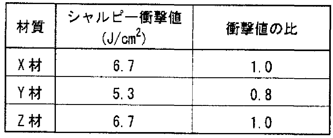


Claims
Priority Applications (4)
| Application Number | Priority Date | Filing Date | Title |
|---|---|---|---|
| EP11162818.6A EP2345822B1 (en) | 2004-08-02 | 2005-07-06 | Rolling bearing for rocker arm and rocker arm |
| US11/659,316 US7614374B2 (en) | 2004-08-02 | 2005-07-06 | Rolling bearing for rocker arm |
| EP09180115.9A EP2159437B1 (en) | 2004-08-02 | 2005-07-06 | Rolling bearing for rocker arm |
| EP05758261.1A EP1788264B1 (en) | 2004-08-02 | 2005-07-06 | Rolling bearing for rocker arm |
Applications Claiming Priority (10)
| Application Number | Priority Date | Filing Date | Title |
|---|---|---|---|
| JP2004225925A JP4737954B2 (ja) | 2004-08-02 | 2004-08-02 | ロッカーアーム用転がり軸受 |
| JP2004-225925 | 2004-08-02 | ||
| JP2004228037A JP2006046173A (ja) | 2004-08-04 | 2004-08-04 | ロッカーアーム用軸受 |
| JP2004-228037 | 2004-08-04 | ||
| JP2004-246463 | 2004-08-26 | ||
| JP2004246463A JP4368765B2 (ja) | 2004-08-26 | 2004-08-26 | ロッカーアーム用転がり軸受 |
| JP2004248859A JP4208797B2 (ja) | 2004-08-27 | 2004-08-27 | ロッカーアームに使用する転がり軸受 |
| JP2004-248859 | 2004-08-27 | ||
| JP2004-275154 | 2004-09-22 | ||
| JP2004275154A JP4737960B2 (ja) | 2004-09-22 | 2004-09-22 | ロッカーアーム用転がり軸受 |
Publications (1)
| Publication Number | Publication Date |
|---|---|
| WO2006013696A1 true WO2006013696A1 (ja) | 2006-02-09 |
Family
ID=35786991
Family Applications (1)
| Application Number | Title | Priority Date | Filing Date |
|---|---|---|---|
| PCT/JP2005/012455 Ceased WO2006013696A1 (ja) | 2004-08-02 | 2005-07-06 | ロッカーアーム用転がり軸受 |
Country Status (3)
| Country | Link |
|---|---|
| US (1) | US7614374B2 (ja) |
| EP (3) | EP2345822B1 (ja) |
| WO (1) | WO2006013696A1 (ja) |
Cited By (4)
| Publication number | Priority date | Publication date | Assignee | Title |
|---|---|---|---|---|
| JP2009293398A (ja) * | 2008-06-02 | 2009-12-17 | Ntn Corp | ポンプ用タペット |
| WO2010097528A1 (fr) | 2009-02-26 | 2010-09-02 | Saipem S.A. | Installation de liaison fond-surface de type tour hybride multi-riser comprenant des modules de flottabilite coulissants |
| US20100319642A1 (en) * | 2008-02-19 | 2010-12-23 | Ntn Corporation | Roller follower, valve train, induction hardening apparatus, method of heat treatment of shaft member, method of manufacturing shaft, and shaft |
| EP2484926A1 (en) * | 2006-10-26 | 2012-08-08 | NTN Corporation | Thermal treatment of the outer ring of a rolling bearing |
Families Citing this family (24)
| Publication number | Priority date | Publication date | Assignee | Title |
|---|---|---|---|---|
| US8109247B2 (en) * | 2008-05-19 | 2012-02-07 | GM Global Technology Operations LLC | Wear resistant camshaft and follower material |
| US9228454B2 (en) | 2010-03-19 | 2016-01-05 | Eaton Coporation | Systems, methods and devices for rocker arm position sensing |
| US20190309663A9 (en) | 2008-07-22 | 2019-10-10 | Eaton Corporation | Development of a switching roller finger follower for cylinder deactivation in internal combustion engines |
| US9267396B2 (en) * | 2010-03-19 | 2016-02-23 | Eaton Corporation | Rocker arm assembly and components therefor |
| US10415439B2 (en) | 2008-07-22 | 2019-09-17 | Eaton Intelligent Power Limited | Development of a switching roller finger follower for cylinder deactivation in internal combustion engines |
| US11181013B2 (en) | 2009-07-22 | 2021-11-23 | Eaton Intelligent Power Limited | Cylinder head arrangement for variable valve actuation rocker arm assemblies |
| US9194261B2 (en) | 2011-03-18 | 2015-11-24 | Eaton Corporation | Custom VVA rocker arms for left hand and right hand orientations |
| JP2011208631A (ja) * | 2010-03-12 | 2011-10-20 | Nsk Ltd | タペットローラ軸受 |
| US9885258B2 (en) | 2010-03-19 | 2018-02-06 | Eaton Corporation | Latch interface for a valve actuating device |
| US9874122B2 (en) | 2010-03-19 | 2018-01-23 | Eaton Corporation | Rocker assembly having improved durability |
| DE102011003023A1 (de) * | 2011-01-24 | 2012-07-26 | Schaeffler Technologies Gmbh & Co. Kg | Kipp- oder Schwinghebel in einem Ventiltrieb einer Brennkraftmaschine |
| DE102012205242A1 (de) * | 2012-03-30 | 2013-10-02 | Schaeffler Technologies AG & Co. KG | Wälzlagerbauteil |
| US8991351B2 (en) | 2013-03-15 | 2015-03-31 | Roller Bearing Company Of America, Inc. | Needle roller cam follower for higher mileage applications of light, medium and heavy duty vehicles |
| WO2014196428A1 (ja) | 2013-06-06 | 2014-12-11 | Ntn株式会社 | 軸受部品および転がり軸受 |
| EP3006577B1 (en) | 2013-06-06 | 2019-07-17 | NTN Corporation | Bearing component and rolling bearing |
| US10156259B2 (en) | 2013-06-06 | 2018-12-18 | Ntn Corporation | Bearing component and rolling bearing |
| EP3006754B1 (en) * | 2013-06-06 | 2021-09-08 | NTN Corporation | Bearing component and rolling bearing |
| DE102013213380A1 (de) * | 2013-07-09 | 2015-01-15 | BSH Bosch und Siemens Hausgeräte GmbH | Linearverdichter für ein Haushaltsgerät und Haushaltskältegerät |
| US20150053160A1 (en) * | 2013-08-20 | 2015-02-26 | Schaeffler Technologies Gmbh & Co. Kg | Slider pad for roller finger follower |
| DE102015207106A1 (de) * | 2015-04-20 | 2016-10-20 | Schaeffler Technologies AG & Co. KG | Verfahren zum Herstellen von Wälzkörpern für Wälzlager |
| JP6799352B2 (ja) * | 2015-06-11 | 2020-12-16 | イートン コーポレーションEaton Corporation | ロッカーアーム及びロッカーアームの製造法、並びに、バルブ開閉力伝達具及びバルブ開閉力伝達具の製造方法 |
| JP2017008400A (ja) * | 2015-06-25 | 2017-01-12 | Ntn株式会社 | 軸受部品の製造方法 |
| US9746034B2 (en) * | 2015-10-28 | 2017-08-29 | Deere & Company | Distributed load bearing with an inner flex ring |
| JP7681942B2 (ja) | 2019-10-01 | 2025-05-23 | Ntn株式会社 | 軸受部品 |
Citations (19)
| Publication number | Priority date | Publication date | Assignee | Title |
|---|---|---|---|---|
| JPH02168022A (ja) | 1988-12-22 | 1990-06-28 | Toyota Motor Corp | 軸受部品 |
| JPH03119508A (ja) | 1989-09-30 | 1991-05-21 | Hitachi Ltd | 薄膜磁気ヘッド,薄膜磁気ヘッド用基板および該基板の製法 |
| JPH03199716A (ja) | 1989-12-27 | 1991-08-30 | Toyota Motor Corp | 軸受部品 |
| JPH07310509A (ja) * | 1994-03-23 | 1995-11-28 | Koyo Seiko Co Ltd | カム従動ローラ |
| JPH1030150A (ja) * | 1996-07-19 | 1998-02-03 | Nippon Seiko Kk | 転がり軸受 |
| JPH1047334A (ja) | 1996-08-02 | 1998-02-17 | Nippon Seiko Kk | 転がり摺動部品 |
| JPH10103339A (ja) | 1996-09-30 | 1998-04-21 | Koyo Seiko Co Ltd | 軸受装置 |
| JPH10110720A (ja) | 1996-10-08 | 1998-04-28 | Mitsubishi Motors Corp | 軸受け構造 |
| JP2000038907A (ja) | 1998-07-21 | 2000-02-08 | Nippon Seiko Kk | エンジンの動弁機構用カムフォロア装置 |
| JP2000038906A (ja) | 1998-07-21 | 2000-02-08 | Nippon Seiko Kk | エンジンの動弁機構用カムフォロア装置 |
| JP2000054811A (ja) * | 1998-08-10 | 2000-02-22 | Nippon Seiko Kk | 板金製ロッカーアームを備えたカムフォロアとその組立方法 |
| JP2000205284A (ja) * | 1999-01-13 | 2000-07-25 | Koyo Seiko Co Ltd | 転がり摺動部品 |
| JP3125434B2 (ja) | 1992-04-07 | 2001-01-15 | 日本精工株式会社 | 転がり摺動部品 |
| JP2001065576A (ja) | 1999-08-27 | 2001-03-16 | Koyo Seiko Co Ltd | 軸受部品素材 |
| JP2001280348A (ja) * | 2000-03-28 | 2001-10-10 | Nsk Ltd | 転がり軸受 |
| JP2002105536A (ja) * | 2000-09-26 | 2002-04-10 | Sanyo Special Steel Co Ltd | 仕上げ研削・研磨性に優れる軸受用素材の製造方法及びその方法により製造の仕上げ研削・研磨性に優れた軸受用素材 |
| JP2002327605A (ja) * | 2001-04-27 | 2002-11-15 | Nsk Ltd | 板金製ロッカーアーム |
| JP2004060797A (ja) * | 2002-07-30 | 2004-02-26 | Koyo Seiko Co Ltd | ローラ部材およびその製造方法 |
| JP2004060807A (ja) * | 2002-07-30 | 2004-02-26 | Ntn Corp | 転がり軸受 |
Family Cites Families (26)
| Publication number | Priority date | Publication date | Assignee | Title |
|---|---|---|---|---|
| JPH0615811B2 (ja) | 1985-07-03 | 1994-03-02 | 本田技研工業株式会社 | ロ−ラ付カムフォロア |
| US4727832A (en) | 1986-06-13 | 1988-03-01 | Mitsubishi Jidosha Kogyo Kabushiki Kaisha | Roller rocker arm |
| JPS63185917A (ja) | 1987-01-26 | 1988-08-01 | Tsumoru Murakami | 発毛促進容液 |
| JPS63185917U (ja) | 1987-05-25 | 1988-11-29 | ||
| JP2743488B2 (ja) | 1989-06-29 | 1998-04-22 | 日本精工株式会社 | エンジンの動弁機構用カムフォロア装置 |
| JPH0363703A (ja) | 1989-07-31 | 1991-03-19 | Omron Corp | 機器出力量の自動調節ファジイ制御装置 |
| JPH0363703U (ja) | 1989-10-25 | 1991-06-21 | ||
| JPH03119508U (ja) | 1990-03-22 | 1991-12-10 | ||
| JPH0826446B2 (ja) * | 1990-05-17 | 1996-03-13 | 日本精工株式会社 | 転がり軸受 |
| JPH0680287B2 (ja) | 1991-02-15 | 1994-10-12 | 本田技研工業株式会社 | ローラ付カムフォロア |
| JPH05179350A (ja) | 1991-12-27 | 1993-07-20 | Ntn Corp | ローラ付カムフォロア用のローラ軸の製造方法 |
| JP3701036B2 (ja) | 1993-12-27 | 2005-09-28 | 株式会社神戸製鋼所 | 高強度歯車 |
| DE19612969B4 (de) * | 1996-04-01 | 2004-04-08 | Ina-Schaeffler Kg | Verfahren zur Herstellung eines Kipp- oder Schlepphebels eines Ventiltriebs einer Brennkraftmaschine |
| JPH11101247A (ja) | 1997-09-29 | 1999-04-13 | Ntn Corp | 転がり軸受部品 |
| US6199527B1 (en) * | 1998-03-12 | 2001-03-13 | Nsk Ltd. | Sheet metal rocker arm, manufacturing method thereof, cam follower with said rocker arm, and assembling method thereof |
| JP2000129347A (ja) | 1998-10-19 | 2000-05-09 | Kobe Steel Ltd | 高強度部品の製造方法 |
| JP3063703U (ja) | 1999-05-10 | 1999-11-26 | 正伸 森崎 | 履口のサイズが変わる靴 |
| JP3869192B2 (ja) | 2000-07-17 | 2007-01-17 | 株式会社ジェイテクト | 転がり摺動部品 |
| JP2002194438A (ja) | 2000-12-22 | 2002-07-10 | Nsk Ltd | 転がり軸受 |
| JP3905429B2 (ja) | 2001-11-29 | 2007-04-18 | Ntn株式会社 | 軸受部品の熱処理方法および軸受部品 |
| DE10315416A1 (de) * | 2002-06-27 | 2004-01-22 | Ina-Schaeffler Kg | Lagefixierung eines Bolzens |
| JP3990254B2 (ja) | 2002-10-17 | 2007-10-10 | Ntn株式会社 | 総ころタイプの転がり軸受 |
| EP1411142B1 (en) | 2002-10-17 | 2006-03-08 | Ntn Corporation | Full-type rolling bearing and roller cam follower for engine |
| JP4486411B2 (ja) * | 2003-06-05 | 2010-06-23 | Ntn株式会社 | ローラ付きカムフォロア |
| JP4319001B2 (ja) * | 2003-10-10 | 2009-08-26 | Ntn株式会社 | 転がり軸受 |
| JP3119508U (ja) | 2005-12-07 | 2006-03-02 | 東洋商事株式会社 | 骨盤矯正エプロン |
-
2005
- 2005-07-06 EP EP11162818.6A patent/EP2345822B1/en not_active Expired - Lifetime
- 2005-07-06 EP EP05758261.1A patent/EP1788264B1/en not_active Expired - Lifetime
- 2005-07-06 EP EP09180115.9A patent/EP2159437B1/en not_active Expired - Lifetime
- 2005-07-06 WO PCT/JP2005/012455 patent/WO2006013696A1/ja not_active Ceased
- 2005-07-06 US US11/659,316 patent/US7614374B2/en not_active Expired - Lifetime
Patent Citations (19)
| Publication number | Priority date | Publication date | Assignee | Title |
|---|---|---|---|---|
| JPH02168022A (ja) | 1988-12-22 | 1990-06-28 | Toyota Motor Corp | 軸受部品 |
| JPH03119508A (ja) | 1989-09-30 | 1991-05-21 | Hitachi Ltd | 薄膜磁気ヘッド,薄膜磁気ヘッド用基板および該基板の製法 |
| JPH03199716A (ja) | 1989-12-27 | 1991-08-30 | Toyota Motor Corp | 軸受部品 |
| JP3125434B2 (ja) | 1992-04-07 | 2001-01-15 | 日本精工株式会社 | 転がり摺動部品 |
| JPH07310509A (ja) * | 1994-03-23 | 1995-11-28 | Koyo Seiko Co Ltd | カム従動ローラ |
| JPH1030150A (ja) * | 1996-07-19 | 1998-02-03 | Nippon Seiko Kk | 転がり軸受 |
| JPH1047334A (ja) | 1996-08-02 | 1998-02-17 | Nippon Seiko Kk | 転がり摺動部品 |
| JPH10103339A (ja) | 1996-09-30 | 1998-04-21 | Koyo Seiko Co Ltd | 軸受装置 |
| JPH10110720A (ja) | 1996-10-08 | 1998-04-28 | Mitsubishi Motors Corp | 軸受け構造 |
| JP2000038906A (ja) | 1998-07-21 | 2000-02-08 | Nippon Seiko Kk | エンジンの動弁機構用カムフォロア装置 |
| JP2000038907A (ja) | 1998-07-21 | 2000-02-08 | Nippon Seiko Kk | エンジンの動弁機構用カムフォロア装置 |
| JP2000054811A (ja) * | 1998-08-10 | 2000-02-22 | Nippon Seiko Kk | 板金製ロッカーアームを備えたカムフォロアとその組立方法 |
| JP2000205284A (ja) * | 1999-01-13 | 2000-07-25 | Koyo Seiko Co Ltd | 転がり摺動部品 |
| JP2001065576A (ja) | 1999-08-27 | 2001-03-16 | Koyo Seiko Co Ltd | 軸受部品素材 |
| JP2001280348A (ja) * | 2000-03-28 | 2001-10-10 | Nsk Ltd | 転がり軸受 |
| JP2002105536A (ja) * | 2000-09-26 | 2002-04-10 | Sanyo Special Steel Co Ltd | 仕上げ研削・研磨性に優れる軸受用素材の製造方法及びその方法により製造の仕上げ研削・研磨性に優れた軸受用素材 |
| JP2002327605A (ja) * | 2001-04-27 | 2002-11-15 | Nsk Ltd | 板金製ロッカーアーム |
| JP2004060797A (ja) * | 2002-07-30 | 2004-02-26 | Koyo Seiko Co Ltd | ローラ部材およびその製造方法 |
| JP2004060807A (ja) * | 2002-07-30 | 2004-02-26 | Ntn Corp | 転がり軸受 |
Non-Patent Citations (1)
| Title |
|---|
| See also references of EP1788264A4 |
Cited By (6)
| Publication number | Priority date | Publication date | Assignee | Title |
|---|---|---|---|---|
| EP2484926A1 (en) * | 2006-10-26 | 2012-08-08 | NTN Corporation | Thermal treatment of the outer ring of a rolling bearing |
| US8313246B2 (en) | 2006-10-26 | 2012-11-20 | Ntn Corporation | Rocker bearing with outer ring and air disk brake system |
| US20100319642A1 (en) * | 2008-02-19 | 2010-12-23 | Ntn Corporation | Roller follower, valve train, induction hardening apparatus, method of heat treatment of shaft member, method of manufacturing shaft, and shaft |
| US8844489B2 (en) * | 2008-02-19 | 2014-09-30 | Ntn Corporation | Roller follower, valve train, induction hardening apparatus, method of heat treatment of shaft member, method of manufacturing shaft, and shaft |
| JP2009293398A (ja) * | 2008-06-02 | 2009-12-17 | Ntn Corp | ポンプ用タペット |
| WO2010097528A1 (fr) | 2009-02-26 | 2010-09-02 | Saipem S.A. | Installation de liaison fond-surface de type tour hybride multi-riser comprenant des modules de flottabilite coulissants |
Also Published As
| Publication number | Publication date |
|---|---|
| EP1788264B1 (en) | 2018-05-16 |
| US20080163839A1 (en) | 2008-07-10 |
| EP2345822B1 (en) | 2019-01-09 |
| EP2159437A2 (en) | 2010-03-03 |
| EP2159437A3 (en) | 2010-10-13 |
| EP1788264A4 (en) | 2009-05-06 |
| EP2345822A3 (en) | 2011-11-23 |
| EP2345822A2 (en) | 2011-07-20 |
| US7614374B2 (en) | 2009-11-10 |
| EP2159437B1 (en) | 2018-10-17 |
| EP1788264A1 (en) | 2007-05-23 |
Similar Documents
| Publication | Publication Date | Title |
|---|---|---|
| CN100504092C (zh) | 滚动轴承、凸轮从动件以及凸轮 | |
| US7614374B2 (en) | Rolling bearing for rocker arm | |
| US7490583B2 (en) | Full-type rolling bearing and roller cam follower for engine | |
| JP4566036B2 (ja) | 転がり軸受 | |
| CN100398856C (zh) | 装满滚子的滚动轴承和用于发动机的滚子凸轮随动件 | |
| CN100516572C (zh) | 摇臂用滚动轴承 | |
| JP2024034952A (ja) | 窒化高周波焼入れ用鋼材及び鋼部品 | |
| JP5318528B2 (ja) | エンジンのローラ付きカムフォロアの製造方法 | |
| JP4897060B2 (ja) | ローラ軸の製造方法 | |
| JP4208797B2 (ja) | ロッカーアームに使用する転がり軸受 | |
| JP2003277882A (ja) | 鉄合金部品およびその製造方法 | |
| JP2004278528A (ja) | エンジンのローラ付きカムフォロアおよび鋼部材 | |
| JP4737960B2 (ja) | ロッカーアーム用転がり軸受 | |
| JP4368765B2 (ja) | ロッカーアーム用転がり軸受 | |
| JP5388264B2 (ja) | 転動軸の製造方法 | |
| JP2006063915A (ja) | ロッカーアーム構造体 | |
| JP4886007B2 (ja) | ロッカーアーム用転がり軸受 | |
| JP2024034953A (ja) | 鋼材及び鋼部品 | |
| JP2006046173A (ja) | ロッカーアーム用軸受 | |
| JP2004060807A (ja) | 転がり軸受 | |
| JP2006063916A (ja) | ロッカーアーム構造体 | |
| JP2020033636A (ja) | 部品およびその製造方法 |
Legal Events
| Date | Code | Title | Description |
|---|---|---|---|
| AK | Designated states |
Kind code of ref document: A1 Designated state(s): AE AG AL AM AT AU AZ BA BB BG BR BW BY BZ CA CH CN CO CR CU CZ DE DK DM DZ EC EE EG ES FI GB GD GE GH GM HR HU ID IL IN IS KE KG KM KP KR KZ LC LK LR LS LT LU LV MA MD MG MK MN MW MX MZ NA NG NI NO NZ OM PG PH PL PT RO RU SC SD SE SG SK SL SM SY TJ TM TN TR TT TZ UA UG US UZ VC VN YU ZA ZM ZW |
|
| AL | Designated countries for regional patents |
Kind code of ref document: A1 Designated state(s): GM KE LS MW MZ NA SD SL SZ TZ UG ZM ZW AM AZ BY KG KZ MD RU TJ TM AT BE BG CH CY CZ DE DK EE ES FI FR GB GR HU IE IS IT LT LU LV MC NL PL PT RO SE SI SK TR BF BJ CF CG CI CM GA GN GQ GW ML MR NE SN TD TG |
|
| 121 | Ep: the epo has been informed by wipo that ep was designated in this application | ||
| WWE | Wipo information: entry into national phase |
Ref document number: 200580025730.6 Country of ref document: CN |
|
| WWE | Wipo information: entry into national phase |
Ref document number: 11659316 Country of ref document: US |
|
| NENP | Non-entry into the national phase |
Ref country code: DE |
|
| WWE | Wipo information: entry into national phase |
Ref document number: 2005758261 Country of ref document: EP |
|
| WWP | Wipo information: published in national office |
Ref document number: 2005758261 Country of ref document: EP |