WO2006098609A1 - Procede et dispositif d'assouplissement du cuir par cisaillement - Google Patents
Procede et dispositif d'assouplissement du cuir par cisaillement Download PDFInfo
- Publication number
- WO2006098609A1 WO2006098609A1 PCT/LT2005/000001 LT2005000001W WO2006098609A1 WO 2006098609 A1 WO2006098609 A1 WO 2006098609A1 LT 2005000001 W LT2005000001 W LT 2005000001W WO 2006098609 A1 WO2006098609 A1 WO 2006098609A1
- Authority
- WO
- WIPO (PCT)
- Prior art keywords
- shear
- skin
- softening
- matrices
- plate
- Prior art date
- Legal status (The legal status is an assumption and is not a legal conclusion. Google has not performed a legal analysis and makes no representation as to the accuracy of the status listed.)
- Ceased
Links
Classifications
-
- C—CHEMISTRY; METALLURGY
- C14—SKINS; HIDES; PELTS; LEATHER
- C14B—MECHANICAL TREATMENT OR PROCESSING OF SKINS, HIDES OR LEATHER IN GENERAL; PELT-SHEARING MACHINES; INTESTINE-SPLITTING MACHINES
- C14B1/00—Manufacture of leather; Machines or devices therefor
- C14B1/40—Softening or making skins or leather supple, e.g. by staking, boarding, or crippling machines, by dry mills
Definitions
- the invention relates to the leather industry and is intended to soften the skin.
- a machine of the type “Mollyca” is known for the softening of leathers and the way in which leather is softened by its repeated stretching (Finishing leather. Ed. By I. P. Strakhov. Moscow, 1983, pp. 329-330, Fig. 91).
- the working parts of the machine are horizontal metal plates, on which protrusions (pegs) are fixed.
- the upper plates are fixed, and the lower plates make a reciprocal movement.
- Each elementary area of skin is bent along a sinusoid and stretched. This method reduces the strength of bonds between collagen bundles.
- This method is intended for mass production, and for processing small parts of the skin it is irrational, in addition, the skin is softened unevenly.
- the closest known technical solution is skin abating with a shear, in which shear forces are applied to reduce the bonding forces between the structural elements of the skin (patent LT 5092; K. Ka ⁇ apaviusius, V. Trisus. Lännener Sotepipig b Shearipg. MATERJALS SCIENCE. ISSN 1392-1320. KAS. ISSN 1392-1320. KA. Tespologiya, 2004. VoI. 10, No. 1. 40- 44 p.).
- the skin to be treated is placed between the grips of the device, one of which is fixed and the other is mobile.
- the skin is treated with strips, the width of which depends on the width of the grips that compress the edges of the skin, and the length on the distance between them.
- the treated leather strip between the grips is in an uncompressed state. To process the entire area of the skin, it must be moved several times through the grippers from one edge to the other. The main disadvantage of this ?
- a well-known technical solution is that the leather parts are softened with individual strips in an uncompressed state, which contributes to the formation of wrinkles, and repeated movement of the skin through the grips increases the process time, and in the marginal areas of movement, the formation of unevenly treated skin areas is possible.
- the patented device and the method of softening skins with a shift with two multi-plate matrices allows the whole part of the skin to be softened in a compressed state over its entire area at once.
- the device for shifting consists of two mirrored blocks of multi-plate matrices, one of which is mounted on the upper part of the main hydraulic motor housing, and the other at the end of the rod of the same hydraulic motor.
- FIG. 1 - a general view of the device
- FIG. 2 lower multiplate matrix (top view)
- FIG. 3 lower multiplate matrix (cross section)
- FIG. 4 - a fragment of the front view of the device
- FIG. 5 skin compression and shear pattern
- FIG. 6 nomogram for the selection of the angle and the number of periods of shift.
- a device for softening leathers by a shift in a compressed state at once over its entire area contains a base 1 with a vertically positioned main linear hydraulic motor of two-sided actions and device for shifting, consisting of two mirror blocks of multi-plate matrices.
- the lower unit 2 is mounted on the upper part of the main hydraulic motor housing, and above it at the end of the same hydraulic motor stem is mounted the upper unit of multi-plate matrices 3.
- Both blocks of multi-plate matrices consist of U-shaped frames 4, in which between the ends of the sidewalls with open sides, parallel to their bases, are mounted the guides 5.
- Each block of multi-plate matrices also contains, to the sliders of the guides with its housings, the connection of separate two-way linear hydraulic motors 6, the rods of which are not Visionally attached to the frames 4, and multi-plate matrices 7, which are inserted into two supporting protrusions, with one ends pivotally attached to the frames and their rectangular grooves facing each other, levers 8.
- the other ends of the levers 8 (Fig. 3) are connected by rods 9 so that so that its wheels 10 lean on the holders 11, and the levers cover the support ears of the holders.
- the holders 11 are attached in one side to the sliders of the guides 5 so as to ensure the movement of the levers 8 along the plane perpendicular to the axes of their rotation.
- the guide supports 12 are mounted so that their guide bars are parallel to the longitudinal axes of movement of the sliders of the guides 5 and moderately press the multi-plate matrices 7 to the guide bars of the holders 11, ensuring smooth sliding of the plates of the matrices between themselves.
- the device contains a safety device 13 on the upper block of matrices 3 and a safety device 14 on the lower block of matrices 2, which are mounted on sliders of the guides 5 interlocked with the shells of hydraulic motors 6 (Fig. 4).
- Leather detail 15 (Fig. 5) is soft in a compressed state between multi-plate matrices 7 over its entire area at once, subjecting to continuous action of shear forces of a certain number of periods and at angles of different size.
- the device contains numerical software that controls the movement of working mechanisms and electronic sensors that measure the current forces.
- the device works as follows.
- the working mechanisms are set in the initial position by the movement of the hydraulic motors: the upper block of the multi-plate matrices 3 is lifted up, the sliders of the guides 5 of both blocks of the matrices 2 and 3 are in the middle position so that the multi-plate matrices 7 create an exact rectangle.
- the main hydraulic motor of the device lowers the upper block of the multi-plate matrices 3 down, catchers 13 and 14 blocks the slide blocks.
- the skin 15 is squeezed by a certain force between the dies 7.
- the hydraulic motors of both blocks 6 synchronously move the interlocked slide blocks, which through the holders 11, the thrust 9 and the levers 8 move both the dies 7 by a given angle of shift a.
- both matrices 7 in the opposite direction by the same angle of shift is performed by reversing the stroke of the hydraulic motors.
- the sliders are set to their original position, and the upper block of the multi-plate matrices 3 rises.
- a bent part of the skin is taken using a patented method (patent LT-5199) to determine the initial mean value of flexibility, which characterizes the softness of the skin, and it is established that initial average of the compliance of the workpiece smoothly
- M is the required increase in compliance
- M e is the reference value of compliance
- the maximum shear angle and the number of periods of action of shear forces are selected according to the calculated increase in skin compliance up to 92%.
- the selected maximum shear angle is 28 degrees
- the number of shear periods is 4.
- the values of shear angles for each period are determined: 1 - 12 degrees, as the minimum effective; 2 - 20 degrees, as the average between the maximum and minimum; 3 and 4 - 28 degrees each, (leveling).
- the working mechanisms of the device set to its original position.
- the part to be blasted is placed on the lower multi-plate matrix, the upper multi-plate matrix is pressed, the software control is switched on, the selected abating modes are inserted and the device is started.
- the compliance of the treated skin part is measured.
- the resulting value is compared with the reference value.
- the compliance of the treated skin is 5.46%, i.e., 0.16% higher than the reference.
- the desired bating effect is achieved.
Landscapes
- Engineering & Computer Science (AREA)
- Manufacturing & Machinery (AREA)
- Mechanical Engineering (AREA)
- Chemical & Material Sciences (AREA)
- Organic Chemistry (AREA)
- Shaping Metal By Deep-Drawing, Or The Like (AREA)
- Treatment And Processing Of Natural Fur Or Leather (AREA)
Description
Устройство и способ мягчения кож сдвигом
Изобретение относится к кожеобрабатывающей промышленности и предназначено для мягчения кож.
Известна машина типа «Moллиca» для мягчения кож и способ, которым кожу мягчат многократным её растяжением (Отделка кож. Ред. И. П. Страхов. Москва, 1983, с. 329-330, рис. 91). Рабочими органами машины служат горизонтально расположенные металлические плиты, на которых укреплены выступы (колки). Верхние плиты неподвижны, а нижние плиты совершают возвратно - поступательное движение. Каждый элементарный участок кожи изгибается по синусоиде и растягивается. Таким методом снижают силы связей между пучками коллагена. Этот способ предназначен для массового производства, а для обработки малых деталей кожи он нерационален, кроме того, кожа смягчается неравномерно.
Ближайшее известное техническое решение - мягчение кожи сдвигом, в котором для снижения сил связи между стуктурными элементами кожи применяют силы сдвига (патент LT 5092; К. Каzапаviсius, V. Тriсуs. Lеаthеr Sоftепiпg bу Shеаriпg. MATERJALS SCIENCE. ISSN 1392-1320. Кашiаs: Тесhпоlоgijа, 2004. VoI. 10, No. 1. 40- 44 р.). Предназначенную для обработки кожу помещают между захватами устройства, один из которых фиксирован а другой подвижный. Используя силы сдвига кожу обрабатывают полосками, ширина которых зависит от ширины захватов, сжимающих края кожи, а длина - от расстояния между ними. Обрабатываемая полоска кожи между захватами находится в несжатом состоянии. Чтобы обработать всю площадь кожи, ее необходимо несколько раз передвигать через захваты с одного края до другого. Основным недостатком этого
? известного технического решения является то, что кожаные детали мягчат отдельными полосками в несжатом состоянии, что способствует образованию морщин, а многократное передвижение кожи через захваты увеличивает продолжительность процесса, причем в краевых зонах передвижения возможно образование неравномерно обработанных участков кожи.
Патентуемое устройство и способ мягчения кож сдвигом с двумя многопластинными матрицами позволяет провести мягчение всей детали кожи в сжатом состоянии сразу по всей её площади.
Приспособление для сдвига состоит из двух зеркально расположенных блоков многопластинновых матриц, один из которых смонтирован на верхней части корпуса основного гидродвигателя, а другой на конце штока того же гидродвигателя.
Кожаную деталь, сжатую между многопластинновыми матрицами, подвергают непрерывному действию сил сдвига определенного количества периодов и под углами разной величины.
Изобретение иллюстрируется чертежами:
Фиг. 1 - общий вид устройства,
Фиг. 2 - нижняя многопластинная матрица (вид сверху),
Фиг. 3 - нижняя многопластинная матрица (поперечний разрез),
Фиг. 4 - фрагмент вида спереди устройства,
Фиг. 5 - сжатие кожи и схема сдвига;
Фиг. 6 - номограмма для подбора угла и количества периодов сдвига.
Устройство для мягчения кож сдвигом в сжатом состоянии сразу по всей её площади (фиг. 1) содержит основание 1 с вертикально расположенным основным линейным гидродвигателем двухстороннего
действия и приспособление для сдвига, состоящее из двух зеркально расположенных блоков многопластинновых матриц. Нижний блок 2 установлен на верхней части корпуса основного гидродвигателя, а над ним на конце штока того же гидродвигателя смонтирован верхний блок многопластинновых матриц 3. Оба блока многопластинновых матриц (фиг. 2) состоят из П-образных рам 4, в которых между концами боковин с открытых сторон, параллельно их основаниям, вмонтированы направляющие 5. Каждый блок многопластинновых матриц также содержит к ползунам направляющих своими корпусами присоединение отдельные линейные гидродвигатели двухстороннего действия 6, штоки которых неподвижно прикреплены к рамам 4, и многопластинновые матрицы 7, которые опорными выступами вставлены в два, одними концами шарнирно присоединенными к рамам и своими прямоугольными канавками обращенными друг к другу, рычага 8. Другие концы рычагов 8 (фиг. 3) соединены тягами 9 так, чтобы тяги своими колесиками 10 опирались на держатели 11, а рычаги охватывали опорные ушки держателей. Держатели 11 одним боком прикреплены к ползунам направляющих 5 так, чтобы обеспечивали передвижение рычагов 8 по плосткости, перпендикулярной осям их вращения. Направляющие опоры 12 смонтированы так, чтобы их направляющие плосткости были параллельны продольним осям передвижения ползунов направляющих 5 и умеренно прижимали многопластинновые матрицы 7 к направляющим плосткостям держателей 11, обеспечивая плавное проскальзывание пластин матриц между собой. Для обеспечения синхронного действия обеих блоков многопластинновых матриц устройство содержит ловитель 13 на верхнем блоке матриц 3 и ловитель 14 на нижнем блоке матриц 2, которые смонтированы на ползунах направляющих 5, сблокированных с корпусами гидродвигателей 6 (фиг. 4).
Кожаную деталь 15 (фиг. 5) мягчат в сжатом состоянии между многопластинновыми матрицами 7 сразу по всей ее площади, подвергая непрерывному действию сил сдвига определенного количества периодов и под углами разной величины.
Устройство содержит числовое программное снаряжение, контролирующее передвижение рабочих механизмов и электронные датчики, измеряющие действующие усилия.
Устройство работает следующим образом.
Движением гидродвигателей рабочие механизмы устанавливают в исходное положение: верхний блок многопластинновых матриц 3 поднимают вверх, ползуны направляющих 5 обоих блоков матриц 2 и 3 занимают среднее положение так, чтобы многопластинновые матрицы 7 создали точный прямоугольник. Основной гидродвигатель устройства опускает верхний блок многопластиновых матриц 3 вниз, ловителями 13 и 14 сблокирует ползуны. Кожу 15 определенной силой сжимают между матрицами 7. Гидродвигатели обеих блоков 6 синхронно передвигают сблокированные ползуны, которые через держатели 11, тяги 9 и рычаги 8 перемещают обе матрицы 7 заданным углом сдвига а. Перемещение обеих матриц 7 в противоположную сторону таким же углом сдвига осуществляется реверсом хода гидродвигателей. Повторным реверсом хода гидродвигателей 6 ползуны устанавливают в исходное положение, а верхний блок многопластинновых матриц 3 поднимается вверх.
Суть изобретения поясняется примером.
Берут подвергаемую мягчению деталь кожи, патентованным способом (патент LT-5199) определяют начальное среднее значение податливости, характеризующее мягкость кожи, и устанавливают, что
начальное среднее значение податливости обрабатываемой детали ровно
2,76 %.
Далее вычисляют величину необходимого увеличения податливости до эталонного значения:
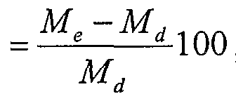
где: M - необходимое увеличение податливости, Me - эталонное значение податливости,
Md - начальное среднее значение податливости детали.

Пользуясь номограммой (фиг. 6), по вычисленному необходимому увеличению податливости кожи до 92 % подбирают максимальную величину угла сдвига и количество периодов действия силами сдвига. Подобранный максимальный угол сдвига - 28 градусов, число периодов сдвига - 4. Далее определяют значения углов сдвига для каждого периода: 1 - 12 град., как минимальный эффективный; 2 - 20 град., как средний между максимальным и минимальным; 3 и 4 - по 28 град, (выравнивающие) .
Рабочие механизмы устройства устанавливают в исходное положение. Подвергаемую мягчению деталь кладут на нижнюю многопластинную матрицу, прижимают верхней многопластинной матрицой, включают программное управление, вводят подобранные режимы мягчения и пускают устройство.
После мягчения в подобранном режиме (максимальный угол сдвига 28 градусов, 4 периода сдвига) измеряют податливость обработанной детали кожи. Полученное значение сравнивают с эталонной величиной. Податливость обработанной кожи составляет 5,46 %, т. е., на 0,16 % превышает эталонную. Желаемый эффект мягчения достигнут.
Claims
1. Устройство для мягчения кож сдвигом, содержащее основание с вертикально расположенным основным линейным гидродвигателем двухстороннего действия и приспособление для сдвига, отличающееся тем, что приспособление для сдвига состоит из двух зеркально расположенных блоков многопластинновых матриц, один из которых смонтирован на верхней части корпуса основного гидродвигателя, а другой на конце штока того же гидродвигателя.
2. Способ мягчения кож сдвигом, отличающийся тем, что кожаную деталь, сжатую между многопластинновыми матрицами по всей ее площади, подвергают непрерывному действию сил сдвига определенного количества периодов и под углами разной величины.
Priority Applications (2)
| Application Number | Priority Date | Filing Date | Title |
|---|---|---|---|
| EP05728261A EP1865077A1 (de) | 2005-03-18 | 2005-03-18 | Vorrichtung und verfahren zum weichmachen von häuten durch scheren |
| PCT/LT2005/000001 WO2006098609A1 (fr) | 2005-03-18 | 2005-03-18 | Procede et dispositif d'assouplissement du cuir par cisaillement |
Applications Claiming Priority (1)
| Application Number | Priority Date | Filing Date | Title |
|---|---|---|---|
| PCT/LT2005/000001 WO2006098609A1 (fr) | 2005-03-18 | 2005-03-18 | Procede et dispositif d'assouplissement du cuir par cisaillement |
Publications (1)
| Publication Number | Publication Date |
|---|---|
| WO2006098609A1 true WO2006098609A1 (fr) | 2006-09-21 |
Family
ID=36991937
Family Applications (1)
| Application Number | Title | Priority Date | Filing Date |
|---|---|---|---|
| PCT/LT2005/000001 Ceased WO2006098609A1 (fr) | 2005-03-18 | 2005-03-18 | Procede et dispositif d'assouplissement du cuir par cisaillement |
Country Status (2)
| Country | Link |
|---|---|
| EP (1) | EP1865077A1 (ru) |
| WO (1) | WO2006098609A1 (ru) |
Cited By (1)
| Publication number | Priority date | Publication date | Assignee | Title |
|---|---|---|---|---|
| CN106676207A (zh) * | 2017-02-28 | 2017-05-17 | 林安益 | 一种皮革软化加工设备 |
Citations (4)
| Publication number | Priority date | Publication date | Assignee | Title |
|---|---|---|---|---|
| US4100771A (en) * | 1975-09-29 | 1978-07-18 | Jiri Dokoupil | Method and apparatus for flexibilizing leather |
| DE3500684A1 (de) * | 1985-01-11 | 1986-07-17 | Wolf 8403 Bad Abbach Ciecierski | Lederbearbeitungsmaschine |
| RU2163931C1 (ru) * | 1999-08-17 | 2001-03-10 | Мухачев Андрей Анатольевич | Машина для тяжки и мягчения кожи |
| LT5092B (lt) * | 2003-05-12 | 2004-01-26 | Šiaulių universitetas | Odų minkštinimo būdas |
-
2005
- 2005-03-18 EP EP05728261A patent/EP1865077A1/de not_active Withdrawn
- 2005-03-18 WO PCT/LT2005/000001 patent/WO2006098609A1/ru not_active Ceased
Patent Citations (4)
| Publication number | Priority date | Publication date | Assignee | Title |
|---|---|---|---|---|
| US4100771A (en) * | 1975-09-29 | 1978-07-18 | Jiri Dokoupil | Method and apparatus for flexibilizing leather |
| DE3500684A1 (de) * | 1985-01-11 | 1986-07-17 | Wolf 8403 Bad Abbach Ciecierski | Lederbearbeitungsmaschine |
| RU2163931C1 (ru) * | 1999-08-17 | 2001-03-10 | Мухачев Андрей Анатольевич | Машина для тяжки и мягчения кожи |
| LT5092B (lt) * | 2003-05-12 | 2004-01-26 | Šiaulių universitetas | Odų minkštinimo būdas |
Cited By (1)
| Publication number | Priority date | Publication date | Assignee | Title |
|---|---|---|---|---|
| CN106676207A (zh) * | 2017-02-28 | 2017-05-17 | 林安益 | 一种皮革软化加工设备 |
Also Published As
| Publication number | Publication date |
|---|---|
| EP1865077A1 (de) | 2007-12-12 |
Similar Documents
| Publication | Publication Date | Title |
|---|---|---|
| US4291732A (en) | Method and apparatus for manufacture of wire truss and sinuous strut therefor | |
| DE102017128677A1 (de) | Verfahren und Vorrichtung zum Formen eines Metallbleches | |
| CN208744319U (zh) | 一种薄钢板等距切割装置 | |
| CN207642075U (zh) | 铁板扭弯装置 | |
| CN110106293A (zh) | 一种皮革的裁剪装置 | |
| US3626746A (en) | Work reducing and shaping apparatus | |
| JP5967821B2 (ja) | 食品生地の丸め成形装置及び丸め成形方法 | |
| US3961738A (en) | Apparatus for making truss members | |
| EP0478242A1 (en) | Method and apparatus for stretching dough | |
| CN107617703B (zh) | 一种建筑钢筋拉直切割设备 | |
| CN208790895U (zh) | 一种针对布料卷边的拨布装置 | |
| CN217578938U (zh) | 一种皮革加工用压平装置 | |
| US3677055A (en) | Apparatus for making shaped bores in a continuous strip | |
| JPH10511044A (ja) | 板金用曲げプレス | |
| US2327757A (en) | Method of raising spines | |
| RU2319605C1 (ru) | Способ обработки ленточного или листового материала и пресс для осуществления указанного способа | |
| CN217517234U (zh) | 一种用于布料裁切加工的工作台 | |
| KR100621597B1 (ko) | 에어콘용 콘덴서 벤딩장치 | |
| JP3236351B2 (ja) | 折曲げ用金型 | |
| RU2078638C1 (ru) | Способ изготовления просечно-вытяжной сетки из полосового материала | |
| KR20110012810A (ko) | 모피 가공 장치 및 방법 | |
| CN220659894U (zh) | 一种不锈钢卷材切割用矫正修平机 | |
| CN222284784U (zh) | 一种服装模板机 | |
| CN112338031B (zh) | 铝格板成型机 | |
| CN119839353B (zh) | 一种焊接互联条处理方法及装置 |
Legal Events
| Date | Code | Title | Description |
|---|---|---|---|
| 121 | Ep: the epo has been informed by wipo that ep was designated in this application | ||
| WWE | Wipo information: entry into national phase |
Ref document number: 2005728261 Country of ref document: EP |
|
| NENP | Non-entry into the national phase |
Ref country code: DE |
|
| NENP | Non-entry into the national phase |
Ref country code: RU |
|
| WWP | Wipo information: published in national office |
Ref document number: 2005728261 Country of ref document: EP |