WO2008010312A1 - Negative electrode active material and negative electrode for lithium ion rechargeable battery - Google Patents
Negative electrode active material and negative electrode for lithium ion rechargeable battery Download PDFInfo
- Publication number
- WO2008010312A1 WO2008010312A1 PCT/JP2007/000739 JP2007000739W WO2008010312A1 WO 2008010312 A1 WO2008010312 A1 WO 2008010312A1 JP 2007000739 W JP2007000739 W JP 2007000739W WO 2008010312 A1 WO2008010312 A1 WO 2008010312A1
- Authority
- WO
- WIPO (PCT)
- Prior art keywords
- graphite particles
- negative electrode
- active material
- electrode active
- particles
- Prior art date
- Legal status (The legal status is an assumption and is not a legal conclusion. Google has not performed a legal analysis and makes no representation as to the accuracy of the status listed.)
- Ceased
Links
Classifications
-
- H—ELECTRICITY
- H01—ELECTRIC ELEMENTS
- H01M—PROCESSES OR MEANS, e.g. BATTERIES, FOR THE DIRECT CONVERSION OF CHEMICAL ENERGY INTO ELECTRICAL ENERGY
- H01M4/00—Electrodes
- H01M4/02—Electrodes composed of, or comprising, active material
- H01M4/36—Selection of substances as active materials, active masses, active liquids
- H01M4/58—Selection of substances as active materials, active masses, active liquids of inorganic compounds other than oxides or hydroxides, e.g. sulfides, selenides, tellurides, halogenides or LiCoFy; of polyanionic structures, e.g. phosphates, silicates or borates
- H01M4/583—Carbonaceous material, e.g. graphite-intercalation compounds or CFx
- H01M4/587—Carbonaceous material, e.g. graphite-intercalation compounds or CFx for inserting or intercalating light metals
-
- H—ELECTRICITY
- H01—ELECTRIC ELEMENTS
- H01M—PROCESSES OR MEANS, e.g. BATTERIES, FOR THE DIRECT CONVERSION OF CHEMICAL ENERGY INTO ELECTRICAL ENERGY
- H01M4/00—Electrodes
- H01M4/02—Electrodes composed of, or comprising, active material
- H01M4/36—Selection of substances as active materials, active masses, active liquids
- H01M4/58—Selection of substances as active materials, active masses, active liquids of inorganic compounds other than oxides or hydroxides, e.g. sulfides, selenides, tellurides, halogenides or LiCoFy; of polyanionic structures, e.g. phosphates, silicates or borates
-
- H—ELECTRICITY
- H01—ELECTRIC ELEMENTS
- H01M—PROCESSES OR MEANS, e.g. BATTERIES, FOR THE DIRECT CONVERSION OF CHEMICAL ENERGY INTO ELECTRICAL ENERGY
- H01M10/00—Secondary cells; Manufacture thereof
- H01M10/05—Accumulators with non-aqueous electrolyte
- H01M10/052—Li-accumulators
- H01M10/0525—Rocking-chair batteries, i.e. batteries with lithium insertion or intercalation in both electrodes; Lithium-ion batteries
-
- H—ELECTRICITY
- H01—ELECTRIC ELEMENTS
- H01M—PROCESSES OR MEANS, e.g. BATTERIES, FOR THE DIRECT CONVERSION OF CHEMICAL ENERGY INTO ELECTRICAL ENERGY
- H01M4/00—Electrodes
- H01M4/02—Electrodes composed of, or comprising, active material
-
- H—ELECTRICITY
- H01—ELECTRIC ELEMENTS
- H01M—PROCESSES OR MEANS, e.g. BATTERIES, FOR THE DIRECT CONVERSION OF CHEMICAL ENERGY INTO ELECTRICAL ENERGY
- H01M4/00—Electrodes
- H01M4/02—Electrodes composed of, or comprising, active material
- H01M4/04—Processes of manufacture in general
-
- H—ELECTRICITY
- H01—ELECTRIC ELEMENTS
- H01M—PROCESSES OR MEANS, e.g. BATTERIES, FOR THE DIRECT CONVERSION OF CHEMICAL ENERGY INTO ELECTRICAL ENERGY
- H01M4/00—Electrodes
- H01M4/02—Electrodes composed of, or comprising, active material
- H01M4/13—Electrodes for accumulators with non-aqueous electrolyte, e.g. for lithium-accumulators; Processes of manufacture thereof
- H01M4/133—Electrodes based on carbonaceous material, e.g. graphite-intercalation compounds or CFx
-
- H—ELECTRICITY
- H01—ELECTRIC ELEMENTS
- H01M—PROCESSES OR MEANS, e.g. BATTERIES, FOR THE DIRECT CONVERSION OF CHEMICAL ENERGY INTO ELECTRICAL ENERGY
- H01M4/00—Electrodes
- H01M4/02—Electrodes composed of, or comprising, active material
- H01M4/36—Selection of substances as active materials, active masses, active liquids
- H01M4/362—Composites
- H01M4/366—Composites as layered products
-
- H—ELECTRICITY
- H01—ELECTRIC ELEMENTS
- H01M—PROCESSES OR MEANS, e.g. BATTERIES, FOR THE DIRECT CONVERSION OF CHEMICAL ENERGY INTO ELECTRICAL ENERGY
- H01M4/00—Electrodes
- H01M4/02—Electrodes composed of, or comprising, active material
- H01M4/36—Selection of substances as active materials, active masses, active liquids
- H01M4/58—Selection of substances as active materials, active masses, active liquids of inorganic compounds other than oxides or hydroxides, e.g. sulfides, selenides, tellurides, halogenides or LiCoFy; of polyanionic structures, e.g. phosphates, silicates or borates
- H01M4/583—Carbonaceous material, e.g. graphite-intercalation compounds or CFx
-
- H—ELECTRICITY
- H01—ELECTRIC ELEMENTS
- H01M—PROCESSES OR MEANS, e.g. BATTERIES, FOR THE DIRECT CONVERSION OF CHEMICAL ENERGY INTO ELECTRICAL ENERGY
- H01M4/00—Electrodes
- H01M4/02—Electrodes composed of, or comprising, active material
- H01M2004/021—Physical characteristics, e.g. porosity, surface area
-
- H—ELECTRICITY
- H01—ELECTRIC ELEMENTS
- H01M—PROCESSES OR MEANS, e.g. BATTERIES, FOR THE DIRECT CONVERSION OF CHEMICAL ENERGY INTO ELECTRICAL ENERGY
- H01M4/00—Electrodes
- H01M4/02—Electrodes composed of, or comprising, active material
- H01M2004/026—Electrodes composed of, or comprising, active material characterised by the polarity
- H01M2004/027—Negative electrodes
-
- Y—GENERAL TAGGING OF NEW TECHNOLOGICAL DEVELOPMENTS; GENERAL TAGGING OF CROSS-SECTIONAL TECHNOLOGIES SPANNING OVER SEVERAL SECTIONS OF THE IPC; TECHNICAL SUBJECTS COVERED BY FORMER USPC CROSS-REFERENCE ART COLLECTIONS [XRACs] AND DIGESTS
- Y02—TECHNOLOGIES OR APPLICATIONS FOR MITIGATION OR ADAPTATION AGAINST CLIMATE CHANGE
- Y02E—REDUCTION OF GREENHOUSE GAS [GHG] EMISSIONS, RELATED TO ENERGY GENERATION, TRANSMISSION OR DISTRIBUTION
- Y02E60/00—Enabling technologies; Technologies with a potential or indirect contribution to GHG emissions mitigation
- Y02E60/10—Energy storage using batteries
-
- Y—GENERAL TAGGING OF NEW TECHNOLOGICAL DEVELOPMENTS; GENERAL TAGGING OF CROSS-SECTIONAL TECHNOLOGIES SPANNING OVER SEVERAL SECTIONS OF THE IPC; TECHNICAL SUBJECTS COVERED BY FORMER USPC CROSS-REFERENCE ART COLLECTIONS [XRACs] AND DIGESTS
- Y02—TECHNOLOGIES OR APPLICATIONS FOR MITIGATION OR ADAPTATION AGAINST CLIMATE CHANGE
- Y02P—CLIMATE CHANGE MITIGATION TECHNOLOGIES IN THE PRODUCTION OR PROCESSING OF GOODS
- Y02P70/00—Climate change mitigation technologies in the production process for final industrial or consumer products
- Y02P70/50—Manufacturing or production processes characterised by the final manufactured product
-
- Y—GENERAL TAGGING OF NEW TECHNOLOGICAL DEVELOPMENTS; GENERAL TAGGING OF CROSS-SECTIONAL TECHNOLOGIES SPANNING OVER SEVERAL SECTIONS OF THE IPC; TECHNICAL SUBJECTS COVERED BY FORMER USPC CROSS-REFERENCE ART COLLECTIONS [XRACs] AND DIGESTS
- Y02—TECHNOLOGIES OR APPLICATIONS FOR MITIGATION OR ADAPTATION AGAINST CLIMATE CHANGE
- Y02T—CLIMATE CHANGE MITIGATION TECHNOLOGIES RELATED TO TRANSPORTATION
- Y02T10/00—Road transport of goods or passengers
- Y02T10/60—Other road transportation technologies with climate change mitigation effect
- Y02T10/70—Energy storage systems for electromobility, e.g. batteries
-
- Y—GENERAL TAGGING OF NEW TECHNOLOGICAL DEVELOPMENTS; GENERAL TAGGING OF CROSS-SECTIONAL TECHNOLOGIES SPANNING OVER SEVERAL SECTIONS OF THE IPC; TECHNICAL SUBJECTS COVERED BY FORMER USPC CROSS-REFERENCE ART COLLECTIONS [XRACs] AND DIGESTS
- Y10—TECHNICAL SUBJECTS COVERED BY FORMER USPC
- Y10T—TECHNICAL SUBJECTS COVERED BY FORMER US CLASSIFICATION
- Y10T29/00—Metal working
- Y10T29/49—Method of mechanical manufacture
- Y10T29/49002—Electrical device making
- Y10T29/49108—Electric battery cell making
- Y10T29/49115—Electric battery cell making including coating or impregnating
Definitions
- the present invention relates to a carbon-based negative electrode active material for a lithium-ion secondary battery used in a notebook computer, a mobile phone, etc., and has a high capacity, a small capacity loss, and a repeated charge / discharge characteristic (cycle characteristic).
- the present invention relates to a negative electrode using the active material.
- Lithium ion secondary batteries are frequently used as portable batteries, video cameras, and other portable devices as high-capacity, high-voltage, small and lightweight secondary batteries.
- high-power type power supplies for power tools that require high power are becoming popular.
- each part and material of lithium ion secondary batteries has been improved, but among them, the negative electrode material has a high density and high capacity is important as it affects the performance of the battery.
- the negative electrode material has a high density and high capacity is important as it affects the performance of the battery.
- it is proposed to spheroidize graphite particles in Japanese Patent No. 9 8 300.
- Patent Document 5 Japanese Patent Laid-Open No. 7-2 4 9 4 11 discloses a carbonizable material as an inert material for the purpose of obtaining a negative electrode material for a lithium ion secondary battery having a large discharge capacity. It is disclosed that carbonization treatment is performed at a temperature of about 500 to 3300 ° C after pretreatment in an atmosphere at a pressure of 10 kgf Z cm 2 or more and a heat treatment temperature of 600 ° C or less. . Specifically, if the carbonizable material is an easily graphitizable material, the carbon is from 1500 to 3300 ° C, and if it is a nongraphitizable material, carbon is from 5500 to 15500 ° C. Turn into It is said.
- Patent Document 6 Japanese Patent Laid-Open No. 11-73963
- a slurry composed of filler graphite, a carbonizable binder, and a solvent for dissolving the binder is formed into a spherical shape by a spray drying method. And dried to obtain a granulated product, and then the caking material is infusible, or the granulated product is 900 to 900 in an inert atmosphere without infusibility.
- a composite material for a negative electrode of a lithium ion secondary battery is described in which the binder is carbonized by heat treatment at 400 ° C. to form a carbon matrix.
- Patent Document 1 Japanese Patent No. 2983003
- Patent Document 2 Japanese Patent No. 3588354
- Patent Document 3 Japanese Patent No. 37 1 6830
- Patent Document 4 Japanese Patent No. 37 1 681 8
- Patent Document 5 Japanese Patent Laid-Open No. 7_24941 1
- Patent Document 6 Japanese Patent Laid-Open No. 11-73963
- Lithium-ion batteries as HEV power supplies are required to have higher input / output characteristics than small lithium-ion batteries used in conventional portable devices, but development has just begun.
- the scaly natural graphite In order to realize a high capacity, it is preferable to use scaly natural graphite in order to realize a high capacity, but the scaly natural graphite has a charge / discharge efficiency of less than 90%.
- the particles When coated on copper foil, the particles are extremely oriented in the plane direction, causing problems in terms of cycle characteristics, and also in terms of low-temperature characteristics.
- the continuous flow path between the particles through which the electrolytic solution passes is blocked, resulting in deterioration of battery characteristics, and it is practically impossible to use scaly natural graphite as it is.
- the method of coating the resin or pitch is, for example, performed by a heating kneader or a mechanical treatment (mechanochemical method).
- a heating kneader When using a heating kneader, it can be manufactured at a relatively low cost, but when using a mechanochemical method, it is inferior to the method using a heating kneader in terms of productivity.
- the coating film formed on the surface of the graphite particles produced by any of the above methods is smooth.
- Graphite particles produced by a conventional coating method are generally spherical and have a smooth surface. Therefore, if the graphite particles are used to form an electrode and charge and discharge are repeated, the negative electrode material is repeatedly expanded and contracted. Reversing reduces the number of contacts between the negative electrode material particles, destroying the conductive network in the electrode, which tends to cause problems with cycle characteristics.
- the present invention provides a graphite particle as a negative electrode material for a lithium ion secondary battery having a high energy density, a small capacity loss during initial charge / discharge, and excellent load characteristics such as rapid charge / discharge, and a negative electrode using the same This is a proposal.
- a base material obtained by spherically shaping flaky natural graphite is impregnated with a mixture of pitch and carbon black, and baked at 900 ° C 1 500 ° C for pulverization and sieving.
- a mixture of pitch- and car-pump racks which are roughly spherical graphite particles (A) with fine protrusions, and a carbonaceous particle (C) that has been baked, pulverized, and sized at 900 ° C 1 500 ° C are also mixed with lithium It is useful as a negative electrode active material for secondary batteries.
- These negative electrode active materials the wavelength 51 4. 5 nm in Ramansu Bae vector spectroscopy using argon laser Raman, 1 600 cm- around 1, and 1 5 80 cm- 1 near to the G-band having a peak
- the composite peak and at least one peak in the vicinity of 1 380 cm- 1 of the D band, the interplanar spacing d obtained by wide-angle X-ray diffraction is 0.335. It is an excellent negative electrode active material for lithium ion secondary batteries that has both high power and high energy density.
- the spherically shaped natural graphite used for the graphite particles (A) and the graphite particles (B) may have an average particle size of about 325 m. Particles with an average particle size of 3 Um or less are difficult to be formed into a spherical shape, and the productivity is reduced, so there is a problem in terms of cost, and in addition, impregnation with pitch and carbon black. In this case, since the particle diameter is small, it is difficult to produce a composite having a uniform particle size distribution, which is not preferable. In addition, when the average particle size is 25 il m or more, the existence ratio of particles exceeding 70 m is high due to the particle size distribution, and the generally considered thin thickness is about 40 m. In the case of electrodes, there will be a problem during coating, so it is preferable to keep the average particle size at 25 m and the maximum particle size at about 75 m at most.
- graphite particles (A) impregnated with a mixture of pitch and carbon black separately on two or more types of base materials with different average particle sizes of spheroidized natural graphite particles as the base material.
- Graphite particles (A1, A2, A3, ⁇ ) that have been baked at 90 ° C to 15500 ° C, crushed and sieved, and powder properties, etc.
- Graphite particles (A) are obtained by impregnating carbon black and pitch into natural graphite shaped into a spherical shape, mixing it, and mixing it, and then coating the surface with carbon black and pitch. Crushed, crushed, and sized through a sieve. Spherical natural graphite, carbon black, and pitch may be mixed after mixing, or carbon black may be added while mixing spherical natural graphite and pitch. Note that chaos means an operation in which a processed material is charged into a kneader and kneaded while heating.
- the graphite particle (A) has a large number of fine protrusions on the particle surface in which carbon black and carbon derived from pitch are combined. For this reason, the surface area is large compared to particles with a smooth surface, and there are many contact points between the particles, and there are many conductive networks in the electrode.
- a negative electrode material having excellent charge / discharge characteristics and power characteristics.
- the amount of carbon black is desirably 2 to 50 parts by weight with respect to 100 parts by weight of natural graphite.
- the amount of carbon black is less than 2% with respect to natural graphite, the amount of microprojections is small and sufficient effects cannot be obtained.
- the amount of carbon black exceeds 50%, the specific surface area is too large, and the capacity loss is not preferable.
- Firing is performed at 90 ° C to 15500 ° C in a non-oxidizing atmosphere. Below 90 ° C, functional groups on the particle surface remain and react with lithium ions, resulting in an increase in capacity loss and an inflection point in the vicinity of 1 V of the discharge curve.
- Graphitization generally refers to heat treatment at 200 ° C. or higher.
- the heat treatment is performed at 900 ° C. to 200 ° C.
- the treatment at a temperature close to 200 ° C. is a treatment temperature in the vicinity of the lowest discharge capacity, it is actually 90 ° C. to 1500 ° C. or less, preferably 9 0 0 ° C to 1 200 ° C or less.
- the carbonaceous particles (C) are carbonaceous porous powders obtained by calcining, pulverizing, and pulverizing a mixture of carbon black and pitch, and performing particle size adjustment using an airflow classifier or sieving. Specifically, carbon black and pitch are put into the first kneader, etc., mixed while heating, and after the pitch is sufficiently wetted with carbon black and combined, it is taken out from the first kneader and made of metal, ceramic Alternatively, transfer to a graphite container and fire in a non-oxidizing atmosphere.
- Firing is carried out at 90 ° C. to 150 ° C. as in the case of graphite particles (A).
- the reason for firing in this temperature range is the same as in the case of graphite particles (A).
- the mixing ratio of carbon black and pitch is determined in consideration of the intended properties of the generated carbonaceous particles (C) and the oil absorption of carbon black.
- the standard is about 25 to 25 parts by weight. 2 If the amount is 5 parts by weight or less, the amount of pitch is too small to be combined with carbon black. If the amount exceeds 2500 parts by weight, the pitch is It becomes excessive with respect to the pitch, too close to the physical properties close to the sintered product of the pitch alone, and deviates from the spirit of the present invention.
- carbon black there are several known types of carbon black, such as furnace black, acetylene black, ketjen black, and lamp black, which have different raw materials and manufacturing methods.
- the size of the structure (DBP oil absorption: expressed by the amount of dibutyl phthalate oil absorption) formed by multiple primary particles of several tens of nm, specific surface area measured by adsorption / desorption of nitrogen gas
- the brands are classified more complicatedly due to differences in size, pore size distribution, and other characteristics.
- the brand of carbon black actually used is not particularly limited, but it is necessary to select the brand and determine the blending amount in consideration of the desired physical properties.
- the amount of carbon black is 2 to 50 parts by weight with respect to 100 parts by weight of natural graphite.
- the amount of carbon black is less than 2% with respect to natural graphite, the amount of microprojections is small and sufficient effects cannot be obtained. If the amount of carbon black exceeds 50%, the surface area is too large, and the capacity loss is undesirably large.
- a general binder pitch or pitch for impregnation can be used. It may be coal-based or petroleum-based, but the softening point is about 70 to 250 ° C, preferably about 80 to 150 ° C, more preferably about 80 to 120 ° C. . If the softening point is too low, handling is inconvenient, and the rate of residual coal is low, which causes high costs. On the other hand, if the softening point is too high, it is unsuitable for processing with a general heating solder, and special equipment must be used, which is not suitable for mass production. Also, the pitch price will be high, which is not favorable from a cost perspective.
- the heat treatment temperature is 90 ° C to 3200 ° C.
- the heat treatment temperature is less than 900 ° C., functional groups on the particle surface remain and react with lithium ions, which causes an increase in capacity loss and generation of an inflection point near the discharge curve of 1 V.
- the calcining temperature in the graphitization treatment for obtaining the graphite particles (B) must be at least 200 ° C. or higher. However, in order to increase the discharge capacity and the charge / discharge efficiency, It is preferable to graphitize at a high temperature.
- the firing temperature for obtaining the graphite particles (B) is 2600 ° C or higher, preferably 2800 ° C or higher, more preferably 3000 ° C or higher. Since the graphite sublimates when the heat treatment temperature exceeds 3400 ° C, the heat treatment at 3200 ° C is the limit.
- the particle size generally used conventionally that is, the average particle size D 50 is 8-25. About m is preferable.
- the average particle diameter D 5 Q about 3 to 15 m, more preferably about 5 to 13 m.
- the maximum particle size must be kept to a size that does not exceed the thickness of the electrode.
- means such as adding an auxiliary conductive agent can be appropriately selected in accordance with the necessity. If the average particle diameter D is 3 m or less, problems such as difficult grinding and high production costs, a large specific surface area, and extremely poor handling properties occur.
- the maximum particle size is suitably 55 m or less. Since electrodes for high power use have an electrode thickness of 40 to 50 m after pressing, if the maximum particle size is 55 m or more, a smooth and uniform coating cannot be obtained.
- the average particle size and Z or maximum particle size of the negative electrode active material can be increased depending on the electrode thickness.
- the diameter D 50 is preferably 25 m and the maximum particle size is preferably 75 m.
- PC propylene carbonate
- Graphite particles (A) have an amorphous surface and a hard particle surface.
- FIG. 1 is an electron micrograph of graphite particles of the present invention.
- Figure 2 Graph showing cycle characteristics.
- FIG. 4 is a graph of constant current charge capacity of the example and the comparative example.
- FIG. 5 is a graph of the constant current charge retention rate of the example and the comparative example.
- FIG. 6 is a graph of discharge capacities of examples and comparative examples.
- FIG. 7 is a graph of discharge capacity retention ratios of examples and comparative examples.
- FIG. 8 Raman spectroscopic spectrum of the graphite particles (A) of the present invention.
- FIG. 10 is a Raman spectroscopic spectrum of an example of the negative electrode active material of the present invention.
- FIG. 11 shows the results of Raman spectral spectrum fitting of an example of the negative electrode active material of the present invention.
- FIG. 1 (A) An electron micrograph of this graphite particle is shown in Fig. 1 (A).
- the graphite particles (A) were further fired at 3000 ° C to obtain graphite particles (B).
- Average particle diameter D 50 1.96 m
- maximum particle diameter Dtop 38.9 m
- specific surface area by BET method SSA 3.4 7 m 2 Z.
- the crystal plane spacing by X-ray diffraction is measured by the Gakushin method.
- 0 0 () 2 3. 357 A.
- the electrode density was 1.46 gZ cm 3 .
- the graphite particles of Comparative Example 1 were further calcined at 3000 ° C.
- the average particle size D 50 13.1 m
- the maximum particle size Dtop 38.9 m
- the crystal plane spacing by X-ray diffraction was measured by the Gakushin method.
- 0 0 () 2 3. 356
- a Specific surface area by BET method SSA 1.37m 2 Zg.
- the graphite particles of Example 1 and Example 2 have high electrode density when pressed, good pressability, and short electrolyte immersion time, Immersion is good.
- Electrolyte immersion time for the electrode density of 1.80 gZcm 3 is 1520 seconds and 1 170 seconds for Examples 1 and 2, respectively. Even so, it has high electrolyte permeability and is excellent as a negative electrode active material.
- the immersion time of the electrolyte is as long as 2990 seconds because the graphite particles are crushed by the press and the flow path of the electrolyte is blocked.
- the graphite particles (B) are easily crushed by the press, but the immersion time is shortened because the flow path is secured by the presence of the protrusions on the surface.
- Example 1 The graphite density of Example 1 and Example 2 was used as the negative electrode active material, and the electrode density was 1.6.
- Table 2 shows the discharge capacity and discharge efficiency when changed to 1.7 and 1.8 (gZcm 3 ). Shown in Charging / discharging was performed by preparing a bipolar coin cell using Li metal as the counter electrode and 1 ML i PF 6 ZEC: M EC (1: 2) as the electrolyte. Constant current charging was performed at a current value of 0.5 mAZcm 2 , and switching to constant voltage charging was performed when the voltage value reached 0.01 V, and charging was continued until the current value dropped to 0.01 mAZ cm 2 . After charging, a constant current discharge was performed at a current value of 0.5 mAZcm 2 and the discharge was terminated when the voltage value reached 1.5 V.
- the graphite particles of the present invention are excellent without decreasing the discharge capacity and efficiency even when the electrode density is increased.
- the graphite particles (A) that are precursors of the graphite particles (B) used in Example 1 were used as they were.
- 002 3.357 A
- specific surface area by BET method SSA 3.65 m 2 Z g.
- Graphite particles A slurry prepared by mixing 5 parts by weight of PVd F (polyvinylidene fluoride) with 100 parts by weight or 2 parts by weight of SBR and CMC on a copper foil. It was coated using 120, dried at 120 ° C, and roll-pressed to form an electrode. The electrode thickness after pressing was 80 m, and the electrode density was 1.6 gZ cm 3 .
- Example 3 is the same as Example 3 except that furnace black (particle diameter 68 nm, BET specific surface area 23 m 2 Z g) was used instead of acetylene black.
- the average particle size D 50 13.5 m
- the maximum particle size Dtop 38.9 m
- the crystal spacing measured by X-ray diffraction was measured by the Gakushin method.
- 0 0 () 2 3.357 A.
- DOD depth of discharge
- Example 3 Using the graphite particles of Example 1, Example 3 and Comparative Example 1, a cycle test was conducted at an electrode density of 1.6 g Zcm 3 . Not to put a constant current charge at a current value of 0. 5 C, switched to a constant voltage charging at the voltage value becomes 0. 01 V, was charged until the current value drops to 0. 01 mAZcm 2. After charging, constant current discharge was performed at a current value of 0.5 C, and the discharge was terminated when the voltage value reached 1.5 V. This charge and discharge was repeated and a cycle test was conducted. Figure 2 shows the results.
- the electrode using Comparative Example 1 having no microprotrusions on the surface has a lower discharge capacity retention rate as the number of cycles increases, whereas the one using the graphite particles of the present invention as a negative electrode active material is The decrease in capacity is small, and excellent cycle characteristics are exhibited.
- Example 1 of the high-density use type the electrode density was set to 1.8 gZcm 3
- Figure 3 shows the cycle characteristics. It has a cycle characteristic equivalent to an electrode density of 1.6 gZcm 3 , no cycle deterioration due to higher electrode density, and excellent characteristics.
- Graphite particles (A) and carbonaceous particles (C) were produced under different conditions as described below, and the performance of these mixtures as a negative electrode material for lithium secondary batteries was tested.
- the mixing ratio in the following is a weight ratio.
- a mixture of pitch and carbon black is separately impregnated and coated on two or more kinds of base materials whose average particle size of the spheroidized natural graphite particles as the base material is changed, and 900 ° C to 1 500 ° C Graphite particles (A 1, A2, A3, ⁇ ⁇ ⁇ ) that have been baked, crushed, and sieved, and graphite particles (A 1, A2, A3, ⁇ ⁇ ⁇ ) depending on the purpose of powder properties, etc. )
- Examples of a negative electrode active material for a lithium ion secondary battery in which carbon atoms and carbonaceous particles (C 1, C 2) are mixed at an arbitrary ratio are shown below.
- a 1 Spherical shaped average particle diameter D 50 of 11 m, maximum particle diameter D top of natural graphite 100 parts by weight and arithmetic average particle diameter 46 nm, DBP oil absorption 106 m IZ 1 00 g, 8 Kenting specific surface area 38 2 £, iodine adsorption amount 4 OmgZg of commercial furnace black 20 parts by weight were mixed, and after adding 5 parts by weight of binder pitch 15 at softening point 110 ° C, heating The kneader was used for 1 hour at 150 ° C. This was calcined at 1 000 ° C in a non-oxidizing atmosphere, crushed, and passed through a sieve having a mesh size of 38 m to obtain roughly spherical graphite particles (A 1).
- a 2 spherically shaped average particle diameter D 50 of 11 m, maximum particle diameter D top of 28 m natural graphite 100 parts by weight, arithmetic average particle diameter 35 nm, DBP oil absorption 1 60 m IZ 1 00 g, 8 Kenting specific surface area 69 2 £, iodine adsorption amount 93 mg Zg of commercial acetylene black 20 parts by weight were mixed, and softening point 1 10 ° C binder pitch 1 8 parts by weight was added After that, the mixture was kneaded at 150 ° C for 1 hour using a heating kneader.
- a 3 spherically shaped average particle diameter D 5Q is 23 m, maximum particle diameter D top is 65 m natural graphite 100 parts by weight, arithmetic average particle diameter 35 nm, DBP oil absorption 160 m 20 parts by weight of commercially available acetylene black having an IZ of 100 g, a specific surface area of 8 kending, 69 2 £, and an iodine adsorption of 93 mgZg were mixed, and further a binder pitch of 10 ° C.
- A4 spherically shaped average particle size D 5Q of 23 m, maximum particle size D top of natural graphite of 100 parts by weight, arithmetic average particle size of 46 nm, DBP oil absorption of 106 m
- IZ 1 00 g 8 Kenting specific surface area 38 2 £
- iodine adsorption amount 4 OmgZg 6 parts by weight of binder pitch 1 10 ° C softening point
- the mixture was kneaded at 150 ° C for 1 hour using a heating kneader. This was calcined at 1 000 ° C. in a non-oxidizing atmosphere, crushed, and passed through a sieve having an opening of 38 m to obtain roughly spherical graphite particles (A4).
- A5 Spherical shaped average particle size D 5Q is 5 m, maximum particle size D top is 17 m natural graphite 100 parts by weight, arithmetic average particle size 46 nm, DBP oil absorption 106 m IZ 1 OO g, 8 Kencho specific surface area 38 2 £, iodine adsorption amount 4 OmgZg of commercial furnace black 20 parts by weight were mixed, and 20 parts by weight of binder pitch with a softening point of 110 ° C was added. Thereafter, the mixture was kneaded at 150 ° C for 1 hour using a heating kneader. This was calcined at 1 000 ° C in a non-oxidizing atmosphere, crushed, and passed through a sieve having an opening of 38 m to obtain roughly spherical graphite particles (A5).
- a 6 Spherical shaped average particle diameter D 5Q is 5 m, maximum particle diameter D top is 17 m natural graphite 100 parts by weight, arithmetic average particle diameter 24 nm, DBP oil absorption 1 15 m IZ 1 OO g, BET specific surface area 1 1 7m 2 Zg, iodine adsorption amount 80 mg Z g commercial furnace black 10 parts by weight are mixed, and softening point 1 10 ° C binder pitch 20 parts by weight is added. After that, the mixture was kneaded at 150 ° C for 1 hour using a heating kneader.
- C 1 Arithmetic mean particle size 24 nm, DBP oil absorption 1 1 5 ml l Z1 00 g, BE T specific surface area 1 1 7 m 2 Zg, iodine adsorption 8 omgZg commercial furnace black 1 00 parts by weight and softening point 1 1
- the mixture was kneaded at 150 ° C. for 1 hour using a heating kneader. This was calcined at 1 000 ° C in a non-oxidizing atmosphere, pulverized, and passed through a sieve having an opening of 38 m to obtain carbonaceous particles (C 1).
- C 2 Commercial furnace black with an arithmetic average particle size of 23 nm, DBP oil absorption of 10 08 ml Z1 00 g, BE T specific surface area of 1 23 m 2 Zg, iodine adsorption of 1 1 5 mg Z g 100 parts by weight
- the mixture was kneaded at 150 ° C. for 1 hour using a heating kneader. This was calcined at 1 000 ° C in a non-oxidizing atmosphere, pulverized, and passed through a sieve having an opening of 38 m to obtain carbonaceous particles (C2).
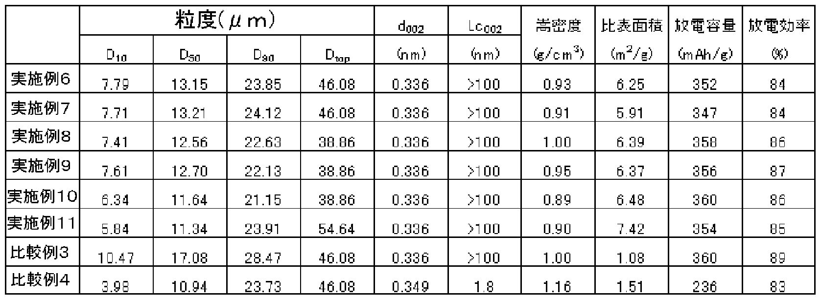
- Softening point with 10% QI component 110 ° C coal pitch (optical isotropic) under nitrogen gas bubbling (2 1 1 Zm in ⁇ kg) Heat treatment at 500 ° C, Polarizing microscope A carbon precursor with an optical anisotropy of 30% was obtained. Volatile content was 0.3%. The softening point was measured by the Mettler method but was not observable and could not be measured. This was pulverized and sized to obtain an average particle diameter D 50 8 m, and then fired at 1300 ° C. in a non-oxidizing atmosphere. Table 5 shows the physical properties of this product.
- Comparative Example 3 is the same as in Examples 6 to 11, and the specific surface area is Although the discharge capacity was as small as 1 Z5 in Examples 6 to 11, the discharge capacity was equivalent to that in Examples 6 to 11. Comparative Example 4 has a large interplanar spacing d 002 compared to Examples 6 to 11, exceeding 0.337 nm, and a considerably low discharge capacity.
- a paste obtained by adding an organic binder and a dispersion medium to the negative electrode active material for a lithium ion secondary battery of Examples 6 to 11 and kneading was applied onto a metal current collector, dried, and pressed. It was confirmed that a negative electrode with a coating thickness of 30 to 100 m and an electrode density of 0.9 to 1.8 gZcm 3 can be rapidly charged and discharged and has excellent high output characteristics.
- paste a paste obtained by adding an organic binder and a dispersion medium to the negative electrode active materials for lithium ion secondary batteries of the examples and comparative examples, and coating them on a metal current collector, followed by drying and pressing.
- Example 6 and Example 1 the decrease in the constant current charge capacity, constant current charge retention rate, discharge capacity, and discharge retention rate when charging and discharging are performed with the charge rate and discharge rate increased is Comparative Example 3. Compared to Comparative Example 4, it is small, indicating that both rapid charge and rapid discharge performance are excellent.
- Diffraction grating S ingle 600 sr Zmm Distribution: Sing I e 21 AZmm
- Measurement was performed by arbitrarily selecting three points from the sample surface.
- the fitting was performed with a three-component Lorentz function and a one-component background component.
- the peak position was fixed at 1600 cm- 1 .
- the background component seems to be derived from amorphous carbon, but since the spectrum shape is unknown, fitting was performed by approximating it with a Gaussian function.
- the baseline was approximated by a straight line at 600 to 2000 cm- 1 .
- I D D intensity of the band (1 360 c m_ near 1)
- I 1360 Intensity of D band (near 1 360 cm- 1 )
- a 1360 D integrated intensity of the band (1 360 c m_ near 1)
- a 1380 Area intensity of Raman band near 1 380 cm- 1 (amorphous component)
- a 1580 Area strength of G band (near 1 580 cm 1 ) (high crystalline component)
- a leakage Area strength of G 'band (around 1 600 cm- 1 ) (low crystalline component)
- the measured depth of the Raman spectrum depends on the absorption coefficient of the sample. For black materials such as carbon, the measurement depth is small. In the case of graphite, the expected measurement depth is about 15 nm due to the absorption coefficient at 514.5 nm excitation. In the case of amorphous carbon, the measurement depth is generally large and is estimated to be several tens of nm.
- X-ray wide-angle diffraction is performed using Rigaku Corporation's X-ray diffractometer RI NT-U I tima III, which uses the silicon silicon as an internal standard for the crystallite size and network size of artificial carbon materials.
- the study was conducted based on the Gakushin method, which stipulates the method of structural analysis.
- Tap density is 60 ⁇ 0.1 g in a 10 Om I graduated cylinder, set in a self-made tap density measuring instrument with a cam inside, and sample after 700 taps with a stroke of 1 Omm. It was calculated from the volume.
- the specific surface area is measured by the pore volume and the pore diameter by adsorption / desorption of nitrogen gas, and the measuring device is an automatic specific surface area Z pore distribution measuring device Tristar 3000 manufactured by Micrometics. used.
- the specific surface area was determined by the BET multipoint method, which calculates the surface area by evaluating the amount of adsorbed gas obtained from the adsorption isotherm as a monolayer.
- micropore volume with a pore size of 2 nm or less was determined by the t-plot method in which the adsorption amount was plotted against the thickness t of the nitrogen gas adsorption film.
- the thickness of the adsorbed film is in the range of 0.35 to 0.50 nm, H a r k i n s & J u ra
- the amount of oil absorption was measured according to JI S K621 7 using flaxseed oil using an absorption amount measuring device S-4100 manufactured by Asahi Research Institute.
- the average particle size and particle size distribution were measured using an LMS_30 system manufactured by Seishin Co., Ltd., using water as a dispersion medium and a small amount of surfactant as a dispersant. Measurements were made with wave dispersion.
- the negative electrode active material 100 parts by weight of the negative electrode active material was combined with 2 parts by weight of SBR and CMC as binders to prepare an aqueous slurry, and a doctor blade was used on the copper foil.
- the film was applied to a thickness of 80 m, dried at 120 ° C., applied with a roll press, and punched into ⁇ 12.
- the negative electrode after pressing had a thickness of 40 m.
- Lithium metal was used as the counter electrode, and the electrodes were made to face each other via a separator. Then, an electrolyte solution of 1 ML i PF 6ZEC: MEC (1: 2) was added to form a coin cell, which was used for the charge / discharge test. .
- FIG. 8 shows the Raman spectrum of the negative electrode active material of Example 1 as an example of the Raman spectrum.
- Figure 9 shows the results of fitting the Raman spectroscopy spectrum of Figure 8.
- 1 600 c m_ 1 near the peak could be separated into high crystalline component of 1 600 c m_ vicinity of the low crystalline component and 1 580 c m_ around 1 1.
- FIG. 10 shows the Raman spectrum of the negative electrode active material of Example 10 of a mixture of graphite particles (A) and carbonaceous particles (C). As shown in Fig. 10, a shoulder is observed in the peak near 1600 cm- 1 .
- Figure 10 shows the peak intensity and area intensity of the Raman band in Table 6 and Table 7. [Table 6] Raman band peak intensity and bandwidth
- the fine protrusions on the surface of the graphite particles have more contacts between the particles than those with a smooth surface.
- the negative electrode has low electrical resistance. It is a negative electrode material with excellent rechargeability, rapid charge / discharge, and power characteristics. These anode materials are not only excellent in rapid charge / discharge and / or excellent characteristics, but also in high density, high capacity, and high efficiency, so they can be used for small batteries such as mobile phones and notebook computers. It can be used for a wide range of applications such as storage batteries for large-scale equipment.
- Graphite particles whose surface is amorphous with pitch or carbon (A) simple substance and graphite particles (B) obtained by further graphitizing this graphite particle (A) can be used in electrolytes containing propylene carbonate (PC) Is possible.
Landscapes
- Chemical & Material Sciences (AREA)
- Chemical Kinetics & Catalysis (AREA)
- Electrochemistry (AREA)
- General Chemical & Material Sciences (AREA)
- Engineering & Computer Science (AREA)
- Inorganic Chemistry (AREA)
- Materials Engineering (AREA)
- Manufacturing & Machinery (AREA)
- Composite Materials (AREA)
- Battery Electrode And Active Subsutance (AREA)
Description




Claims
Priority Applications (6)
| Application Number | Priority Date | Filing Date | Title |
|---|---|---|---|
| KR1020097000868A KR101365568B1 (ko) | 2006-07-19 | 2007-07-06 | 리튬 이온 2차 전지용 음극 활물질 및 이를 포함한 음극 |
| US12/309,330 US9490499B2 (en) | 2006-07-19 | 2007-07-06 | Negative electrode active material for lithium ion rechargeable battery and negative electrode using the same |
| CN200780031691XA CN101507019B (zh) | 2006-07-19 | 2007-07-06 | 锂离子二次电池用负极活性物质及负极 |
| EP07766971.1A EP2043182B1 (en) | 2006-07-19 | 2007-07-06 | Negative electrode active material and negative electrode for lithium ion rechargeable battery |
| US15/331,150 US10283775B2 (en) | 2006-07-19 | 2016-10-21 | Negative electrode active material for lithum ion rechargeable battery and negative electrode using the same |
| US16/288,948 US11276858B2 (en) | 2006-07-19 | 2019-02-28 | Negative electrode active material for lithium ion rechargeable battery and negative electrode using the same |
Applications Claiming Priority (4)
| Application Number | Priority Date | Filing Date | Title |
|---|---|---|---|
| JP2006-197043 | 2006-07-19 | ||
| JP2006197043A JP4974597B2 (ja) | 2006-07-19 | 2006-07-19 | リチウムイオン二次電池用負極及び負極活物質 |
| JP2007-166226 | 2007-06-25 | ||
| JP2007166226A JP5180523B2 (ja) | 2007-06-25 | 2007-06-25 | リチウム二次電池用負極活物質及びそれを使用した負極 |
Related Child Applications (2)
| Application Number | Title | Priority Date | Filing Date |
|---|---|---|---|
| US12/309,330 A-371-Of-International US9490499B2 (en) | 2006-07-19 | 2007-07-06 | Negative electrode active material for lithium ion rechargeable battery and negative electrode using the same |
| US15/331,150 Division US10283775B2 (en) | 2006-07-19 | 2016-10-21 | Negative electrode active material for lithum ion rechargeable battery and negative electrode using the same |
Publications (1)
| Publication Number | Publication Date |
|---|---|
| WO2008010312A1 true WO2008010312A1 (en) | 2008-01-24 |
Family
ID=38956647
Family Applications (1)
| Application Number | Title | Priority Date | Filing Date |
|---|---|---|---|
| PCT/JP2007/000739 Ceased WO2008010312A1 (en) | 2006-07-19 | 2007-07-06 | Negative electrode active material and negative electrode for lithium ion rechargeable battery |
Country Status (4)
| Country | Link |
|---|---|
| US (3) | US9490499B2 (ja) |
| EP (1) | EP2043182B1 (ja) |
| KR (1) | KR101365568B1 (ja) |
| WO (1) | WO2008010312A1 (ja) |
Cited By (4)
| Publication number | Priority date | Publication date | Assignee | Title |
|---|---|---|---|---|
| JP2009004304A (ja) * | 2007-06-25 | 2009-01-08 | Nippon Carbon Co Ltd | リチウム二次電池用負極活物質及びそれを使用した負極 |
| JP2016081816A (ja) * | 2014-10-20 | 2016-05-16 | 大阪ガスケミカル株式会社 | リチウム二次電池用負極材料及びその製造方法、並びに該負極材料を用いたリチウム二次電池用負極及びリチウム二次電池 |
| JP2017162588A (ja) * | 2016-03-08 | 2017-09-14 | オートモーティブエナジーサプライ株式会社 | リチウムイオン二次電池用負極 |
| JP2019165020A (ja) * | 2012-08-23 | 2019-09-26 | 三菱ケミカル株式会社 | 非水系電解液二次電池用炭素材、非水系電解液二次電池用負極、非水系電解液二次電池、及び非水系電解液二次電池用炭素材の製造方法 |
Families Citing this family (40)
| Publication number | Priority date | Publication date | Assignee | Title |
|---|---|---|---|---|
| KR101365568B1 (ko) * | 2006-07-19 | 2014-02-20 | 니폰 카본 컴퍼니 리미티드 | 리튬 이온 2차 전지용 음극 활물질 및 이를 포함한 음극 |
| JP5306418B2 (ja) * | 2010-07-09 | 2013-10-02 | 日新製鋼株式会社 | 銅被覆鋼箔、負極用電極及び電池 |
| CN103081191B (zh) * | 2010-08-05 | 2015-05-20 | 昭和电工株式会社 | 锂二次电池用负极活性物质 |
| WO2012017676A1 (ja) * | 2010-08-05 | 2012-02-09 | 昭和電工株式会社 | リチウム二次電池用黒鉛系負極活物質 |
| JP2012216537A (ja) * | 2011-03-30 | 2012-11-08 | Mitsubishi Chemicals Corp | 非水系二次電池用炭素材、及び負極、並びに、非水系二次電池 |
| KR101342600B1 (ko) | 2011-05-11 | 2013-12-17 | 삼성에스디아이 주식회사 | 음극 활물질, 그의 제조방법 및 이를 포함하는 리튬 전지 |
| US9337490B2 (en) | 2011-07-29 | 2016-05-10 | Toyota Jidosha Kabushiki Kaisha | Lithium ion secondary battery |
| WO2013031526A1 (en) | 2011-08-26 | 2013-03-07 | Semiconductor Energy Laboratory Co., Ltd. | Power storage device |
| CN103891030B (zh) * | 2011-10-20 | 2016-08-24 | 丰田自动车株式会社 | 非水电解液二次电池及其利用 |
| JP5937438B2 (ja) * | 2012-06-29 | 2016-06-22 | トヨタ自動車株式会社 | 非水電解質二次電池の製造方法 |
| US9580322B2 (en) | 2012-08-28 | 2017-02-28 | Knu-Industry Cooperation Foundation | Method of preparing negative active material for rechargeable lithium battery, and negative active material and rechargeable lithium battery prepared from the same |
| KR101446698B1 (ko) * | 2012-08-28 | 2014-10-06 | 강원대학교산학협력단 | 리튬 이차 전지용 음극 활물질의 제조 방법, 및 이로부터 제조된 음극 활물질 및 리튬 이차 전지 |
| US9368792B2 (en) | 2012-08-28 | 2016-06-14 | Kangwon National University University-Industry Cooperation Foundation | Negative active material for rechargeable lithium battery, method of preparing the same, and rechargeable lithium battery including the same |
| JP6236006B2 (ja) * | 2012-09-03 | 2017-11-22 | 日本ケミコン株式会社 | リチウムイオン二次電池用電極材料、この電極材料の製造方法、及びリチウムイオン二次電池 |
| CN103078089B (zh) * | 2012-12-03 | 2015-06-03 | 湖州创亚动力电池材料有限公司 | 一种高容量锂离子电池用复合石墨负极材料及其制备方法 |
| EP3076417B9 (en) * | 2013-11-29 | 2024-02-28 | Nippon Carbon Co., Ltd. | Negative-electrode active material for lithium ion capacitor |
| US9735430B2 (en) | 2014-01-23 | 2017-08-15 | Semiconductor Energy Laboratory Co., Ltd. | Electrode, power storage device, and electronic device |
| JP6589856B2 (ja) | 2014-02-28 | 2019-10-16 | 三洋電機株式会社 | 非水電解質二次電池 |
| EP3128586B1 (en) * | 2014-03-31 | 2019-01-23 | NEC Energy Devices, Ltd. | Graphite-based negative electrode active material, negative electrode, and lithium ion secondary battery |
| JP6493757B2 (ja) * | 2015-08-05 | 2019-04-03 | トヨタ自動車株式会社 | リチウムイオン二次電池 |
| US10710094B2 (en) | 2016-05-18 | 2020-07-14 | Syrah Resources Ltd. | Method and system for precision spheroidisation of graphite |
| EP3477749A4 (en) * | 2016-06-23 | 2019-06-26 | Showa Denko K.K. | GRAPHITE MATERIAL AND SECONDARY BATTERY ELECTRODE THEREWITH |
| US10710882B2 (en) | 2016-06-27 | 2020-07-14 | Syrah Resources Ltd. | Purification process modeled for shape modified natural graphite particles |
| CN106273820B (zh) * | 2016-07-28 | 2018-02-09 | 芜湖迈特电子科技有限公司 | 绝缘隔热导热石墨片背膜精加工工艺 |
| CN106273819B (zh) * | 2016-07-28 | 2018-02-09 | 芜湖迈特电子科技有限公司 | 基于沥青焦制备高强导电导热石墨片的工艺 |
| CN106218193B (zh) * | 2016-07-28 | 2018-02-09 | 芜湖迈特电子科技有限公司 | 电子设备用导热石墨片背胶精加工工艺 |
| CN106240039B (zh) * | 2016-07-28 | 2018-02-09 | 芜湖迈特电子科技有限公司 | 基于无烟煤制备散热性导热石墨片的工艺 |
| CN106218189B (zh) * | 2016-07-28 | 2018-02-09 | 芜湖迈特电子科技有限公司 | 基于背膜加工法制备高导热性导热石墨片的工艺 |
| KR102254353B1 (ko) * | 2017-03-10 | 2021-05-21 | 주식회사 엘지화학 | 이차전지의 충전방법 |
| JP2018157106A (ja) | 2017-03-17 | 2018-10-04 | 東芝メモリ株式会社 | 記憶装置および容量素子 |
| US11196036B2 (en) * | 2017-04-10 | 2021-12-07 | Nano And Advanced Materials Institute Limited | High energy density fast charge Li ion battery and the method of preparing the same |
| JP7042114B2 (ja) * | 2018-02-28 | 2022-03-25 | 三洋電機株式会社 | 非水電解質二次電池、及び非水電解質二次電池の製造方法 |
| JPWO2019188757A1 (ja) * | 2018-03-29 | 2021-04-15 | パナソニックIpマネジメント株式会社 | 電気化学デバイス |
| KR101965773B1 (ko) * | 2018-12-11 | 2019-04-04 | 강원대학교산학협력단 | 리튬 이차전지용 음극 활물질, 그 제조방법 및 리튬 이차전지용 음극 활물질을 포함하는 리튬 이차전지 |
| JP7453747B2 (ja) * | 2019-03-28 | 2024-03-21 | 太陽誘電株式会社 | 全固体電池およびその製造方法 |
| CN113314266B (zh) * | 2020-02-26 | 2022-08-12 | 中国科学院长春光学精密机械与物理研究所 | 一种高电导效率的自然仿生学脉网状电极制备方法 |
| KR102924151B1 (ko) | 2021-01-19 | 2026-02-06 | 에스케이온 주식회사 | 이차전지용 음극 및 이를 포함하는 이차전지 |
| JP7288474B2 (ja) * | 2021-03-10 | 2023-06-07 | プライムプラネットエナジー&ソリューションズ株式会社 | 非水電解質二次電池の製造方法、および負極活物質 |
| CN115377416A (zh) * | 2021-05-19 | 2022-11-22 | 珠海冠宇电池股份有限公司 | 负极片及电化学装置 |
| KR102480217B1 (ko) * | 2021-07-29 | 2022-12-22 | 주식회사 엘피엔 | 신규한 조립구상흑연, 이를 음극활물질로 포함하는 이차전지, 및 상기 조립구상흑연의 제조방법 |
Citations (11)
| Publication number | Priority date | Publication date | Assignee | Title |
|---|---|---|---|---|
| JPH07249411A (ja) | 1994-03-11 | 1995-09-26 | Osaka Gas Co Ltd | リチウム二次電池用負極材の製造方法およびリチウム二次電池 |
| JPH1154123A (ja) * | 1997-05-30 | 1999-02-26 | Matsushita Electric Ind Co Ltd | 非水電解質二次電池 |
| JPH1173963A (ja) | 1997-08-28 | 1999-03-16 | Mitsui Mining Co Ltd | リチウムイオン二次電池負極用複合材、及びその製造方法 |
| JP2983003B2 (ja) | 1996-02-19 | 1999-11-29 | 日本カーボン株式会社 | リチウム電池負極材料用カーボン |
| JP2003346804A (ja) * | 2002-05-28 | 2003-12-05 | Sony Corp | 負極材料、非水電解質電池及び負極材料の製造方法 |
| JP2004063321A (ja) * | 2002-07-30 | 2004-02-26 | Jfe Chemical Corp | 複合黒鉛質粒子およびその製造方法ならびにリチウムイオン二次電池用負極およびリチウムイオン二次電池 |
| JP3588354B2 (ja) | 2002-05-10 | 2004-11-10 | 日本カーボン株式会社 | 高性能リチウム二次電池用負極材の製造方法 |
| JP3716818B2 (ja) | 2002-06-25 | 2005-11-16 | 日本カーボン株式会社 | 天然黒鉛を用いた高性能リチウムイオン二次電池用負極材の製造方法 |
| JP3716830B2 (ja) | 2002-11-28 | 2005-11-16 | 日本カーボン株式会社 | リチウムイオン二次電池用負極材の製造方法 |
| JP2006044969A (ja) * | 2004-08-02 | 2006-02-16 | Sumitomo Metal Ind Ltd | 炭素粉末とその製造方法 |
| WO2007069664A1 (ja) * | 2005-12-14 | 2007-06-21 | Mitsui Mining Co., Ltd. | 黒鉛粒子、炭素-黒鉛複合粒子及びそれらの製造方法 |
Family Cites Families (9)
| Publication number | Priority date | Publication date | Assignee | Title |
|---|---|---|---|---|
| JPH09147839A (ja) * | 1995-11-29 | 1997-06-06 | Matsushita Electric Ind Co Ltd | 非水電解液二次電池用負極の製造法 |
| US7674555B2 (en) * | 2002-11-26 | 2010-03-09 | Showa Denko K.K. | Electrode material, and production method and use thereof |
| JP2005044775A (ja) * | 2003-01-22 | 2005-02-17 | Hitachi Maxell Ltd | リチウム二次電池用負極とその製造方法およびそれを用いたリチウム二次電池 |
| JP5081375B2 (ja) | 2004-02-12 | 2012-11-28 | 三菱化学株式会社 | リチウム二次電池用負極材料及びその製造方法、並びにそれを用いたリチウム二次電池用負極及びリチウム二次電池 |
| WO2005078829A1 (ja) * | 2004-02-12 | 2005-08-25 | Mitsubishi Chemical Corporation | リチウム二次電池用負極材料及びその製造方法、並びにそれを用いたリチウム二次電池用負極及びリチウム二次電池 |
| JP2005259592A (ja) * | 2004-03-12 | 2005-09-22 | Sanyo Electric Co Ltd | 二次電池用非水電解液及び非水電解液二次電池 |
| KR100816586B1 (ko) * | 2006-01-27 | 2008-03-24 | 엘에스전선 주식회사 | 2차 전지용 음극재, 이를 이용한 2차 전지, 2차 전지용음극재 제조방법 및 이를 이용한 2차 전지 |
| JP4989114B2 (ja) * | 2006-06-02 | 2012-08-01 | 日本カーボン株式会社 | リチウム二次電池用負極及び負極活物質 |
| KR101365568B1 (ko) * | 2006-07-19 | 2014-02-20 | 니폰 카본 컴퍼니 리미티드 | 리튬 이온 2차 전지용 음극 활물질 및 이를 포함한 음극 |
-
2007
- 2007-07-06 KR KR1020097000868A patent/KR101365568B1/ko active Active
- 2007-07-06 EP EP07766971.1A patent/EP2043182B1/en active Active
- 2007-07-06 WO PCT/JP2007/000739 patent/WO2008010312A1/ja not_active Ceased
- 2007-07-06 US US12/309,330 patent/US9490499B2/en active Active
-
2016
- 2016-10-21 US US15/331,150 patent/US10283775B2/en active Active
-
2019
- 2019-02-28 US US16/288,948 patent/US11276858B2/en active Active
Patent Citations (11)
| Publication number | Priority date | Publication date | Assignee | Title |
|---|---|---|---|---|
| JPH07249411A (ja) | 1994-03-11 | 1995-09-26 | Osaka Gas Co Ltd | リチウム二次電池用負極材の製造方法およびリチウム二次電池 |
| JP2983003B2 (ja) | 1996-02-19 | 1999-11-29 | 日本カーボン株式会社 | リチウム電池負極材料用カーボン |
| JPH1154123A (ja) * | 1997-05-30 | 1999-02-26 | Matsushita Electric Ind Co Ltd | 非水電解質二次電池 |
| JPH1173963A (ja) | 1997-08-28 | 1999-03-16 | Mitsui Mining Co Ltd | リチウムイオン二次電池負極用複合材、及びその製造方法 |
| JP3588354B2 (ja) | 2002-05-10 | 2004-11-10 | 日本カーボン株式会社 | 高性能リチウム二次電池用負極材の製造方法 |
| JP2003346804A (ja) * | 2002-05-28 | 2003-12-05 | Sony Corp | 負極材料、非水電解質電池及び負極材料の製造方法 |
| JP3716818B2 (ja) | 2002-06-25 | 2005-11-16 | 日本カーボン株式会社 | 天然黒鉛を用いた高性能リチウムイオン二次電池用負極材の製造方法 |
| JP2004063321A (ja) * | 2002-07-30 | 2004-02-26 | Jfe Chemical Corp | 複合黒鉛質粒子およびその製造方法ならびにリチウムイオン二次電池用負極およびリチウムイオン二次電池 |
| JP3716830B2 (ja) | 2002-11-28 | 2005-11-16 | 日本カーボン株式会社 | リチウムイオン二次電池用負極材の製造方法 |
| JP2006044969A (ja) * | 2004-08-02 | 2006-02-16 | Sumitomo Metal Ind Ltd | 炭素粉末とその製造方法 |
| WO2007069664A1 (ja) * | 2005-12-14 | 2007-06-21 | Mitsui Mining Co., Ltd. | 黒鉛粒子、炭素-黒鉛複合粒子及びそれらの製造方法 |
Non-Patent Citations (1)
| Title |
|---|
| See also references of EP2043182A4 |
Cited By (6)
| Publication number | Priority date | Publication date | Assignee | Title |
|---|---|---|---|---|
| JP2009004304A (ja) * | 2007-06-25 | 2009-01-08 | Nippon Carbon Co Ltd | リチウム二次電池用負極活物質及びそれを使用した負極 |
| JP2019165020A (ja) * | 2012-08-23 | 2019-09-26 | 三菱ケミカル株式会社 | 非水系電解液二次電池用炭素材、非水系電解液二次電池用負極、非水系電解液二次電池、及び非水系電解液二次電池用炭素材の製造方法 |
| US10720645B2 (en) | 2012-08-23 | 2020-07-21 | Mitsubishi Chemical Corporation | Carbon material for non-aqueous electrolyte secondary battery, negative electrode for non-aqueous electrolyte secondary battery, non-aqueous electrolyte secondary battery, and manufacturing method for carbon material for non-aqueous electrolyte secondary battery |
| JP7118926B2 (ja) | 2012-08-23 | 2022-08-16 | 三菱ケミカル株式会社 | 非水系電解液二次電池用炭素材、非水系電解液二次電池用負極、非水系電解液二次電池、及び非水系電解液二次電池用炭素材の製造方法 |
| JP2016081816A (ja) * | 2014-10-20 | 2016-05-16 | 大阪ガスケミカル株式会社 | リチウム二次電池用負極材料及びその製造方法、並びに該負極材料を用いたリチウム二次電池用負極及びリチウム二次電池 |
| JP2017162588A (ja) * | 2016-03-08 | 2017-09-14 | オートモーティブエナジーサプライ株式会社 | リチウムイオン二次電池用負極 |
Also Published As
| Publication number | Publication date |
|---|---|
| EP2043182A1 (en) | 2009-04-01 |
| EP2043182A4 (en) | 2012-04-18 |
| US20090311599A1 (en) | 2009-12-17 |
| KR20090031421A (ko) | 2009-03-25 |
| US9490499B2 (en) | 2016-11-08 |
| EP2043182B1 (en) | 2017-05-31 |
| KR101365568B1 (ko) | 2014-02-20 |
| US20170084921A1 (en) | 2017-03-23 |
| US11276858B2 (en) | 2022-03-15 |
| US10283775B2 (en) | 2019-05-07 |
| US20190198875A1 (en) | 2019-06-27 |
Similar Documents
| Publication | Publication Date | Title |
|---|---|---|
| US11276858B2 (en) | Negative electrode active material for lithium ion rechargeable battery and negative electrode using the same | |
| JP5180523B2 (ja) | リチウム二次電池用負極活物質及びそれを使用した負極 | |
| Xiao et al. | Walnut-structure Si–G/C materials with high coulombic efficiency for long-life lithium ion batteries | |
| CN101507019A (zh) | 锂离子二次电池用负极活性物质及负极 | |
| JP6279713B2 (ja) | 電極用炭素質成形体、及びその製造方法 | |
| US20240120482A1 (en) | Negative electrode material for lithium-ion secondary battery, method of evaluating same, and method of producing same, negative electrode for lithium-ion secondary battery, and lithium-ion secondary battery | |
| US20230084916A1 (en) | Negative electrode material for lithium-ion secondary battery and method of producing same, negative electrode for lithium-ion secondary battery, and lithium-ion secondary battery | |
| US12283695B2 (en) | Negative electrode material for lithium ion secondary battery, method of manufacturing negative electrode material for lithium ion secondary battery, negative electrode material slurry for lithium ion secondary battery, negative electrode for lithium ion secondary battery, and lithium ion secondary battery | |
| CN119481001A (zh) | 乱层石墨烯材料及其制造方法 | |
| CN117321797A (zh) | 复合体粒子、负极合剂层及锂离子二次电池 | |
| KR20080042858A (ko) | 비수전해질 2 차 전지용 부극 재료 및 그 제조법, 및 부극및 비수전해질 2 차 전지 | |
| JP5333963B2 (ja) | リチウムイオン二次電池用負極活物質及びそれを使用した負極 | |
| WO2018110263A1 (ja) | 複合黒鉛粒子、その製造方法及びその用途 | |
| WO2016181960A1 (ja) | リチウムイオン二次電池負極材用黒鉛粉の製造方法 | |
| WO2020110943A1 (ja) | リチウムイオン二次電池用負極及びリチウムイオン二次電池 | |
| WO2021215397A1 (ja) | 炭素質材料、その製造方法、および電気化学デバイス | |
| WO2020110942A1 (ja) | リチウムイオン二次電池用負極及びリチウムイオン二次電池 | |
| Nithya et al. | Impact of Si4+ ions doping on the electrochemical cycling performance of NiTiO3 as anodes for Li-ion batteries | |
| WO2024094995A1 (en) | Electroactive composite particles | |
| CN121399731A (zh) | 锂离子二次电池用负极材料、锂离子二次电池用负极、锂离子二次电池及锂离子二次电池用负极材料的制造方法 | |
| CN121219849A (zh) | 锂离子二次电池用负极材料、锂离子二次电池用负极、锂离子二次电池及锂离子二次电池用负极材料的制造方法 | |
| CN121790384A (zh) | 正极活性材料及其制备方法、正极极片、电池、用电设备 | |
| CN121219843A (zh) | 锂离子二次电池用负极材料、锂离子二次电池用负极、锂离子二次电池及锂离子二次电池用负极材料的制造方法 | |
| CN121219865A (zh) | 锂离子二次电池用负极材料、锂离子二次电池用负极、锂离子二次电池及锂离子二次电池用负极材料的制造方法 | |
| WO2026100717A1 (ja) | 粉体、導電助剤、分散液、導電層、電極合剤層及び二次電池 |
Legal Events
| Date | Code | Title | Description |
|---|---|---|---|
| WWE | Wipo information: entry into national phase |
Ref document number: 200780031691.X Country of ref document: CN |
|
| 121 | Ep: the epo has been informed by wipo that ep was designated in this application |
Ref document number: 07766971 Country of ref document: EP Kind code of ref document: A1 |
|
| WWE | Wipo information: entry into national phase |
Ref document number: 1020097000868 Country of ref document: KR |
|
| REEP | Request for entry into the european phase |
Ref document number: 2007766971 Country of ref document: EP |
|
| WWE | Wipo information: entry into national phase |
Ref document number: 2007766971 Country of ref document: EP |
|
| NENP | Non-entry into the national phase |
Ref country code: DE |
|
| NENP | Non-entry into the national phase |
Ref country code: RU |
|
| WWE | Wipo information: entry into national phase |
Ref document number: 12309330 Country of ref document: US |