WO2009081493A1 - Structure de support de bouton de fonction et équipement électronique comprenant la structure de support du bouton de fonction - Google Patents
Structure de support de bouton de fonction et équipement électronique comprenant la structure de support du bouton de fonction Download PDFInfo
- Publication number
- WO2009081493A1 WO2009081493A1 PCT/JP2007/074934 JP2007074934W WO2009081493A1 WO 2009081493 A1 WO2009081493 A1 WO 2009081493A1 JP 2007074934 W JP2007074934 W JP 2007074934W WO 2009081493 A1 WO2009081493 A1 WO 2009081493A1
- Authority
- WO
- WIPO (PCT)
- Prior art keywords
- operation knob
- main body
- locking
- substrate holder
- support structure
- Prior art date
- Legal status (The legal status is an assumption and is not a legal conclusion. Google has not performed a legal analysis and makes no representation as to the accuracy of the status listed.)
- Ceased
Links
Images


Classifications
-
- G—PHYSICS
- G05—CONTROLLING; REGULATING
- G05G—CONTROL DEVICES OR SYSTEMS INSOFAR AS CHARACTERISED BY MECHANICAL FEATURES ONLY
- G05G1/00—Controlling members, e.g. knobs or handles; Assemblies or arrangements thereof; Indicating position of controlling members
- G05G1/08—Controlling members for hand actuation by rotary movement, e.g. hand wheels
-
- H—ELECTRICITY
- H01—ELECTRIC ELEMENTS
- H01H—ELECTRIC SWITCHES; RELAYS; SELECTORS; EMERGENCY PROTECTIVE DEVICES
- H01H3/00—Mechanisms for operating contacts
- H01H3/02—Operating parts, i.e. for operating driving mechanism by a mechanical force external to the switch
- H01H2003/026—Operating parts, i.e. for operating driving mechanism by a mechanical force external to the switch specially adapted to avoid injury to occupants of a car during an accident
-
- H—ELECTRICITY
- H01—ELECTRIC ELEMENTS
- H01H—ELECTRIC SWITCHES; RELAYS; SELECTORS; EMERGENCY PROTECTIVE DEVICES
- H01H3/00—Mechanisms for operating contacts
- H01H3/02—Operating parts, i.e. for operating driving mechanism by a mechanical force external to the switch
- H01H2003/0286—Operating parts, i.e. for operating driving mechanism by a mechanical force external to the switch having a weak point breaking or uncoupling on abnormal external force
-
- H—ELECTRICITY
- H01—ELECTRIC ELEMENTS
- H01H—ELECTRIC SWITCHES; RELAYS; SELECTORS; EMERGENCY PROTECTIVE DEVICES
- H01H3/00—Mechanisms for operating contacts
- H01H3/02—Operating parts, i.e. for operating driving mechanism by a mechanical force external to the switch
- H01H3/08—Turn knobs
- H01H2003/085—Retractable turn knobs, e.g. flush mounted
Definitions
- the present invention relates to an operation knob support structure for various electronic devices such as AV equipment, and an electronic device provided with the operation knob support structure.
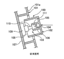
- the operation knob support structure 100 illustrated in FIG. 1 includes a support portion 103 that supports the operation knob 102 so as to be displaceable with respect to the device main body 101 of the electronic device described above, and a fragile portion 104.
- the operation knob 102 is integrally provided with a knob main body 105 formed in a bottomed cylindrical shape and a cylindrical cylindrical portion 106 erected from the bottom of the knob main body 105.
- the front surface 101a of the device main body 101 is parallel to the surface of the instrument panel.
- the support unit 103 includes a printed wiring board 107 housed in the device main body 101 and fixed in parallel with the front surface 101 a of the device main body 101, and a switch device 108 mounted on the printed wiring board 107.
- the switch device 108 includes a switch main body 109 fixed to the printed wiring board 107, and an operation element 110 that protrudes from the switch main body 109 and is displaceable in a rotating direction and a retracting direction with respect to the switch main body 109.
- the operation element 110 is formed in a columnar shape, and is press-fitted into the above-described cylinder portion 106, and the operation knob 102 is attached thereto.
- the operation knob 102 is displaceable with respect to the device main body 101 in a direction that rotates around its axis by the operation element 110 and a direction that protrudes and retracts from the front surface 101a. Further, the operation knob 102 looks orthogonal to the front surface 101a of the device main body 101.
- an object of the present invention is that, for example, when a predetermined force is applied when the main body is attached to an instrument panel whose surface is inclined, the weakened portion is broken and the operation knob can be sunk. It is an object of the present invention to provide an operation knob support structure and an electronic apparatus including the operation knob support structure.
- the AV device 1 receives a case 2 as a main unit, a CD (Compact Disk) player 3 as a playback apparatus, an MD (Mini Disc) player 4 as a playback apparatus, and a radio broadcast.
- the angles of the surface Pa of the instrument panel P and the front surface 2a of the front panel 18a with respect to the vertical direction are determined in advance. It has been established. Further, a CD insertion slot 8, an MD insertion slot 9, and an operation section hole 13 are opened in the front surface 2a of the front panel 18a.
- the CD insertion slot 8 passes the CD inside, and puts the CD in and out of the case 2, that is, the CD player 3.
- the MD insertion port 9 passes the MD inward, and puts the MD in and out of the case 2, that is, the MD player 4.
- the operation portion hole 13 passes through the front panel 18a.
- the operation portion hole 13, that is, the front panel 18a accommodates an operation button 11 to be described later of the operation portion 7, and supports the operation button 11 movably along a depth direction Y orthogonal to the front surface 2a. .
- the case 2 is provided with a hole 14, a support portion 16, and an internal wall 17.
- the hole 14 is open to the front surface 2a and has a round planar shape.
- the support portion 16 includes an inner cylinder portion 19 and a hinge support portion 20.
- the inner cylinder portion 19 is formed in a cylindrical shape and is erected from the inner edge portion of the hole 14 toward the inside of the case 2.
- locking part 22 is weaker than the predetermined
- a force F indicated by an arrow in FIG. 5
- the locking portion main body 26 is displaced toward the inner cylindrical portion 19 and the locking claw 27, that is, the supporting portion.
- the other end 35b of the holder main body 35 of the substrate holder 32 is released.
- the printed wiring board 33 on which the switch device 34 is mounted is attached to the holder main body 35 of the substrate holder 32, and the hinge shaft 36 of the substrate holder 32 is passed through the hole 21 of the hinge support portion 20.
- the locking claws 27 and 39 of the locking portions 22 and 37 are locked together and assembled.
- the operation knob 15 is attached to the operation element 41 of the switch device 34.
- the front surfaces of the printed wiring board 33 and the holder main body 35 of the substrate holder 32 are parallel to the front surface 2a of the front panel 18a, and the one end 35a is more forward than the other end 35b.
- the printed wiring board 33, that is, the substrate holder 32 is arranged to be inclined with respect to the vertical direction.
- the protrusion 42 of the fragile portion 25 is broken from the inner peripheral surface of the cylindrical portion 31 of the operation knob 15 as shown in FIG. Then, the operating element 41 slides in the cylindrical portion 31, and the operating knob 15 moves in the direction of sunk in the hole 14, that is, in the front surface 2a. As shown in FIG. 42 and the bottom 28 are in intimate contact. Then, of course, the protruding amount T (shown in FIG. 8) of the operation knob 15 from the front surface 2a is less than the predetermined value described above.
- An operation knob 15 that protrudes from the front surface 2a of the case 2 and is disposed so as to be displaceable with respect to the case 2 is inclined with respect to the vertical direction;
- a substrate holder 32 on which the switch device 34 is installed and one end 35a is attached to the case 2, If the operation knob 15 is provided between the switch device 34 and the operation knob 15 and is pressed with a force exceeding a predetermined force toward the front surface 2a along the horizontal direction, it breaks.
- Vulnerable part 25 Due to the predetermined force that is provided on the case 2 and engages with the other end portion 35b of the substrate holder 32, and the operation knob 15 breaks the fragile portion 25 toward the front surface 2a along the horizontal direction.
- a locking portion 22 that releases the locking of the other end portion 35b when pressed with a force exceeding the weak second predetermined force, When the locking of the other end portion 35b of the locking portion 22 is released, the substrate comes into contact with the substrate holder 32 so that the outer surface 28a of the operation knob 15 is parallel to the vertical direction.
- the switch device 34 supporting the operation knob 15 is installed on the substrate holder 32 whose one end 35 a is attached to the front panel 18 a, and the fragile portion 25 is provided between the switch device 34 and the operation knob 15.
- the other end portion 35 b of the substrate holder 32 is attached to the front panel 18 a by the locking portion 22.
- the operation knob 15 is pressed with a force exceeding a second predetermined force that is weaker than a predetermined force that breaks the fragile portion 25 toward the front surface 2a of the front panel 18a along the front-rear direction (horizontal direction) of the automobile. Then, the locking of the locking portion 22 is released, and the substrate holder 32 is positioned by the stopper member 24 so that the outer surface 28a of the bottom portion 28 of the operation knob 15 is parallel to the vertical direction.
- the outer surface 28a of the operation knob 15 is positioned in a state parallel to the vertical direction before the fragile portion 25 is broken, and when the fragile portion 25 is broken, the operation knob 15 is switched to the switch device. 34 does not tilt. Therefore, when the fragile portion 25 breaks, the force that the outer surface 28a presses the operation knob 15 parallel to the vertical direction along the horizontal direction toward the front surface 2a of the front panel 18a surely acts. . Therefore, the fragile portion 25 is surely broken when a predetermined predetermined force acts on the operation knob 15, and the operation knob 15 is surely secured until the projection amount T from the case 2 becomes a predetermined value or less. It will be sunk with respect to the front panel 18a.
Landscapes
- Physics & Mathematics (AREA)
- General Physics & Mathematics (AREA)
- Engineering & Computer Science (AREA)
- Automation & Control Theory (AREA)
- Instrument Panels (AREA)
- Switches With Compound Operations (AREA)
- Switch Cases, Indication, And Locking (AREA)
- Fittings On The Vehicle Exterior For Carrying Loads, And Devices For Holding Or Mounting Articles (AREA)
- Rotary Switch, Piano Key Switch, And Lever Switch (AREA)
Abstract
Priority Applications (3)
| Application Number | Priority Date | Filing Date | Title |
|---|---|---|---|
| PCT/JP2007/074934 WO2009081493A1 (fr) | 2007-12-26 | 2007-12-26 | Structure de support de bouton de fonction et équipement électronique comprenant la structure de support du bouton de fonction |
| CN200780101211.2A CN101836278A (zh) | 2007-12-26 | 2007-12-26 | 操作旋钮的支承结构及具备该操作旋钮的支承结构的电子设备 |
| JP2009546909A JP4967030B2 (ja) | 2007-12-26 | 2007-12-26 | 操作ノブの支持構造及び該操作ノブの支持構造を備えた電子機器 |
Applications Claiming Priority (1)
| Application Number | Priority Date | Filing Date | Title |
|---|---|---|---|
| PCT/JP2007/074934 WO2009081493A1 (fr) | 2007-12-26 | 2007-12-26 | Structure de support de bouton de fonction et équipement électronique comprenant la structure de support du bouton de fonction |
Publications (1)
| Publication Number | Publication Date |
|---|---|
| WO2009081493A1 true WO2009081493A1 (fr) | 2009-07-02 |
Family
ID=40800811
Family Applications (1)
| Application Number | Title | Priority Date | Filing Date |
|---|---|---|---|
| PCT/JP2007/074934 Ceased WO2009081493A1 (fr) | 2007-12-26 | 2007-12-26 | Structure de support de bouton de fonction et équipement électronique comprenant la structure de support du bouton de fonction |
Country Status (3)
| Country | Link |
|---|---|
| JP (1) | JP4967030B2 (fr) |
| CN (1) | CN101836278A (fr) |
| WO (1) | WO2009081493A1 (fr) |
Cited By (1)
| Publication number | Priority date | Publication date | Assignee | Title |
|---|---|---|---|---|
| EP2518902A1 (fr) * | 2011-04-26 | 2012-10-31 | Technisat Digital Gmbh | Elément de commande pour un véhicule automobile |
Families Citing this family (3)
| Publication number | Priority date | Publication date | Assignee | Title |
|---|---|---|---|---|
| JP6209004B2 (ja) * | 2013-07-23 | 2017-10-04 | 株式会社ユーシン | 車両用空調操作装置。 |
| CN108172427A (zh) * | 2018-01-13 | 2018-06-15 | 深圳佳比泰智能照明股份有限公司 | 面板开关 |
| JP7349925B2 (ja) * | 2020-02-04 | 2023-09-25 | 株式会社東海理化電機製作所 | スイッチ装置 |
Citations (3)
| Publication number | Priority date | Publication date | Assignee | Title |
|---|---|---|---|---|
| JPH0439608U (fr) * | 1990-08-01 | 1992-04-03 | ||
| JPH0583817U (ja) * | 1992-03-31 | 1993-11-12 | 株式会社ケンウッド | ツマミ構造 |
| JP2006210288A (ja) * | 2005-01-31 | 2006-08-10 | Fujitsu Ten Ltd | 突出量変位構造、ノブ構造および突出量変位方法 |
-
2007
- 2007-12-26 CN CN200780101211.2A patent/CN101836278A/zh active Pending
- 2007-12-26 WO PCT/JP2007/074934 patent/WO2009081493A1/fr not_active Ceased
- 2007-12-26 JP JP2009546909A patent/JP4967030B2/ja not_active Expired - Fee Related
Patent Citations (3)
| Publication number | Priority date | Publication date | Assignee | Title |
|---|---|---|---|---|
| JPH0439608U (fr) * | 1990-08-01 | 1992-04-03 | ||
| JPH0583817U (ja) * | 1992-03-31 | 1993-11-12 | 株式会社ケンウッド | ツマミ構造 |
| JP2006210288A (ja) * | 2005-01-31 | 2006-08-10 | Fujitsu Ten Ltd | 突出量変位構造、ノブ構造および突出量変位方法 |
Cited By (1)
| Publication number | Priority date | Publication date | Assignee | Title |
|---|---|---|---|---|
| EP2518902A1 (fr) * | 2011-04-26 | 2012-10-31 | Technisat Digital Gmbh | Elément de commande pour un véhicule automobile |
Also Published As
| Publication number | Publication date |
|---|---|
| CN101836278A (zh) | 2010-09-15 |
| JP4967030B2 (ja) | 2012-07-04 |
| JPWO2009081493A1 (ja) | 2011-05-06 |
Similar Documents
| Publication | Publication Date | Title |
|---|---|---|
| US5953302A (en) | Recorded medium playback device with removable panel and having a lever contacting panel and detection switch | |
| CN101456386B (zh) | 车载用电子装置 | |
| JP4967030B2 (ja) | 操作ノブの支持構造及び該操作ノブの支持構造を備えた電子機器 | |
| CN100358750C (zh) | 车载用电子设备 | |
| JP2003308686A (ja) | 電子機器 | |
| US6747364B1 (en) | Electronic device having retractable movable member provided on front surface | |
| JP4139709B2 (ja) | 電子機器 | |
| WO2017169075A1 (fr) | Dispositif embarqué et dispositif de fixation d'affichage | |
| JP5006943B2 (ja) | 操作ノブの支持構造及び該操作ノブの支持構造を備えた電子機器 | |
| JP2008189031A (ja) | 車載用電子機器 | |
| JPH10199220A (ja) | 記録媒体再生装置及びその制御方法 | |
| KR20010106213A (ko) | 자동차의 중앙 콘솔등의 설치 개구부에 기구를 빨리고정시키기 위한 장치 | |
| JP2011018453A (ja) | 操作ノブの支持構造及び該操作ノブの支持構造を備えた電子機器 | |
| EP1666312B1 (fr) | Panneau pour intérieur véhicule absorbant un impact | |
| JP4264023B2 (ja) | 車載機器 | |
| JP2008192449A (ja) | 押しボタン構造および電子機器 | |
| JP2008226350A (ja) | 電子機器 | |
| JP2006131039A (ja) | 自動車の車体構造 | |
| KR200314096Y1 (ko) | 자동차용 콤비네이션 스위치 | |
| JP2005209506A (ja) | 車載用押しボタンスイッチ | |
| JPH09233405A (ja) | 車載用ディスプレイの収納装置 | |
| JP2019182060A (ja) | 車載装置 | |
| KR100514081B1 (ko) | 자동차용 콤비네이션 스위치 | |
| JPH09188202A (ja) | 車載用音響映像装置 | |
| KR100246042B1 (ko) | 자동차용 오디오 시스템 |
Legal Events
| Date | Code | Title | Description |
|---|---|---|---|
| WWE | Wipo information: entry into national phase |
Ref document number: 200780101211.2 Country of ref document: CN |
|
| 121 | Ep: the epo has been informed by wipo that ep was designated in this application |
Ref document number: 07860163 Country of ref document: EP Kind code of ref document: A1 |
|
| WWE | Wipo information: entry into national phase |
Ref document number: 2009546909 Country of ref document: JP |
|
| NENP | Non-entry into the national phase |
Ref country code: DE |
|
| 122 | Ep: pct application non-entry in european phase |
Ref document number: 07860163 Country of ref document: EP Kind code of ref document: A1 |