WO2017169075A1 - Dispositif embarqué et dispositif de fixation d'affichage - Google Patents
Dispositif embarqué et dispositif de fixation d'affichage Download PDFInfo
- Publication number
- WO2017169075A1 WO2017169075A1 PCT/JP2017/003526 JP2017003526W WO2017169075A1 WO 2017169075 A1 WO2017169075 A1 WO 2017169075A1 JP 2017003526 W JP2017003526 W JP 2017003526W WO 2017169075 A1 WO2017169075 A1 WO 2017169075A1
- Authority
- WO
- WIPO (PCT)
- Prior art keywords
- display
- main body
- electrical connector
- cover
- apparatus main
- Prior art date
- Legal status (The legal status is an assumption and is not a legal conclusion. Google has not performed a legal analysis and makes no representation as to the accuracy of the status listed.)
- Ceased
Links
Images









Classifications
-
- B—PERFORMING OPERATIONS; TRANSPORTING
- B60—VEHICLES IN GENERAL
- B60R—VEHICLES, VEHICLE FITTINGS, OR VEHICLE PARTS, NOT OTHERWISE PROVIDED FOR
- B60R11/00—Arrangements for holding or mounting articles, not otherwise provided for
- B60R11/02—Arrangements for holding or mounting articles, not otherwise provided for for radio sets, television sets, telephones, or the like; Arrangement of controls thereof
- B60R11/0229—Arrangements for holding or mounting articles, not otherwise provided for for radio sets, television sets, telephones, or the like; Arrangement of controls thereof for displays, e.g. cathodic tubes
- B60R11/0235—Arrangements for holding or mounting articles, not otherwise provided for for radio sets, television sets, telephones, or the like; Arrangement of controls thereof for displays, e.g. cathodic tubes of flat type, e.g. LCD
-
- B—PERFORMING OPERATIONS; TRANSPORTING
- B60—VEHICLES IN GENERAL
- B60K—ARRANGEMENT OR MOUNTING OF PROPULSION UNITS OR OF TRANSMISSIONS IN VEHICLES; ARRANGEMENT OR MOUNTING OF PLURAL DIVERSE PRIME-MOVERS IN VEHICLES; AUXILIARY DRIVES FOR VEHICLES; INSTRUMENTATION OR DASHBOARDS FOR VEHICLES; ARRANGEMENTS IN CONNECTION WITH COOLING, AIR INTAKE, GAS EXHAUST OR FUEL SUPPLY OF PROPULSION UNITS IN VEHICLES
- B60K35/00—Instruments specially adapted for vehicles; Arrangement of instruments in or on vehicles
- B60K35/10—Input arrangements, i.e. from user to vehicle, associated with vehicle functions or specially adapted therefor
-
- B—PERFORMING OPERATIONS; TRANSPORTING
- B60—VEHICLES IN GENERAL
- B60K—ARRANGEMENT OR MOUNTING OF PROPULSION UNITS OR OF TRANSMISSIONS IN VEHICLES; ARRANGEMENT OR MOUNTING OF PLURAL DIVERSE PRIME-MOVERS IN VEHICLES; AUXILIARY DRIVES FOR VEHICLES; INSTRUMENTATION OR DASHBOARDS FOR VEHICLES; ARRANGEMENTS IN CONNECTION WITH COOLING, AIR INTAKE, GAS EXHAUST OR FUEL SUPPLY OF PROPULSION UNITS IN VEHICLES
- B60K35/00—Instruments specially adapted for vehicles; Arrangement of instruments in or on vehicles
- B60K35/20—Output arrangements, i.e. from vehicle to user, associated with vehicle functions or specially adapted therefor
- B60K35/21—Output arrangements, i.e. from vehicle to user, associated with vehicle functions or specially adapted therefor using visual output, e.g. blinking lights or matrix displays
- B60K35/22—Display screens
-
- B—PERFORMING OPERATIONS; TRANSPORTING
- B60—VEHICLES IN GENERAL
- B60K—ARRANGEMENT OR MOUNTING OF PROPULSION UNITS OR OF TRANSMISSIONS IN VEHICLES; ARRANGEMENT OR MOUNTING OF PLURAL DIVERSE PRIME-MOVERS IN VEHICLES; AUXILIARY DRIVES FOR VEHICLES; INSTRUMENTATION OR DASHBOARDS FOR VEHICLES; ARRANGEMENTS IN CONNECTION WITH COOLING, AIR INTAKE, GAS EXHAUST OR FUEL SUPPLY OF PROPULSION UNITS IN VEHICLES
- B60K35/00—Instruments specially adapted for vehicles; Arrangement of instruments in or on vehicles
- B60K35/50—Instruments characterised by their means of attachment to or integration in the vehicle
-
- B—PERFORMING OPERATIONS; TRANSPORTING
- B60—VEHICLES IN GENERAL
- B60R—VEHICLES, VEHICLE FITTINGS, OR VEHICLE PARTS, NOT OTHERWISE PROVIDED FOR
- B60R11/00—Arrangements for holding or mounting articles, not otherwise provided for
- B60R11/02—Arrangements for holding or mounting articles, not otherwise provided for for radio sets, television sets, telephones, or the like; Arrangement of controls thereof
-
- H—ELECTRICITY
- H04—ELECTRIC COMMUNICATION TECHNIQUE
- H04N—PICTORIAL COMMUNICATION, e.g. TELEVISION
- H04N5/00—Details of television systems
- H04N5/64—Constructional details of receivers, e.g. cabinets or dust covers
-
- H—ELECTRICITY
- H04—ELECTRIC COMMUNICATION TECHNIQUE
- H04N—PICTORIAL COMMUNICATION, e.g. TELEVISION
- H04N5/00—Details of television systems
- H04N5/64—Constructional details of receivers, e.g. cabinets or dust covers
- H04N5/655—Construction or mounting of chassis, e.g. for varying the elevation of the tube
-
- B—PERFORMING OPERATIONS; TRANSPORTING
- B60—VEHICLES IN GENERAL
- B60K—ARRANGEMENT OR MOUNTING OF PROPULSION UNITS OR OF TRANSMISSIONS IN VEHICLES; ARRANGEMENT OR MOUNTING OF PLURAL DIVERSE PRIME-MOVERS IN VEHICLES; AUXILIARY DRIVES FOR VEHICLES; INSTRUMENTATION OR DASHBOARDS FOR VEHICLES; ARRANGEMENTS IN CONNECTION WITH COOLING, AIR INTAKE, GAS EXHAUST OR FUEL SUPPLY OF PROPULSION UNITS IN VEHICLES
- B60K2360/00—Indexing scheme associated with groups B60K35/00 or B60K37/00 relating to details of instruments or dashboards
- B60K2360/40—Hardware adaptations for dashboards or instruments
- B60K2360/46—Electrical connections
-
- B—PERFORMING OPERATIONS; TRANSPORTING
- B60—VEHICLES IN GENERAL
- B60R—VEHICLES, VEHICLE FITTINGS, OR VEHICLE PARTS, NOT OTHERWISE PROVIDED FOR
- B60R11/00—Arrangements for holding or mounting articles, not otherwise provided for
- B60R2011/0001—Arrangements for holding or mounting articles, not otherwise provided for characterised by position
- B60R2011/004—Arrangements for holding or mounting articles, not otherwise provided for characterised by position outside the vehicle
Definitions
- the present disclosure relates to an in-vehicle device mounted on a vehicle, and particularly to an in-vehicle device provided with a display having a screen size larger than the front size of the device body.
- an in-vehicle device having a display with a screen size larger than the front size of the device body has been proposed.
- the reproducing apparatus main body is embedded in a 2DIN size box in the console, and an image display apparatus having a size of 7 inches or more is detachable from the reproducing apparatus main body. Is attached.
- the information reproducing apparatus can be freely sized and shaped.
- the in-vehicle device includes a device main body and a display.
- the apparatus main body is stored in a storage box provided on the console panel of the vehicle.
- the display is detachably attached to the apparatus main body.
- the display has a display-side electrical connector having a plurality of connection terminals.
- the apparatus main body includes an apparatus main body-side electrical connector, a substrate, a switch, and a blind cover.
- the apparatus main body side electrical connector is provided so as to protrude from the front of the apparatus main body, and is detachable from the display side electric connector.
- the board supports the apparatus main body side electrical connector.
- the switch is provided on the substrate and switches between an energized state and a non-energized state of the apparatus main body side electrical connector.
- the blindfold cover is attached so as to cover a connecting portion between the apparatus main body side electrical connector and the display side electric connector.
- the blindfold cover has a protrusion configured to press the switch to switch the apparatus main body side electrical connector from the non-energized state to the energized state when attached so as to cover the connecting portion.
- the safety when the display is attached to the device main body can be improved.
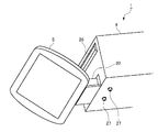
- FIG. 1 is a perspective view showing an in-vehicle device (attached state) in the embodiment.
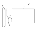
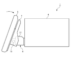
- FIG. 2 is a side view of the in-vehicle device according to the embodiment.
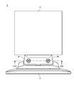
- FIG. 3 is a rear view of the display and the display cover in the embodiment.
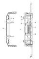
- FIG. 4 is an explanatory diagram showing the internal structure of the display cover in the embodiment.
- FIG. 5 is a side sectional view showing a lock mechanism (locked state) in the embodiment.
- FIG. 6 is a side sectional view showing a lock mechanism (unlocked state) in the embodiment.
- FIG. 7 is an explanatory diagram of the vertical slide of the display in the embodiment.
- FIG. 8 is an explanatory diagram of the vertical slide of the display in the embodiment.
- FIG. 9 is an explanatory diagram of tilt rotation of the display in the embodiment.
- FIG. 10 is an explanatory diagram of tilt rotation of the display in the embodiment.
- FIG. 11 is a perspective view of the connecting portion in the embodiment as viewed from below.
- FIG. 12 is an exploded perspective view of the connecting portion in the embodiment as viewed from below.
- FIG. 13 is an explanatory diagram of the front / rear slide of the display in the embodiment.
- FIG. 14 is an explanatory diagram of the front / rear slide of the display in the embodiment.
- FIG. 15 is an exploded perspective view of the connecting portion in the embodiment as viewed from the upper side and the display side.
- FIG. 16 is an exploded perspective view of the connecting portion in the embodiment as viewed from the upper side and the apparatus main body side.
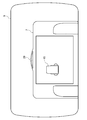
- FIG. 17 is a plan view showing the in-vehicle device (attached state) in the embodiment.
- 18 is an exploded cross-sectional view taken along the line XIX-XIX of the connecting portion of the in-vehicle apparatus shown in FIG.
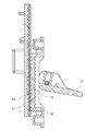
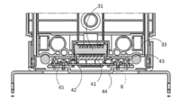
- FIG. 19 is a cross-sectional view taken along line XIX-XIX of the connecting portion of the in-vehicle device shown in FIG. 20 is a cross-sectional view of the connecting portion of the in-vehicle device shown in FIG. 17 cut along a plane parallel to the paper surface.
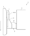
- FIG. 21 is an enlarged view of a region surrounded by a one-dot chain line denoted by reference character B in FIG.
- the electrical connection part is provided so as to protrude from the front of the apparatus main body, the connection state of the electrical connection part can be visually confirmed when the image display device is attached to the playback apparatus main body, but the electrical connection part is erroneously connected. There is a risk of electric shock when touched. In addition, when a large vibration is generated in the vehicle, a large load is applied to the electrical connection portion, which may cause a disconnection.
- the present disclosure provides an in-vehicle device with improved safety when a display is attached to a device body.
- an in-vehicle device according to an embodiment of the present disclosure will be described with reference to the drawings.
- a case of an in-vehicle device used as a video playback device, a music playback device, a navigation device or the like mounted on a car will be exemplified.
- FIG. 1 is a perspective view of the in-vehicle device of the present embodiment
- FIG. 2 is a side view of the in-vehicle device of the present embodiment.
- the in-vehicle device 1 is attached to a storage box 3 of a console panel 2 of the vehicle.
- the size of the storage box 3 is, for example, 2DIN size.
- the in-vehicle device 1 includes a device main body 4 and a display 5 that is detachably attached to the device main body 4.
- the apparatus body 4 is stored in a storage box 3 of the console panel 2.
- the display 5 has a screen size larger than the front size (2DIN size) of the apparatus body 4.
- the screen size of the display 5 is, for example, 9 inches.
- a display cover 7 is attached to the back of the display 5.
- the display cover 7 includes a vertical slide mechanism that slides the display 5 in the vertical direction of the screen.
- FIG. 3 is a rear view of the display 5 and the display cover 7, and
- FIG. 4 is an explanatory view showing the internal structure of the display cover 7.
- the display cover 7 includes a vertical slide base 8 and a vertical slide member 9.
- the vertical slide base 8 has a vertical slide rail 10 extending in the vertical direction of the screen, and the vertical slide member 9 is slidably attached to the vertical slide rail 10.
- the left and right sides of the vertical slide member 9 (left and right sides in FIG. 4) are held by the pair of left and right vertical slide rails 10.
- the vertical slide member 9 is fixed to the display 5.
- the display cover 7 has a lock mechanism that locks the slide movement of the display 5.
- 5 and 6 are side cross-sectional views for explaining the locking mechanism.
- the vertical slide member 9 includes a rack base 11, and the vertical slide base 8 includes a rack gear 12.
- the rack base 11 is formed with a first engaging portion 13
- the rack gear 12 is formed with a second engaging portion 14.
- the rack gear 12 is configured to be pressed against the rack base 11 by rotating the knob 15 so as to raise the knob 15 (counterclockwise in FIG. 5).
- the rack gear 12 is pressed against the rack base 11, the first engaging portion 13 and the second engaging portion 14 are engaged, and the sliding movement of the upper and lower slide member 9 relative to the upper and lower slide base 8 is locked. In this way, the slide movement of the display 5 is locked.
- the rack gear 12 is configured such that the pressing against the rack base 11 is loosened by turning the knob 15 so as to tilt (clockwise in FIG. 6).
- the first engagement portion 13 and the second engagement portion 14 are disengaged, and the slide movement lock of the upper and lower slide member 9 with respect to the upper and lower slide base 8 is released. The In this way, the slide movement lock of the display 5 is released.
- the vertical slide member 9 includes an engaged gear 16 that extends in the vertical direction of the screen, and the vertical slide base 8 includes a damper gear 17 that engages with the engaged gear 16. Yes.
- the rack base 11 and the rack gear 12 are arranged on one of the left and right sides of the display 5 (left side in FIG. 4), and the engaged gear 16 and the damper gear 17 are on the left and right sides of the display 5. It is arranged on the other side (the right side in FIG. 4).
- the knob 15 When sliding the display 5 upward on the screen, the knob 15 is tilted to release the lock, and the user pushes the display 5 up manually. Then, the vertical slide member 9 slides upward with respect to the vertical slide rail 10, and the display 5 slides and moves upward on the screen (see FIG. 7). At this time, the display 5 slowly slides upward on the screen due to the action of the damper gear 17. When the slide movement of the display 5 is completed, the knob 15 is raised to lock the slide movement.
- the knob 15 is tilted to release the lock, and the user manually pulls down the display 5. Then, the vertical slide member 9 slides downward with respect to the vertical slide rail 10, and the display 5 slides and moves downward on the screen (see FIG. 8). At this time, the display 5 slowly slides downward in the screen due to the action of the damper gear 17. When the slide movement of the display 5 is completed, the knob 15 is raised to lock the slide movement.
- the display cover 7 includes a tilt mechanism that rotates the display 5 in the tilt direction.
- 9 and 10 are explanatory diagrams of tilt rotation of the display 5.
- the apparatus main body 4 includes a front / rear slide moving mechanism for sliding the display 5 in the front / rear direction with respect to the apparatus main body 4.
- FIG. 11 is a perspective view of the connecting portion 6 between the display 5 and the apparatus main body 4 as viewed from below
- FIG. 12 is an exploded perspective view of the connecting portion 6 as viewed from below.
- 13 and 14 are explanatory diagrams of the front / rear slide of the display 5.
- the apparatus main body 4 includes a front / rear slide member 19 connected to the display cover 7. Most of the front / rear slide member 19 is housed inside the apparatus main body 4, and a part projects from the apparatus main body 4 to the outside. Here, a portion protruding from the apparatus main body 4 to the outside is referred to as a neck portion 20. A blindfold cover 21 is attached to the neck portion 20 from above.
- a front / rear slide base 23 is accommodated in the bottom of the apparatus body 4.
- the front / rear slide base 23 includes a front / rear slide rail 24 extending in the front / rear direction of the apparatus main body 4 (left / right direction in FIGS. 13 and 14), and the front / rear slide member 19 is slidably attached to the front / rear slide rail 24.
- the left and right sides of the front and rear slide member 19 are held by a pair of left and right front and rear slide rails 24.
- a pair of left and right screw receiving grooves 25 extending in the front-rear direction of the apparatus main body 4 (left and right directions in FIGS. 13 and 14) are formed on the lower surface of the neck portion 20.
- the display 5 is fixed so as not to slide back and forth by screwing the fixing screw 27 through the screw hole 26.
- the fixing screw 27 is removed to release the fixing, and the user manually pushes the display 5. Then, the front / rear slide member 19 slides backward with respect to the front / rear slide rail 24, and the display 5 slides backward (see FIG. 13). When the slide movement of the display 5 is completed, the fixing screw 27 is screwed and fixed so as not to slide.
- the fixing screw 27 When sliding the display 5 forward (frontward, leftward in FIG. 14), the fixing screw 27 is removed to release the fixing, and the user manually pulls the display 5 out. Then, the front / rear slide member 19 slides forward with respect to the front / rear slide rail 24, and the display 5 slides forward (see FIG. 14). When the slide movement of the display 5 is completed, the fixing screw 27 is screwed and fixed so as not to slide.
- FIG. 15 is an exploded perspective view of the connecting portion 6 viewed from the upper side and the display 5 side
- FIG. 16 is an exploded perspective view of the connecting portion 6 viewed from the upper side and the apparatus main body 4 side.
- FIG. 17 is a plan view showing the in-vehicle device 1 (attached state). 18 is an exploded cross-sectional view taken along the line XIX-XIX of the connecting portion 6 of the in-vehicle device 1 shown in FIG. 17, and FIG. 19 is a cross-sectional view taken along the line XIX-XIX of the connecting portion 6 of the in-vehicle device 1 shown in FIG.
- FIG. 20 is a cross-sectional view of the connecting portion of the in-vehicle device shown in FIG. 17 cut along a plane parallel to the paper surface.
- FIG. 21 is an enlarged view of a region surrounded by a one-dot chain line denoted by reference character B in FIG.
- the display 5 is made of a display side electrical connector 41 having a plurality of connection terminals, a display side substrate 42 that supports the display side electrical connector 41, and a resin that covers the display side substrate 42.
- the display-side electrical connector 41 for example, a commercially available floating connector is used.
- the plurality of connection terminals of the display-side electrical connector 41 include both power connection terminals and signal connection terminals.
- a through-hole is formed in the display-side substrate 42, and the display-side substrate cover 43 has a convex portion that is inserted into the through-hole of the display-side substrate 42. Then, with the tip of the convex portion of the display-side substrate cover 43 in contact with the sheet metal 44, a screw 45 is screwed so as to penetrate the convex portion and the sheet metal 44.
- the height of the convex portion of the display side substrate cover 43 is larger than the thickness of the display side substrate 42. Therefore, in a state where the display side substrate cover 43 is screwed to the sheet metal 44, a gap S ⁇ b> 1 is provided in the axial direction of the screw 45 between the display side substrate 42 and the display side substrate cover 43.
- the outer diameter of the convex portion of the display side substrate cover 43 is smaller than the inner diameter of the through hole of the display side substrate 42. Therefore, in a state where the display side substrate cover 43 is screwed to the sheet metal 44, a direction perpendicular to the axial direction of the screw 45 (the display side substrate 42) is between the display side substrate 42 and the display side substrate cover 43. Is also provided in the surface direction).
- the apparatus body 4 includes an apparatus body side electrical connector 31 that can be attached to and detached from the display side electrical connector 41, a substrate 32 that supports the apparatus body side electrical connector 31, A substrate cover 33 that covers the substrate 32 and a switch 34 that is provided on the substrate 32 and switches between energization and non-energization of the apparatus main body side electrical connector 31 are provided.
- the device main body side electrical connector 31 is provided so as to protrude from the front surface of the device main body 4, and in the illustrated example, provided on the neck portion 20 described above. Since the apparatus main body side electrical connector 31 is provided so as to protrude from the front surface of the apparatus main body 4, this connection state can be easily confirmed visually when connecting to the display side electric connector 41. Thereby, it can prevent using the vehicle-mounted apparatus 1 with a connection state incomplete.
- the switch 34 is a lever type switch, for example, and has a lever extending obliquely upward with respect to the substrate 32.
- the lever of the switch 34 When the lever of the switch 34 is pressed downward and pushed down to the substrate 32 side, energization to the apparatus main body side electrical connector 31 is started, and electricity is supplied from the apparatus main body side electric connector 31 to the display side electric connector 41. .
- the downward pressure on the lever of the switch 34 is eliminated, the restoring force of the lever itself returns to the original angle, the power supply to the apparatus main body side electrical connector 31 is stopped, and the display from the apparatus main body side electrical connector 31 is displayed. Supply of electricity to the side electrical connector 41 is stopped.
- the above-described blindfold cover 21 is attached so as to cover a connecting portion between the apparatus main body side electrical connector 31 and the display side electrical connector 41, and is fixed by screws 38.
- the blindfold cover 21 has a boss 35 (protrusion) that presses the switch 34 to switch the apparatus main body side electrical connector 31 to the energized state when attached so as to cover the connecting portion. is doing.
- the boss 35 is provided so as to extend downward from the inside of the blindfold cover 21.
- the boss 35 is provided with a rib 37 extending in the axial direction (projection direction).
- the four ribs 37 are provided at an angular position forming 90 ° with each other, and the cross-sectional shape of the boss 35 has a cross shape. Since the boss 35 has the rib 37, the strength of the boss 35 is improved, and the boss 35 is prevented from being accidentally hit against the substrate cover 33 and the like when the blind cover 21 is attached.
- the boss 35 of the blind cover 21 causes the switch 34 to be switched.
- the device main body side electrical connector 31 is switched to the energized state by pressing. For this reason, when the display-side electrical connector 41 is connected to the apparatus main body side electrical connector 31, electricity is not yet supplied to the apparatus main body side electrical connector 31, and the hand touches the apparatus main body side electrical connector 31 by mistake. There is no electric shock. Therefore, the operation of attaching the display 5 to the apparatus main body 4 can be performed extremely safely.
- the substrate cover 33 is provided with a cylindrical guide portion 36 for guiding the boss 35.
- the cross-sectional shape of the guide portion 36 is not particularly limited, and may be a circular shape or an arc shape with a part cut away.
- the switch 34 on the substrate 32 is positioned at the tip of the guide portion 36. Thereby, when the blindfold cover 21 is attached so as to cover the connecting portion, the boss 35 of the blindfold cover 21 is guided toward the switch 34 by the guide portion 36 of the substrate cover 33. Thereby, the situation where the pressing position of the boss 35 is removed from the switch 34 and the apparatus main body side electrical connector 31 is not switched to the energized state is avoided.
- a gap S1 is provided between the display side substrate 42 and the display side substrate cover 43 in the axial direction of the screw 45 (vertical direction in FIG. 21). Therefore, when a large vibration is generated in the vehicle, the display-side board 42 can move together with the display-side electrical connector 41 by the size of the gap S1 in the axial direction of the screw 45 with respect to the display-side board cover 43. As a result, the load applied to the display-side electrical connector 41 and the device main body-side electrical connector 31 connected thereto is alleviated, and disconnection of the display-side electric connector 41 and the device main-unit side electrical connector 31 is prevented.
- a gap S2 is provided between the display side substrate 42 and the display side substrate cover 43 in a direction perpendicular to the axial direction of the screw 45 (left and right direction in FIG. 21).
- the blindfold cover 21 is attached to cover the connection portion.
- the boss 35 of the cover 21 presses the switch 34 to switch the apparatus main body side electrical connector 31 to the energized state. Therefore, when the display-side electrical connector 41 is connected to the apparatus main body side electrical connector 31, even if the hand is accidentally touched with the apparatus main body side electrical connector 31, there is no electric shock and it is extremely safe.
- the apparatus main body side electrical connector 31 is provided so as to protrude from the front of the apparatus main body 4, the connection state with the display side electric connector 41 can be visually confirmed, and the connection state is incomplete. It can prevent using the vehicle-mounted apparatus 1 as it is.
- the gap S1 is opened in the axial direction of the screw 45 between the display side substrate 42 and the display side substrate cover 43, when a large vibration occurs in the vehicle.
- the display-side substrate 42 can move with the display-side electrical connector 41 relative to the display-side substrate cover 43 in the axial direction of the screw 45 by the size of the gap S1.
- the load applied to the display-side electrical connector 41 and the device main body-side electrical connector 31 connected thereto is alleviated, and disconnection of the display-side electric connector 41 and the device main-unit side electrical connector 31 is prevented.
- the gap S2 is opened between the display side substrate 42 and the display side substrate cover 43 in a direction perpendicular to the axial direction of the screw 45, which is large for the vehicle.
- the display side substrate 42 can move by the size of the gap S2 in the direction perpendicular to the axial direction of the screw 45 with respect to the display side substrate cover 43 together with the display side electrical connector 41.
- the load applied to the display side electrical connector 41 and the apparatus main body side electrical connector 31 is further alleviated, and it is more reliably prevented that the display side electrical connector 41 and the apparatus body side electrical connector 31 are disconnected.
- the switch 34 is positioned at the tip of the guide portion 36 that guides the boss 35, the boss 35 of the blindfold cover 21 is attached when the blindfold cover 21 is attached so as to cover the connecting portion. Is guided toward the switch 34 by the guide portion 36 of the substrate cover 33. Accordingly, it is possible to avoid a situation in which the pressing position of the boss 35 is detached from the switch 34 and the apparatus main body side electrical connector 31 is not switched to the energized state.
- the boss 35 is provided with the rib 37 extending in the axial direction, the strength of the boss 35 is improved, and the boss 35 is accidentally broken when the blindfold cover 21 is attached. Can be prevented.
- An apparatus main body configured to be stored in a storage box provided on a console panel of a vehicle, and a display detachably attached to the apparatus main body, wherein the display has a plurality of connection terminals.
- the apparatus main body has a connector, the apparatus main body is provided so as to protrude from the front of the apparatus main body, and can be attached to and detached from the display-side electric connector; a board that supports the apparatus main body-side electric connector; A switch for switching between the energized state and the de-energized state of the device main body side electrical connector, and a blindfold cover attached to cover the connecting portion between the device main body side electrical connector and the display side electrical connector.
- the switch is pressed to Having protrusions configured to switch the data from the non-energized state to the energized state, the vehicle-mounted device.
- the projection of the blindfold cover presses the switch. Since the electrical connector on the device body side is switched to the energized state, when connecting the electrical connector on the display side to the electrical connector on the device body side, there will be no electric shock even if the device body side electrical connector is accidentally touched. It is. Moreover, since the apparatus main body side electrical connector is provided so as to protrude from the front of the apparatus main body, the connection state with the display side electric connector can be visually confirmed, and the in-vehicle apparatus remains incompletely connected state. Can be prevented from being used.
- the display includes a display-side substrate that supports the display-side electrical connector, a display-side substrate cover that covers the display-side substrate, a sheet metal that is disposed on the opposite side of the display-side substrate from the display-side substrate cover, and a display-side substrate A screw for fixing the cover to the sheet metal, and a gap may be provided between the display side substrate and the display side substrate cover in the axial direction of the screw.
- the display side board when a large vibration occurs in the vehicle, the display side board can move in the axial direction of the screw with respect to the display side board cover together with the display side electrical connector.
- the load applied to the connected apparatus main body side electrical connector is alleviated, and disconnection of the display side electric connector and the apparatus main body side electric connector is prevented.
- a gap may be provided between the display side substrate and the display side substrate cover in a direction perpendicular to the axial direction.
- the display-side board moves not only in the axial direction of the screw with respect to the display-side board cover together with the display-side electrical connector, but also perpendicular to the axial direction. Because it can also move in the direction, the load applied to the display-side electrical connector and the device body-side electrical connector is further alleviated, and it is more reliably prevented that the display-side electrical connector and the device body-side electrical connector are disconnected.
- the apparatus main body includes a substrate cover that covers the substrate.
- the substrate cover is provided with a guide portion that guides the protruding portion, and the switch is positioned at the tip of the guide portion.
- the protrusion of the blindfold cover is guided toward the switch by the guide portion of the substrate cover.
- the protrusion may have a rib extending in the protrusion direction of the protrusion.
- the strength of the protruding portion is improved, and it is possible to prevent the protruding portion from being accidentally broken when the blindfold cover is attached.
- a display mounting device to which a display is detachably mounted comprising a device main body configured to be stored in a storage box provided on a console panel of a vehicle, wherein the display has a plurality of connection terminals.
- An electric connector, the apparatus main body is provided so as to protrude from the front of the apparatus main body, and is detachable from the display-side electric connector; a board that supports the apparatus main body-side electric connector; A switch for switching between the energized state and the de-energized state of the device main body side electrical connector, and a blindfold cover attached to cover the connecting portion between the device main body side electrical connector and the display side electrical connector.
- the display mounting device of the present disclosure as in the above-described in-vehicle device, after the device main body side electrical connector and the display side electrical connector are connected, when the blindfold cover is attached so as to cover the connection portion, The protruding portion presses the switch to switch the apparatus main body side electrical connector to the energized state. Therefore, when the display-side electrical connector is connected to the apparatus main body-side electrical connector, even if a hand touches the apparatus main body-side electric connector accidentally, there is no electric shock and it is extremely safe. Moreover, since the apparatus main body side electrical connector is provided so as to protrude from the front of the apparatus main body, the connection state with the display side electric connector can be visually confirmed, and the in-vehicle apparatus remains incompletely connected state. Can be prevented from being used.
- the in-vehicle device has an effect that the safety when the display is attached to the device main body can be improved, and is used as a video reproduction device, a music reproduction device, a navigation device, and the like that are mounted on an automobile, and is useful. It is.
Landscapes
- Engineering & Computer Science (AREA)
- Mechanical Engineering (AREA)
- Chemical & Material Sciences (AREA)
- Combustion & Propulsion (AREA)
- Transportation (AREA)
- Multimedia (AREA)
- Signal Processing (AREA)
- Fittings On The Vehicle Exterior For Carrying Loads, And Devices For Holding Or Mounting Articles (AREA)
- Devices For Indicating Variable Information By Combining Individual Elements (AREA)
Abstract
L'invention concerne un dispositif embarqué qui comprend un corps principal de dispositif et un affichage. L'affichage est fixé amovible au corps principal de dispositif. Le corps principal de dispositif comporte : un connecteur électrique côté corps principal de dispositif ; un substrat ; un commutateur ; et un couvercle de protection. Le connecteur électrique côté corps principal de dispositif est disposé de façon à faire saillie depuis la surface avant du corps principal de dispositif, et peut être fixé à un connecteur électrique côté affichage et détaché de ce dernier. Le substrat supporte le connecteur électrique côté corps principal de dispositif. Le commutateur est disposé sur le substrat et commute le connecteur électrique côté corps principal de dispositif entre un état de conduction et un état de non-conduction. Le couvercle de protection est fixé de façon à recouvrir une partie de liaison où le connecteur électrique côté corps principal de dispositif et le connecteur électrique côté affichage sont reliés. Le couvercle de protection comporte une saillie qui est formée de façon à enfoncer le commutateur pour commuter le connecteur électrique côté corps principal de dispositif de l'état de non-conduction à l'état de conduction, lorsque le couvercle de protection est fixé de façon à recouvrir la partie de liaison.
Priority Applications (2)
| Application Number | Priority Date | Filing Date | Title |
|---|---|---|---|
| EP17773624.6A EP3421297A1 (fr) | 2016-03-28 | 2017-02-01 | Dispositif embarqué et dispositif de fixation d'affichage |
| US16/086,395 US20190100103A1 (en) | 2016-03-28 | 2017-02-01 | On-vehicle device and display attachment device |
Applications Claiming Priority (2)
| Application Number | Priority Date | Filing Date | Title |
|---|---|---|---|
| JP2016-063661 | 2016-03-28 | ||
| JP2016063661A JP5991501B1 (ja) | 2016-03-28 | 2016-03-28 | 車載装置およびディスプレイ取付け装置 |
Publications (1)
| Publication Number | Publication Date |
|---|---|
| WO2017169075A1 true WO2017169075A1 (fr) | 2017-10-05 |
Family
ID=56921063
Family Applications (1)
| Application Number | Title | Priority Date | Filing Date |
|---|---|---|---|
| PCT/JP2017/003526 Ceased WO2017169075A1 (fr) | 2016-03-28 | 2017-02-01 | Dispositif embarqué et dispositif de fixation d'affichage |
Country Status (4)
| Country | Link |
|---|---|
| US (1) | US20190100103A1 (fr) |
| EP (1) | EP3421297A1 (fr) |
| JP (1) | JP5991501B1 (fr) |
| WO (1) | WO2017169075A1 (fr) |
Families Citing this family (5)
| Publication number | Priority date | Publication date | Assignee | Title |
|---|---|---|---|---|
| JP6458776B2 (ja) * | 2016-06-24 | 2019-01-30 | 株式会社デンソー | 車両用表示装置 |
| JP6991662B2 (ja) * | 2017-12-18 | 2022-01-12 | アルパイン株式会社 | 車載装置 |
| JP2021187336A (ja) * | 2020-06-01 | 2021-12-13 | 三菱電機株式会社 | 電子機器 |
| CN111993890B (zh) * | 2020-09-07 | 2021-11-30 | 东风(武汉)实业有限公司 | 一种仪表板与中央大屏间隙调整架 |
| JP2022048480A (ja) * | 2020-09-15 | 2022-03-28 | 株式会社Jvcケンウッド | 車載装置 |
Citations (6)
| Publication number | Priority date | Publication date | Assignee | Title |
|---|---|---|---|---|
| JP2002334568A (ja) * | 2001-05-07 | 2002-11-22 | Pioneer Electronic Corp | 電子機器およびその電源保護方法 |
| JP2003237485A (ja) * | 2002-02-21 | 2003-08-27 | Matsushita Electric Ind Co Ltd | 車載装置 |
| JP2006282125A (ja) * | 2005-04-05 | 2006-10-19 | Kenwood Corp | モニタの着脱機構 |
| JP2008062872A (ja) * | 2006-09-11 | 2008-03-21 | Sanyo Electric Co Ltd | 車載用表示システム |
| JP2010083207A (ja) * | 2008-09-29 | 2010-04-15 | Nec Personal Products Co Ltd | 情報処理システム、車載用情報処理装置の着脱装置、車載用情報処理装置の着脱方法および車両 |
| JP2013144523A (ja) * | 2012-01-16 | 2013-07-25 | Toyota Motor Corp | インストルメントパネル構造 |
Family Cites Families (2)
| Publication number | Priority date | Publication date | Assignee | Title |
|---|---|---|---|---|
| US20090201433A1 (en) * | 2008-02-07 | 2009-08-13 | Shun Hayashi | Panel Detaching Mechanism |
| JP5734260B2 (ja) * | 2012-11-08 | 2015-06-17 | 本田技研工業株式会社 | 車両用表示装置 |
-
2016
- 2016-03-28 JP JP2016063661A patent/JP5991501B1/ja active Active
-
2017
- 2017-02-01 US US16/086,395 patent/US20190100103A1/en not_active Abandoned
- 2017-02-01 WO PCT/JP2017/003526 patent/WO2017169075A1/fr not_active Ceased
- 2017-02-01 EP EP17773624.6A patent/EP3421297A1/fr not_active Withdrawn
Patent Citations (6)
| Publication number | Priority date | Publication date | Assignee | Title |
|---|---|---|---|---|
| JP2002334568A (ja) * | 2001-05-07 | 2002-11-22 | Pioneer Electronic Corp | 電子機器およびその電源保護方法 |
| JP2003237485A (ja) * | 2002-02-21 | 2003-08-27 | Matsushita Electric Ind Co Ltd | 車載装置 |
| JP2006282125A (ja) * | 2005-04-05 | 2006-10-19 | Kenwood Corp | モニタの着脱機構 |
| JP2008062872A (ja) * | 2006-09-11 | 2008-03-21 | Sanyo Electric Co Ltd | 車載用表示システム |
| JP2010083207A (ja) * | 2008-09-29 | 2010-04-15 | Nec Personal Products Co Ltd | 情報処理システム、車載用情報処理装置の着脱装置、車載用情報処理装置の着脱方法および車両 |
| JP2013144523A (ja) * | 2012-01-16 | 2013-07-25 | Toyota Motor Corp | インストルメントパネル構造 |
Non-Patent Citations (1)
| Title |
|---|
| See also references of EP3421297A4 * |
Also Published As
| Publication number | Publication date |
|---|---|
| EP3421297A4 (fr) | 2019-01-02 |
| JP2017177848A (ja) | 2017-10-05 |
| JP5991501B1 (ja) | 2016-09-14 |
| US20190100103A1 (en) | 2019-04-04 |
| EP3421297A1 (fr) | 2019-01-02 |
Similar Documents
| Publication | Publication Date | Title |
|---|---|---|
| JP5991501B1 (ja) | 車載装置およびディスプレイ取付け装置 | |
| JP6120032B1 (ja) | 車載装置およびディスプレイ取付け装置 | |
| US20190232884A1 (en) | Display holder | |
| US20100053882A1 (en) | Panel Detaching Mechanism | |
| US6219323B1 (en) | On-vehicle electronic device assembly | |
| JP6396233B2 (ja) | コネクタ | |
| US9363907B2 (en) | In-vehicle electronic apparatus | |
| US20090201433A1 (en) | Panel Detaching Mechanism | |
| JP4967030B2 (ja) | 操作ノブの支持構造及び該操作ノブの支持構造を備えた電子機器 | |
| JP4513015B2 (ja) | 電子機器の筐体ボディ装着用フロントパネルアセンブリおよび車載用電子機器の筐体 | |
| JP5115228B2 (ja) | パネル着脱機構およびそれを有する車載装置 | |
| JP6116288B2 (ja) | 車載用電子装置 | |
| JP7504394B2 (ja) | 車載器 | |
| US12538445B2 (en) | Cover-equipped electronic device | |
| JP6061717B2 (ja) | 車載用電子装置 | |
| JP3864304B2 (ja) | モジュールの着脱機構および車載用電子機器 | |
| JP6061716B2 (ja) | 車載用電子装置 | |
| JP2018034796A (ja) | 車載装置およびディスプレイ取付け装置 | |
| JPH1051154A (ja) | 押しボタン機構及びロック解除押しボタン機構 | |
| JP2005195985A (ja) | 表示パネル | |
| JP2014179499A (ja) | 電気機器 | |
| JP2017178303A (ja) | 車載装置およびディスプレイ取付け装置 | |
| JP4716820B2 (ja) | 車載機器用スタンド | |
| JP2013010506A (ja) | パネル着脱機構およびそれを有する車載装置 | |
| JP2008287563A (ja) | 電子機器 |
Legal Events
| Date | Code | Title | Description |
|---|---|---|---|
| WWE | Wipo information: entry into national phase |
Ref document number: 2017773624 Country of ref document: EP |
|
| NENP | Non-entry into the national phase |
Ref country code: DE |
|
| ENP | Entry into the national phase |
Ref document number: 2017773624 Country of ref document: EP Effective date: 20180927 |
|
| 121 | Ep: the epo has been informed by wipo that ep was designated in this application |
Ref document number: 17773624 Country of ref document: EP Kind code of ref document: A1 |