WO2009084193A1 - Dispositif de traitement d'extrémité de fil pour machine à tricoter rectiligne - Google Patents
Dispositif de traitement d'extrémité de fil pour machine à tricoter rectiligne Download PDFInfo
- Publication number
- WO2009084193A1 WO2009084193A1 PCT/JP2008/003945 JP2008003945W WO2009084193A1 WO 2009084193 A1 WO2009084193 A1 WO 2009084193A1 JP 2008003945 W JP2008003945 W JP 2008003945W WO 2009084193 A1 WO2009084193 A1 WO 2009084193A1
- Authority
- WO
- WIPO (PCT)
- Prior art keywords
- cutter
- gripper
- gripper unit
- drive
- drive shaft
- Prior art date
- Legal status (The legal status is an assumption and is not a legal conclusion. Google has not performed a legal analysis and makes no representation as to the accuracy of the status listed.)
- Ceased
Links
Images




Classifications
-
- D—TEXTILES; PAPER
- D04—BRAIDING; LACE-MAKING; KNITTING; TRIMMINGS; NON-WOVEN FABRICS
- D04B—KNITTING
- D04B7/00—Flat-bed knitting machines with independently-movable needles
- D04B7/30—Flat-bed knitting machines with independently-movable needles specially adapted for knitting goods of particular configuration
- D04B7/32—Flat-bed knitting machines with independently-movable needles specially adapted for knitting goods of particular configuration tubular goods
- D04B7/34—Flat-bed knitting machines with independently-movable needles specially adapted for knitting goods of particular configuration tubular goods gloves
-
- D—TEXTILES; PAPER
- D04—BRAIDING; LACE-MAKING; KNITTING; TRIMMINGS; NON-WOVEN FABRICS
- D04B—KNITTING
- D04B15/00—Details of, or auxiliary devices incorporated in, weft knitting machines, restricted to machines of this kind
- D04B15/38—Devices for supplying, feeding, or guiding threads to needles
- D04B15/54—Thread guides
- D04B15/56—Thread guides for flat-bed knitting machines
- D04B15/565—Associated thread-clamping or thread-severing devices
Definitions
- the present invention relates to an end yarn processing apparatus for a flat knitting machine capable of capturing and holding or cutting a knitting yarn extending from a knitting needle to a yarn supplying member when knitting a knitted fabric with a flat knitting machine.
- Patent Document 1 discloses a configuration in which a gripper-like cutter is provided in one of two gripper units that can move independently, and the gripper is driven by rotation of the drive shaft using a trajectory that guides movement as a drive shaft. ing.
- a cam mechanism formed between both gripper units is used for driving the cutter. This cam mechanism is operated in a direction along the track axis. The cutter cuts the knitting yarn while the two grippers grip the knitting yarn between each other.
- the end yarn processing described in FIG. 20 of Patent Document 1 can be performed on the end yarn generated by cutting the knitting yarn.
- Patent Document 2 There is also disclosed a configuration of a knitting yarn cutting and gripping device that drives a gripper cutter together with the gripper by rotation of a drive shaft that guides the gripper unit (see, for example, Patent Document 2).
- the gripper descends to the mouth and captures the middle of the knitting yarn extending from the knitted fabric to the yarn supplying member. It can be gripped.
- the cutter opens while the gripper descends to the mouth, and the cutter is open even after the gripper is lifted, so that the knitting yarn is pulled into the open cutter.
- Patent Document 2 discloses a configuration of a flat knitting machine that uses two knitting yarn cutting and gripping devices to simultaneously knit left and right gloves while processing and setting up the end yarns of finger bags.
- each knitting yarn cutting and gripping device only has a function of cutting the knitting yarn and holding it until the next set-up on the yarn supplying member side.
- the end yarn on the knitted fabric side after cutting is cut off from the gripper, and the processing as shown in FIG. 20 of Patent Document 1 cannot be performed.
- the gripper can be raised and lowered, and the knitting yarn can be captured and gripped in a state where it can be cut with the cutter. Needs to angularly displace the drive shaft from the reference angle to the other.
- the reciprocation from the reference angle to one side and the other side to drive and grip the knitting yarn by driving the gripper and cutter
- the drive shaft must be rotated in two steps, reciprocating to and from.
- An object of the present invention is to provide an end yarn processing apparatus for a flat knitting machine capable of driving and gripping and cutting a knitting yarn by driving two grippers and a cutter in one step of rotation of a drive shaft. It is.
- the present invention includes a pair of units each provided with a gripper that can move independently above the mouth of the flat knitting machine, can move forward and backward to the mouth, and can capture and hold the knitting yarn,
- a pair of drive shafts installed above the mouth opening, Each drive shaft drives each unit so that each gripper comes into contact with and separates from the mouth by rotation,
- the end yarn processing apparatus of a flat knitting machine provided with a knurled cutter capable of cutting a knitting yarn held between both grippers, The cutter is driven while one of the drive shafts is driven, the cutter is opened while the gripper of the unit driven by the drive shaft approaches the tooth opening, and the cutter is interlocked so as to close the stagnation while the gripper is separated from the tooth opening.
- a switching mechanism that switches to open and close, It is an end yarn processing apparatus of a flat knitting machine characterized by including.
- the switching mechanism is A drive member provided on the one drive shaft and having two abutting protrusions protruding at an interval;
- the drive shaft on which the drive member is mounted which is provided in the unit provided with the cutter, rotates, it is arranged at a position where it can alternately contact with two contact protrusions,
- a switching member that switches to open and close the cutter by contact with the other It is characterized by including.
- the drive member is provided in a unit different from the unit in which the cutter is provided, and is driven together by a drive shaft that drives a gripper provided in the unit.
- the pair of units each having a gripper can move independently above the needle bed of the flat knitting machine.
- the operation in which each gripper contacts and separates from the tooth opening is driven by the rotation of each drive shaft.
- One unit is also equipped with a stubby cutter.
- the switching mechanism is driven by one of the drive shafts, and interlocks to open the cutter while the gripper of the unit driven by the drive shaft approaches the tooth opening, and close the cutter while the gripper is separated from the tooth opening. be able to.
- the other drive shaft is rotated, the other gripper can be brought into and out of contact with the tooth opening, so that the two grippers and the cutter are driven to grip the knitting yarn in one step of rotating both drive shafts. And cutting.
- the drive shaft for driving the cutter is different from the drive shaft for driving the gripper of the unit provided with the cutter, the gripping of the knitting yarn by the gripper and the cutting by the cutter can be performed independently. If the drive shaft for driving the cutter is the same as the drive shaft for driving the gripper of the unit provided with the cutter, the operation of gripping and cutting the knitting yarn with only the gripper can be continuously performed.
- the drive member and the switching member of the switching mechanism that switches opening and closing of the cutter are provided in two units.
- the opening and closing of the cutter is not possible unless the two units are brought close to each other until the contact protrusion of the drive member can contact the switching member. Therefore, the gripper and the cutter can be moved in one step of rotation of one drive shaft. Even if it is possible to drive the two, only the gripper can be driven if the two units are separated.
- FIG. 1 is a front view schematically showing a schematic configuration of an end yarn processing apparatus 10 of a flat knitting machine as an embodiment of the present invention.
- 2 is a plan view, a front view, and a right side view showing the configuration of the left gripper unit 3 of FIG. 3 is a plan view, a left side view, and a front view showing the configuration of the right gripper unit 4 of FIG. 4 is a plan view, a front view, and a right side view showing the configuration of the base member 10 of FIG.
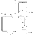
- FIG. 5 is a plan view, a front view, and a right side view showing the configuration of the stopper member 11 of FIG. 6 is a plan view, a left side view, and a front view showing the configuration of the stopper member 12 of FIG.
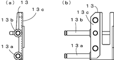
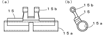
- FIG. 7 is a left side view and a front view showing the configuration of the link connecting member 13 of FIG. 8 is a front view and a right side view showing the configuration of the link drive member 15 of FIG.
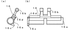
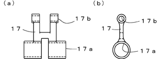
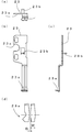
- FIG. 9 is a front view and a right side view showing the configuration of the link drive member 1 of FIG. 10 is a front view and a right side view showing the configuration of the link driven member 17 of FIG. 11 is a plan view, a front view, a right side view, and an enlarged view of the vicinity of the tip, showing the configuration of the hook member 23 of FIG. 12 is a plan view, a front view, and a right side view showing the configuration of the pressing member 25 of FIG.
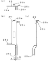
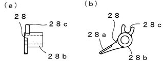
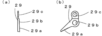
- FIG. 13 is a front view and a right side view showing the configuration of the movable blade member 28 of FIG. 14 is a front view and a right side view showing the configuration of the fixed blade member 29 of FIG. 15 is a front view and a right side view showing the configuration of the switching lever 21 of FIG.
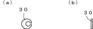
- FIG. 16 is a front view and a right side view showing the configuration of the eccentric collar 30 of FIGS. 2 and 3.
- FIG. 17 is a simplified front view and right side view showing a state in which the end yarn processing apparatus 1 of FIG. 1 is waiting at the reference position.
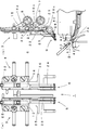
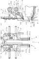
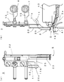
- FIG. 18 is a simplified front view and right side view showing a state in which the end yarn processing apparatus 1 of FIG. 1 starts an operation for gripping a knitting yarn and starts to open the cutter 9.
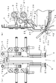
- FIG. 19 is a simplified front view and a right side view showing a state in which the end yarn processing apparatus 1 of FIG.
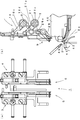
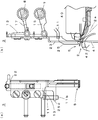
- FIG. 20 is a simplified front view showing a state in which the cutter 9 starts to close in the middle of ascending after the end yarn processing apparatus 1 of FIG. 1 moves the gripping portions 5 and 6 into the tooth opening 2 and grips the knitting yarn.
- FIG. 21 is a simplified front view and right side view showing a state in which the left gripper unit 3 of FIG. 1 is starting to open the hook 23a and the thread retainer 25a in the middle of the single operation of allowing the gripping portion 5 to enter the tooth mouth 2.
- FIG. FIG. 22 shows a state in which the hook 23a and the thread presser 25a are opened and the hook 23a enters the tooth opening 2 in the middle of the single operation in which the left gripper unit 3 in FIG. It is the simplified front view and right view which show these.
- FIG. 1 shows a simplified schematic configuration of an end yarn processing apparatus 1 as an embodiment of the present invention.
- the knitted fabric is knitted by supplying knitting yarn from a yarn supplying member such as a yarn feeder to the knitting needles that advance to the tooth opening 2 facing the front and back needle beds.
- a yarn supplying member such as a yarn feeder
- a large number of knitting needles are arranged on the needle bed, and the knitting needle is selectively driven while the carriage reciprocates along the needle bed, and the knitted fabric is knitted while entraining the yarn supplying member.
- the yarn supplying member travels along a yarn path that is installed above the mouthpiece 2.
- the knitting yarn passes from the knitting needle at the end of knitting to the yarn supplying member immediately before the knitting of the finger bag portion of the glove is once finished and the knitting of the next finger bag portion is started.
- the end yarn processing apparatus 1 is provided to catch the knitting yarn in such a state, cut it, and process the resulting end yarn.
- the end yarn processing apparatus 1 includes two gripper units, a left gripper unit 3 and a right gripper unit 4.
- the left gripper unit 3 and the right gripper unit 4 have gripping portions 5 and 6 as grippers capable of gripping the knitting yarn at their tips, respectively.
- the left gripper unit 3 and the right gripper unit 4 are supported by two drive shafts 7 and 8 installed above the tooth mouth 2 so as to be slidable in the left-right direction.
- the operations of the grips 5 and 6 are driven by the rotation of the drive shafts 7 and 8, respectively.
- the left gripper unit 3 and the right gripper unit 4 have basically the same operation and configuration at least with respect to the grip portions 5 and 6.
- the left gripper unit 3 is also provided with a knurled cutter 9. Although the operation of the grip portion 5 of the left gripper unit 3 is performed by the rotation of the drive shaft 7, the opening / closing drive of the cutter 9 is performed by the rotation of the drive shaft 8 that drives the operation of the grip portion 6 of the right gripper unit 4. Done.
- the left gripper unit 3 and the right gripper unit 4 support each component with a base member 10.
- the base member 10 is common to the left and right, the left gripper unit 3 forms a grip portion 5 on the right side of the base member 10, and the right gripper unit 4 forms a grip portion 6 on the left side of the base member 10.
- a left stopper member 11 and a right stopper member 12 are attached to the base members 10 of the left gripper unit 3 and the right gripper unit 4, respectively.
- the gripping parts 5 and 6 are driven via four-side link mechanisms that respond to the rotation of the drive shafts 7 and 8, respectively.
- One side of the four-side link mechanism is formed between the drive shafts 7 and 8, and this side is fixed. Sides facing this side are formed by link connecting members 13 and 14, respectively.
- the link connecting member 13 on the left gripper unit 3 side extends a drive connecting shaft 13a and a driven connecting shaft 13b to the left.
- a link drive member 15 is provided between the drive connecting shaft 13 a and the drive shaft 7.
- the link connecting member 14 on the right gripper unit 4 side extends a drive connecting shaft 14a and a driven connecting shaft 14b to the right.
- a link drive member 16 is provided between the drive connecting shaft 14 a and the drive shaft 8.
- a link driven member 17 is provided between the driven connecting shafts 13b and 14b of the link connecting members 13 and 14 and the drive shafts 8 and 7, respectively.
- the movement of the left gripper unit 3 and the right gripper unit 4 in the direction along the drive shafts 7, 8 is a lateral pulling force transmitted from the movable rack 19 via the moving member 18 to the upper part of the base member 10 or This is done with extrusion force.
- a track member 20 that houses the movable rack 19 is provided behind the base member 10.
- the track member 20 is installed above the tooth mouth 2 in parallel with the drive shafts 7 and 8.
- the movable rack 19 is made of a synthetic resin, is flexible, and has rack teeth that mesh with teeth provided on the moving member 18.
- the movable rack 19 extends from both the left and right sides of the track member 20, and the moving member 18 is attached to the tip.
- the left and right movable racks 19 are independently pushed into the receiving grooves in the track member 20 and pulled back from the lateral end portions (not shown).
- the left gripper unit 3 and the right gripper unit 4 can move independently from side to side as long as they do not collide with each other.
- the left and right movable racks 19 each have a length corresponding to at least the width of the needle bed so that the left gripper unit 3 and the right gripper unit 4 can reciprocate within a range in which the needle bed is provided. If the position of the left gripper unit 3 or the right gripper unit 4 is in any position from the end of the needle bed on the driving side to the end on the opposite side, the end of the movable rack 19 on the driving side It protrudes from the drive-side end of the member 20. The movable rack 19 protruding from the end of the track member 20 is guided so as to be bent in the thickness direction.
- the drive shafts 7 and 8 can be used as a track without providing the track member 20. If a track such as the track member 20 is provided, the sliding resistance to the drive shafts 7 and 8 during movement can be reduced, and the load on the drive shafts 7 and 8 can be reduced.
- FIG. 2 and 3 show the configurations of the left gripper unit 3 and the right gripper unit 4, respectively.
- 2A is a plan view
- FIG. 2B is a front view
- FIG. 2C is a right side view
- FIG. 3A is a plan view
- FIG. 3B is a left side view
- FIG. 3C is a front view.
- the structure seen from each is shown.
- FIG. 2 and FIG. 3 and each of the following figures for reasons such as avoiding complications, it is a figure seen from a different direction, and the part described in the figure seen from the other direction is omitted, Conversely, the omitted parts are described in other directions.
- the left gripper unit 3 is provided with a switching lever 21 as a switching member that switches the cutter 9 to open and close.
- the switching lever 21 is rocked and displaced at the upper end by a contact protrusion provided at the left end of the link driving member 16 on the right gripper unit 4 side, and switches the opening and closing of the cutter 8 at the lower end.
- the grip portions 5 and 6 of the left gripper unit 3 and the right gripper unit 4 are formed by hook members 23 and 24 and presser members 25 and 26 that are connected via a tension spring 22, respectively.
- the tension spring 22 urges the upper ends of the pressing members 25 and 26 downward by the hook members 23 and 24.
- the cutter 9 includes a movable blade member 28 and a fixed blade member 29 that are pressed by the compression spring 27.
- the movable blade member 28 is driven by the switching member 21 to open and close.
- the hook members 23 and 24 are screwed to the link connecting members 13 and 14 at two locations, upper and lower, respectively.
- An eccentric collar 30 is screwed in the middle between the upper and lower screw locations.
- FIG. 4 shows the configuration of the base member 10.
- 4A is a plan view
- FIG. 4B is a front view
- FIG. 4C is a view seen from the right side.
- the base member 10 is provided with a left gripper accommodating portion 10a on the right side and a right gripper accommodating portion 10b on the left side, which can be shared by the left gripper unit 3 and the right gripper unit 4, and either one can be incorporated.
- the link driving members 15 and 16 and the link driven member 17 are assembled so as to cover both the left gripper accommodating portion 10a and the right gripper accommodating portion 10b.
- the center of the base member 10 protrudes forward to form a wall in the left-right direction, and is provided with drive shaft insertion holes 10d and 10e through which the drive shafts 7 and 8 are inserted. Behind the base member 10 is provided a track fitting portion 10f that fits the track member 20 shown in FIGS.
- 5 and 6 show the structures of the stopper members 11 and 12 of the left gripper unit 3 and the right gripper unit 4, respectively.
- 5 (a) is a plan view
- FIG. 5 (b) is a front view
- FIG. 5 (c) is a right side view
- FIG. 6 (a) is a plan view
- FIG. 6 (b) is a left side view
- FIG. The structure seen from each is shown.
- the stopper members 11 and 12 are provided with upper stoppers 11a and 12a and lower stoppers 11b and 12b, respectively.
- the stopper member 11 attached to the left gripper unit 3 is also provided with a cutter attaching portion 11c.
- FIG. 7 shows the structure of the link connecting member 13 provided in the left gripper unit 3.
- FIG. 7A shows the configuration viewed from the left side
- FIG. 7B shows the configuration viewed from the front.
- the link connecting member 14 provided in the right gripper unit 4 is basically symmetrical with the link connecting member 13.
- the lower side is the drive connecting shaft 13a and the upper side is the driven connecting shaft 13b
- the driving connecting shaft 14a is the upper side
- the driven connecting shaft 14b is the lower side.
- a joint 13c is provided, and the hook member 23 and the eccentric collar 30 are screwed. The same applies to the link connecting member 14.
- FIG. 8 (a) is the front
- FIG. 8 (b) is the right side
- FIG. 9 (a) is the left side
- FIG. 9 (b) is the front
- FIG. 10 (a) is the front
- FIG. 10 (b) is the right.
- the structure seen from the surface is shown respectively.
- the drive shaft insertion holes 15a, 16a,... Through which the drive shafts 7, 8 are inserted into the link drive members 15, 16 and the link driven member 17.
- 17a and connecting shaft insertion holes 15b, 16b, and 17b through which the drive connecting shafts 13a and 14a and the driven connecting shafts 13b and 14b of the link connecting members 13 and 14 are inserted, respectively.
- the drive shaft insertion holes 15a and 16a of the link drive members 15 and 16 have the drive shafts 7 and 16a. It is possible to prevent rotation by utilizing the flat cutout portion of 8.
- the link driving member 16 used in the right gripper unit 4 shown in FIG. 9 has two contact protrusions 16c and 16d at the left end facing the left gripper unit 3 side.
- the link drive member 16 rotates the drive shaft 8 that opens and closes the grip 6 of the right gripper unit 4 to rotate the left gripper 16. It functions as a drive member that opens and closes the cutter 9 of the unit 3.
- 11 and 12 show configurations of the hook member 23 and the pressing member 25 that form the grip portion 5 of the left gripper unit 3, respectively.
- 11 (a) and 12 (a) are plan views
- FIG. 11 (b) and FIG. 12 (b) are front views
- FIG. 11 (c) and FIG. 12 (c) are configurations viewed from the right side.
- a hook 23a is formed at the lower end of the hook member 23, a spring hook 23b is formed in the middle of the upper side, and a joint 23c is formed on the left side.
- the hook 23a is formed by bending a metal plate having a shape as shown in FIG.
- the width W is, for example, 2.6 mm, and the gap D is 0.6 mm.
- a portion having a thickness T shown in FIG. This portion of thickness T is divided into two, and the interval is S.
- a portion having a width W of the hook 23a is inserted into the interval S.
- the thickness T is 0.8 mm, and the distance S between the thread clamps 25a is 2.4 mm. Therefore, when the thread retainer 25a enters the hook 23a, the narrow portion is elastically spread out, so that the hook 23a and the thread retainer 25a are held together.
- the knitting yarn is held between the upper surface of the hook 23a and the lower end of the yarn presser 25a.
- a spring hook 25 b is provided at the upper end of the pressing member 25.
- a tension spring 22 shown in FIG. 2 is stretched between the spring hooks 23 b and 25 b of the hook member 23 and the pressing member 25.
- the pressing member 25 is also provided with an upper protrusion 25c and a lower protrusion 25d, respectively, for contacting the upper stopper 11a and the lower stopper 11b of the stopper member 11 shown in FIG.
- the hook member 24 and the presser member 26 that form the grip portion 6 of the right gripper unit 4 are basically symmetrical with the hook member 23 and the presser member 25 shown in FIGS. However, in the presser member 26, only the upper protrusion corresponding to the upper protrusion 25c of the presser member 25 is provided at a position shifted downward from the symmetrical position.
- the upper stopper 11a provided on the stopper member 11 of the left gripper unit 3 and the upper stopper 12a provided on the stopper member 12 of the right gripper unit 4 protrude in directions approaching each other. This is because the position of the corresponding upper protrusion is also shifted.
- FIGS. 13, 14, 15 and 16 show the configurations of the movable blade member 28, the fixed blade member 29, the switching lever 21 and the eccentric collar 30, respectively.
- (A) of each figure shows the structure seen from the front, (b) from the right side, respectively.
- the movable blade member 28 and the fixed blade member 29 are opened and closed by swinging displacement with the intermediate bosses 28b and 29b as fulcrums.
- a driving recess 28 c is provided at the upper end of the movable blade member 29.
- the upper end of the fixed blade member 29 is provided with a fixed fixing hole 29c that is fixed by screwing.
- FIGS. 17 to 20 show a one-step process in which the left gripper unit 3 and the right gripper unit 4 are brought close to each other as shown in FIG. 1, and the drive shafts 7 and 8 are angularly displaced in one direction and then angularly displaced in the other.
- an outline of the operation for cutting from capturing the knitting yarn will be shown.
- (a) is a front view
- (b) is a configuration viewed from the right side of the left gripper unit 3.
- the two contact protrusions 16c and 16d of the link driving member 16 are provided on the right gripper unit 4, they are shown simultaneously with the left gripper unit 3 side because they drive the opening and closing of the cutter 9.
- the rear side is shown in a simplified manner among the needle beds 40 facing each other with the tooth mouth 2 interposed therebetween, an equivalent needle bed is provided on the front side, and knitting needles 41 are arranged in parallel.
- a movable sinker 42 and the like are also provided between the knitting needles 41.
- the knitting needle 41 and the movable sinker 42 advance and retreat to and from the tooth mouth 2, and the knitted fabric is knitted by receiving the supply of the knitting yarn from the yarn feeder 43 provided at the lower end of the yarn feeding member such as a yarn feeder. Since the needle bed 40 is inclined so as to be higher when approaching the tooth opening 2 and lower when separated from the tooth opening 2, the center line 2 a in the vertical direction of the tooth opening 2 is the needle bed 40 on the paper surface.
- the grips 5 and 6 When shown in a horizontal state, it is inclined on the paper surface. Since the yarn path rail on which the yarn feeding member such as a yarn feeder moves is installed above the tooth mouth 2, the position where the left gripper unit 3 and the right gripper unit 4 are arranged is directly above the tooth mouth 2. It has shifted to the back needle bed 40 side. Since the grips 5 and 6 are moved by the four-side link mechanism, the grips 5 and 6 can enter the tooth mouth 2 even from a position slightly shifted laterally.
- FIG. 17 shows a reference state in which the gripping portions 5 and 6 are waiting above the tooth mouth 2.
- the grips 5 and 6 and the cutter 9 are both closed.
- the drive shafts 7 and 8 are angularly displaced counterclockwise in the drawing, the link drive members 15 and 16 are driven, the link driven member 17 is driven, and the link connecting members 13 and 14 start to descend. Since the hook members 23 and 24 are joined to the link connecting members 13 and 14, respectively, the hook members 23 and 24 are also lowered.
- the holding members 25 and 26 are also pulled by the hook members 23 and 24 via the tension spring 22 and lowered.
- FIG. 18 shows a state in which the upper protrusions 25c and 26c of the pressing members 25 and 26 are in contact with the upper stoppers 12a and 11a of the stopper members 12 and 11, respectively, and the lowering of the pressing members 25 and 26 is stopped. If the drive shafts 7 and 8 continue to be angularly displaced in the counterclockwise direction, only the hook members 23 and 24 are lowered, and the gripping portions 5 and 6 are opened. As shown in the figure, when one of the contact protrusions 16c of the link driving member 16 contacts the contact portion 21a of the switching lever 21, the driving recess 28c of the movable blade member 28 with which the action portion 21c of the switching lever 21 engages. Then, the movable blade member 28 starts to open.
- FIG. 19 shows a state in which the hooks 23a and 24a of the gripping portions 5 and 6 in the opened state are advanced into the tooth opening 2.
- the movable blade member 28 is fully opened.
- FIG. 20 shows a state in which the drive shafts 7 and 8 are angularly displaced clockwise and returned to the reference state.
- the hook members 23 and 24 are raised, the grip portions 5 and 6 are closed, and the knitting yarn can be gripped.
- the pressing members 25 and 26 reach a position where they are stopped, the pressing members 25 and 26 are also lifted together with the hook members 23 and 24.
- the other abutment protrusion 16d of the link drive member 16 abuts on the abutment portion 21a of the switching lever 21, it is movable via the drive recess 28c of the movable blade member 28 with which the action portion 21c of the switching lever 21 engages.
- the blade member 28 begins to close.
- the cutter 9 should be opened and closed at appropriate timings. Can do.
- FIG. 21 and FIG. 22 show the operation of the gripper 5 with the left gripper unit 3 alone.
- (a) is a front view
- (b) is a configuration viewed from the right side of the left gripper unit 3.
- the pressing member 25 moves down following the hook member 23 until the lower protrusion 25 d of the pressing member 25 contacts the lower stopper 11 b of the stopper member 11. If the hook member 23 is further lowered, the hook 23a can be advanced into the tooth opening 2 in a state where the grip portion 5 is slightly opened and the gripping force of the knitting yarn is weakened.
- Such a single operation can be used for processing an end yarn generated by cutting a knitting yarn, as described in FIG.
- a similar single operation can be performed in the right gripper unit 4 as well.
- the cutter 9 cannot be opened and closed to cut the knitting yarn unless the left gripper unit 3 and the right gripper unit 4 are brought close to each other as shown in FIG. There is no risk of cutting the knitting yarn due to malfunction during operation.
- the link driving member 15 provided in the left gripper unit 3 is provided with the contact protrusions 16c and 16d for driving the cutter, the gripping on the left gripper unit 3 side by the rotation of the driving shaft 7 is performed.
- the part 5 and the cutter 9 can be operated simultaneously. In this case, the knitting yarn extending from the knitted fabric to the yarn supplying member side can be cut and gripped in the same manner as the knitting yarn gripping and cutting device disclosed in Patent Document 2.
Landscapes
- Engineering & Computer Science (AREA)
- Textile Engineering (AREA)
- Knitting Machines (AREA)
- Braiding, Manufacturing Of Bobbin-Net Or Lace, And Manufacturing Of Nets By Knotting (AREA)
Abstract
L'invention porte sur un dispositif de traitement d'extrémité de fil pour une machine à tricoter rectiligne. Selon l'invention, des fils à tricoter peuvent être saisis et coupés par actionnement de deux dispositifs de saisie et d'un dispositif de coupe en un pas de rotation d'un arbre d'entraînement. Une unité de saisie gauche (3) et une unité de saisie droite (4) sont équipées, à leurs extrémités distales respectives, de parties de saisie (5 et 6) capables de saisir des fils à tricoter. L'unité de saisie gauche (3) et l'unité de saisie droite (4) peuvent coulisser et se déplacer longitudinalement par rapport à deux arbres d'entraînement (7 et 8) érigés au-dessus d'une embouchure à dents (2). Les actions des parties de saisie (5 et 6) sont actionnées, respectivement, par les rotations des arbres d'entraînement (7 et 8). L'unité de saisie gauche (3) est en outre équipée d'un dispositif de coupe en forme de ciseaux (9). L'actionnement d'ouverture/de fermeture du dispositif de coupe (9) est effectué par la rotation de l'arbre d'entraînement (8) pour commander l'action de la partie de saisie (6) de l'unité de saisie droite (4). Les actions de saisie et de coupe des fils à tricoter par les deux parties de saisie (5 et 6) peuvent être effectuées par les rotations d'un pas des arbres d'entraînement (7 et 8).
Priority Applications (3)
| Application Number | Priority Date | Filing Date | Title |
|---|---|---|---|
| EP08868426.1A EP2241660B1 (fr) | 2007-12-29 | 2008-12-25 | Dispositif de traitement d'extrémité de fil pour machine à tricoter rectiligne |
| CN200880122863.9A CN101910489B (zh) | 2007-12-29 | 2008-12-25 | 横编机的纱头处理装置 |
| JP2009547892A JP5161242B2 (ja) | 2007-12-29 | 2008-12-25 | 横編機の端糸処理装置 |
Applications Claiming Priority (2)
| Application Number | Priority Date | Filing Date | Title |
|---|---|---|---|
| JP2007-341539 | 2007-12-29 | ||
| JP2007341539 | 2007-12-29 |
Publications (1)
| Publication Number | Publication Date |
|---|---|
| WO2009084193A1 true WO2009084193A1 (fr) | 2009-07-09 |
Family
ID=40823929
Family Applications (1)
| Application Number | Title | Priority Date | Filing Date |
|---|---|---|---|
| PCT/JP2008/003945 Ceased WO2009084193A1 (fr) | 2007-12-29 | 2008-12-25 | Dispositif de traitement d'extrémité de fil pour machine à tricoter rectiligne |
Country Status (4)
| Country | Link |
|---|---|
| EP (1) | EP2241660B1 (fr) |
| JP (1) | JP5161242B2 (fr) |
| CN (1) | CN101910489B (fr) |
| WO (1) | WO2009084193A1 (fr) |
Cited By (2)
| Publication number | Priority date | Publication date | Assignee | Title |
|---|---|---|---|---|
| JP2014221958A (ja) * | 2013-05-14 | 2014-11-27 | 株式会社島精機製作所 | 横編機の端糸処理装置 |
| EP4768651A1 (fr) | 2024-12-27 | 2026-07-01 | Shima Seiki Mfg., Ltd. | Procédé de tricotage, programme informatique de tricotage et dispositif d'enregistration du programme |
Families Citing this family (1)
| Publication number | Priority date | Publication date | Assignee | Title |
|---|---|---|---|---|
| JP7785637B2 (ja) * | 2022-08-31 | 2025-12-15 | 株式会社島精機製作所 | 端糸処理装置及び端糸処理方法 |
Citations (4)
| Publication number | Priority date | Publication date | Assignee | Title |
|---|---|---|---|---|
| JPH08325901A (ja) | 1995-05-24 | 1996-12-10 | Shima Seiki Mfg Ltd | 横編機における編糸切断把持装置 |
| JP2005089933A (ja) | 2003-09-19 | 2005-04-07 | Shima Seiki Mfg Ltd | 横編機の端糸処理装置および方法 |
| JP2007002361A (ja) * | 2005-06-23 | 2007-01-11 | Gunze Ltd | 編み機を用いた編成方法及び丸編み機を用いた編成方法及び横編機を用いた編成方法及び丸編み機及びストライパー装置 |
| WO2008081579A1 (fr) * | 2006-12-29 | 2008-07-10 | Shima Seiki Mfg., Ltd. | Dispositif de traitement d'extrémité de fil sur une machine à tricoter plate |
Family Cites Families (4)
| Publication number | Priority date | Publication date | Assignee | Title |
|---|---|---|---|---|
| JPS61181047A (ja) | 1985-02-05 | 1986-08-13 | Toshiba Corp | アノ−ドボタンの内セルとその製造方法 |
| CN2274198Y (zh) * | 1996-10-26 | 1998-02-11 | 张民 | 台车断纱保护器的切刀装置 |
| DE19844833A1 (de) * | 1998-09-30 | 2000-04-13 | Stoll & Co H | Fadenklemm- und Schneidvorrichtung für Strickmaschinen |
| CN2799607Y (zh) * | 2005-04-30 | 2006-07-26 | 富胜精密机械(绍兴)有限公司 | 织袜机切纱用剪刀装置 |
-
2008
- 2008-12-25 CN CN200880122863.9A patent/CN101910489B/zh not_active Expired - Fee Related
- 2008-12-25 EP EP08868426.1A patent/EP2241660B1/fr not_active Not-in-force
- 2008-12-25 JP JP2009547892A patent/JP5161242B2/ja not_active Expired - Fee Related
- 2008-12-25 WO PCT/JP2008/003945 patent/WO2009084193A1/fr not_active Ceased
Patent Citations (5)
| Publication number | Priority date | Publication date | Assignee | Title |
|---|---|---|---|---|
| JPH08325901A (ja) | 1995-05-24 | 1996-12-10 | Shima Seiki Mfg Ltd | 横編機における編糸切断把持装置 |
| JP2005089933A (ja) | 2003-09-19 | 2005-04-07 | Shima Seiki Mfg Ltd | 横編機の端糸処理装置および方法 |
| JP4015980B2 (ja) * | 2003-09-19 | 2007-11-28 | 株式会社島精機製作所 | 横編機の端糸処理装置および方法 |
| JP2007002361A (ja) * | 2005-06-23 | 2007-01-11 | Gunze Ltd | 編み機を用いた編成方法及び丸編み機を用いた編成方法及び横編機を用いた編成方法及び丸編み機及びストライパー装置 |
| WO2008081579A1 (fr) * | 2006-12-29 | 2008-07-10 | Shima Seiki Mfg., Ltd. | Dispositif de traitement d'extrémité de fil sur une machine à tricoter plate |
Non-Patent Citations (1)
| Title |
|---|
| See also references of EP2241660A4 * |
Cited By (2)
| Publication number | Priority date | Publication date | Assignee | Title |
|---|---|---|---|---|
| JP2014221958A (ja) * | 2013-05-14 | 2014-11-27 | 株式会社島精機製作所 | 横編機の端糸処理装置 |
| EP4768651A1 (fr) | 2024-12-27 | 2026-07-01 | Shima Seiki Mfg., Ltd. | Procédé de tricotage, programme informatique de tricotage et dispositif d'enregistration du programme |
Also Published As
| Publication number | Publication date |
|---|---|
| CN101910489A (zh) | 2010-12-08 |
| JP5161242B2 (ja) | 2013-03-13 |
| EP2241660A4 (fr) | 2013-02-20 |
| EP2241660B1 (fr) | 2014-01-01 |
| CN101910489B (zh) | 2012-02-08 |
| JPWO2009084193A1 (ja) | 2011-05-12 |
| EP2241660A1 (fr) | 2010-10-20 |
Similar Documents
| Publication | Publication Date | Title |
|---|---|---|
| JP4164157B2 (ja) | 糸切り装置を備えたミシン | |
| WO2005028726A1 (fr) | Dispositif et procede destines a traiter un fil d'extremite d'une machine de tricotage trame | |
| KR101378147B1 (ko) | 단사 삽입장치 | |
| CN210314701U (zh) | 横编机的编织纱保持切断装置 | |
| JP2009219780A (ja) | 二本針ミシン | |
| JP2016144492A (ja) | ミシン | |
| KR101329122B1 (ko) | 단사 삽입장치 | |
| JP5161242B2 (ja) | 横編機の端糸処理装置 | |
| JP5757830B2 (ja) | 複合針を備える横編機、および横編機のスライダー制御方法 | |
| KR100457453B1 (ko) | 횡편기의 말단 편사 삽입장치 | |
| US8028634B2 (en) | Threading device of sewing machine | |
| KR100983691B1 (ko) | 재봉틀 | |
| WO2015033996A1 (fr) | Machine à coudre | |
| JP5252894B2 (ja) | 自動横編機 | |
| KR101652025B1 (ko) | 재봉기의 윗실유지장치 | |
| JP2009240599A (ja) | ミシンの上糸つかみ装置 | |
| US8844454B2 (en) | Activation device for a path and time dependent motion of a thread cutting and lead-in stitching unit | |
| JP4163085B2 (ja) | 移動体連行状態切換え可能な横編機 | |
| JP6374745B2 (ja) | ミシン | |
| TWI589745B (zh) | 機械編織針頭、用於縫合形成的設置、及使用該設置於編織機中 | |
| JP4377282B2 (ja) | 畳用縫着装置 | |
| JPH0551262U (ja) | ミシンの自動糸切り装置 |
Legal Events
| Date | Code | Title | Description |
|---|---|---|---|
| WWE | Wipo information: entry into national phase |
Ref document number: 200880122863.9 Country of ref document: CN |
|
| 121 | Ep: the epo has been informed by wipo that ep was designated in this application |
Ref document number: 08868426 Country of ref document: EP Kind code of ref document: A1 |
|
| WWE | Wipo information: entry into national phase |
Ref document number: 2009547892 Country of ref document: JP |
|
| NENP | Non-entry into the national phase |
Ref country code: DE |
|
| WWE | Wipo information: entry into national phase |
Ref document number: 2008868426 Country of ref document: EP |