WO2009084344A1 - Moteur pas à pas et instrument l'utilisant - Google Patents
Moteur pas à pas et instrument l'utilisant Download PDFInfo
- Publication number
- WO2009084344A1 WO2009084344A1 PCT/JP2008/071272 JP2008071272W WO2009084344A1 WO 2009084344 A1 WO2009084344 A1 WO 2009084344A1 JP 2008071272 W JP2008071272 W JP 2008071272W WO 2009084344 A1 WO2009084344 A1 WO 2009084344A1
- Authority
- WO
- WIPO (PCT)
- Prior art keywords
- gear
- rotor magnet
- stepping motor
- rotating
- output
- Prior art date
- Legal status (The legal status is an assumption and is not a legal conclusion. Google has not performed a legal analysis and makes no representation as to the accuracy of the status listed.)
- Ceased
Links
Images



Classifications
-
- G—PHYSICS
- G01—MEASURING; TESTING
- G01R—MEASURING ELECTRIC VARIABLES; MEASURING MAGNETIC VARIABLES
- G01R7/00—Instruments capable of converting two or more currents or voltages into a single mechanical displacement
- G01R7/04—Instruments capable of converting two or more currents or voltages into a single mechanical displacement for forming a quotient
- G01R7/06—Instruments capable of converting two or more currents or voltages into a single mechanical displacement for forming a quotient moving-iron type
-
- G—PHYSICS
- G01—MEASURING; TESTING
- G01D—MEASURING NOT SPECIALLY ADAPTED FOR A SPECIFIC VARIABLE; ARRANGEMENTS FOR MEASURING TWO OR MORE VARIABLES NOT COVERED IN A SINGLE OTHER SUBCLASS; TARIFF METERING APPARATUS; MEASURING OR TESTING NOT OTHERWISE PROVIDED FOR
- G01D2213/00—Indexing scheme relating to constructional details of indicators
- G01D2213/10—Drivers for gauges
Definitions
- the present invention relates to a stepping motor and an instrument device using the stepping motor, and more particularly to a stepping motor capable of reliably retaining an output shaft at a predetermined position and an instrument device using the stepping motor.
- Some conventional stepping motors are provided with a fixed magnet around the rotor magnet in order to keep the rotor magnet in a predetermined position (see, for example, Patent Document 1). Japanese Patent Laid-Open No. 2001-41981
- the present invention pays attention to the above-mentioned problems, and a stepping motor that can reliably keep the output shaft in a predetermined position and can keep the product cost low, and an instrument device using the stepping motor
- the purpose is to provide.
- the present invention includes a multi-pole magnetized rotor magnet, a rotor gear provided coaxially with the rotor magnet and rotating as the rotor magnet rotates, a first gear meshing with the rotor gear, and the first gear.
- An intermediate gear having a second gear provided coaxially with the other gear, an output gear meshing with the second gear of the intermediate gear, and a drive arranged around the rotor magnet and output from the control means
- An excitation coil that generates a rotating magnetic field by inputting a waveform and applies a rotational force to the rotor magnet, a first rotating shaft that serves as a rotation center of the rotor magnet, and a second that serves as a rotation center of the intermediate gear.
- the second rotation shaft or the output shaft is made of a magnetic member, and the rotating magnetic field is generated in the excitation coil.
- the present invention also includes a rotor magnet magnetized with multiple poles, a rotor gear provided coaxially with the rotor magnet and rotating as the rotor magnet rotates, a first gear meshing with the rotor gear, An intermediate gear having a second gear provided coaxially with the first gear, an output gear meshing with the second gear of the intermediate gear, and an output gear arranged around the rotor magnet and output from the control means.
- An excitation coil that generates a rotating magnetic field by inputting a driving waveform, a first rotating shaft that becomes a rotation center of the rotor magnet, and a rotation center of the intermediate gear
- An instrument device using a stepping motor having a second rotation shaft and an output shaft serving as a rotation center of the output gear, the pointer being attached to the output shaft, and disposed behind the pointer Display
- a stopper means for holding the pointer at a predetermined position of the display plate, the second rotating shaft or the output shaft is made of a magnetic member, and when the rotating magnetic field is not generated in the exciting coil, By pulling with the rotor magnet, the pointer is held at the predetermined position determined by the stopper means.
- the present invention is provided with a case member that accommodates at least the output shaft, and the stopper means includes a first protrusion provided on the output gear and a second protrusion provided on the case member. It is what is done.
- the stopper means comprises a protrusion provided on the display plate.
- the magnetic pole peak position of the rotor magnet that is attracted to the second rotating shaft or the output shaft is the first rotating shaft and the first rotating shaft when the pointer is in contact with the predetermined position.
- the number of magnetic poles of the rotor magnet is n (n is an integer) in a direction away from the predetermined position with respect to a straight line connecting the two rotation axes or the output shaft, the value is within (360 / 2n) degrees. Is provided at an angle of.
- a stepping motor and its stepping motor that can achieve the intended purpose, can reliably keep the output shaft in a predetermined position, and can reduce the product cost.
- the instrument device used can be provided.
- the output shaft can be reliably held at a predetermined position, and the product cost can be kept low.
- a motor can be provided.
- the output shaft can be securely held at a predetermined position, and the product cost can be kept low.
- An instrument device using a motor can be provided.
- the stopper means can physically hold the pointer at a predetermined position, and it is possible to prevent the pointer from coming into contact with the stopper means and jumping up.
- the stopper means is configured inside the stepping motor, there is no need to provide a projection on the display board of the instrument device, the display board can be made a simple design, and a dedicated projection must be provided. Product costs can be kept low because there is no such thing.
- the stopper means can physically hold the pointer at a predetermined position, and the pointer can be prevented from jumping up against the stopper means. Further, since the stopper means is provided on the display board, the accuracy of the predetermined position determined by the stopper means can be easily improved.
- the pointer since the rotational force is applied in the direction in which the pointer is further rotated in the direction of the predetermined position while the pointer is held at the predetermined position by the stopper means, the pointer is surely predetermined. Can be kept in the position.
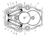
- the top view of the stepping motor of one embodiment of the present invention Sectional drawing of the AA line in FIG.
- the top view of the stepping motor which removed the upper case of the embodiment.
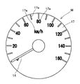
- the front view of the instrument apparatus using the stepping motor of the embodiment Explanatory drawing of the embodiment.
- the stepping motor 1 used in the meter device M of the present embodiment includes a rotor magnet 2 magnetized with multiple poles, a rotor gear 3 fixed to the rotor magnet 2, a first gear 4a meshing with the rotor gear 3, and this An intermediate gear 4 having a first gear 4a and a second gear 4b provided on the same axis, an output gear 5 meshing with the second gear 4b of the intermediate gear 4, a rotating magnetic field and generating a rotor magnet 2
- Two exciting coils 9 for applying a rotational force to the metal a first rotating shaft 10 made of metal serving as the rotation center of the rotor magnet 2, a second rotating shaft 11 made of metal serving as the rotation center of the intermediate gear 4,
- the rotor magnet 2 is made of a synthetic resin having magnetism called a so-called plastic magnet, and has a circular shape and a donut shape with a through hole in the center.
- the rotor gear 3 and the first rotating shaft 10 pass through this through hole.
- the rotor magnet 2 includes a large number of magnetic poles so as to be uniform in the radial direction around the rotation axis. In this embodiment, two N poles and two S poles are provided for a total of four magnetic poles. Therefore, when the rotation is performed with the first rotation shaft 10 as the central axis, the outer circumferential surface of the rotor magnet 2 is multipolarly magnetized along the rotation direction.
- the rotor gear 3 is made of synthetic resin not having magnetism, and rotates with the rotation of the rotor magnet 2 as described above. Further, the first rotating shaft 10 passes through the rotor gear 3.
- the intermediate gear 4 is made of a synthetic resin not having magnetism, and integrally includes a first gear 4a and a second gear 4b.
- the first gear 4 a meshes with the rotor gear 3.
- the second gear 4 b meshes with the output gear 5.
- the first gear 4a and the second gear 4b are provided coaxially.
- the intermediate gear 4 is provided with a second rotation shaft 11 serving as a rotation center.
- the 2nd rotating shaft 11 consists of a magnetic member, and attracts the rotor magnet 2 with magnetic force.
- the output gear 5 is also made of a synthetic resin not having magnetism, and meshes with the second gear 4b of the intermediate gear 4.
- the output gear 5 is provided with an output shaft 6 serving as a rotation center.
- a first protrusion 15 a constituting the stopper means 15 is integrally provided on the lower surface of the output gear 5.
- the first protrusion 15a abuts on a second protrusion 15b provided on the case member 12, which will be described later, and stops the rotation of the output gear 5 at a predetermined position.
- the intermediate gear 4 and the output gear 5 transmit the rotation of the rotor magnet 2 while decelerating it.
- the exciting coil 9 is formed by winding a conductive metal wire such as copper around a bobbin 9a made of synthetic resin.
- the exciting coil 9 is connected to control means via a terminal 9b provided on the bobbin 9a.
- the bobbin 9a is a cylinder provided with a through hole having a rectangular cross-sectional shape. And the exciting coil 9 is arrange
- the inner peripheral surfaces of are facing each other.
- the two excitation coils 9 are respectively input with drive waveforms output from control means (not shown), so that a rotating magnetic field is generated in the rotor magnet 2 and a rotational force is applied to the rotor magnet 2. .
- the case member 12 is made of a synthetic resin not having magnetism and is divided into upper and lower parts.
- the case member 12 divided in the vertical direction is fixed by hooking a locking claw 12a provided on each case member 12.
- the case member 12 is integrally provided with a second projecting portion 15 b that abuts on the first projecting portion 15 a provided on the output gear 5.
- the case member 12 supports the first rotating shaft 10, the second rotating shaft 11, and the output shaft 6 in a rotatable manner.
- FIG. 4 shows the stepping motor 1 used for the instrument device M.
- the instrument device M of the present embodiment displays the speed of the vehicle using the pointer 14.
- the pointer 14 is attached to the output shaft 6. Behind the pointer 14 is provided a display board 17 provided with indicator portions 17a such as scales and characters indicated by the pointer 14. The pointer 14 is held at a predetermined position, that is, a position indicating “0” of the vehicle speed in this embodiment by the stopper means 15 provided in the stepping motor 1.
- FIG. 5 shows a state in which the first protrusion 15a and the second protrusion 1b constituting the stopper means 15 are in contact with each other, whereby the pointer 14 is in contact with a predetermined position.
- the rotor magnet 3 is provided with four magnetic poles.
- the boundary line B of each magnetic pole is indicated by a dotted line. Between the boundary line B and the boundary line B is the peak position of each magnetic pole.
- the upper left and lower right of the rotor magnet 3 are N poles, and the lower left and upper right are S poles.
- the second rotating shaft 11 is the right of the rotor magnet 2 in FIG.
- the lower N pole is attracted in the direction of arrow R1 in FIG.
- r is disposed at a position within 45 degrees in a direction (opposite to the arrow R1) in which the pointer 14 is away from a predetermined position (contact position of the stopper means 15).
- the angle of 45 degrees is an angle obtained by (360 / 2n) where n is the number of magnetic poles of the rotor magnet 2 (n is an integer).
- n is the number of magnetic poles of the rotor magnet 2
- the expression is 360/2 ⁇ 4, and 45 degrees is obtained.
- the second rotating shaft 11 is formed from a magnetic member.
- the present invention is not limited to this embodiment, and the output shaft 6 may be formed from a magnetic member. Also in this case, the same effect as the above embodiment can be obtained.
- the stopper means 15 is the first protrusion 15a provided on the output gear 5 and the second protrusion 15b provided on the case member 12.
- the stopper means 15 is limited to this embodiment.
- the display plate 17 may be provided with a protrusion on which the pointer 14 abuts. By comprising in this way, the precision of the predetermined position defined by the said projection part can be improved easily.
- the present invention can be applied to a stepping motor and an instrument device using the stepping motor.
Landscapes
- Physics & Mathematics (AREA)
- General Physics & Mathematics (AREA)
- Connection Of Motors, Electrical Generators, Mechanical Devices, And The Like (AREA)
- Control Of Stepping Motors (AREA)
Abstract
L'invention concerne un moteur pas à pas dont l'arbre de sortie peut être tenu de manière fiable sur une position prédéterminée et qui peut être produit à un coût réduit, et concerne également un instrument utilisant le moteur pas à pas. Le moteur pas à pas (1) a un aimant de rotor (2) magnétisé par des pôles multiples, un engrenage de rotor (3) mis en oevre de manière coaxiale par rapport à l'aimant de rotor (2) et tournant quand l'élément de rotor (2) tourne, un engrenage intermédiaire (4) ayant un premier engrenage (4a) qui s'engrène avec l'engrenage de rotor (3) et ayant également un deuxième engrenage (4b) qui est mis en oevre de manière coaxiale par rapport au premier engrenage (4a), un engrenage de sortie (5) s'engrenant par rapport au deuxième engrenage (4b) de l'engrenage intermédiaire (4), une bobine excitatrice (9) se trouvant autour de l'aimant de rotor (2) et recevant une entrée d'une forme d'onde d'entraînement, sortie par des moyens de commande, pour générer un champ magnétique de rotation, exercer une force de rotation sur l'aimant de rotor (2). Le moteur pas à pas (1) a également un premier arbre de rotation (10) autour duquel l'aimant de rotor (9) tourne, un deuxième arbre de rotation (11) autour duquel l'engrenage intermédiaire (4) tourne, et un arbre de sortie (6) autour duquel l'engrenage de sortie (5) tourne. L'un quelconque du deuxième arbre de rotation (11) ou de l'arbre de sortie (6) est un organe magnétique. Quand le champ magnétique de rotation n'est pas généré dans la bobine excitatrice (9), l'un quelconque des arbres (11, 6) et l'aimant de rotor (2) s'attirent l'un à l'autre pour tenir l'arbre de sortie (6) sur une position prédéterminée.
Applications Claiming Priority (2)
| Application Number | Priority Date | Filing Date | Title |
|---|---|---|---|
| JP2007339111A JP5158345B2 (ja) | 2007-12-28 | 2007-12-28 | ステッピングモータを用いた計器装置 |
| JP2007-339111 | 2007-12-28 |
Publications (1)
| Publication Number | Publication Date |
|---|---|
| WO2009084344A1 true WO2009084344A1 (fr) | 2009-07-09 |
Family
ID=40824067
Family Applications (1)
| Application Number | Title | Priority Date | Filing Date |
|---|---|---|---|
| PCT/JP2008/071272 Ceased WO2009084344A1 (fr) | 2007-12-28 | 2008-11-24 | Moteur pas à pas et instrument l'utilisant |
Country Status (2)
| Country | Link |
|---|---|
| JP (1) | JP5158345B2 (fr) |
| WO (1) | WO2009084344A1 (fr) |
Cited By (3)
| Publication number | Priority date | Publication date | Assignee | Title |
|---|---|---|---|---|
| US20130160582A1 (en) * | 2010-09-15 | 2013-06-27 | Nippon Seiki Co., Ltd. | Instrument driving device |
| EP3223403A4 (fr) * | 2014-11-21 | 2018-06-20 | Nidec Sankyo Corporation | Moteur à train d'engrenages et dispositif d'affichage d'indicateur |
| EP3223401A4 (fr) * | 2014-11-21 | 2018-06-20 | Nidec Sankyo Corporation | Moteur à train d'engrenages et dispositif d'affichage d'indicateur |
Families Citing this family (1)
| Publication number | Priority date | Publication date | Assignee | Title |
|---|---|---|---|---|
| JP6431751B2 (ja) * | 2014-11-21 | 2018-11-28 | 日本電産サンキョー株式会社 | ギアードモータおよび指針式表示装置 |
Citations (3)
| Publication number | Priority date | Publication date | Assignee | Title |
|---|---|---|---|---|
| JPH0557672U (ja) * | 1991-12-28 | 1993-07-30 | 日本精機株式会社 | 交差コイル式計器 |
| JP2001041981A (ja) * | 1999-07-30 | 2001-02-16 | Nippon Seiki Co Ltd | コイル式計器 |
| JP2003214911A (ja) * | 2002-01-17 | 2003-07-30 | Denso Corp | 計 器 |
-
2007
- 2007-12-28 JP JP2007339111A patent/JP5158345B2/ja not_active Expired - Fee Related
-
2008
- 2008-11-24 WO PCT/JP2008/071272 patent/WO2009084344A1/fr not_active Ceased
Patent Citations (3)
| Publication number | Priority date | Publication date | Assignee | Title |
|---|---|---|---|---|
| JPH0557672U (ja) * | 1991-12-28 | 1993-07-30 | 日本精機株式会社 | 交差コイル式計器 |
| JP2001041981A (ja) * | 1999-07-30 | 2001-02-16 | Nippon Seiki Co Ltd | コイル式計器 |
| JP2003214911A (ja) * | 2002-01-17 | 2003-07-30 | Denso Corp | 計 器 |
Cited By (4)
| Publication number | Priority date | Publication date | Assignee | Title |
|---|---|---|---|---|
| US20130160582A1 (en) * | 2010-09-15 | 2013-06-27 | Nippon Seiki Co., Ltd. | Instrument driving device |
| US9074913B2 (en) * | 2010-09-15 | 2015-07-07 | Nippon Seiki Co., Ltd. | Instrument driving device |
| EP3223403A4 (fr) * | 2014-11-21 | 2018-06-20 | Nidec Sankyo Corporation | Moteur à train d'engrenages et dispositif d'affichage d'indicateur |
| EP3223401A4 (fr) * | 2014-11-21 | 2018-06-20 | Nidec Sankyo Corporation | Moteur à train d'engrenages et dispositif d'affichage d'indicateur |
Also Published As
| Publication number | Publication date |
|---|---|
| JP2009162489A (ja) | 2009-07-23 |
| JP5158345B2 (ja) | 2013-03-06 |
Similar Documents
| Publication | Publication Date | Title |
|---|---|---|
| JP5099421B2 (ja) | 指示計器装置 | |
| US10331085B2 (en) | Stepping motor and timepiece | |
| CN104467345B (zh) | 步进马达以及具备该马达的钟表 | |
| JP6140537B2 (ja) | モータ | |
| JPH11313474A (ja) | ステッピングモータ式指示計器 | |
| KR101820552B1 (ko) | 계기용 구동장치 | |
| JP5158345B2 (ja) | ステッピングモータを用いた計器装置 | |
| US9705391B2 (en) | Stepping motor, lens apparatus, and image pickup apparatus | |
| KR20190094453A (ko) | 스텝 모터 및 차량용 지침 계기 | |
| JP2017022891A (ja) | モータ、モータ装置および指針式表示装置 | |
| JP2012032201A (ja) | 計器用駆動装置 | |
| KR101676372B1 (ko) | 회전형 리니어 모터 장치 | |
| US20030107274A1 (en) | Stepping motor | |
| JP2017022892A (ja) | モータ、モータ装置および指針式表示装置 | |
| JP2008043071A (ja) | ステッピングモータとその製造方法 | |
| JP2002323350A (ja) | 指針式表示装置 | |
| JP6208985B2 (ja) | モータ | |
| JP2009204391A (ja) | 計器用ステッピングモータ | |
| WO2019065014A1 (fr) | Jauge indicatrice de véhicule | |
| CN114902541B (zh) | 电机 | |
| KR100679059B1 (ko) | 계기용 스텝핑 모터의 스테이터 구조 | |
| JP2013195248A (ja) | 指針式計器 | |
| JP2001099865A (ja) | 指針駆動装置 | |
| JP2021067536A (ja) | 回転駆動装置及び車両用指針計器 | |
| JPH08186973A (ja) | 電動回転装置 |
Legal Events
| Date | Code | Title | Description |
|---|---|---|---|
| 121 | Ep: the epo has been informed by wipo that ep was designated in this application |
Ref document number: 08868699 Country of ref document: EP Kind code of ref document: A1 |
|
| NENP | Non-entry into the national phase |
Ref country code: DE |
|
| 122 | Ep: pct application non-entry in european phase |
Ref document number: 08868699 Country of ref document: EP Kind code of ref document: A1 |