WO2009090691A1 - Dispositif électronique mobile - Google Patents
Dispositif électronique mobile Download PDFInfo
- Publication number
- WO2009090691A1 WO2009090691A1 PCT/JP2008/002182 JP2008002182W WO2009090691A1 WO 2009090691 A1 WO2009090691 A1 WO 2009090691A1 JP 2008002182 W JP2008002182 W JP 2008002182W WO 2009090691 A1 WO2009090691 A1 WO 2009090691A1
- Authority
- WO
- WIPO (PCT)
- Prior art keywords
- unit
- electronic device
- portable electronic
- change
- illuminance
- Prior art date
- Legal status (The legal status is an assumption and is not a legal conclusion. Google has not performed a legal analysis and makes no representation as to the accuracy of the status listed.)
- Ceased
Links
Images


Classifications
-
- H—ELECTRICITY
- H04—ELECTRIC COMMUNICATION TECHNIQUE
- H04M—TELEPHONIC COMMUNICATION
- H04M1/00—Substation equipment, e.g. for use by subscribers
- H04M1/57—Arrangements for indicating or recording the number of the calling subscriber at the called subscriber's set
-
- H—ELECTRICITY
- H04—ELECTRIC COMMUNICATION TECHNIQUE
- H04M—TELEPHONIC COMMUNICATION
- H04M2250/00—Details of telephonic subscriber devices
- H04M2250/12—Details of telephonic subscriber devices including a sensor for measuring a physical value, e.g. temperature or motion
Definitions
- the present invention relates to a portable electronic device that outputs an incoming call when receiving an incoming call from an external network.
- Patent Document 1 discloses a mobile phone having an optical sensor that detects ambient brightness. Since this mobile phone automatically changes the ringtone according to the surrounding brightness, the user can surely know the incoming call.
- the light sensor detects the ambient brightness
- the brightness changes when the mobile phone is taken out or put in from a bag or a bag, and the brightness due to turning on / off the room lighting. Changes are indistinguishable.
- the volume of the ringtone is automatically set high, but when this mobile phone that is emitting the ringtone is taken out of the bag or bag etc. There was a risk of annoying others.
- An object of the present invention is to provide a portable electronic device that can improve convenience and reduce user stress.
- the present invention is a portable electronic device that receives an incoming call from an external network, and includes an incoming call instruction unit that indicates an incoming call, an illuminance measurement unit that measures illuminance around the portable electronic device, and acceleration of the portable electronic device.
- An acceleration detection unit and a state determination unit that determines a state of the portable electronic device in accordance with the acceleration detected by the acceleration detection unit and the illuminance measured by the illuminance measurement unit.
- the incoming call instruction unit is controlled to receive an incoming call.
- a portable electronic device that changes an output to be shown.
- the incoming call instruction unit includes a ringtone output unit that outputs a ringtone when an incoming call is received
- the state determination unit includes an acceleration detected by the acceleration detection unit while the portable electronic device is receiving a call.
- the ringtone output to mute the ringtone or reduce the volume when it is determined that the change in illuminance measured by the illuminance measurement unit is greater than a predetermined value and the change is from dark to bright. Control part.
- the portable electronic device includes a control unit that transitions the portable electronic device to the absence mode when a response operation is not performed even after a predetermined period from the incoming call, and the state determination unit is configured to receive the portable electronic device.
- the control unit is instructed not to extend the time for mode transition or to transition to the absent mode.
- the portable electronic device includes a time counting unit that measures time, and a display unit that displays characters or figures, and the state determination unit has an acceleration detected by the acceleration detection unit greater than a threshold value, and When the change in illuminance measured by the illuminance measurement unit is larger than a predetermined value and it is determined that the change from dark to bright, the time counted by the time counting unit is displayed on the display unit.
- the state determination unit is configured such that an acceleration detected by the acceleration detection unit is larger than a threshold value and a change in illuminance measured by the illuminance measurement unit is received while the portable electronic device is receiving a call.
- the incoming call instruction unit is controlled to stop the output indicating the incoming call.
- the incoming call instruction unit includes a vibration unit that vibrates the mobile electronic device when an incoming call is received, and the state determination unit is an acceleration detected by the acceleration detection unit while the mobile electronic device is receiving a call. Is greater than a threshold value, and when the change in illuminance measured by the illuminance measurement unit is greater than a predetermined value and it is determined that the change is from light to dark, the output excluding vibration by the vibration unit is stopped.
- the incoming call instruction unit is controlled.
- the portable electronic device includes a missed call recording unit that records a missed call or mail reception, and the state determination unit has an acceleration detected by the acceleration detection unit that is greater than a threshold, and the illuminance measurement unit When the measured change in illuminance is greater than a predetermined value and it is determined that the change is from dark to light, and if there is a record in the missed call recording unit, the incoming call instruction unit is configured to output by light, sound, or vibration. Control.
- the operation indicating the incoming call is changed in accordance with the change in the illuminance by the illuminance measuring unit and the acceleration detected by the acceleration detecting unit, thereby supporting the user's operation and reducing the user stress. can do.
- FIG. 1 is a block diagram showing a mobile phone according to a first embodiment;
- the flowchart which shows the determination which the state determination part 125 performs using the data from the acceleration sensor 124.
- the flowchart which determines the state of the mobile telephone 100 according to each result obtained by the flowchart shown in FIG.2 and FIG.3.
- FIG. 1 is a block diagram illustrating a mobile phone according to the first embodiment.
- a mobile phone 100 according to the first embodiment includes a CPU 121, a memory 116, an antenna 118, a transmission / reception unit 119, an optical sensor 117, an acceleration sensor 124, a timer / RTC 120, and an LCD 114.
- the CPU 121 controls the entire mobile phone 100.
- the memory 116 is a storage medium.
- the mobile phone 100 operates in accordance with the instruction code stored in the memory 116.
- the antenna 118 and the transmission / reception unit 119 transmit / receive radio waves to / from the telephone network.
- the optical sensor 117 includes a light receiving unit that receives light and an illuminance measuring unit that measures the intensity of light as illuminance. Data indicating the illuminance measured by the optical sensor 117 is sent to the state determination unit 125.
- the acceleration sensor 124 detects the acceleration that occurs when the user moves the mobile phone 100. Data indicating the acceleration detected by the acceleration sensor 124 is sent to the state determination unit 125. Instead of the acceleration sensor 124, a sensor that detects that the mobile phone 100 has been moved may be used.
- the timer / RTC 120 periodically measures time and holds a set time.
- the LCD 114 is a display device.
- the backlight control unit 115 controls the on / off of the backlight that illuminates light from the back of the LCD 114 and the amount of light. Note that a plurality of LCDs 114 and backlight control units 115 may be provided. In this case, backlight irradiation to the LCD 114 is separately controlled and displayed on each LCD 114.
- the key input unit 123 is an interface for the user to operate the mobile phone 100.
- the voice input unit 112 is a device for inputting voice.
- the audio / voice output unit 113 outputs a ring tone and music, and outputs a voice when using the telephone from a speaker.
- Vibrating motor 111 is a motor for vibrating mobile phone 100. The user is notified that there has been an incoming call or other event due to vibration of the mobile phone 100 by the vibrator motor 111.
- the LED 122 indicates to the user that there is an incoming call or other event by lighting or flashing. Note that “incoming call” includes reception of mail as well as reception of a call.
- the state determination unit 125 determines the state of the mobile phone 100 using each data from the acceleration sensor 124 and the optical sensor 117.
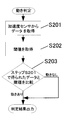
- FIG. 2 is a flowchart showing determination performed by the state determination unit 125 using data from the acceleration sensor 124.
- FIG. 3 is a flowchart illustrating determination performed by the state determination unit 125 using data from the optical sensor 117.
- FIG. 4 is a flowchart for determining the state of the mobile phone 100 according to each result obtained by the flowcharts shown in FIGS. 2 and 3. As shown in FIGS. 2 to 4, the state determination unit 125 changes the mobile phone 100 from a bright place to a dark place or from a dark place to a bright place based on the data from the optical sensor 117 and the acceleration sensor 124. Determine the moved state.
- step S ⁇ b> 201 the state determination unit 125 acquires data detected by the acceleration sensor 124.
- step S202 a threshold value to be compared with the data obtained in step S201 is acquired and stored in the memory 116.
- step S203 the state determination unit 125 compares the data obtained in step S201 with the threshold obtained in step S202, and determines whether or not the mobile phone 100 has been moved.
- the state determination unit 125 determines that the mobile phone 100 has been moved when the value indicated by the data obtained in step S201 is greater than the threshold value. For example, when the user takes out the mobile phone 100 from a bag, a bag or the like, it is determined in step S203 that the mobile phone 100 has been moved.
- step S ⁇ b> 301 the state determination unit 125 acquires data indicating the illuminance measured by the optical sensor 117.
- step S302 the state determination unit 125 acquires data previously stored in the memory 116.
- step S303 the state determination unit 125 compares the data obtained in step S301 with the data obtained in step S302, and determines whether or not the illuminance has changed.
- the state determination unit 125 determines that the illuminance has changed when the difference between the value indicated by the data obtained in step S301 and the value indicated by the data obtained in step S302 is greater than a threshold value. For example, when the user takes out the mobile phone 100 from a bag or a bag that is closed in a bright space, or when the opposite action is performed, it is determined in step S303 that the illuminance has changed.
- step S304 the data obtained in step S301 is stored in the memory 116.
- step S305 it is determined whether the change in illuminance is “change from light to dark” or “change from dark to light”.
- the state determination unit 125 determines “change from light to dark” when the value indicated by the data obtained in step S301 is equal to or less than the value indicated by the data obtained in step S302, and the data obtained in step S301. When the value indicated by is greater than the value indicated by the data obtained in step S302, it is determined that “change from dark to bright”.
- step S303 determines “change from light to dark” when the value indicated by the data obtained in step S301 is equal to or less than the value indicated by the data obtained in step S302, and the data obtained in step S301.
- the value indicated by is greater than the value indicated by the data obtained in step S302
- a determination result of “no change” is output.
- step S401 the motion determination shown in the flowchart of FIG. 2 is performed, and in step S402, the presence or absence of motion is determined. If it is determined that “no movement”, the process proceeds to step S404, and “no movement” is output as a state determination result. On the other hand, if it is determined that “there is motion”, the process proceeds to step S403.
- step S403 the illuminance change determination shown in the flowchart of FIG. 3 is performed.
- step S405 the presence / absence of the illuminance change, “change from light to dark”, and “change from dark to light” are determined. If it is determined that “there is no change in illuminance”, the process proceeds to step 406, where “there is motion but no change in illuminance” is output as the state determination result. If it is determined that “change from dark to light”, the process proceeds to step S407, and “dark ⁇ light change” is output as a state determination result. On the other hand, if it is determined that “change from light to dark”, the process proceeds to step S408, and “change from light to dark” is output as the state determination result.
- the mobile phone 100 is moved from a dark place to a bright place by the state determination unit 125 while the mobile phone 100 is receiving an incoming call (“with motion” and “dark ⁇ bright change”). ”), Mute the ringtone or decrease the volume. For this reason, when taking out the mobile phone 100 from a bag, a bag, or the like, the surroundings are not disturbed.
- the CPU 121 shifts the mobile phone 100 to the absence mode that is in the answering machine state or the message memo state.
- the state determination unit 125 determines that the mobile phone 100 has been moved from a dark place to a bright place (“with motion” and “dark ⁇ bright change”). The unit 125 instructs the CPU 121 to extend the time for transitioning to the absent mode or not to transition to the absent mode.
- the state determination unit 125 determines that the mobile phone 100 has been moved from a dark place to a bright place (“motion is present” and “dark ⁇ bright change”)
- the time held by the timer / RTC 120 is set. Displayed on the LCD 114. Note that the amount of light applied to the LCD 114 is adjusted by the backlight control unit 115 according to the illuminance measured by the optical sensor 114. By performing this adjustment, power consumption is reduced.
- the state determination unit 125 determines that the mobile phone 100 has been moved from a bright place to a dark place (“moving” and “bright ⁇ dark change”). All incoming operations such as generation of a ringing tone by the unit 113, vibration by the vibration motor 111, and lighting or blinking of the LED 122 are stopped. However, only vibration by the vibrator motor 111 may be performed.
- the LED 122 blinks.
- the state determination unit 125 determines that the mobile phone 100 has been moved from a dark place to a bright place (“with motion” and “dark ⁇ bright change”).
- sound, vibration, lighting or blinking of light, etc. are performed.
- the missed call state or the unread mail state is recorded in the memory 116.
- the mobile electronic device according to the present invention is useful as a mobile phone or the like in which optimal user support is performed depending on the state and operation of the mobile electronic device, thereby improving user operability.
Landscapes
- Engineering & Computer Science (AREA)
- Signal Processing (AREA)
- Telephone Function (AREA)
Abstract
Dispositif électronique mobile permettant de recevoir une terminaison d'un réseau externe. Le dispositif électronique mobile comprend une unité d'indication de terminaison pour indiquer la terminaison, une unité de mesure de luminance pour mesurer la luminance de la périphérie du dispositif électronique mobile, une unité de détection d'accélération pour détecter l'accélération du dispositif électronique mobile, et une unité de décision d'état pour décider de l'état du dispositif électronique mobile selon l'accélération détectée par l'unité de détection d'accélération et la luminance mesurée par l'unité de mesure de luminance. L'unité de décision d'état commande l'unité d'indication de terminaison pour modifier la sortie indiquant la terminaison, lorsque l'accélération détectée par l'unité de détection d'accélération est supérieure à une valeur seuil et lorsque le changement de la luminance mesurée par l'unité de mesure de luminance est supérieur à une valeur prédéterminée.
Priority Applications (1)
| Application Number | Priority Date | Filing Date | Title |
|---|---|---|---|
| US12/837,056 US20100279661A1 (en) | 2008-01-17 | 2010-07-15 | Portable electronic device |
Applications Claiming Priority (2)
| Application Number | Priority Date | Filing Date | Title |
|---|---|---|---|
| JP2008-007972 | 2008-01-17 | ||
| JP2008007972A JP2009171302A (ja) | 2008-01-17 | 2008-01-17 | 携帯電子機器 |
Related Child Applications (1)
| Application Number | Title | Priority Date | Filing Date |
|---|---|---|---|
| US12/837,056 Continuation US20100279661A1 (en) | 2008-01-17 | 2010-07-15 | Portable electronic device |
Publications (1)
| Publication Number | Publication Date |
|---|---|
| WO2009090691A1 true WO2009090691A1 (fr) | 2009-07-23 |
Family
ID=40885103
Family Applications (1)
| Application Number | Title | Priority Date | Filing Date |
|---|---|---|---|
| PCT/JP2008/002182 Ceased WO2009090691A1 (fr) | 2008-01-17 | 2008-08-08 | Dispositif électronique mobile |
Country Status (3)
| Country | Link |
|---|---|
| US (1) | US20100279661A1 (fr) |
| JP (1) | JP2009171302A (fr) |
| WO (1) | WO2009090691A1 (fr) |
Families Citing this family (14)
| Publication number | Priority date | Publication date | Assignee | Title |
|---|---|---|---|---|
| US8552859B2 (en) * | 2009-09-30 | 2013-10-08 | Apple Inc. | Self adapting alert device |
| KR101649643B1 (ko) * | 2010-02-01 | 2016-08-19 | 엘지전자 주식회사 | 정보 표시 장치 |
| JP5310591B2 (ja) * | 2010-02-14 | 2013-10-09 | ブラザー工業株式会社 | 通信システムおよびヘッドマウントディスプレイ |
| CN101854435B (zh) * | 2010-05-31 | 2017-04-12 | 华为终端有限公司 | 信息处理方法及用户设备 |
| US9366749B2 (en) * | 2011-04-15 | 2016-06-14 | Qualcomm Incorporated | Device position estimates from motion and ambient light classifiers |
| KR20140023082A (ko) * | 2012-08-16 | 2014-02-26 | 삼성전자주식회사 | 수신 호를 처리하기 위한 방법 및 그 전자장치 |
| JP2014112792A (ja) * | 2012-12-05 | 2014-06-19 | Fujitsu Ltd | 情報処理装置、情報処理方法及び情報処理プログラム |
| JP2015015600A (ja) * | 2013-07-04 | 2015-01-22 | シャープ株式会社 | 携帯端末、制御方法 |
| JP2014082793A (ja) * | 2014-01-30 | 2014-05-08 | Kyocera Corp | 携帯通信端末装置 |
| US20150256685A1 (en) * | 2014-03-10 | 2015-09-10 | Google Inc. | Systems and methods for controlling duration of an incoming call notification for a mobile computing device |
| US10420031B2 (en) | 2015-06-12 | 2019-09-17 | Motorola Mobility Llc | Method and apparatus for in-pocket detection by an electronic device |
| US20170052613A1 (en) * | 2015-08-18 | 2017-02-23 | Motorola Mobility Llc | Method and Apparatus for In-Purse Detection by an Electronic Device |
| US10348883B2 (en) * | 2015-09-28 | 2019-07-09 | Sharp Kabushiki Kaisha | Control device, electronic apparatus, control program, and storage medium |
| JP6717333B2 (ja) * | 2018-03-23 | 2020-07-01 | 株式会社デンソー | 露出制御装置 |
Citations (2)
| Publication number | Priority date | Publication date | Assignee | Title |
|---|---|---|---|---|
| JP2000124970A (ja) * | 1998-10-16 | 2000-04-28 | Nec Shizuoka Ltd | 移動電話端末および報知信号の制御方法 |
| JP2000295318A (ja) * | 1999-04-02 | 2000-10-20 | Matsushita Electric Ind Co Ltd | 携帯電話装置 |
Family Cites Families (5)
| Publication number | Priority date | Publication date | Assignee | Title |
|---|---|---|---|---|
| KR100351886B1 (ko) * | 1997-05-19 | 2002-09-12 | 아사히 메디칼 가부시키가이샤 | 혈액 정제용 폴리술폰형 중공사막 및 그의 제조 방법 |
| JP4779264B2 (ja) * | 2001-09-05 | 2011-09-28 | ヤマハ株式会社 | 移動通信端末、楽音生成システム、楽音生成装置および楽音情報提供方法 |
| US9201469B2 (en) * | 2003-10-16 | 2015-12-01 | Vodafone Group Plc | Mobile communication terminal and application program |
| TWI293000B (en) * | 2005-11-03 | 2008-01-21 | Benq Corp | Electronic device capable of operating a function according to detection of environmental light |
| TWI338492B (en) * | 2007-01-05 | 2011-03-01 | Primax Electronics Ltd | Communication device |
-
2008
- 2008-01-17 JP JP2008007972A patent/JP2009171302A/ja not_active Withdrawn
- 2008-08-08 WO PCT/JP2008/002182 patent/WO2009090691A1/fr not_active Ceased
-
2010
- 2010-07-15 US US12/837,056 patent/US20100279661A1/en not_active Abandoned
Patent Citations (2)
| Publication number | Priority date | Publication date | Assignee | Title |
|---|---|---|---|---|
| JP2000124970A (ja) * | 1998-10-16 | 2000-04-28 | Nec Shizuoka Ltd | 移動電話端末および報知信号の制御方法 |
| JP2000295318A (ja) * | 1999-04-02 | 2000-10-20 | Matsushita Electric Ind Co Ltd | 携帯電話装置 |
Also Published As
| Publication number | Publication date |
|---|---|
| JP2009171302A (ja) | 2009-07-30 |
| US20100279661A1 (en) | 2010-11-04 |
Similar Documents
| Publication | Publication Date | Title |
|---|---|---|
| WO2009090691A1 (fr) | Dispositif électronique mobile | |
| US7194248B2 (en) | Apparatus and method for performing power saving control of mobile terminal | |
| US9094932B2 (en) | Mobile electronic device | |
| EP1858232B1 (fr) | Appareil de sortie audio, methode de commande de sortie d alarme et programme de commande correspondants | |
| JP4982705B2 (ja) | アクセサリに関連するサウンド出力の選択 | |
| US8744533B2 (en) | Mobile communication terminal apparatus | |
| EP3379813A1 (fr) | Terminal mobile et procédé de traitement d'évènement | |
| CN102802137B (zh) | 防止通话中断的系统及方法 | |
| KR20140018032A (ko) | 휴대용 단말기에서 상황인식을 이용한 알람 서비스 방법 및 장치 | |
| JP2004129120A (ja) | バイブレータ制御機能付き無線電話機及び無線電話機のバイブレータ制御方法 | |
| US20140347188A1 (en) | Auto-adjust of indication characteristics based on user proximity | |
| JP2011066476A (ja) | 携帯端末装置、その制御方法、およびコンピュータプログラム | |
| JP2009206868A (ja) | 携帯通信端末、着信報知方法 | |
| US8670367B2 (en) | Mobile terminal, method and program of notifying incoming call for mobile terminal | |
| EP1499092B1 (fr) | Appareil mobile | |
| JP5029339B2 (ja) | 移動通信端末装置 | |
| JP2011066754A (ja) | 携帯通信端末、表示制御プログラムおよび表示制御方法 | |
| JP2006352765A (ja) | 携帯端末、着信モード切り替え方法及び着信モード切り替えプログラム | |
| JP4260640B2 (ja) | 携帯通信端末 | |
| JP5205331B2 (ja) | 携帯情報端末 | |
| JP2012049896A (ja) | 端末装置及びその着信通知方法並びにそのプログラム | |
| JP2003152826A (ja) | 携帯電話機の音量調節方法と音量設定機能を備えた携帯電話機 | |
| JP2006325041A (ja) | 着信通知システム、方法、プログラム及び携帯電話機 | |
| US20110102175A1 (en) | Communication Devices and Methods for Devices Including Generic Indicators Configurable for Real-Time Announcement of Received Communication Signals | |
| KR20020078967A (ko) | 이동통신단말기에서의 문자슬라이딩을 이용한 스케줄 알림방법 |
Legal Events
| Date | Code | Title | Description |
|---|---|---|---|
| 121 | Ep: the epo has been informed by wipo that ep was designated in this application |
Ref document number: 08870824 Country of ref document: EP Kind code of ref document: A1 |
|
| NENP | Non-entry into the national phase |
Ref country code: DE |
|
| 122 | Ep: pct application non-entry in european phase |
Ref document number: 08870824 Country of ref document: EP Kind code of ref document: A1 |