WO2009090699A1 - Mécanisme d'engrenage avec limiteur de couple - Google Patents
Mécanisme d'engrenage avec limiteur de couple Download PDFInfo
- Publication number
- WO2009090699A1 WO2009090699A1 PCT/JP2008/003296 JP2008003296W WO2009090699A1 WO 2009090699 A1 WO2009090699 A1 WO 2009090699A1 JP 2008003296 W JP2008003296 W JP 2008003296W WO 2009090699 A1 WO2009090699 A1 WO 2009090699A1
- Authority
- WO
- WIPO (PCT)
- Prior art keywords
- gear
- torque limiter
- felt
- gear mechanism
- felt member
- Prior art date
- Legal status (The legal status is an assumption and is not a legal conclusion. Google has not performed a legal analysis and makes no representation as to the accuracy of the status listed.)
- Ceased
Links
Images





Classifications
-
- F—MECHANICAL ENGINEERING; LIGHTING; HEATING; WEAPONS; BLASTING
- F16—ENGINEERING ELEMENTS AND UNITS; GENERAL MEASURES FOR PRODUCING AND MAINTAINING EFFECTIVE FUNCTIONING OF MACHINES OR INSTALLATIONS; THERMAL INSULATION IN GENERAL
- F16D—COUPLINGS FOR TRANSMITTING ROTATION; CLUTCHES; BRAKES
- F16D7/00—Slip couplings, e.g. slipping on overload, for absorbing shock
- F16D7/02—Slip couplings, e.g. slipping on overload, for absorbing shock of the friction type
- F16D7/024—Slip couplings, e.g. slipping on overload, for absorbing shock of the friction type with axially applied torque limiting friction surfaces
- F16D7/025—Slip couplings, e.g. slipping on overload, for absorbing shock of the friction type with axially applied torque limiting friction surfaces with flat clutching surfaces, e.g. discs
-
- F—MECHANICAL ENGINEERING; LIGHTING; HEATING; WEAPONS; BLASTING
- F16—ENGINEERING ELEMENTS AND UNITS; GENERAL MEASURES FOR PRODUCING AND MAINTAINING EFFECTIVE FUNCTIONING OF MACHINES OR INSTALLATIONS; THERMAL INSULATION IN GENERAL
- F16H—GEARING
- F16H35/00—Gearings or mechanisms with other special functional features
- F16H35/10—Arrangements or devices for absorbing overload or preventing damage by overload
-
- F—MECHANICAL ENGINEERING; LIGHTING; HEATING; WEAPONS; BLASTING
- F16—ENGINEERING ELEMENTS AND UNITS; GENERAL MEASURES FOR PRODUCING AND MAINTAINING EFFECTIVE FUNCTIONING OF MACHINES OR INSTALLATIONS; THERMAL INSULATION IN GENERAL
- F16H—GEARING
- F16H55/00—Elements with teeth or friction surfaces for conveying motion; Worms, pulleys or sheaves for gearing mechanisms
- F16H55/02—Toothed members; Worms
- F16H55/17—Toothed wheels
Definitions
- This invention relates to a gear mechanism with a torque limiter that suppresses driving when an excessive load is applied.
- a gear mechanism with a torque limiter is provided to prevent damage caused by a user's fingers being pinched or damage to mechanical parts due to external force.
- the gear mechanism with a torque limiter is configured such that a felt member is sandwiched between a large-diameter gear and a small-diameter gear arranged on the same axis so that the felt member rotates together with each gear, and the friction of the felt member There is one that transmits the rotation of one gear to the other gear by force.
- a felt member that rotates together with the one gear when an excessive load is applied to the other gear has the other gear. Slips on the contact surface of the motor and suppresses torque transmission to the other gear.
- a long hole is provided in each of the large-diameter gear and the small-diameter gear arranged on the same axis, a rigid sphere is disposed in the elongated hole, and the rigid sphere is sandwiched between two metal friction plates so that a high torque can be obtained.
- the conventional gear mechanism with a torque limiter is configured as described above, when a large driving torque is required due to an increase in the size of the display unit, it is necessary to increase the force for pinching the felt member of the gear with the torque limiter. In this way, when the pinching force is increased, the thickness of the felt member gradually decreases, and the convex portion provided on one gear or the like passes through the felt member in order to stabilize the slip generation of the felt member, and the other gear The tip part of the convex part comes into contact with each other, and the suppression operation based on a constant torque limit value becomes unstable. In addition, abnormal noise is generated by contact of these portions. Moreover, when a metal steel ball, a friction plate, or the like is used, there is a problem that it is difficult to reduce the size and weight.
- the present invention has been made to solve the above-described problems. Even when the felt member becomes thin, it slips when the torque exceeds a predetermined value, and abnormal noise is generated. An object is to obtain a gear mechanism with a torque limiter that does not occur.
- a plurality of convex portions are arranged concentrically on the surface of one gear in contact with the felt member, and concentric grooves corresponding to the convex portions are formed on the surface of the other gear. It is provided.
- the concentric groove portion is provided on the surface of the other gear in correspondence with the convex portion provided on the surface of the one gear in contact with the felt member, the thickness of the felt member is reduced due to a change over time. Even if the convex portion penetrates the felt member, it is possible to prevent contact between the tip portion of each convex portion of one gear and the other gear, and the occurrence of slip due to the set torque limit value is ensured, It is possible to perform a stable suppression operation based on the torque limit value and to prevent the generation of abnormal noise due to contact.
- FIG. 3 is an explanatory diagram illustrating a configuration of a gear mechanism with a torque limiter according to the first embodiment.
- FIG. 3 is an explanatory diagram illustrating a configuration of a gear mechanism with a torque limiter according to the first embodiment.
- FIG. 6 is an explanatory diagram showing a small gear of the gear mechanism with a torque limiter according to the first embodiment.
- FIG. 5 is an explanatory diagram showing a large gear of the gear mechanism with a torque limiter according to the first embodiment. It is explanatory drawing which shows the gear mechanism with a general torque limiter.
- FIG. 1 is an explanatory diagram showing a schematic configuration of an in-vehicle video device using a gear mechanism with a torque limiter according to Embodiment 1 of the present invention.
- FIG. 1 shows only a portion related to the gear mechanism with a torque limiter according to the present invention, and does not show other portions.
- the illustrated in-vehicle video device 1 meshes with a display unit 2 composed of a video display device such as an LCD, a motor 3 as a driving source for moving the display unit 2, a worm gear 4 attached to a rotating shaft of the motor 3, and a worm gear 4.
- a worm wheel 5 for example, a support member 6 that is connected to the lower ends on both sides of the display unit 2 and moves the lower side of the display unit 2 in the front-rear direction of the video display device by the rotation of the worm wheel 5,
- a transmission gear 7 that transmits the rotation / driving force to the support member 6,
- a position sensor 8 that detects the position of the moved display unit 2 or the support member 6, and the like are provided.
- the display unit 2 in FIG. 1 has the display screen directed to the back side in the figure. Further, the display unit 2 is in a state in which the display screen is in a horizontal state from a vertical state by moving the lower part of the display unit 2 connected to the support member 6 from the front side to the rear side in the figure as described above. Both sides of the display unit 2 so that the display screen transitions from a horizontal state to a vertical state by moving the lower part of the display unit 2 from the rear side to the front side in the figure. Is supported by a guide member (not shown).
- the two-stage gear having the worm wheel 5 shown in FIG. 1 corresponds to a gear mechanism 10 with a torque limiter described later, and the worm wheel 5 meshing with the worm gear 4 in FIG. A portion not shown corresponds to a small gear 13 described later.
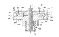
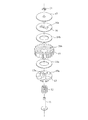
- FIG. 2 and 3 are explanatory views showing the configuration of the gear mechanism with a torque limiter according to the first embodiment.
- FIG. 2 is a longitudinal sectional view of the gear mechanism with torque limiter 10 having the mechanism according to the first embodiment
- FIG. 3 is an exploded perspective view of the gear mechanism 10 with torque limiter. 2 and 3, the same reference numerals are used for the same parts to represent each part.
- the gear mechanism 10 with a torque limiter includes a coil spring 12, a small gear 13 that is a first gear, a felt member 14a that is a second felt member, a large gear 15 that is a second gear, and a felt that is a first felt member.
- the member 14b, the synchronizing member 16, and the pressing plate 17 are laminated in the above order.
- the support shaft 11 having the flange portion 11 a at one end is inserted into the through hole portion of each member, and more specifically, the lower end portion of the coil spring 12 is in contact with the flange portion 11 a. Is inserted from below. That is, the small gear 13 and the large gear 15 are coaxially arranged, and the felt member 14 a is sandwiched between the upper surface of the small gear 13 and the lower surface of the large gear 15. The felt member 14 b is sandwiched between the upper surface of the large gear 15 and the lower surface of the synchronization member 16.
- the coil spring 12 is provided so as to be urged in the axial direction of the support shaft 11, that is, upward in the figure, and by this urging force, the small gear 13, the felt member 14a, the large gear 15, the felt member 14b, the synchronizing member 16, and The holding plate 17 is pushed upward. Further, the holding plate 17 is positioned and fixed by an E-ring 21 of a stopper fixed to the upper end portion of the support shaft 11. In this way, the above-mentioned member through which the support shaft 11 is inserted is brought into close contact with the urging force of the coil spring 12.
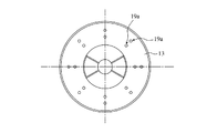
- FIG. 4 is an explanatory diagram showing a small gear of the gear mechanism with a torque limiter according to the first embodiment.
- the same reference numerals are used for the same parts as those shown in FIG.
- This figure shows the shape of the small gear 13 shown in FIGS. 2 and 3 as viewed from above, that is, the top surface.
- the upper surface of the small gear 13, that is, the surface in contact with the felt member 14a, is provided with a plurality of, for example, cone-shaped protrusions 19a that are difficult to slip and prevent slipping between the upper surface of the small gear 13 and the felt member 14a.
- the convex portions 19 a are arranged concentrically with the small gear 13. Note that the number of convex portions 19a is set according to the magnitude of the transmission torque.
- the convex part 19a slips into the lower surface of the felt member 14a, or stabs to suppress the slip between the felt member 14a and the small gear 13, and slip based on the torque limit value set in the gear mechanism 10 with the torque limiter. It is provided to reduce variation in operation.
- the felt member 14 a is a surface on which the surface that contacts the lower surface of the large gear 15 is slipped. Further, as shown in FIG.
- a joint portion 13 a that protrudes from the top surface and joins or joins a joint hole 16 a of the synchronization member 16 described later is provided at the center of the upper surface of the small gear 13. Yes.
- the small gear 13 illustrated here includes gear teeth protruding downward from the lower surface.
- FIG. 5 is an explanatory view showing a large gear of the gear mechanism with a torque limiter according to the first embodiment.
- the same reference numerals are used for the same parts as those shown in FIG.
- This figure shows the shape of the large gear 15 shown in FIGS. 2 and 3 as viewed from below, that is, the lower surface of the large gear 15.
- a circular groove 20a is provided on the lower surface of the large gear 15, that is, the surface in contact with the felt member 14a so as to correspond to the arrangement of the convex portions 19a of the small gear 13.
- the groove portion 20a is formed so as to be concentric with the large gear 15, and has the same distance as the distance from the rotation axis center of the small gear 13 to the convex portion 19a, that is, the arrangement radius of the convex portion 19a.
- a plurality of groove portions 20a are also provided.
- groove portions 20a having the same radius as the respective arrangement radii of the convex portions 19a are provided.
- a groove portion 20 b is provided on the upper surface of the large gear 15 so as to correspond to a convex portion 19 b of the synchronization member 16 described later.
- the groove portion 20b has a circular shape having the same radius as the arrangement radius of each protrusion portion 19b, like the groove portion 20a corresponding to the protrusion portion 19a.
- the large gear 15 illustrated here is provided with gear teeth at the circumferential portion.
- the felt member 14b is also in contact with the upper surface of the large gear 15 that is in contact with the lower surface of the felt member 14a.
- the felt member 14a and the felt member 14b are made of the same material and have the same shape. Specifically, a predetermined frictional force is generated on each large gear 15 by the urging force of the coil spring 12, and each contact surface of the large gear, specifically the large gear 15 is applied when a torque exceeding a set torque limit value is applied. And a through-hole having a diameter through which the joint portion 13a of the small gear 13 is inserted is formed in the center portion.
- the synchronization member 16 is provided with a joint hole 16 a for joining the joint 13 a of the small gear 13 at the center of the synchronization member 16, and is integrated with the small gear 13 to be a support shaft. 11 is configured to rotate about the center.
- the synchronization member 16 has a plurality of convex portions 19b concentrically arranged on the lower surface, that is, the surface in contact with the felt member 14b, like the plurality of convex portions 19a provided on the small gear 13. Has been.
- the convex portion 19b is set in the gear mechanism 10 with the torque limiter in the same manner as the convex portion 19a by suppressing the slip between the felt member 14b and the synchronizing member 16 by being inserted into the upper surface of the felt member 14b or stuck. It is provided in order to reduce the variation of the slip operation based on the torque limit value.
- the felt member 14 b is a surface that slips a surface that contacts the upper surface of the large gear 15. Further, in order to increase the biasing force of the coil spring 2 when dealing with a high torque limit value, the hard pressing plate 17 is configured to contact the E-ring 21 so that the synchronizing member 16 is not deformed by the biasing force.
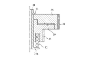
- FIG. 6 and 7 are explanatory views showing a general gear mechanism with a torque limiter.
- FIG. 6 shows a state before the felt member 34 changes with time
- FIG. 7 shows that the felt member 34 is thin due to deterioration over time. Shows what has become.
- an E attached to the support shaft 31 is attached to the support shaft 31 with a felt member 34 sandwiched between opposing surfaces of a small gear 33 serving as a first gear and a large gear 35 serving as a second gear.
- the ring 41 restricts the movement of the second gear 35 in the axial direction, and the coil spring 32 that presses the first gear 33 toward the second gear 35 via the felt member 34 is supported with the first gear 33.
- the gear mechanism with torque limiter shown in FIGS. 6 and 7 performs drive transmission between the small gear 33 and the large gear 35 using the frictional force of the felt member 34 generated by the biasing force of the coil spring 32, and these members are Rotate together.
- slip occurs between the upper surface of the felt member 34 and the lower surface of the large gear 35 to suppress torque transmission.
- the felt member 34 is always pressed in a state of being sandwiched between the small gear 33 and the large gear 35 by the urging force of the coil spring 32.
- slip occurs in such a pressure contact state, wear occurs, and the thickness gradually decreases due to the pressure. As shown in FIG.
- the groove portion 20a corresponding to the convex portion 19a of the small gear 13 is provided on the lower surface of the large gear 15, and the convex portion 19b of the synchronizing member 16 is formed on the upper surface of the large gear 15. Since the corresponding groove portion 20b is provided, the thickness of the felt members 14a and 14b is reduced due to aging, so that the convex portion 19a stuck in the felt member 14a penetrates the felt member 14a or is stuck in the felt member 14b.
- the felt contact surface of the large gear 15, that is, the grooves 20a and 20b on the upper surface or the lower surface of the large gear 15, prevents contact with the tip portion of each protruding portion. It is possible to reliably generate slip due to the set torque limit value and to prevent occurrence of abnormal noise due to contact. Therefore, there is an effect that a stable restraining operation based on a constant torque limit value can be performed even when used over time.
- the thickness of the felt members 14a and 14b decreases with time, and even if the felt members 14a and 14b pass through, the convex portions enter the corresponding groove portions, and the convex portions of one gear do not contact the other gear. Therefore, there is an effect that each mechanism component can be configured to be thin.
- FIG. FIG. 8 is an explanatory view showing the configuration of a gear mechanism with a torque limiter according to Embodiment 2 of the present invention.
- the same reference numerals are used for portions that are the same as or correspond to those shown in FIGS.
- the gear mechanism with torque limiter according to the second embodiment is configured in substantially the same manner as the gear mechanism 10 with torque limiter described above.
- the characteristic part of the gear mechanism with a torque limiter according to the second embodiment will be described, and a duplicate description of the part configured in the same manner as that described in the first embodiment will be omitted.
- FIG. 8 is a cross-sectional view of the gear mechanism with torque limiter 10a according to the second embodiment, and shows a portion on one side from the rotation center of the gear mechanism with torque limiter 10a.
- the large gear 15 of the gear mechanism 10a with a torque limiter in FIG. 8 is provided with grooves 20a4 and 20a5 having a depth h1 on the lower surface, and the small gear 13 in FIG. 8 has a convex portion 19a4 having a height h1 ′ on the upper surface. 19a5 is provided.
- the depths h1 of the groove portions 20a4 and 20a5 are configured to have substantially the same dimensions as the height h1 ′ of the convex portions 19a4 and 19a5.
- the large gear 15 in FIG. 8 is provided with grooves 20b1 to 20b3 having a depth h2 on the upper surface, and the synchronizing member 16 in FIG.
- the depth h2 of the grooves 20b1 to 20b3 is configured to have substantially the same dimension as the height h2 ′ of the convex portions 19b1 to 19b3.
- the depth of the grooves 20b1 to 20b3 provided on the upper surface of the large gear 15 is set to be approximately the same as or higher than the height of the convex portions 19b1 to 19b3 provided on the synchronization member 16, and
- the felt members 14a and 14b Even if the thickness is reduced, it is possible to prevent the tip portion of each convex portion from contacting the large gear 15. In other words, contact can be prevented by setting the cross-section of each groove portion orthogonal to the extending direction, that is, the circumferential direction, to be the same size or larger than the outer shape of the convex portion corresponding to the groove portion.
- the convex portion 19b1 of the synchronization member 16 and the groove portion 20b1 of the large gear 15 in FIG. 8 are provided at a distance r1 from the center of the support shaft 11, that is, on the circumference of the arrangement radius r1.
- the convex part 19b2 and the groove part 20b2 are provided on the circumference of the arrangement radius r2
- the convex part 19b3 and the groove part 20b3 are provided on the circumference of the arrangement radius r3.
- the distances r1 to r5 are set so that the relations r4 ⁇ (r1 + r2) / 2 and r5 ⁇ (r2 + r3) / 2 are established.
- the position of the groove portion 20a4 of the large gear 15 is configured to be an intermediate point or a substantially intermediate point between the positions of the convex portion 19b1 of the synchronizing member 16 and the groove portion 20b1 of the large gear 15 and the positions of the convex portion 19b2 and the groove portion 20b2. .
- the position of the convex portion 19a5 of the small gear 13 and the groove portion 20a5 of the large gear 15 is an intermediate point between the position of the convex portion 19b2 of the synchronizing member 16 and the groove portion 20b2 of the large gear 15 and the position of the convex portion 19b3 and the groove portion 20b3.
- it is configured so as to be approximately the middle point.
- the number of each convex part and each groove part shown in FIG. 8 is not limited to what was illustrated.
- the groove portions 20b1 to 20b3 on the upper surface of the large gear 15 and the groove portions 20a4 and 20a5 on the lower surface do not overlap in the vertical direction, and the gap portion between the groove portion 20b1 on the upper surface and the groove portion 20b2
- the groove 20a4 on the lower surface is disposed at a position substantially below the center of the groove
- the groove 20a5 on the lower surface is disposed at a position substantially below the center of the space between the groove 20b2 and the groove 20b3 on the upper surface.
- the depths of the grooves 20b1 to 20b3 provided on the upper surface of the large gear 15 are set to be larger than the heights of the convex portions 19b1 to 19b3 of the synchronization member 16, Since the depth of the groove portions 20a4 and 20a5 provided on the lower surface of 15 is configured to be larger than the height of the convex portions 19a4 and 19a5 of the small gear 13, the thickness of the felts 14a and 14b is gradually reduced so that each convex portion is Even if it penetrates, the tip part of each convex part is prevented from coming into contact with the large gear 15, so that a stable slip operation based on a constant torque limit value is possible, and the occurrence of abnormal noise due to the above contact is prevented.
- the large gear 15 is thin.
- the gear mechanism with torque limiter 10a can be thinned, and each mechanical component can be made thin.
- FIG. 9 is an explanatory view showing the configuration of a gear mechanism with a torque limiter according to Embodiment 3 of the present invention.
- the same reference numerals are used for parts that are the same as or correspond to those shown in FIG.
- FIG. 9 shows a cross section of the large gear 15 and the like of the gear mechanism with torque limiter according to the third embodiment, and the parts not shown are configured in substantially the same manner as described in the first embodiment.
- the convex portions 19a and 19b and the groove portions 20a and 20b shown in FIG. 9 are not limited to the illustrated number.
- the large gear 15 in FIG. 9 is configured so that the plurality of groove portions 20b provided on the upper surface and the plurality of groove portions 20a provided on the lower surface in FIG. For example, they are arranged alternately at equal intervals.
- the depth and width of the groove portions 20a and 20b in other words, the size of the cross section orthogonal to the extending direction of each groove portion, that is, the circumferential direction, is the same as the size of the convex portions 19a and 19b corresponding to each groove portion.
- each portion of the large gear 15 provided with these grooves 20a and 20b is configured to have a thickness d.
- the thickness d 'of the circumferential portion of the large gear 15 provided with gear teeth is the same as the above-described thickness d, and the entire large gear 15 is configured with the same thickness.
- the entire large gear 15 is configured to have the same thickness, the formation of the large gear 15 is facilitated, and the occurrence of warping and deformation is small.
- product variations can be suppressed, and a gear mechanism with a torque limiter that performs a stable suppression operation based on a constant torque limit value can be obtained.
- FIG. 10 is an explanatory view showing the configuration of a gear mechanism with a torque limiter according to Embodiment 4 of the present invention.
- the same reference numerals are used for parts that are the same as or correspond to those shown in FIG.
- FIG. 10 shows a cross section of the large gear 15 and the like of the gear mechanism with a torque limiter according to the fourth embodiment, and the portions not shown are configured in substantially the same manner as those described in the first embodiment. .
- the large gear 15 shown in FIG. 10 has a plurality of groove portions 20b on the upper surface and a plurality of groove portions 20a on the lower surface.
- Each of these groove portions is provided corresponding to each convex portion of the small gear 13 and the synchronization member 16 as described in the first embodiment and the like.
- the convex portions 19a and 19b and the groove portions 20a and 20b shown in FIG. 10 are not limited to the illustrated number.
- the large gear 15 in FIG. 10 is provided with a plurality of grooves 20c at intervals between the grooves 20a provided on the upper surface.
- two grooves 20 c are provided in each of the above-described spacing portions.
- Each groove 20 c is concentric with the groove 20 a, the groove 20 b, or the large gear 15.
- each groove 20 c is provided at a position that does not correspond to each convex portion of the small gear 13 and the synchronization member 16.
- the large gear 15 is provided with a plurality of grooves 20c to form a felt contact portion.
- the groove 20c shown in FIG. 10 is provided so that the space between the adjacent groove 20c has an edge shape.
- a plurality of edge portions formed by a plurality of grooves 20c provided at each interval of the groove portions 20b are in contact with the felt member 14b, and a plurality of grooves formed by a plurality of grooves 20c provided at each interval of the groove portions 20a.
- Each surface which contacts the felt members 14a and 14b of the large gear 15 is configured so that the edge portion of the large gear 15 contacts the felt member 14a.
- the plurality of grooves 20c that are concentric with the large gear 15 are formed at positions that do not correspond to the convex portions provided on the small gear 13 and the synchronization member 16.
- the large gear 15 can be reduced in weight, the contact area between the large gear 15 and the felt members 14a, 14b is reduced, and the felt members 14a, 14b are guided by the grooves 20c and reliably slip.
- a stable suppression operation can be performed based on a constant torque limit value.
- the gap portions of the grooves 20c are formed in an edge shape and the edge portions are in contact with the felt members 14a and 14b, the felt members 14a and 14b guided by the groove portions 20c are surely slipped. Thus, there is an effect that a stable suppression operation can be performed based on a constant torque limit value.
- the groove portions 20a and 20b are provided on the upper and lower surfaces of the large gear 15, and the convex portions 19a and 19b are formed on the surfaces of the small gear 13 and the synchronization member 16 that are opposed to each other through the felt members 14a and 14b.
- convex part 19a, 19b is provided in the upper and lower surfaces of the large gear 15, and each groove
- the same effect as the embodiment can be obtained.
- a concentric groove is provided on the surface of the other gear so as to correspond to the convex portion provided on the surface of the one gear in contact with the felt member. Even if the thickness of the felt member becomes thin due to changes over time and the convex part penetrates the felt member, it is possible to prevent contact between the tip part of each convex part of one gear and the other gear. The occurrence of slip due to the torque limit value is ensured, stable suppression operation based on the torque limit value can be performed, and abnormal noise due to contact can be prevented, and a gear mechanism with a torque limiter is used. Suitable for use in in-vehicle video equipment.
Landscapes
- Engineering & Computer Science (AREA)
- General Engineering & Computer Science (AREA)
- Mechanical Engineering (AREA)
- Transmission Devices (AREA)
- Gears, Cams (AREA)
- One-Way And Automatic Clutches, And Combinations Of Different Clutches (AREA)
Abstract
Priority Applications (4)
| Application Number | Priority Date | Filing Date | Title |
|---|---|---|---|
| US12/742,053 US8308575B2 (en) | 2008-01-17 | 2008-11-12 | Gear mechanism with torque limiter |
| CN200880118710.7A CN101874168B (zh) | 2008-01-17 | 2008-11-12 | 带扭矩限制器的齿轮机构 |
| JP2009549902A JP5094881B2 (ja) | 2008-01-17 | 2008-11-12 | トルクリミッタ付きギア機構 |
| DE112008003271.8T DE112008003271B4 (de) | 2008-01-17 | 2008-11-12 | Getriebemechanismus mit Drehmomentbegrenzer |
Applications Claiming Priority (2)
| Application Number | Priority Date | Filing Date | Title |
|---|---|---|---|
| JP2008-008207 | 2008-01-17 | ||
| JP2008008207 | 2008-01-17 |
Publications (1)
| Publication Number | Publication Date |
|---|---|
| WO2009090699A1 true WO2009090699A1 (fr) | 2009-07-23 |
Family
ID=40885110
Family Applications (1)
| Application Number | Title | Priority Date | Filing Date |
|---|---|---|---|
| PCT/JP2008/003296 Ceased WO2009090699A1 (fr) | 2008-01-17 | 2008-11-12 | Mécanisme d'engrenage avec limiteur de couple |
Country Status (5)
| Country | Link |
|---|---|
| US (1) | US8308575B2 (fr) |
| JP (1) | JP5094881B2 (fr) |
| CN (1) | CN101874168B (fr) |
| DE (1) | DE112008003271B4 (fr) |
| WO (1) | WO2009090699A1 (fr) |
Families Citing this family (9)
| Publication number | Priority date | Publication date | Assignee | Title |
|---|---|---|---|---|
| US20140209417A1 (en) * | 2013-01-30 | 2014-07-31 | Xiu-Feng Chen | Brake structure for hoist |
| US9927838B2 (en) | 2013-12-31 | 2018-03-27 | Henge Docks Llc | Sensor system for docking station |
| US9650814B2 (en) | 2013-12-31 | 2017-05-16 | Henge Docks Llc | Alignment and drive system for motorized horizontal docking station |
| JP6591171B2 (ja) * | 2015-02-16 | 2019-10-16 | ミネベアミツミ株式会社 | トルクリミッタ及び駆動装置 |
| US9575510B1 (en) | 2015-10-23 | 2017-02-21 | Matthew Leigh Vroom | Precision docking station for an electronic device having integrated retention mechanism |
| US9811118B2 (en) | 2015-10-23 | 2017-11-07 | Henge Docks Llc | Secure assembly for a docking station |
| US9727084B2 (en) | 2015-10-23 | 2017-08-08 | Henge Docks Llc | Drivetrain for a motorized docking station |
| EP3705248A4 (fr) * | 2017-10-31 | 2021-08-18 | Koki Holdings Co., Ltd. | Outil de puissance |
| US10365688B1 (en) | 2018-04-19 | 2019-07-30 | Henge Docks Llc | Alignment sleeve for docking station |
Citations (4)
| Publication number | Priority date | Publication date | Assignee | Title |
|---|---|---|---|---|
| JPS62140263A (ja) * | 1985-12-13 | 1987-06-23 | Hitachi Ltd | フエルトクラツチ機構 |
| JPH0317455U (fr) * | 1989-06-30 | 1991-02-21 | ||
| JPH0484831U (fr) * | 1990-11-30 | 1992-07-23 | ||
| JP2007292265A (ja) * | 2006-04-27 | 2007-11-08 | Seiko Epson Corp | 歯車及びこれを用いたプリンタ |
Family Cites Families (8)
| Publication number | Priority date | Publication date | Assignee | Title |
|---|---|---|---|---|
| US3386122A (en) * | 1965-12-13 | 1968-06-04 | Robert V. Mathison | Rotatable disc devices |
| AT346084B (de) * | 1974-12-16 | 1978-10-25 | Philips Nv | Rutschkupplung fuer ein aufzeichnungs- und/oder wiedergabegeraet |
| IT1026359B (it) * | 1975-01-15 | 1978-09-20 | Spem Srl | Dispositivo di frizione a carico constante specialmente adatto per l applicazione nei registratori a nastro |
| JPH0484831A (ja) * | 1990-03-22 | 1992-03-18 | Isao Arai | 栽培ベッド |
| JP2002358701A (ja) * | 2001-05-29 | 2002-12-13 | Matsushita Electric Ind Co Ltd | トルクリミッタおよびリール台 |
| JP2004239357A (ja) * | 2003-02-06 | 2004-08-26 | Nifco Inc | トルクリミッタ |
| JP4262527B2 (ja) | 2003-06-05 | 2009-05-13 | アルパイン株式会社 | トルクリミッタ付きギアおよび電子機器の動力伝達機構 |
| CN2682246Y (zh) * | 2004-02-24 | 2005-03-02 | 常州雷利电器有限公司 | 大转距摩擦打滑式输出轴 |
-
2008
- 2008-11-12 US US12/742,053 patent/US8308575B2/en not_active Expired - Fee Related
- 2008-11-12 WO PCT/JP2008/003296 patent/WO2009090699A1/fr not_active Ceased
- 2008-11-12 JP JP2009549902A patent/JP5094881B2/ja not_active Expired - Fee Related
- 2008-11-12 CN CN200880118710.7A patent/CN101874168B/zh not_active Expired - Fee Related
- 2008-11-12 DE DE112008003271.8T patent/DE112008003271B4/de not_active Expired - Fee Related
Patent Citations (4)
| Publication number | Priority date | Publication date | Assignee | Title |
|---|---|---|---|---|
| JPS62140263A (ja) * | 1985-12-13 | 1987-06-23 | Hitachi Ltd | フエルトクラツチ機構 |
| JPH0317455U (fr) * | 1989-06-30 | 1991-02-21 | ||
| JPH0484831U (fr) * | 1990-11-30 | 1992-07-23 | ||
| JP2007292265A (ja) * | 2006-04-27 | 2007-11-08 | Seiko Epson Corp | 歯車及びこれを用いたプリンタ |
Also Published As
| Publication number | Publication date |
|---|---|
| CN101874168B (zh) | 2013-05-01 |
| DE112008003271T5 (de) | 2010-10-07 |
| CN101874168A (zh) | 2010-10-27 |
| US20100243398A1 (en) | 2010-09-30 |
| US8308575B2 (en) | 2012-11-13 |
| JPWO2009090699A1 (ja) | 2011-05-26 |
| DE112008003271B4 (de) | 2015-06-18 |
| JP5094881B2 (ja) | 2012-12-12 |
Similar Documents
| Publication | Publication Date | Title |
|---|---|---|
| JP5094881B2 (ja) | トルクリミッタ付きギア機構 | |
| US9309705B2 (en) | Dual-shaft synchronous transmission fixing device | |
| CN107614912B (zh) | 离合器装置以及使用了该离合器装置的马达单元 | |
| US9003606B2 (en) | Synchronous movement device applied to dual-shaft system | |
| JP4876833B2 (ja) | トルクリミッタ装置を含む表示装置の台座およびトルクリミッタ装置 | |
| CN104205569B (zh) | 定子芯的卡止构造 | |
| WO2016132949A1 (fr) | Limiteur de couple et dispositif d'entraînement | |
| JP7510185B2 (ja) | クラッチ装置およびモータユニット | |
| JP2017209007A (ja) | モータ | |
| JP4962223B2 (ja) | 動力伝達装置 | |
| JP2009264436A (ja) | トルクリミッタ装置、トルクリミッタ装置を備えた表示画面旋回装置およびトルクリミッタ装置を含むテレビジョン装置 | |
| JP2007247894A (ja) | 歯車及び歯車装置 | |
| JP4262527B2 (ja) | トルクリミッタ付きギアおよび電子機器の動力伝達機構 | |
| JP2012251601A (ja) | ウォーム減速機構とそれを用いた雲台装置 | |
| TW454071B (en) | Differential gear | |
| JP5256958B2 (ja) | 電動式パワーステアリング装置 | |
| JP4610171B2 (ja) | デファレンシャル装置 | |
| JP2007221910A (ja) | モータ | |
| JP2010048355A (ja) | 弾性軸継手及び電動式パワーステアリング装置 | |
| CN108626261A (zh) | 动力传递装置 | |
| JP5275916B2 (ja) | ギヤストッパ | |
| JP4998081B2 (ja) | 円錐摩擦リング式無段変速装置 | |
| JP4645588B2 (ja) | トルクリミッタ装置を含む表示装置の台座およびトルクリミッタ装置 | |
| JP2017077088A (ja) | モータユニット | |
| CN104895951B (zh) | 同步啮合装置 |
Legal Events
| Date | Code | Title | Description |
|---|---|---|---|
| WWE | Wipo information: entry into national phase |
Ref document number: 200880118710.7 Country of ref document: CN |
|
| 121 | Ep: the epo has been informed by wipo that ep was designated in this application |
Ref document number: 08870646 Country of ref document: EP Kind code of ref document: A1 |
|
| WWE | Wipo information: entry into national phase |
Ref document number: 2009549902 Country of ref document: JP |
|
| WWE | Wipo information: entry into national phase |
Ref document number: 12742053 Country of ref document: US |
|
| WWE | Wipo information: entry into national phase |
Ref document number: 1120080032718 Country of ref document: DE |
|
| RET | De translation (de og part 6b) |
Ref document number: 112008003271 Country of ref document: DE Date of ref document: 20101007 Kind code of ref document: P |
|
| 122 | Ep: pct application non-entry in european phase |
Ref document number: 08870646 Country of ref document: EP Kind code of ref document: A1 |