WO2009090835A1 - 電動車両の制御装置およびそれを備えた電動車両、ならびに電動車両の制御方法およびその制御方法をコンピュータに実行させるためのプログラムを記録したコンピュータ読取可能な記録媒体 - Google Patents
電動車両の制御装置およびそれを備えた電動車両、ならびに電動車両の制御方法およびその制御方法をコンピュータに実行させるためのプログラムを記録したコンピュータ読取可能な記録媒体 Download PDFInfo
- Publication number
- WO2009090835A1 WO2009090835A1 PCT/JP2008/073316 JP2008073316W WO2009090835A1 WO 2009090835 A1 WO2009090835 A1 WO 2009090835A1 JP 2008073316 W JP2008073316 W JP 2008073316W WO 2009090835 A1 WO2009090835 A1 WO 2009090835A1
- Authority
- WO
- WIPO (PCT)
- Prior art keywords
- phase
- inverter
- value
- motor
- electric vehicle
- Prior art date
- Legal status (The legal status is an assumption and is not a legal conclusion. Google has not performed a legal analysis and makes no representation as to the accuracy of the status listed.)
- Ceased
Links
Images












Classifications
-
- H—ELECTRICITY
- H02—GENERATION; CONVERSION OR DISTRIBUTION OF ELECTRIC POWER
- H02P—CONTROL OR REGULATION OF ELECTRIC MOTORS, ELECTRIC GENERATORS OR DYNAMO-ELECTRIC CONVERTERS; CONTROLLING TRANSFORMERS, REACTORS OR CHOKE COILS
- H02P27/00—Arrangements or methods for the control of AC motors characterised by the kind of supply voltage
- H02P27/04—Arrangements or methods for the control of AC motors characterised by the kind of supply voltage using variable-frequency supply voltage, e.g. inverter or converter supply voltage
- H02P27/06—Arrangements or methods for the control of AC motors characterised by the kind of supply voltage using variable-frequency supply voltage, e.g. inverter or converter supply voltage using DC to AC converters or inverters
- H02P27/08—Arrangements or methods for the control of AC motors characterised by the kind of supply voltage using variable-frequency supply voltage, e.g. inverter or converter supply voltage using DC to AC converters or inverters with pulse width modulation
-
- B—PERFORMING OPERATIONS; TRANSPORTING
- B60—VEHICLES IN GENERAL
- B60L—PROPULSION OF ELECTRICALLY-PROPELLED VEHICLES; SUPPLYING ELECTRIC POWER FOR AUXILIARY EQUIPMENT OF ELECTRICALLY-PROPELLED VEHICLES; ELECTRODYNAMIC BRAKE SYSTEMS FOR VEHICLES IN GENERAL; MAGNETIC SUSPENSION OR LEVITATION FOR VEHICLES; MONITORING OPERATING VARIABLES OF ELECTRICALLY-PROPELLED VEHICLES; ELECTRIC SAFETY DEVICES FOR ELECTRICALLY-PROPELLED VEHICLES
- B60L15/00—Methods, circuits, or devices for controlling the traction-motor speed of electrically-propelled vehicles
- B60L15/02—Methods, circuits, or devices for controlling the traction-motor speed of electrically-propelled vehicles characterised by the form of the current used in the control circuit
- B60L15/025—Methods, circuits, or devices for controlling the traction-motor speed of electrically-propelled vehicles characterised by the form of the current used in the control circuit using field orientation; Vector control; Direct Torque Control [DTC]
-
- B—PERFORMING OPERATIONS; TRANSPORTING
- B60—VEHICLES IN GENERAL
- B60L—PROPULSION OF ELECTRICALLY-PROPELLED VEHICLES; SUPPLYING ELECTRIC POWER FOR AUXILIARY EQUIPMENT OF ELECTRICALLY-PROPELLED VEHICLES; ELECTRODYNAMIC BRAKE SYSTEMS FOR VEHICLES IN GENERAL; MAGNETIC SUSPENSION OR LEVITATION FOR VEHICLES; MONITORING OPERATING VARIABLES OF ELECTRICALLY-PROPELLED VEHICLES; ELECTRIC SAFETY DEVICES FOR ELECTRICALLY-PROPELLED VEHICLES
- B60L50/00—Electric propulsion with power supplied within the vehicle
- B60L50/10—Electric propulsion with power supplied within the vehicle using propulsion power supplied by engine-driven generators, e.g. generators driven by combustion engines
- B60L50/13—Electric propulsion with power supplied within the vehicle using propulsion power supplied by engine-driven generators, e.g. generators driven by combustion engines using AC generators and AC motors
-
- H—ELECTRICITY
- H02—GENERATION; CONVERSION OR DISTRIBUTION OF ELECTRIC POWER
- H02M—APPARATUS FOR CONVERSION BETWEEN AC AND AC, BETWEEN AC AND DC, OR BETWEEN DC AND DC, AND FOR USE WITH MAINS OR SIMILAR POWER SUPPLY SYSTEMS; CONVERSION OF DC OR AC INPUT POWER INTO SURGE OUTPUT POWER; CONTROL OR REGULATION THEREOF
- H02M1/00—Details of apparatus for conversion
- H02M1/32—Means for protecting converters other than automatic disconnection
-
- H—ELECTRICITY
- H02—GENERATION; CONVERSION OR DISTRIBUTION OF ELECTRIC POWER
- H02M—APPARATUS FOR CONVERSION BETWEEN AC AND AC, BETWEEN AC AND DC, OR BETWEEN DC AND DC, AND FOR USE WITH MAINS OR SIMILAR POWER SUPPLY SYSTEMS; CONVERSION OF DC OR AC INPUT POWER INTO SURGE OUTPUT POWER; CONTROL OR REGULATION THEREOF
- H02M1/00—Details of apparatus for conversion
- H02M1/32—Means for protecting converters other than automatic disconnection
- H02M1/327—Means for protecting converters other than automatic disconnection against abnormal temperatures
-
- H—ELECTRICITY
- H02—GENERATION; CONVERSION OR DISTRIBUTION OF ELECTRIC POWER
- H02M—APPARATUS FOR CONVERSION BETWEEN AC AND AC, BETWEEN AC AND DC, OR BETWEEN DC AND DC, AND FOR USE WITH MAINS OR SIMILAR POWER SUPPLY SYSTEMS; CONVERSION OF DC OR AC INPUT POWER INTO SURGE OUTPUT POWER; CONTROL OR REGULATION THEREOF
- H02M7/00—Conversion of AC power input into DC power output; Conversion of DC power input into AC power output
- H02M7/42—Conversion of DC power input into AC power output without possibility of reversal
- H02M7/44—Conversion of DC power input into AC power output without possibility of reversal by static converters
- H02M7/48—Conversion of DC power input into AC power output without possibility of reversal by static converters using discharge tubes with control electrode or semiconductor devices with control electrode
- H02M7/53—Conversion of DC power input into AC power output without possibility of reversal by static converters using discharge tubes with control electrode or semiconductor devices with control electrode using devices of a triode or transistor type requiring continuous application of a control signal
- H02M7/537—Conversion of DC power input into AC power output without possibility of reversal by static converters using discharge tubes with control electrode or semiconductor devices with control electrode using devices of a triode or transistor type requiring continuous application of a control signal using semiconductor devices only, e.g. single switched pulse inverters
- H02M7/5387—Conversion of DC power input into AC power output without possibility of reversal by static converters using discharge tubes with control electrode or semiconductor devices with control electrode using devices of a triode or transistor type requiring continuous application of a control signal using semiconductor devices only, e.g. single switched pulse inverters in a bridge configuration
- H02M7/53871—Conversion of DC power input into AC power output without possibility of reversal by static converters using discharge tubes with control electrode or semiconductor devices with control electrode using devices of a triode or transistor type requiring continuous application of a control signal using semiconductor devices only, e.g. single switched pulse inverters in a bridge configuration with automatic control of output voltage or current
- H02M7/53875—Conversion of DC power input into AC power output without possibility of reversal by static converters using discharge tubes with control electrode or semiconductor devices with control electrode using devices of a triode or transistor type requiring continuous application of a control signal using semiconductor devices only, e.g. single switched pulse inverters in a bridge configuration with automatic control of output voltage or current with analogue control of three-phase output
-
- H—ELECTRICITY
- H02—GENERATION; CONVERSION OR DISTRIBUTION OF ELECTRIC POWER
- H02M—APPARATUS FOR CONVERSION BETWEEN AC AND AC, BETWEEN AC AND DC, OR BETWEEN DC AND DC, AND FOR USE WITH MAINS OR SIMILAR POWER SUPPLY SYSTEMS; CONVERSION OF DC OR AC INPUT POWER INTO SURGE OUTPUT POWER; CONTROL OR REGULATION THEREOF
- H02M7/00—Conversion of AC power input into DC power output; Conversion of DC power input into AC power output
- H02M7/42—Conversion of DC power input into AC power output without possibility of reversal
- H02M7/44—Conversion of DC power input into AC power output without possibility of reversal by static converters
- H02M7/48—Conversion of DC power input into AC power output without possibility of reversal by static converters using discharge tubes with control electrode or semiconductor devices with control electrode
- H02M7/53—Conversion of DC power input into AC power output without possibility of reversal by static converters using discharge tubes with control electrode or semiconductor devices with control electrode using devices of a triode or transistor type requiring continuous application of a control signal
- H02M7/537—Conversion of DC power input into AC power output without possibility of reversal by static converters using discharge tubes with control electrode or semiconductor devices with control electrode using devices of a triode or transistor type requiring continuous application of a control signal using semiconductor devices only, e.g. single switched pulse inverters
- H02M7/539—Conversion of DC power input into AC power output without possibility of reversal by static converters using discharge tubes with control electrode or semiconductor devices with control electrode using devices of a triode or transistor type requiring continuous application of a control signal using semiconductor devices only, e.g. single switched pulse inverters with automatic control of output wave form or frequency
- H02M7/5395—Conversion of DC power input into AC power output without possibility of reversal by static converters using discharge tubes with control electrode or semiconductor devices with control electrode using devices of a triode or transistor type requiring continuous application of a control signal using semiconductor devices only, e.g. single switched pulse inverters with automatic control of output wave form or frequency by pulse-width modulation
-
- H—ELECTRICITY
- H02—GENERATION; CONVERSION OR DISTRIBUTION OF ELECTRIC POWER
- H02P—CONTROL OR REGULATION OF ELECTRIC MOTORS, ELECTRIC GENERATORS OR DYNAMO-ELECTRIC CONVERTERS; CONTROLLING TRANSFORMERS, REACTORS OR CHOKE COILS
- H02P21/00—Arrangements or methods for the control of electric machines by vector control, e.g. by control of field orientation
- H02P21/06—Rotor flux based control involving the use of rotor position or rotor speed sensors
-
- H—ELECTRICITY
- H02—GENERATION; CONVERSION OR DISTRIBUTION OF ELECTRIC POWER
- H02P—CONTROL OR REGULATION OF ELECTRIC MOTORS, ELECTRIC GENERATORS OR DYNAMO-ELECTRIC CONVERTERS; CONTROLLING TRANSFORMERS, REACTORS OR CHOKE COILS
- H02P23/00—Arrangements or methods for the control of AC motors characterised by a control method other than vector control
- H02P23/08—Controlling based on slip frequency, e.g. adding slip frequency and speed proportional frequency
-
- H—ELECTRICITY
- H02—GENERATION; CONVERSION OR DISTRIBUTION OF ELECTRIC POWER
- H02P—CONTROL OR REGULATION OF ELECTRIC MOTORS, ELECTRIC GENERATORS OR DYNAMO-ELECTRIC CONVERTERS; CONTROLLING TRANSFORMERS, REACTORS OR CHOKE COILS
- H02P23/00—Arrangements or methods for the control of AC motors characterised by a control method other than vector control
- H02P23/28—Controlling the motor by varying the switching frequency of switches connected to a DC supply and the motor phases
-
- H—ELECTRICITY
- H02—GENERATION; CONVERSION OR DISTRIBUTION OF ELECTRIC POWER
- H02P—CONTROL OR REGULATION OF ELECTRIC MOTORS, ELECTRIC GENERATORS OR DYNAMO-ELECTRIC CONVERTERS; CONTROLLING TRANSFORMERS, REACTORS OR CHOKE COILS
- H02P27/00—Arrangements or methods for the control of AC motors characterised by the kind of supply voltage
- H02P27/04—Arrangements or methods for the control of AC motors characterised by the kind of supply voltage using variable-frequency supply voltage, e.g. inverter or converter supply voltage
- H02P27/06—Arrangements or methods for the control of AC motors characterised by the kind of supply voltage using variable-frequency supply voltage, e.g. inverter or converter supply voltage using DC to AC converters or inverters
- H02P27/08—Arrangements or methods for the control of AC motors characterised by the kind of supply voltage using variable-frequency supply voltage, e.g. inverter or converter supply voltage using DC to AC converters or inverters with pulse width modulation
- H02P27/085—Arrangements or methods for the control of AC motors characterised by the kind of supply voltage using variable-frequency supply voltage, e.g. inverter or converter supply voltage using DC to AC converters or inverters with pulse width modulation wherein the PWM mode is adapted on the running conditions of the motor, e.g. the switching frequency
-
- H—ELECTRICITY
- H02—GENERATION; CONVERSION OR DISTRIBUTION OF ELECTRIC POWER
- H02M—APPARATUS FOR CONVERSION BETWEEN AC AND AC, BETWEEN AC AND DC, OR BETWEEN DC AND DC, AND FOR USE WITH MAINS OR SIMILAR POWER SUPPLY SYSTEMS; CONVERSION OF DC OR AC INPUT POWER INTO SURGE OUTPUT POWER; CONTROL OR REGULATION THEREOF
- H02M1/00—Details of apparatus for conversion
- H02M1/0003—Details of control, feedback or regulation circuits
- H02M1/0025—Arrangements for modifying reference values, feedback values or error values in the control loop of a converter
-
- Y—GENERAL TAGGING OF NEW TECHNOLOGICAL DEVELOPMENTS; GENERAL TAGGING OF CROSS-SECTIONAL TECHNOLOGIES SPANNING OVER SEVERAL SECTIONS OF THE IPC; TECHNICAL SUBJECTS COVERED BY FORMER USPC CROSS-REFERENCE ART COLLECTIONS [XRACs] AND DIGESTS
- Y02—TECHNOLOGIES OR APPLICATIONS FOR MITIGATION OR ADAPTATION AGAINST CLIMATE CHANGE
- Y02E—REDUCTION OF GREENHOUSE GAS [GHG] EMISSIONS, RELATED TO ENERGY GENERATION, TRANSMISSION OR DISTRIBUTION
- Y02E10/00—Energy generation through renewable energy sources
- Y02E10/50—Photovoltaic [PV] energy
- Y02E10/56—Power conversion systems, e.g. maximum power point trackers
-
- Y—GENERAL TAGGING OF NEW TECHNOLOGICAL DEVELOPMENTS; GENERAL TAGGING OF CROSS-SECTIONAL TECHNOLOGIES SPANNING OVER SEVERAL SECTIONS OF THE IPC; TECHNICAL SUBJECTS COVERED BY FORMER USPC CROSS-REFERENCE ART COLLECTIONS [XRACs] AND DIGESTS
- Y02—TECHNOLOGIES OR APPLICATIONS FOR MITIGATION OR ADAPTATION AGAINST CLIMATE CHANGE
- Y02T—CLIMATE CHANGE MITIGATION TECHNOLOGIES RELATED TO TRANSPORTATION
- Y02T10/00—Road transport of goods or passengers
- Y02T10/60—Other road transportation technologies with climate change mitigation effect
- Y02T10/64—Electric machine technologies in electromobility
-
- Y—GENERAL TAGGING OF NEW TECHNOLOGICAL DEVELOPMENTS; GENERAL TAGGING OF CROSS-SECTIONAL TECHNOLOGIES SPANNING OVER SEVERAL SECTIONS OF THE IPC; TECHNICAL SUBJECTS COVERED BY FORMER USPC CROSS-REFERENCE ART COLLECTIONS [XRACs] AND DIGESTS
- Y02—TECHNOLOGIES OR APPLICATIONS FOR MITIGATION OR ADAPTATION AGAINST CLIMATE CHANGE
- Y02T—CLIMATE CHANGE MITIGATION TECHNOLOGIES RELATED TO TRANSPORTATION
- Y02T10/00—Road transport of goods or passengers
- Y02T10/60—Other road transportation technologies with climate change mitigation effect
- Y02T10/70—Energy storage systems for electromobility, e.g. batteries
-
- Y—GENERAL TAGGING OF NEW TECHNOLOGICAL DEVELOPMENTS; GENERAL TAGGING OF CROSS-SECTIONAL TECHNOLOGIES SPANNING OVER SEVERAL SECTIONS OF THE IPC; TECHNICAL SUBJECTS COVERED BY FORMER USPC CROSS-REFERENCE ART COLLECTIONS [XRACs] AND DIGESTS
- Y02—TECHNOLOGIES OR APPLICATIONS FOR MITIGATION OR ADAPTATION AGAINST CLIMATE CHANGE
- Y02T—CLIMATE CHANGE MITIGATION TECHNOLOGIES RELATED TO TRANSPORTATION
- Y02T10/00—Road transport of goods or passengers
- Y02T10/60—Other road transportation technologies with climate change mitigation effect
- Y02T10/7072—Electromobility specific charging systems or methods for batteries, ultracapacitors, supercapacitors or double-layer capacitors
Definitions
- the present invention relates to a control technique for an electric vehicle equipped with an AC motor as a power source for traveling the vehicle.
- Electric vehicles such as electric vehicles (Electric Vehicles), hybrid vehicles (Hybrid Vehicles), and fuel cell vehicles (Fuel Cell Vehicles) have attracted attention due to environmental problems.
- Electric vehicles Electric Vehicles
- hybrid vehicles Hybrid Vehicles
- fuel cell vehicles Fluel Cell Vehicles
- Many of these electric vehicles are equipped with an AC motor driven by an inverter as a power source for running the vehicle.
- a so-called “motor lock state” (a state in which the motor rotation speed is extremely low while outputting the motor torque) causes a current to flow in a specific phase. Concentrated flow increases inverter loss, and the inverter can overheat in a short time.
- Patent Document 1 discloses a control device that can reduce the loss of the switching elements constituting the power converter when the frequency of the AC voltage reference is a predetermined value or less.
- This control device performs PWM (Pulse Width Modulation) control of the power semiconductor elements constituting the power converter. Then, when the frequency of the AC voltage reference is equal to or lower than a predetermined value, the control device adds a DC offset voltage to the AC voltage reference to reduce the loss of the power semiconductor element.
- PWM Pulse Width Modulation
- Patent Document 1 Japanese Patent Laid-Open No. 2002-272125 JP-A-9-191508 JP 2000-102257 A Japanese Patent Laid-Open No. 6-245577 JP 2004-48885 A JP 2003-204028 A
- the loss of the inverter includes a switching loss that occurs when the switching element is turned on / off and an on-loss that occurs when the switching element is on.
- the method disclosed in the above Japanese Patent Laid-Open No. 2002-272125 focuses only on the on-loss of the switching element, and may not necessarily be effective when considering the total loss including the switching loss. is there.
- an object of the present invention is to provide an electric vehicle control device capable of effectively reducing inverter loss and an electric vehicle including the same.
- Another object of the present invention is to provide an electric vehicle control method capable of effectively reducing inverter loss and a computer-readable recording medium storing a program for causing a computer to execute the control method. It is.
- the control device for an electric vehicle is a control device for an electric vehicle equipped with an AC motor as a power source for traveling the vehicle, and includes an inverter, a signal generation unit, and a control unit.
- the inverter drives an AC motor.
- the signal generation unit generates a signal for turning on / off the switching element of the inverter based on the pulse width modulation method.
- the control unit is configured to reduce the inverter loss by variably controlling the center value of the modulation wave used in the signal generation unit when the switching frequency of the inverter is lower than a predetermined frequency.
- the predetermined frequency is set based on a switching frequency region in which the on-loss of the inverter is relatively larger than the switching loss of the inverter.
- control unit variably controls the center value of the modulation wave when the switching frequency of the inverter is lower than a predetermined frequency and the rotational speed of the AC motor is lower than the predetermined rotational speed.
- the current concentration in the inverter can be suppressed.
- the control device for the electric vehicle further includes a current detection unit.
- the current detection unit detects each phase current of the AC motor. When the current flows from the inverter to the AC motor in the phase where the current is maximum, the control unit changes the center value of the modulation wave so as to be smaller than the median value of the carrier wave used in the signal generation unit. In addition, when the current flows from the AC motor to the inverter in the phase with the maximum current, the control unit changes the center value of the modulation wave so as to be larger than the median value of the carrier wave.
- control unit changes the center value of the modulated wave to a value obtained in advance so that the ON loss in each phase of the inverter is balanced.
- control unit stops the switching operation of the phase with the maximum current when the modulation wave of the phase with the maximum current reaches a predetermined maximum value or minimum value, and performs modulation control with another phase. Change the center value of the modulated wave.
- the control device for the electric vehicle further includes a temperature detection unit.
- the temperature detection unit detects the element temperature of the inverter.
- the control unit changes the center value of the modulation wave so as to be smaller than the median value of the carrier wave used in the signal generation unit.
- the control unit changes the center value of the modulation wave so as to be larger than the median value of the carrier wave.
- control device for the electric vehicle further includes a temperature detection unit and a phase change unit.
- the temperature detection unit detects the element temperature of the inverter.
- the phase changing unit changes the phase of the modulated wave so that the value of the current flowing in the phase having the maximum element temperature decreases.
- the phase changing unit changes the phase of the modulation wave so that the current value becomes substantially zero.
- the control unit sets the center of the modulated wave to a value determined in advance for each phase of the modulated wave so that the entire loss of the inverter is minimized. Variable control of the value.
- control unit changes the center value of the modulation wave so that the peak of the modulation wave becomes smaller than the peak of the carrier wave when the peak of the modulation wave exceeds the peak of the carrier wave by changing the center value of the modulation wave. Correct.
- the electric vehicle includes an AC motor that generates a driving force of the vehicle, wheels connected to the output shaft of the AC motor, and any of the control devices described above.
- the method for controlling an electric vehicle is a method for controlling an electric vehicle equipped with an AC motor as a power source for traveling the vehicle, and includes first and second steps.
- a signal for turning on / off the switching element of the inverter that drives the AC motor is generated based on the pulse width modulation method.
- the second step when the switching frequency of the inverter is lower than a predetermined frequency, the inverter loss is reduced by variably controlling the center value of the modulation wave used for signal generation.
- the predetermined frequency is set based on a switching frequency region in which the on-loss of the inverter is relatively larger than the switching loss of the inverter.
- the center value of the modulation wave is variably controlled. By doing so, current concentration in the inverter is suppressed.
- the center value of the modulation wave is changed so as to be smaller than the median value of the carrier wave used for signal generation. Is done.
- the center value of the modulation wave is changed so as to be larger than the median value of the carrier wave.
- the center value of the modulated wave is changed to a value obtained in advance so that the on-loss in each phase of the inverter is balanced.
- the modulation wave of the phase with the maximum current reaches a predetermined maximum value or minimum value
- the switching operation of the phase with the maximum current is stopped, and modulation control with other phases is performed.
- the center value of the modulated wave is changed.
- the center value of the modulation wave is set to be smaller than the median value of the carrier wave used for signal generation. Is changed. Further, when current flows from the AC motor to the inverter in the phase with the maximum temperature, the center value of the modulation wave is changed so as to be larger than the median value of the carrier wave.
- the method for controlling the electric vehicle further includes a third step.
- the phase of the modulation wave is changed so that the value of the current flowing in the phase where the element temperature of the inverter is maximum is reduced.
- the phase of the modulation wave is changed so that the current value becomes substantially zero.
- the method for controlling the electric vehicle further includes a fourth step.
- the fourth step when the rotational speed of the AC motor is equal to or higher than a predetermined rotational speed, the center value of the modulated wave is set to a value determined in advance for each phase of the modulated wave so that the entire loss of the inverter is minimized. Is variably controlled.
- the method for controlling the electric vehicle further includes fifth and sixth steps.
- the fifth step it is determined whether or not the peak of the modulated wave exceeds the peak of the carrier wave by changing the center value of the modulated wave.
- the sixth step when it is determined that the peak of the modulated wave exceeds the peak of the carrier wave, the center value of the modulated wave is corrected so that the peak of the modulated wave is smaller than the peak of the carrier wave.
- the recording medium is a computer-readable recording medium, and records a program for causing the computer to execute any one of the above-described electric vehicle control methods.
- the inverter is PWM controlled based on the pulse width modulation method.
- the loss of the inverter is composed of a switching loss and an on-loss.
- the switching frequency of the inverter is low, the on-loss is dominant, and as the switching frequency increases, the ratio of the switching loss increases.
- the switching frequency of the inverter is lower than a predetermined frequency, that is, at a low switching frequency in which on-loss is dominant, the inverter is controlled by variably controlling the center value of the modulation wave used in the signal generation unit. Reduce on-loss. Therefore, according to the present invention, the loss of the inverter can be effectively reduced.
- the switching frequency of the inverter when the switching frequency of the inverter is lower than the predetermined frequency and the rotational speed of the AC motor is lower than the predetermined rotational speed (when the motor lock state is detected), that is, switching
- the center value of the modulation wave is variably controlled in the case of a severe thermal condition by concentrating current in a specific phase because the motor speed is low. This reduces on-loss and suppresses current concentration in the inverter. Therefore, according to this invention, it can suppress that an electric current concentrates and flows into a specific element or phase. As a result, the inverter can be prevented from being overheated.
- FIG. 7 is a waveform diagram of the current and voltage shown in FIGS. 5 and 6. It is a figure for demonstrating an example of the view of PWM center operation. It is the figure which showed the relationship between a PWM center and ON loss.
- FIG. 3 is a flowchart for illustrating a control structure of a PWM center control unit shown in FIG. 2. It is the figure which showed an example of the change of a PWM center.
- FIG. 10 is a waveform diagram of a modulated wave when the motor is locked in the fourth embodiment.
- FIG. 10 is a diagram showing a power train configuration of an electric vehicle according to a fifth embodiment. It is a functional block diagram of ECU shown in FIG. It is a flowchart for demonstrating the control structure of the PWM center control part shown in FIG.
- FIG. 10 is a diagram showing a power train configuration of an electric vehicle according to a sixth embodiment. It is a functional block diagram of ECU shown in FIG. It is a flowchart for demonstrating the control structure of the PWM center control part shown in FIG. It is the figure which showed the waveform of each phase motor current.
- FIG. 10 is a waveform diagram of a modulated wave when the motor is locked in the fourth embodiment.
- FIG. 10 is a diagram showing a power train configuration of an electric vehicle according to a fifth embodiment. It is a functional block diagram of ECU shown in FIG. It is a flowchart for demonstrating the control structure of the PWM center control
- 18 is a functional block diagram of an ECU in a seventh embodiment. It is a flowchart for demonstrating the control structure of the phase change part shown in FIG. It is the figure which showed the control range of the PWM center with respect to motor rotation speed. 18 is a flowchart for illustrating a control structure of a PWM center control unit in an eighth embodiment. It is a waveform diagram of a modulated wave. 20 is a flowchart for illustrating a control structure of a PWM center control unit in the ninth embodiment.
- 10 inverter 12 U-phase arm, 14 V-phase arm, 16 W-phase arm, 20, 20A-20D ECU, 22 voltage sensor, 24 current sensor, 26 rotation angle sensor, 31-36, 41-46 temperature sensor, 52 current Command generation unit, 54, 60 coordinate conversion unit, 56-1, 56-2 subtraction unit, 58-1, 58-2 PI control unit, 62 rotation speed calculation unit, 64 carrier frequency setting unit, 66, 66A to 66E PWM Center control unit, 68 PWM signal generation unit, 70 phase change unit, 72 addition unit, 100, 100A, 100B electric vehicle, B power storage device, PL positive line, NL negative line, C capacitor, Q1-Q6 transistor, D1-D6 Diode, UL U phase line, VL V phase line, WL W phase line, MG Motorage Regulator, DW wheel.
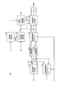
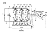
- FIG. 1 is a diagram showing a power train configuration of an electric vehicle according to Embodiment 1 of the present invention.
- electrically powered vehicle 100 includes power storage device B, inverter 10, electronic control unit (hereinafter referred to as “ECU (Electronic Control Unit)”) 20, motor generator MG, and wheels DW. Is provided.
- Electric vehicle 100 further includes a positive line PL, a negative line NL, a capacitor C, a U-phase line UL, a V-phase line VL, and a W-phase line WL.
- Electric vehicle 100 further includes a voltage sensor 22, a current sensor 24, and a rotation angle sensor 26.
- the positive electrode terminal and the negative electrode terminal of power storage device B are connected to positive electrode line PL and negative electrode line NL, respectively.
- Capacitor C is connected between positive electrode line PL and negative electrode line NL.
- Inverter 10 includes a U-phase arm 12, a V-phase arm 14, and a W-phase arm 16.
- U-phase arm 12, V-phase arm 14 and W-phase arm 16 are connected in parallel between positive electrode line PL and negative electrode line NL.
- U-phase arm 12 includes transistors Q1 and Q2 connected in series
- V-phase arm 14 includes transistors Q3 and Q4 connected in series
- W-phase arm 16 includes transistors Q5 and Q5 connected in series. Consists of Q6.
- Diodes D1 to D6 are connected in antiparallel to the transistors Q1 to Q6, respectively.
- an IGBT Insulated Gate Bipolar Transistor
- a switching element such as a power MOSFET (Metal Oxide Semiconductor Field-Effect Transistor) may be used as the transistor.
- Motor generator MG includes a U-phase coil U, a V-phase coil V, and a W-phase coil W as stator coils.
- U-phase coil U, V-phase coil V and W-phase coil W are connected to connection nodes of upper and lower arms in U-phase arm 12, V-phase arm 14 and W-phase arm 16 of inverter 10, respectively.
- wheel DW is connected with the rotating shaft of motor generator MG.
- the power storage device B is a rechargeable DC power source, and is composed of, for example, a secondary battery such as nickel metal hydride or lithium ion.
- the power storage device B supplies DC power to the inverter 10.
- Power storage device B is charged by receiving electric power regenerated by motor generator MG from inverter 10 during braking of the vehicle. Note that a large-capacity capacitor may be used as the power storage device B.
- the capacitor C smoothes the voltage fluctuation between the positive electrode line PL and the negative electrode line NL.
- Voltage sensor 22 detects a voltage across terminals of capacitor C, that is, voltage Vdc of positive line PL with respect to negative line NL, and outputs the detected value to ECU 20.
- Inverter 10 converts the DC voltage received from power storage device B into a three-phase AC voltage based on signal PWMI from ECU 20, and drives motor generator MG. Inverter 10 also converts the three-phase AC voltage generated by motor generator MG upon receipt of rotational force from wheel DW into a DC voltage based on signal PWMI from ECU 20 during braking of the vehicle, and the converted DC voltage. Is output to the power storage device B.
- the motor generator MG is a three-phase AC motor, for example, a three-phase AC synchronous motor in which a permanent magnet is embedded in a rotor.
- Motor generator MG is driven by power by inverter 10 to generate a driving force for driving wheels DW.
- Motor generator MG is regeneratively driven by inverter 10 during regenerative braking of the vehicle, and outputs a three-phase AC voltage generated using the rotational force received from wheel DW to inverter 10.
- the current sensor 24 detects each phase motor current and outputs the detected value to the ECU 20.
- the current sensor 24 detects the current of the V-phase line VL and the W-phase line WL, and the current of the U-phase line UL can be calculated using Kirchhoff's law.
- the rotation angle sensor 26 detects the rotation angle ⁇ of the rotor of the motor generator MG, and outputs the detected value to the ECU 20.
- ECU 20 Based on voltage Vdc from voltage sensor 22, motor current I from current sensor 24, and motor rotation angle ⁇ from rotation angle sensor 26, ECU 20 generates signal PWMI for driving inverter 10 by a method described later. Then, the generated signal PWMI is output to the transistors Q1 to Q6 of the inverter 10.
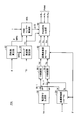
- FIG. 2 is a functional block diagram of the ECU 20 shown in FIG.
- ECU 20 includes a current command generation unit 52, coordinate conversion units 54 and 60, subtraction units 56-1 and 56-2, PI control units 58-1 and 58-2, and a rotational speed.
- a calculation unit 62, a carrier frequency setting unit 64, a PWM center control unit 66, and a PWM signal generation unit 68 are included.
- the current command generator 52 generates a d-axis current command Id * and a q-axis current command Iq * based on the torque command TR of the motor generator MG.
- the coordinate conversion unit 54 converts the motor current I detected by the current sensor 24 into a d-axis current Id and a q-axis current Iq using the motor rotation angle ⁇ from the rotation angle sensor 26.
- Subtraction unit 56-1 subtracts d-axis current Id from d-axis current command Id * and outputs the calculation result to PI control unit 58-1.
- Subtraction unit 56-2 subtracts q-axis current Iq from q-axis current command Iq * and outputs the calculation result to PI control unit 58-2.
- the PI control unit 58-1 performs a proportional integration calculation based on the output of the subtraction unit 56-1, and outputs the calculation result to the coordinate conversion unit 60 as a d-axis voltage command Vd.
- the PI control unit 58-2 performs a proportional integration calculation based on the output of the subtraction unit 56-2, and outputs the calculation result to the coordinate conversion unit 60 as the q-axis voltage command Vq.
- Coordinate transformation unit 60 uses motor rotation angle ⁇ to receive d-axis voltage command Vd and q-axis voltage command Vq received from PI control units 58-1 and 58-2, respectively, as U-phase voltage command Vu and V-phase voltage command Vv. And the W-phase voltage command Vw, and the converted phase voltage command is output to the PWM signal generation unit 68.
- the rotation speed calculation unit 62 calculates the motor rotation number MRN based on the motor rotation angle ⁇ and outputs the calculated value to the carrier frequency setting unit 64.
- Carrier frequency setting unit 64 sets the frequency of the carrier wave (carrier frequency) used when generating the PWM signal based on torque command TR and motor rotation speed MRN of motor generator MG, and is set.
- the carrier frequency FC is output to the PWM center control unit 66 and the PWM signal generation unit 68.
- the PWM center control unit 66 variably controls the center value (hereinafter also referred to as “PWM center”) of each phase modulation wave in the PWM signal generation unit 68 based on the carrier frequency FC and the motor current I by a method described later.
- PWM center correction value ⁇ CE is generated, and the generated PWM center correction value ⁇ CE is output to the PWM signal generation unit 68.
- the PWM signal generation unit 68 generates each phase PWM signal Pu, Pv, Pw based on each phase voltage command Vu, Vv, Vw using the pulse width modulation method, and generates each phase PWM signal Pu, Pv. , Pw are output to the inverter 10 as the signal PWMI. More specifically, the PWM signal generation unit 68 generates each phase modulated wave corresponding to each phase voltage command Vu, Vv, Vw. Further, the PWM signal generation unit 68 generates a carrier wave (carrier) having the carrier frequency FC set by the carrier frequency setting unit 64 by a transmission unit (not shown). The PWM signal generation unit 68 generates each phase PWM signal Pu, Pv, Pw according to the magnitude relationship between each phase modulated wave and a carrier wave.
- the modulated wave is generated so that the center value (PWM center) becomes the center value of the carrier wave.
- the PWM signal generation unit 68 receives the PWM signal from the PWM center control unit 66.
- the PWM center is changed using the PWM center correction value ⁇ CE.
- the PWM signal generation unit 68 changes the PWM center by uniformly adding the PWM center correction value ⁇ CE to each phase modulation wave.
- the PWM signal generation unit 68 compares each phase modulated wave whose PWM center is changed by the PWM center correction value ⁇ CE with the carrier wave, and generates each phase PWM signal Pu, Pv, Pw based on the comparison result.
- the carrier wave is a triangular wave having a frequency of about several kHz to 10 kHz that varies between 0 and 1. Therefore, the median value of the carrier wave is 0.5.
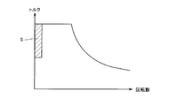
- FIG. 3 is a diagram for explaining the carrier frequency FC set by the carrier frequency setting unit 64 shown in FIG.
- the horizontal axis represents motor rotation speed MRN
- the vertical axis represents torque command TR.
- the carrier frequency FC is set relatively low
- the carrier frequency FC is set relatively high as the motor rotational number MRN increases. Is done.
- the reason why the carrier frequency FC is set low in the low rotation and non-small torque region S is as follows.
- the lower the motor rotation speed the more current flows in a concentrated manner in each phase arm, which is thermally severe.
- the lower the carrier frequency the smaller the switching loss, so the overall loss can be reduced. Therefore, in order to suppress the loss of the inverter according to the motor rotation and torque, it is effective to lower the carrier frequency in the non-small torque region in the low rotation region.
- the reason why the carrier frequency is set high in the high rotation range is to suppress electromagnetic noise accompanying the operation of the switching element.
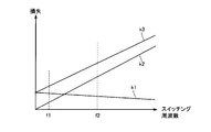
- FIG. 4 is a diagram showing the relationship between the switching frequency and the loss in the inverter.
- the horizontal axis represents the inverter switching frequency (corresponding to the carrier frequency), and the vertical axis represents the loss.
- a line k1 indicates the on-loss that occurs when the switching elements constituting the inverter are on.
- a line k2 indicates a switching loss that occurs when the switching element is turned on / off.
- a line k3 indicates the total loss obtained by adding the ON loss and the switching loss.
- the on loss In the region where the switching frequency is low, the on loss is relatively larger than the switching loss, and the on loss is dominant.
- the switching loss increases as the switching frequency increases, and the switching loss becomes dominant in the region where the switching frequency is medium to high.
- the absolute value of the total loss is smaller than the medium-high frequency region, but the motor rotation speed is low, so it is particularly difficult when the motor lock is very low.
- Thermally severe conditions can occur due to current concentration in the phases. That is, as shown in FIG. 3, in a region where the motor speed is low, the carrier frequency is set low in order to suppress the loss of the inverter. However, depending on the situation (such as when the motor is locked) Concentration causes a severe thermal situation. In the middle and high frequency region where the overall loss is relatively large, the motor rotates, so that the current is dispersed in each phase every short time and is not as severe as the low frequency region in terms of heat.
- the PWM center is variably controlled in a low switching frequency region where on-loss is dominant, thereby avoiding a severe thermal situation. is there.
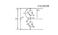
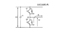
- FIGS. 5 to 7 are diagrams for explaining current and voltage in the inverter.
- FIG. 5 shows the current and voltage when the transistor Q1 of the U-phase upper arm is turned on
- FIG. 6 shows the current and voltage when the transistor Q2 of the U-phase lower arm is turned on.
- FIG. 7 is a waveform diagram of the current and voltage shown in FIGS.
- FIGS. 5 to 7 representatively show a case where current flows from U-phase arm 12 to motor generator MG (the sign of the current in this case is positive). The same applies to the case where a current flows through the arm 12 (when the current is negative) or other phases.
- transistor Q1 in the upper arm is turned on (transistor Q2 in the lower arm is turned off) (from time t2 to t3 and after time t6 in FIG. 7), current Iu is supplied to transistor Q1. Flows, an on-voltage Von1 is applied, and a voltage VH is applied to the lower arm.
- times t1 to t2, t3 to t4, and t5 to t6 are switching periods of the transistors Q1 and Q2.
- the loss ⁇ LQ1 per unit time in the transistor Q1 and the loss ⁇ LD2 per unit time in the diode D2 are expressed by the following equations.
- ⁇ LQ1 2 ⁇ K ⁇ ⁇ (V1 ⁇ Iu) dt + (1 / K ⁇ 2 ⁇ dt) ⁇ K ⁇ ⁇ (Von1 ⁇ Iu) dt
- ⁇ LD2 2 ⁇ K ⁇ ⁇ (V2 ⁇ Iu) dt + (1 / K ⁇ 2 ⁇ dt) ⁇ K ⁇ ⁇ (Von2 ⁇ Iu) dt
- the loss ⁇ LQ1 of the transistor Q1 and the loss ⁇ LD2 of the diode D2 have the same configuration, and their values differ depending on the switching characteristics and the ON voltage.
- the loss is illustrated as shown in FIG. 4 with the switching frequency K as the horizontal axis.
- FIG. 8 is a diagram for explaining an example of the concept of PWM center operation.
- the PWM center is x (0 ⁇ x ⁇ 1)
- the on-duty of transistor Q1 is represented by x.
- the ON loss ⁇ LQ1on of the transistor Q1 and the ON loss ⁇ LD2on of the diode D2 in one cycle are expressed by the following equations.
- FIG. 9 is a diagram showing the relationship between the PWM center and the on-loss.
- line k4 indicates the on-loss ⁇ LQ1on of transistor Q1
- line k5 indicates the on-loss ⁇ LD2on of diode D2.
- a line k6 indicates the sum of the on loss ⁇ LQ1on and the on loss ⁇ LD2on.
- the on-loss ⁇ LQ1on of the transistor Q1 increases.
- FIG. 10 is a diagram showing the relationship between the switching frequency and the inverter loss when the PWM center is operated.
- lines k1 to k3 are as shown in FIG.
- a line k7 indicates the on-loss during the PWM center operation.
- a line k8 indicates the total loss that is the sum of the ON loss and the switching loss during the PWM center operation.
- the loss reduction effect by the PWM center operation is large in the low switching frequency region where the on loss is dominant. In other words, in the region where the switching frequency is medium to high, the effect of reducing the loss by the PWM center operation is small. Therefore, in the first embodiment, a thermally severe situation is avoided by variably controlling the PWM center in a low switching frequency region where on-loss is dominant.
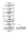
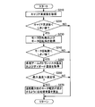
- FIG. 11 is a flowchart for explaining a control structure of the PWM center control unit 66 shown in FIG. The processing shown in this flowchart is called from the main routine and executed at regular time intervals or when a predetermined condition is satisfied.
- PWM center control unit 66 acquires carrier frequency FC from carrier frequency setting unit 64 (step S10). Then, the PWM center control unit 66 determines whether or not the carrier frequency FC is lower than a predetermined threshold value (step S20). This threshold value can be obtained in advance by an offline experiment or the like based on the thermal design of each switching element of the inverter.
- PWM center control unit 66 acquires motor current I (step S30), and the magnitude of the motor current is the maximum. A phase is detected (step S40). Next, the PWM center control unit 66 determines whether or not the motor current of the maximum current phase is a positive value (step S50).
- PWM center control unit 66 determines that the PWM center is smaller than 0.5 (the median value of the carrier wave).
- a correction value ⁇ CE is generated and output to the PWM signal generator 68 (step S60).
- PWM center control unit 66 sets PWM center correction value ⁇ CE so that the PWM center becomes larger than 0.5. Generate and output to the PWM signal generator 68 (step S70).
- FIG. 12 is a diagram showing an example of the change of the PWM center.
- the motor rotation angle ⁇ is 0 ° to 60 °, 120 ° to 180 ° and 240 ° to 300 °, that is, when the motor current of the maximum current phase is a negative value
- the PWM center is larger than 0.5.
- the motor rotation angle ⁇ is 60 ° to 120 °, 180 ° to 240 °, and 300 ° to 360 °, that is, when the motor current of the maximum current phase is a positive value
- the PWM center is smaller than 0.5. To be changed.
- the motor rotation angle ⁇ 1 and the PWM center value C1 shown in FIG. 12 will be described later in the second embodiment.
- the waveform of the PWM center shown in FIG. 12 is an example, and may be discontinuous with respect to a change in the motor rotation angle ⁇ , for example. However, the continuous waveform with respect to the change in the motor rotation angle ⁇ can balance the loss in the inverter 10 among the elements.
- the carrier frequency (switching frequency) of the inverter 10 when the carrier frequency (switching frequency) of the inverter 10 is lower than a predetermined threshold, that is, when the on-loss is a low switching frequency dominant.
- the on-loss of the inverter 10 is reduced by variably controlling the PWM center. Therefore, according to the first embodiment, the loss of inverter 10 can be effectively reduced.
- the power train configuration of the electric vehicle according to the second embodiment is the same as that of the electric vehicle 100 according to the first embodiment shown in FIG.
- FIG. 13 is a functional block diagram of ECU 20A in the second embodiment.
- ECU 20 ⁇ / b> A includes a PWM center control unit 66 ⁇ / b> A instead of PWM center control unit 66 in the configuration of ECU 20 in the first embodiment shown in FIG. 2.
- PWM center control unit 66A receives motor rotation angle ⁇ and motor rotation number MRN from rotation number calculation unit 62, and receives carrier frequency FC from carrier frequency setting unit 64. When the carrier frequency FC is lower than the predetermined threshold value and the motor rotational speed MRN is lower than the predetermined threshold value, the PWM center control unit 66A performs the PWM center by the above method. PWM center correction value ⁇ CE for variably controlling is generated, and the generated PWM center correction value ⁇ CE is output to PWM signal generation unit 68.
- FIG. 14 is a flowchart for explaining the control structure of the PWM center control unit 66A shown in FIG. The processing shown in this flowchart is also called and executed from the main routine at regular time intervals or when a predetermined condition is satisfied.
- this flowchart further includes steps S22 and S24 in the flowchart shown in FIG. That is, when it is determined in step S20 that carrier frequency FC is lower than the threshold value (YES in step S20), PWM center control unit 66A acquires motor rotational speed MRN and motor rotational angle ⁇ (step S22). .
- the PWM center control unit 66A determines whether or not the motor rotational speed MRN is lower than a predetermined threshold value (step S24).
- This threshold value is a value for detecting the motor lock state. Note that the motor lock state can occur, for example, when the forward torque and the vehicle weight are balanced during climbing. If motor rotation speed MRN is lower than the threshold value and a motor lock state is detected in step S24 (YES in step S24), PWM center control unit 66A shifts the process to step S30.
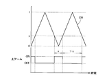
- FIG. 15 is a waveform diagram of a modulated wave when the motor is locked.
- FIG. 15 shows the waveform of the modulated wave when the motor rotation angle when the motor is locked is ⁇ 1 shown in FIG.
- the waveform of the modulated wave when the PWM center is not changed is also shown.
- the triangular wave CR indicates a carrier wave.
- Curves k11 to k13 respectively show a U-phase modulated wave, a V-phase modulated wave, and a W-phase modulated wave when the motor rotation angle when the motor is locked is ⁇ 1.
- the U-phase current of the maximum current phase is a positive value
- the PWM center is changed to C1 smaller than 0.5. Therefore, each phase modulation wave becomes a sine wave centered on C1 smaller than 0.5.
- each phase-modulated wave is a sine wave centered at 0.5 (the median value of the carrier wave).
- the PWM signal is generated so that when the modulated wave is larger than the carrier wave, the upper arm transistor is turned on (the lower arm transistor is turned off), and the PWM center is changed to C1 smaller than 0.5. Then, the on-time of the transistors in the upper arms of each phase is shorter than when the PWM center is not changed (0.5). Therefore, when the motor rotation angle is ⁇ 1, the on-loss of the upper-arm transistor Q1 in the U-phase of the maximum current phase is reduced, and overheating of the U-phase can be prevented.
- the carrier frequency (switching frequency) of inverter 10 is lower than a predetermined threshold value, and motor rotation speed MRN is lower than the predetermined threshold value.
- the PWM center is variably controlled when the temperature is low (when the motor lock state is detected), that is, when a severe heat condition appears conspicuously due to current concentration in a specific phase because the motor rotational speed MRN is low. Therefore, the dominant on-loss is effectively reduced. Therefore, according to this Embodiment 2, it can suppress that an electric current concentrates and flows into a specific element or phase. As a result, the inverter 10 can be prevented from being overheated.
- the overall configuration of the electric vehicle and ECU according to Embodiment 3 is the same as that of electric vehicle 100 shown in FIG. 1 and ECU 20A shown in FIG. Hereinafter, a method for determining the PWM center in the third embodiment will be described.
- the first term on the right side represents switching loss, and the second term on the right side represents on-loss.
- V CE represents the collector-emitter voltage
- I CE represents the current flowing through the transistor Q1.
- V ON1 indicates a collector-emitter voltage (ON voltage) when the transistor Q1 is ON.
- V ON2 indicates the ON voltage of the transistor Q4 (or Q6).
- FIG. 16 is a diagram for explaining the relationship between the PWM center and the on-time of the transistor. Referring to FIG. 16, let the PWM center be x (0 ⁇ x ⁇ 1). When the on-time of the U-phase upper arm transistor Q1 is defined as x, the on-time of the V-phase lower arm transistor Q4 is (1-x). Then, the following equation is derived from the equation (7).
- the on loss of each phase can be balanced while the on loss of the maximum current phase is reduced.
- the overall configuration of the electric vehicle and ECU according to Embodiment 4 is the same as that of electric vehicle 100 shown in FIG. 1 and ECU 20A shown in FIG.
- FIG. 17 is a flowchart for explaining a control structure of the PWM center control unit in the fourth embodiment.
- this flowchart includes steps S65 and S75 in place of steps S60 and S70 in the flowchart shown in FIG. That is, when it is determined in step S50 that the motor current of the maximum current phase is a positive value (YES in step S50), PWM center control unit 66A causes the transistor in the upper arm of the maximum current phase to be always on.
- the PWM center correction value ⁇ CE is generated and output to the PWM signal generation unit 68 (step S65).
- the PWM center control unit 66A sets a value obtained by subtracting the value of the modulation wave of the maximum current phase from the maximum value 1 as the PWM center correction value ⁇ CE. Thereby, the modulation wave of the maximum current phase has the maximum value 1, and the switching of the transistor of the phase stops (the upper arm is always on). Then, two-phase modulation control by other phases is performed.
- step S50 when it is determined in step S50 that the motor current of the maximum current phase is a negative value (NO in step S50), PWM center control unit 66A causes the transistor in the lower arm of the maximum current phase to be always on.
- the PWM center correction value ⁇ CE is generated and output to the PWM signal generation unit 68 (step S75).
- the PWM center control unit 66A sets a value obtained by inverting the sign of the modulation wave of the maximum current phase as the PWM center correction value ⁇ CE.
- the modulation wave of the maximum current phase has the minimum value 0, and the switching of the transistor of the phase stops (the lower arm is always on). Then, two-phase modulation control by other phases is performed.
- FIG. 18 is a diagram showing changes in the PWM center in the fourth embodiment.
- the motor rotation angle ⁇ is 0 ° to 60 °, 120 ° to 180 °, and 240 ° to 300 °, that is, when the motor current of the maximum current phase is a negative value
- the PWM center The maximum phase modulation wave is changed so that the minimum value is zero.
- the motor rotation angle ⁇ is 60 ° to 120 °, 180 ° to 240 °, and 300 ° to 360 °, that is, when the motor current of the maximum current phase is a positive value
- the PWM center is the modulation wave of the maximum current phase. Is changed to a maximum value of 1.
- the motor rotation angle when the motor lock state is detected is ⁇ 1
- the maximum current phase is the U phase
- the U phase motor current Iu is a positive value
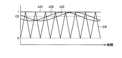
- FIG. 19 is a waveform diagram of a modulated wave when the motor is locked in the fourth embodiment.
- FIG. 19 shows a waveform of a modulated wave when the motor rotation angle when the motor is locked is ⁇ 1 shown in FIG.
- straight line k21 and curves k22 and k23 indicate a U-phase modulated wave, a V-phase modulated wave, and a W-phase modulated wave when the motor rotation angle when the motor is locked is ⁇ 1, respectively.
- the U-phase current of the maximum current phase is a positive value
- the PWM center is changed to C2 so that the U-phase modulated wave has a maximum value of 1. Therefore, switching of the U-phase arm is stopped (the upper-arm transistor is always on), and two-phase modulation control is performed by the V-phase and the W-phase.
- the relative relationship between the phase-modulated waves is maintained, so the interphase voltage that contributes to the torque generated by motor generator MG does not change.
- the switching loss is larger than the on-loss
- the switching of the maximum current phase is stopped, and the two other phases are used. Since the PWM center is changed so that phase modulation control is performed, the switching loss of the maximum current phase is zero. Therefore, according to the fourth embodiment, overheating of inverter 10 at the time of motor lock can be prevented.
- FIG. 20 is a diagram showing a power train configuration of an electric vehicle according to the fifth embodiment.
- electrically powered vehicle 100A further includes temperature sensors 31 to 36 in the configuration of electrically powered vehicle 100 shown in FIG. 1, and includes ECU 20B instead of ECU 20.
- Temperature sensors 31 to 36 detect the temperatures T11 to T16 of the transistors Q1 to Q6, respectively, and output the detected values to the ECU 20B.
- the ECU 20B generates a signal PWMI for driving the inverter 10 based on the voltage Vdc, the motor current I, the motor rotation angle ⁇ , and the temperature T11 to T16, and uses the generated signal PWMI of the inverter 10 by a method described later. Output to transistors Q1-Q6.
- FIG. 21 is a functional block diagram of ECU 20B shown in FIG.
- ECU 20B includes a PWM center control unit 66B instead of PWM center control unit 66A in the configuration of ECU 20A shown in FIG.
- the PWM center control unit 66B generates a PWM center correction value ⁇ CE by a method described later based on the motor rotation angle ⁇ , the motor rotation number MRN, the motor current I, and the temperatures T11 to T16, and the generated PWM center correction value ⁇ CE. Is output to the PWM signal generator 68.
- FIG. 22 is a flowchart for illustrating a control structure of PWM center control unit 66B shown in FIG. Referring to FIG. 22, this flowchart further includes steps S80 to S130 in the flowchart shown in FIG. That is, when the PWM center correction value ⁇ CE is determined in step S60 or S70, the PWM center control unit 66B acquires the temperatures T11 to T16 of the transistors Q1 to Q6 (step S80), and the maximum of the temperatures T11 to T16. It is determined whether or not the object exceeds the specified value (step S90). This prescribed value is determined based on, for example, the heat-resistant temperature of transistors Q1 to Q6.
- step S90 If it is determined that the maximum temperature does not exceed the specified value (NO in step S90), the process proceeds to step S130. On the other hand, when it is determined that the maximum temperature exceeds the specified value (YES in step S90), PWM center control unit 66B determines whether or not the motor current of the phase with the maximum temperature is a positive value (step S100). ).
- PWM center control unit 66B When it is determined that the motor current of the maximum temperature phase is a positive value (YES in step S100), PWM center control unit 66B reduces PWM center correction value ⁇ CE generated in step S60 or S70 in the direction in which the PWM center decreases. (Step S110). On the other hand, when it is determined that the motor current of the maximum temperature phase is a negative value (NO in step S100), PWM center control unit 66B corrects PWM center correction value ⁇ CE in the direction in which the PWM center increases (step S120). ).
- the PWM center control unit 66B outputs the PWM center correction value ⁇ CE to the PWM signal generation unit 68 (step S130).
- the correction amount of the PWM center correction value ⁇ CE in steps S110 and S120 may be a predetermined fixed amount or an amount corresponding to the temperature excess amount from the specified value.
- the PWM center is further corrected based on the temperatures of the transistors Q1 to Q6 of the inverter 10, overheating of the inverter 10 can be reliably prevented.
- FIG. 23 is a diagram showing a power train configuration of an electric vehicle according to the sixth embodiment.
- electrically powered vehicle 100B further includes temperature sensors 41 to 46 in the configuration of electrically powered vehicle 100A according to the fifth embodiment shown in FIG. 20, and includes ECU 20C instead of ECU 20B.
- Temperature sensors 41 to 46 detect the temperatures T21 to T26 of the diodes D1 to D6, respectively, and output the detected values to the ECU 20C.
- the ECU 20C generates a signal PWMI for driving the inverter 10 based on the voltage Vdc, the motor current I, the motor rotation angle ⁇ , and the temperatures T11 to T16 and T21 to T26, and generates the signal PWMI. Is output to the transistors Q1 to Q6 of the inverter 10.
- FIG. 24 is a functional block diagram of ECU 20C shown in FIG.
- ECU 20C includes a PWM center control unit 66C in place of PWM center control unit 66A in the configuration of ECU 20A shown in FIG.
- the PWM center control unit 66C generates a PWM center correction value ⁇ CE by a method described later based on the motor rotation angle ⁇ , the motor rotation number MRN, the motor current I, and the temperatures T11 to T16, T21 to T26, and the generated PWM
- the center correction value ⁇ CE is output to the PWM signal generator 68.
- FIG. 25 is a flowchart for explaining a control structure of the PWM center control unit 66C shown in FIG. Referring to FIG. 25, this flowchart includes steps S85 and S95 instead of steps S80 and S90 in the flowchart shown in FIG. 22, and further includes steps S102 and S104. That is, when the PWM center correction value ⁇ CE is determined in step S60 or S70, the PWM center control unit 66C acquires the temperatures T11 to T16 of the transistors Q1 to Q6 and the temperatures T21 to T26 of the diodes D1 to D6 (step S85). ), It is determined whether or not the maximum of the temperatures T11 to T16 and T21 to T26 exceeds a specified value (step S95).
- step S100 determines whether the motor current of the maximum temperature phase is a positive value (YES in step S100).
- PWM center control unit 66C determines whether the element having the maximum temperature is a transistor or a diode. Determination is made (step S102). If it is determined in step S102 that the element is a transistor (“Tr” in step S102), the PWM center control unit 66C proceeds to step S110. If it is determined in step S102 that the element is a diode (“Di” in step S102), the PWM center control unit 66C proceeds to step S120.
- step S100 determines whether the motor current of the maximum temperature phase is a negative value (NO in step S100).
- PWM center control unit 66C determines whether the element having the maximum temperature is a transistor or a diode. Determination is made (step S104). If it is determined in step S104 that the element is a transistor (“Tr” in step S104), the PWM center control unit 66C proceeds to step S120. If it is determined in step S104 that the element is a diode (“Di” in step S104), the PWM center control unit 66C proceeds to step S110.
- the temperatures of not only the transistors Q1 to Q6 but also the diodes D1 to D6 are taken into account, overheating of the inverter 10 can be further reliably prevented.
- FIG. 26 is a diagram showing a waveform of each phase motor current.
- the horizontal axis indicates the current phase, and this current phase corresponds to the motor rotation angle ⁇ .
- the current phase when the motor lock state is detected is ⁇ 1.
- the current concentrates on the transistor Q1 of the U-phase upper arm and the temperature of the transistor Q1 rises.
- the U-phase motor current Iu decreases.
- the current phase is forcibly changed (for example, to be 0).
- the direction in which the current phase is changed is a direction in which motor generator MG rotates in a rotation direction corresponding to the direction opposite to the traveling direction of the vehicle. This is because the motor cannot be moved in the traveling direction when the motor is locked (for example, when climbing up), so that even if the current phase is changed so that the motor generator MG rotates in the rotational direction corresponding to the traveling direction of the vehicle, the balanced state cannot be entered. Because. On the other hand, when the current phase is changed so that motor generator MG rotates in a rotational direction corresponding to the direction opposite to the traveling direction of the vehicle, the vehicle slides down and shifts to a balanced state.
- the overall configuration of the electric vehicle according to the seventh embodiment is the same as that of the electric vehicle 100B shown in FIG.
- FIG. 27 is a functional block diagram of the ECU according to the seventh embodiment.
- ECU 20D further includes a phase changing unit 70 and an adding unit 72 in the configuration of ECU 20C shown in FIG.
- the phase change unit 70 calculates a phase change amount ⁇ by a method described later based on the motor rotation angle ⁇ , the motor rotation number MRN, and the temperatures T11 to T16, T21 to T26, and adds the calculated phase change amount ⁇ .
- Motor rotation number MRN is received from rotation number calculation unit 62.
- the adding unit 72 adds the phase change amount ⁇ to the motor rotation angle ⁇ detected by the rotation angle sensor 26 and outputs the calculation result to the coordinate conversion units 54 and 60 as the motor rotation angle.
- FIG. 28 is a flowchart for explaining a control structure of phase changing unit 70 shown in FIG.
- phase changing unit 70 determines whether carrier frequency FC is lower than a predetermined threshold value. (Step S220). If it is determined that carrier frequency FC is lower than the threshold value (YES in step S220), phase changing unit 70 acquires motor rotational speed MRN and motor rotational angle ⁇ (step S230), and motor rotational speed MRN is It is determined whether or not the threshold value is lower than a predetermined threshold value (step S240).
- This threshold value is a value for detecting the motor lock state.
- phase changing unit 70 has temperatures T11 to T16 of transistors Q1 to Q6 and temperatures T21 of diodes D1 to D6.
- T26 step S250
- This specified value is determined based on, for example, the heat-resistant temperature of transistors Q1-Q6.
- phase change unit 70 causes motor rotation angle ⁇ at that time to decrease the motor current of the phase with the maximum temperature.
- the phase change amount ⁇ is calculated based on (step S270). Specifically, since the phase at which the motor current is 0 for each phase is known, the motor generator MG rotates in the rotation direction corresponding to the direction opposite to the traveling direction of the vehicle, and the current motor rotation The phase difference between the angle ⁇ and the phase at which the current of the maximum current phase becomes zero is defined as a phase change amount ⁇ .
- the detection result in the PWM center control unit may be used for detecting the motor lock state.
- the seventh embodiment since the current of the maximum temperature phase is reduced, the element temperature of the maximum temperature phase can be reliably reduced.
- the seventh embodiment is effective when the element temperature exceeds the specified value even if the PWM center is changed. Therefore, the temperature specified value in step S260 may be set higher than the temperature specified value in the PWM center control unit.
- Embodiments 2 to 7 described above relate to when the motor is locked.
- the PWM center can be varied for the purpose of reducing the loss of the entire inverter even in the motor speed range where the motor is not locked. Control.
- FIG. 29 is a diagram showing a control range of the PWM center with respect to the motor rotation speed MRN.
- the horizontal axis represents motor rotation speed MRN
- N1 represents the detection threshold value of the motor lock state.
- the PWM center is controlled to a value obtained in advance offline so that the loss of the entire inverter is minimized. That is, a PWM center that minimizes the total loss of the inverter 10 is obtained in advance for each current phase through experiments, and the PWM center is mapped for each motor rotation angle ⁇ . Then, the PWM center is set based on the motor rotation angle ⁇ using the map. For example, the PWM center may show a change as shown in FIG.
- the control range of the PWM center is limited as the motor rotation speed MRN increases. If the motor rotation speed at which the amplitude of the modulated wave is maximum is N2, the PWM center cannot be changed from 0.5 when the motor rotation speed MRN is N2 or more.
- the PWM center is variably controlled within the range of the solid line shown in FIG. That is, when the motor rotation speed MRN is in the range of N1 to N2, the PWM center is set using the map so that the loss of the entire inverter is minimized within the range of the solid line shown in FIG. When the motor rotation speed MRN exceeds N2, the PWM center is fixed at 0.5.
- the overall configuration of the electric vehicle and ECU according to the eighth embodiment is the same as that of electric vehicle 100B shown in FIG. 23 and ECU 20C shown in FIG.
- FIG. 30 is a flowchart for illustrating a control structure of PWM center control unit 66D in the eighth embodiment.
- PWM center control unit 66D acquires carrier frequency FC from carrier frequency setting unit 64 (step S310), it determines whether carrier frequency FC is lower than a predetermined threshold value. (Step S320). If it is determined that carrier frequency FC is lower than the threshold value (YES in step S320), PWM center control unit 66D obtains motor rotation speed MRN and motor rotation angle ⁇ (step S330), and motor rotation speed MRN. Is lower than the threshold value N1 (step S340).
- This threshold value N1 is a value for detecting the motor lock state.
- PWM center control unit 66D When it is determined that motor rotation speed MRN is lower than threshold value N1 (YES in step S340), PWM center control unit 66D generates PWM center correction value ⁇ CE so that a PWM center for overheating suppression is set. (Step S360). Specifically, the PWM center control unit 66D calculates the PWM center correction value ⁇ CE using the method described in each of the above embodiments.
- step S340 If it is determined in step S340 that motor rotational speed MRN is equal to or higher than threshold value N1 (NO in step S340), PWM center control unit 66D has motor rotational speed MRN lower than threshold value N2 (> N1). Is determined (step S350).
- PWM center control unit 66D When it is determined that motor rotational speed MRN is lower than threshold value N2 (YES in step S350), PWM center control unit 66D generates PWM center correction value ⁇ CE so that the PWM center for minimum loss is set. (Step S370). Specifically, the PWM center control unit 66D determines a PWM center for minimum loss based on the motor rotation angle ⁇ using a map obtained in advance, and the PWM center correction value based on the determined PWM center. ⁇ CE is calculated.
- step S350 If it is determined in step S350 that motor rotational speed MRN is equal to or greater than threshold value N2 (NO in step S350), PWM center control unit 66D sets PWM center correction value ⁇ CE so that the PWM center becomes 0.5. It is set to 0 (step S380). Then, the PWM center control unit 66D outputs the PWM center correction value ⁇ CE to the PWM signal generation unit 68 (step S390).
- the PWM center is variably controlled so as to reduce the loss of the entire inverter in the motor rotation speed range ( ⁇ N2) that is not in the motor locked state, the energy cost can be reduced. Can do.
- FIG. 31 is a waveform diagram of a modulated wave.
- curves k31 to k33 indicate phase-modulated waves, and triangular wave CR indicates a carrier wave.
- the PWM center is CE (> 0.5), and at this time, the peak value of each phase modulation wave reaches the upper limit value (1).
- the PWM center correction value ⁇ CE is limited so that the PWM center does not exceed this CE.
- FIG. 32 is a flowchart for illustrating a control structure of PWM center control unit 66E in the ninth embodiment.
- this flowchart further includes steps S400 to S450 in the flowchart shown in FIG. That is, when the PWM center correction value ⁇ CE is calculated in step S360 or S370, each phase modulation wave is recalculated based on the PWM center correction value ⁇ CE (step S400). Then, the maximum peak value and the minimum peak value of the recalculated modulated wave are calculated (step S410).
- the PWM center control unit 66E determines whether or not the maximum peak value of the modulated wave is larger than the predetermined value A (step S420).
- the predetermined value A is the maximum value of the carrier wave, and is 1 in this embodiment.
- step S420 If it is determined in step S420 that the maximum peak value of the modulated wave is larger than the predetermined value A (YES in step S420), the PWM center control unit 66E causes the PWM center to decrease by (maximum peak value ⁇ A). The PWM center correction value ⁇ CE is corrected (step S430). Thereafter, the PWM center control unit 66E shifts the process to step S390.
- PWM center control unit 66E has the minimum peak value of the modulated wave smaller than predetermined value B. Is determined (step S440).
- the predetermined value B is the minimum value of the carrier wave and is 0 in this embodiment.
- step S440 When it is determined in step S440 that the minimum peak value of the modulated wave is smaller than predetermined value B (YES in step S440), PWM center control unit 66E increases the PWM center by (B-minimum peak value). The PWM center correction value ⁇ CE is corrected (step S450). Thereafter, the PWM center control unit 66E shifts the process to step S390.
- step S440 determines whether the minimum peak value of the modulated wave is greater than or equal to predetermined value B (NO in step S440). If it is determined in step S440 that the minimum peak value of the modulated wave is greater than or equal to predetermined value B (NO in step S440), PWM center control unit 66E moves the process to step S390.
- step S380 when the process by step S380 is performed, the PWM center control part 66E will transfer a process to step S390.
- the PWM center is limited in real time so that the modulated wave does not exceed the upper and lower limits.
- the variable region of the PWM center when the variable region of the PWM center is set in advance, the variable region can be narrowed in terms of securing a margin in consideration of variations of various components and sensors.
- the variable area of the PWM center can be made as wide as possible. Therefore, the loss of the inverter can be suppressed to the maximum as long as the motor control does not fail.
- the control in the ECU is actually performed by a CPU (Central Processing Unit), and the CPU reads a program including each step of the above flowchart from a ROM (Read Only Memory). Then, the read program is executed to execute the process according to the above flowchart. Therefore, the ROM corresponds to a computer (CPU) readable recording medium in which a program including each step of the above flowchart is recorded.
- CPU Central Processing Unit
- ROM Read Only Memory
- a boost converter that boosts the voltage from power storage device B and supplies it to inverter 10 may be provided between power storage device B and inverter 10.
- a boost converter for example, a known chopper circuit can be used.
- the present invention can be applied not only to an electric vehicle in which the motor generator MG is mounted as a power source for running the vehicle, but also to a hybrid vehicle in which an internal combustion engine is mounted, and a fuel cell vehicle in which a fuel cell is mounted as a DC power source. .
- motor generator MG corresponds to “AC motor” in the present invention.
- the PWM signal generation unit 68 corresponds to the “signal generation unit” in the present invention, and the PWM center control units 66 and 66A to 66E correspond to the “control unit” in the present invention.
- the current sensor 24 corresponds to the “current detection unit” in the present invention, and the temperature sensors 31 to 36 and 41 to 46 correspond to the “temperature detection unit” in the present invention.
Landscapes
- Engineering & Computer Science (AREA)
- Power Engineering (AREA)
- Transportation (AREA)
- Mechanical Engineering (AREA)
- Electric Propulsion And Braking For Vehicles (AREA)
- Control Of Ac Motors In General (AREA)
- Control Of Motors That Do Not Use Commutators (AREA)
- Inverter Devices (AREA)
Abstract
キャリア周波数設定部(64)は、モータジェネレータのトルク指令(TR)およびモータ回転数(MRN)に基づいてキャリア周波数(FC)を設定する。PWM信号生成部(68)は、各相電圧指令(Vu,Vv,Vw)に対応する各相変調波を生成し、各相変調波とキャリア周波数(FC)を有する搬送波(キャリア)との大小関係に応じて各相PWM信号(Pu,Pv,Pw)を生成する。PWMセンター制御部(66)は、キャリア周波数(FC)が予め定められた周波数よりも低いとき、PWMセンターを可変制御するためのPWMセンター補正値(ΔCE)を生成してPWM信号生成部(68)へ出力する。
Description
この発明は、車両走行用の動力源として交流モータを搭載する電動車両の制御技術に関する。
近年、環境問題を背景に、電気自動車(Electric Vehicle)やハイブリッド車両(Hybrid Vehicle)、燃料電池車(Fuel Cell Vehicle)などの電動車両が注目されている。これらの電動車両の多くは、車両走行用の動力源として、インバータによって駆動される交流モータを搭載する。
このような電動車両においては、たとえば登坂時に駆動トルクと車重とが釣り合っていわゆる「モータロック状態」(モータトルクを出力しつつモータ回転数が極めて低い状態)になると、特定の相に電流が集中して流れることによりインバータの損失が増大し、インバータが短時間で過熱し得る。
そこで、特開平2002-272125号公報(特許文献1)は、交流電圧基準の周波数が所定値以下のとき、電力変換器を構成するスイッチング素子の損失を低減可能な制御装置を開示する。この制御装置は、電力変換器を構成する電力半導体素子をPWM(Pulse Width Modulation)制御する。そして、制御装置は、交流電圧基準の周波数が所定値以下のとき、交流電圧基準に直流オフセット電圧を加えて、電力半導体素子の損失を低減させる。
この制御装置によれば、交流低周波通電時の電力半導体素子の損失を低減することが可能となる(特許文献1参照)。
特開平2002-272125号公報
特開平9-191508号公報
特開2000-102257号公報
特開平6-245577号公報
特開2004-48885号公報
特開2003-204028号公報
インバータの損失は、スイッチング素子がオン/オフする際に発生するスイッチング損失と、スイッチング素子がオンしているときに発生するオン損失とからなる。しかしながら、上記特開平2002-272125号公報に開示される手法は、スイッチング素子のオン損失のみに着目したものであり、スイッチング損失も併せたトータルの損失を考慮した場合、必ずしも効果的でない可能性がある。
それゆえに、この発明の目的は、インバータの損失を効果的に低減可能な電動車両の制御装置およびそれを備えた電動車両を提供することである。
また、この発明の別の目的は、インバータの損失を効果的に低減可能な電動車両の制御方法およびその制御方法をコンピュータに実行させるためのプログラムを記録したコンピュータ読取可能な記録媒体を提供することである。
この発明によれば、電動車両の制御装置は、車両走行用の動力源として交流モータを搭載する電動車両の制御装置であって、インバータと、信号生成部と、制御部とを備える。インバータは、交流モータを駆動する。信号生成部は、パルス幅変調法に基づいて、インバータのスイッチング素子をオン/オフするための信号を生成する。制御部は、インバータのスイッチング周波数が予め定められた周波数よりも低いとき、信号生成部において用いられる変調波の中心値を可変制御することによってインバータの損失を低減可能に構成される。
好ましくは、予め定められた周波数は、インバータのスイッチング損失に対してインバータのオン損失が相対的に大きくなるスイッチング周波数の領域に基づいて設定される。
好ましくは、制御部は、インバータのスイッチング周波数が予め定められた周波数よりも低く、かつ、交流モータの回転数が予め定められた回転数よりも低いとき、変調波の中心値を可変制御することによってインバータにおける電流集中を抑止可能に構成される。
さらに好ましくは、電動車両の制御装置は、電流検出部をさらに備える。電流検出部は、交流モータの各相電流を検出する。制御部は、電流が最大の相においてインバータから交流モータへ電流が流れているとき、信号生成部において用いられる搬送波の中央値よりも小さくなるように変調波の中心値を変更する。また、制御部は、電流最大の相において交流モータからインバータへ電流が流れているとき、搬送波の中央値よりも大きくなるように変調波の中心値を変更する。
さらに好ましくは、制御部は、インバータの各相におけるオン損失が均衡するように予め求められた値に変調波の中心値を変更する。
好ましくは、制御部は、電流が最大の相の変調波が所定の最大値または最小値となることによってその電流最大の相のスイッチング動作が停止してその他の相による変調制御が行なわれるように、変調波の中心値を変更する。
好ましくは、電動車両の制御装置は、温度検出部をさらに備える。温度検出部は、インバータの素子温度を検出する。制御部は、素子温度が最大の相においてインバータから交流モータへ電流が流れているとき、信号生成部において用いられる搬送波の中央値よりも小さくなるように変調波の中心値を変更する。また、制御部は、温度最大の相において交流モータからインバータへ電流が流れているとき、搬送波の中央値よりも大きくなるように変調波の中心値を変更する。
好ましくは、電動車両の制御装置は、温度検出部と、位相変更部とをさらに備える。温度検出部は、インバータの素子温度を検出する。位相変更部は、素子温度が最大の相に流れる電流値が減少するように変調波の位相を変更する。
さらに好ましくは、位相変更部は、電流値が略零となるように変調波の位相を変更する。
好ましくは、制御部は、交流モータの回転数が予め定められた回転数以上のとき、インバータの全体の損失が最小となるように変調波の位相ごとに予め求められた値に変調波の中心値を可変制御する。
さらに好ましくは、制御部は、変調波の中心値を変更したことにより変調波のピークが搬送波のピークを超えた場合、変調波のピークが搬送波のピークよりも小さくなるように変調波の中心値を補正する。
また、この発明によれば、電動車両は、車両の駆動力を発生する交流モータと、交流モータの出力軸に連結される車輪と、上述したいずれかの制御装置とを備える。
また、この発明によれば、電動車両の制御方法は、車両走行用の動力源として交流モータを搭載する電動車両の制御方法であって、第1および第2のステップを備える。第1のステップでは、パルス幅変調法に基づいて、交流モータを駆動するインバータのスイッチング素子をオン/オフするための信号が生成される。第2のステップでは、インバータのスイッチング周波数が予め定められた周波数よりも低いとき、信号の生成に用いる変調波の中心値を可変制御することによってインバータの損失が低減される。
好ましくは、予め定められた周波数は、インバータのスイッチング損失に対してインバータのオン損失が相対的に大きくなるスイッチング周波数の領域に基づいて設定される。
好ましくは、第2のステップにおいて、インバータのスイッチング周波数が予め定められた周波数よりも低く、かつ、交流モータの回転数が予め定められた回転数よりも低いとき、変調波の中心値を可変制御することによってインバータにおける電流集中が抑止される。
さらに好ましくは、第2のステップにおいて、電流が最大の相においてインバータから交流モータへ電流が流れているとき、信号の生成に用いる搬送波の中央値よりも小さくなるように変調波の中心値が変更される。また、電流最大の相において交流モータからインバータへ電流が流れているときは、搬送波の中央値よりも大きくなるように変調波の中心値が変更される。
さらに好ましくは、第2のステップにおいて、インバータの各相におけるオン損失が均衡するように予め求められた値に変調波の中心値が変更される。
好ましくは、第2のステップにおいて、電流が最大の相の変調波が所定の最大値または最小値となることによってその電流最大の相のスイッチング動作が停止してその他の相による変調制御が行なわれるように、変調波の中心値が変更される。
好ましくは、第2のステップにおいて、インバータの素子温度が最大の相においてインバータから交流モータへ電流が流れているとき、信号の生成に用いる搬送波の中央値よりも小さくなるように変調波の中心値が変更される。また、温度最大の相において交流モータからインバータへ電流が流れているときは、搬送波の中央値よりも大きくなるように変調波の中心値が変更される。
好ましくは、電動車両の制御方法は、第3のステップをさらに備える。第3のステップでは、インバータの素子温度が最大の相に流れる電流値が減少するように変調波の位相が変更される。
好ましくは、第3のステップにおいて、電流値が略零となるように変調波の位相が変更される。
好ましくは、電動車両の制御方法は、第4のステップをさらに備える。第4のステップでは、交流モータの回転数が予め定められた回転数以上のとき、インバータの全体の損失が最小となるように変調波の位相ごとに予め求められた値に変調波の中心値が可変制御される。
さらに好ましくは、電動車両の制御方法は、第5および第6のステップをさらに備える。第5のステップでは、変調波の中心値を変更したことにより変調波のピークが搬送波のピークを超えたか否かが判定される。第6のステップでは、変調波のピークが搬送波のピークを超えたと判定された場合、変調波のピークが搬送波のピークよりも小さくなるように変調波の中心値が補正される。
また、この発明によれば、記録媒体は、コンピュータ読取可能な記録媒体であって、上述したいずれかの電動車両の制御方法をコンピュータに実行させるためのプログラムを記録する。
この発明においては、インバータは、パルス幅変調法に基づいてPWM制御される。ここで、インバータの損失はスイッチング損失とオン損失とからなり、インバータのスイッチング周波数が低いときはオン損失が支配的となり、スイッチング周波数が高くなるに従ってスイッチング損失の割合が増大するところ、この発明においては、インバータのスイッチング周波数が予め定められた周波数よりも低いとき、すなわち、オン損失が支配的となる低スイッチング周波数のとき、信号生成部において用いられる変調波の中心値を可変制御することによってインバータのオン損失を低減する。したがって、この発明によれば、インバータの損失を効果的に低減することができる。
また、この発明においては、インバータのスイッチング周波数が予め定められた周波数よりも低く、かつ、交流モータの回転数が予め定められた回転数よりも低いとき(モータロック状態検出時)、すなわち、スイッチング損失が小さいことによりインバータのトータルの損失はそれ程大きくはないけれどもモータ回転数が低いために特定の相に電流が集中することによって熱的に厳しい状況のとき、変調波の中心値を可変制御することによってオン損失を低減し、インバータにおける電流集中を抑止する。したがって、この発明によれば、特定の素子または相に電流が集中して流れるのを抑止することができる。その結果、インバータが過熱損傷するのを防止することができる。
10 インバータ、12 U相アーム、14 V相アーム、16 W相アーム、20,20A~20D ECU、22 電圧センサ、24 電流センサ、26 回転角センサ、31~36,41~46 温度センサ、52 電流指令生成部、54,60 座標変換部、56-1,56-2 減算部、58-1,58-2 PI制御部、62 回転数算出部、64 キャリア周波数設定部、66,66A~66E PWMセンター制御部、68 PWM信号生成部、70 位相変更部、72 加算部、100,100A,100B 電動車両、B 蓄電装置、PL 正極線、NL 負極線、C コンデンサ、Q1~Q6 トランジスタ、D1~D6 ダイオード、UL U相ライン、VL V相ライン、WL W相ライン、MG モータジェネレータ、DW 車輪。
以下、本発明の実施の形態について、図面を参照しながら詳細に説明する。なお、図中同一または相当部分には同一符号を付してその説明は繰返さない。
[実施の形態1]
図1は、この発明の実施の形態1による電動車両のパワートレーン構成を示した図である。図1を参照して、この電動車両100は、蓄電装置Bと、インバータ10と、電子制御ユニット(以下「ECU(Electronic Control Unit)」と称する。)20と、モータジェネレータMGと、車輪DWとを備える。また、電動車両100は、正極線PLと、負極線NLと、コンデンサCと、U相ラインULと、V相ラインVLと、W相ラインWLとをさらに備える。さらに、電動車両100は、電圧センサ22と、電流センサ24と、回転角センサ26とをさらに備える。
図1は、この発明の実施の形態1による電動車両のパワートレーン構成を示した図である。図1を参照して、この電動車両100は、蓄電装置Bと、インバータ10と、電子制御ユニット(以下「ECU(Electronic Control Unit)」と称する。)20と、モータジェネレータMGと、車輪DWとを備える。また、電動車両100は、正極線PLと、負極線NLと、コンデンサCと、U相ラインULと、V相ラインVLと、W相ラインWLとをさらに備える。さらに、電動車両100は、電圧センサ22と、電流センサ24と、回転角センサ26とをさらに備える。
蓄電装置Bの正極端子および負極端子は、それぞれ正極線PLおよび負極線NLに接続される。コンデンサCは、正極線PLと負極線NLとの間に接続される。インバータ10は、U相アーム12、V相アーム14およびW相アーム16を含む。U相アーム12、V相アーム14およびW相アーム16は、正極線PLと負極線NLとの間に並列に接続される。U相アーム12は、直列に接続されたトランジスタQ1,Q2から成り、V相アーム14は、直列に接続されたトランジスタQ3,Q4から成り、W相アーム16は、直列に接続されたトランジスタQ5,Q6から成る。トランジスタQ1~Q6には、それぞれダイオードD1~D6が逆並列に接続される。
なお、上記のトランジスタとして、たとえばIGBT(Insulated Gate Bipolar Transistor)を用いることができる。また、上記のトランジスタとして、パワーMOSFET(Metal Oxide Semiconductor Field-Effect Transistor)等のスイッチング素子を用いてもよい。
モータジェネレータMGは、U相コイルU、V相コイルVおよびW相コイルWをステータコイルとして含む。U相コイルU、V相コイルVおよびW相コイルWは、インバータ10のU相アーム12、V相アーム14およびW相アーム16における上下アームの接続ノードにそれぞれ接続される。そして、モータジェネレータMGの回転軸に車輪DWが連結される。
蓄電装置Bは、再充電可能な直流電源であり、たとえば、ニッケル水素やリチウムイオン等の二次電池から成る。蓄電装置Bは、直流電力をインバータ10へ供給する。また、蓄電装置Bは、車両の制動時にモータジェネレータMGによって回生発電される電力をインバータ10から受けて充電される。なお、蓄電装置Bとして、大容量のキャパシタを用いてもよい。
コンデンサCは、正極線PLと負極線NLとの間の電圧変動を平滑化する。電圧センサ22は、コンデンサCの端子間電圧、すなわち負極線NLに対する正極線PLの電圧Vdcを検出し、その検出値をECU20へ出力する。
インバータ10は、ECU20からの信号PWMIに基づいて、蓄電装置Bから受ける直流電圧を3相交流電圧に変換し、モータジェネレータMGを駆動する。また、インバータ10は、車両の制動時、車輪DWからの回転力を受けてモータジェネレータMGが発電した3相交流電圧をECU20からの信号PWMIに基づいて直流電圧に変換し、その変換した直流電圧を蓄電装置Bへ出力する。
モータジェネレータMGは、三相交流電動機であり、たとえば、ロータに永久磁石が埋設された三相交流同期電動機から成る。モータジェネレータMGは、インバータ10によって力行駆動され、車輪DWを駆動するための駆動力を発生する。また、モータジェネレータMGは、車両の回生制動時、インバータ10によって回生駆動され、車輪DWから受ける回転力を用いて発電した三相交流電圧をインバータ10へ出力する。
電流センサ24は、各相モータ電流を検出し、その検出値をECU20へ出力する。なお、図1では、電流センサ24は、V相ラインVLおよびW相ラインWLの電流を検出し、U相ラインULの電流は、キルヒホッフの法則を用いて算出できる。回転角センサ26は、モータジェネレータMGのロータの回転角θを検出し、その検出値をECU20へ出力する。
ECU20は、電圧センサ22からの電圧Vdc、電流センサ24からのモータ電流Iおよび回転角センサ26からのモータ回転角θに基づいて、後述の方法により、インバータ10を駆動するための信号PWMIを生成し、その生成した信号PWMIをインバータ10のトランジスタQ1~Q6へ出力する。
図2は、図1に示したECU20の機能ブロック図である。図2を参照して、ECU20は、電流指令生成部52と、座標変換部54,60と、減算部56-1,56-2と、PI制御部58-1,58-2と、回転数算出部62と、キャリア周波数設定部64と、PWMセンター制御部66と、PWM信号生成部68とを含む。
電流指令生成部52は、モータジェネレータMGのトルク指令TRに基づいてd軸電流指令Id*およびq軸電流指令Iq*を生成する。座標変換部54は、回転角センサ26からのモータ回転角θを用いて、電流センサ24によって検出されたモータ電流Iをd軸電流Idおよびq軸電流Iqに変換する。減算部56-1は、d軸電流指令Id*からd軸電流Idを減算し、その演算結果をPI制御部58-1へ出力する。減算部56-2は、q軸電流指令Iq*からq軸電流Iqを減算し、その演算結果をPI制御部58-2へ出力する。
PI制御部58-1は、減算部56-1の出力に基づいて比例積分演算を行ない、その演算結果をd軸電圧指令Vdとして座標変換部60へ出力する。PI制御部58-2は、減算部56-2の出力に基づいて比例積分演算を行ない、その演算結果をq軸電圧指令Vqとして座標変換部60へ出力する。
座標変換部60は、モータ回転角θを用いて、PI制御部58-1,58-2からそれぞれ受けるd軸電圧指令Vdおよびq軸電圧指令VqをU相電圧指令Vu、V相電圧指令VvおよびW相電圧指令Vwに変換し、その変換した各相電圧指令をPWM信号生成部68へ出力する。
回転数算出部62は、モータ回転角θに基づいてモータ回転数MRNを算出し、その算出値をキャリア周波数設定部64へ出力する。
キャリア周波数設定部64は、モータジェネレータMGのトルク指令TRおよびモータ回転数MRNに基づいて、PWM信号を生成する際に用いられる搬送波(キャリア)の周波数(キャリア周波数FC)を設定し、その設定されたキャリア周波数FCをPWMセンター制御部66およびPWM信号生成部68へ出力する。
PWMセンター制御部66は、キャリア周波数FCおよびモータ電流Iに基づいて、後述の方法により、PWM信号生成部68における各相変調波の中心値(以下「PWMセンター」とも称する。)を可変制御するためのPWMセンター補正値ΔCEを生成し、その生成したPWMセンター補正値ΔCEをPWM信号生成部68へ出力する。
PWM信号生成部68は、パルス幅変調法を用いて、各相電圧指令Vu,Vv,Vwに基づいて各相PWM信号Pu,Pv,Pwを生成し、その生成した各相PWM信号Pu,Pv,Pwを信号PWMIとしてインバータ10へ出力する。より具体的には、PWM信号生成部68は、各相電圧指令Vu,Vv,Vwに対応する各相変調波を生成する。また、PWM信号生成部68は、キャリア周波数設定部64によって設定されたキャリア周波数FCを有する搬送波(キャリア)を図示されない発信部により生成する。そして、PWM信号生成部68は、各相変調波と搬送波(キャリア)との大小関係に応じて各相PWM信号Pu,Pv,Pwを生成する。
ここで、一般的なPWM制御においては、変調波は、その中心値(PWMセンター)が搬送波の中央値になるように生成されるところ、PWM信号生成部68は、PWMセンター制御部66からのPWMセンター補正値ΔCEを用いてPWMセンターを変更する。具体的には、PWM信号生成部68は、PWMセンター補正値ΔCEを各相変調波に一律に加算することによってPWMセンターを変更する。そして、PWM信号生成部68は、PWMセンター補正値ΔCEによってPWMセンターが変更された各相変調波を搬送波と比較し、その比較結果に基づいて各相PWM信号Pu,Pv,Pwを生成する。
なお、以下では、搬送波は、0,1の間で変動する、数kHzから10kHz程度の周波数を有する三角波とする。したがって、搬送波の中央値は0.5である。
図3は、図2に示したキャリア周波数設定部64によって設定されるキャリア周波数FCを説明するための図である。図3を参照して、横軸はモータ回転数MRNを示し、縦軸はトルク指令TRを示す。モータ回転数MRNが低く、かつ、トルク指令TRが小さくない領域(領域S)では、キャリア周波数FCは相対的に低く設定され、モータ回転数MRNが高くなるに従ってキャリア周波数FCは相対的に高く設定される。
低回転かつ非小トルクの領域Sにおいてキャリア周波数FCが低く設定されるのは以下の理由による。トルクが大きいほど電流は大きいのでスイッチング素子のオン損失が大きくなり、大トルク領域ではインバータの損失は増大する。また、モータ回転数が低いほど各相アームに集中して流れる電流量が多くなるので熱的に厳しくなる。一方、キャリア周波数が低いほどスイッチング損失は小さいので全体の損失を低減できる。そこで、モータ回転とトルクとに応じてインバータの損失を抑えるためには、低回転域における非小トルク領域のキャリア周波数を下げることが有効である。なお、高回転域でキャリア周波数を高く設定するのは、スイッチング素子の動作に伴なう電磁音を抑制するためである。
図4は、スイッチング周波数とインバータにおける損失との関係を示した図である。図4を参照して、横軸はインバータのスイッチング周波数(キャリア周波数に相当する。)を示し、縦軸は損失を示す。線k1は、インバータを構成するスイッチング素子がオンしているときに発生するオン損失を示す。線k2は、スイッチング素子がオン/オフする際に発生するスイッチング損失を示す。線k3は、オン損失とスイッチング損失とを合計した全体損失を示す。
スイッチング周波数が低周波数の領域では、オン損失の方がスイッチング損失よりも相対的に大きく、オン損失が支配的となる。そして、スイッチング周波数が高くなるに従ってスイッチング損失は増大し、スイッチング周波数が中高周波数の領域では、スイッチング損失が支配的となる。
ここで、オン損失が支配的となる低周波数領域では、全体損失の絶対値としては中高周波領域より小さいけれども、モータの回転数が低いので、特に回転数が極めて低いモータロック時などは特定の相に電流が集中することにより熱的に厳しい状況が発生し得る。すなわち、図3に示したように、モータ回転数が低い領域では、インバータの損失を抑えるためにキャリア周波数は低く設定されるところ、それでも状況によっては(モータロック時など)特定の相に電流が集中することにより熱的に厳しい状況が発生する。なお、全体損失が相対的に大きい中高周波領域では、モータが回転しているので、電流は短時間ごとに各相に分散し、熱的には低周波数領域ほど厳しくはない。
そこで、この実施の形態1では、以下に説明するように、オン損失が支配的な低スイッチング周波数領域において、PWMセンターを可変制御することにより、熱的に厳しい状況を回避することとしたものである。
以下、PWMセンターを操作することによる損失低減の原理について説明する。
図5~図7は、インバータにおける電流および電圧を説明するための図である。図5は、U相上アームのトランジスタQ1がオンしているときの電流および電圧を示し、図6は、U相下アームのトランジスタQ2がオンしているときの電流および電圧を示す。図7は、図5,図6に示した電流および電圧の波形図である。なお、この図5~図7では、U相アーム12からモータジェネレータMGへ電流が流れる場合(この場合の電流の符号を正とする。)について代表的に示されるが、モータジェネレータMGからU相アーム12へ電流が流れる場合(電流が負の場合)や他の相の場合においても同様に考えることができる。
図5~図7は、インバータにおける電流および電圧を説明するための図である。図5は、U相上アームのトランジスタQ1がオンしているときの電流および電圧を示し、図6は、U相下アームのトランジスタQ2がオンしているときの電流および電圧を示す。図7は、図5,図6に示した電流および電圧の波形図である。なお、この図5~図7では、U相アーム12からモータジェネレータMGへ電流が流れる場合(この場合の電流の符号を正とする。)について代表的に示されるが、モータジェネレータMGからU相アーム12へ電流が流れる場合(電流が負の場合)や他の相の場合においても同様に考えることができる。
図5~図7を参照して、上アームのトランジスタQ1がオン(下アームのトランジスタQ2はオフ)しているとき(図7の時刻t2~t3および時刻t6以降)、トランジスタQ1には電流Iuが流れるとともにオン電圧Von1がかかり、下アームには電圧VHがかかる。
また、下アームのトランジスタQ2がオン(上アームのトランジスタQ1はオフ)しているとき(図7の時刻t1以前および時刻t4~t5)、下アームのダイオードD2には電流Iuが流れるとともにオン電圧Von2がかかり、上アームには電圧VHがかかる。
なお、時刻t1~t2,t3~t4,t5~t6は、トランジスタQ1,Q2のスイッチング期間である。
ここで、スイッチング周波数をK(Hz)とすると、トランジスタQ1における単位時間当たりの損失ΔLQ1およびダイオードD2における単位時間当たりの損失ΔLD2は、次式にて表される。
ΔLQ1=2×K×∫(V1×Iu)dt+(1/K-2×dt)×K×∫(Von1×Iu)dt …(1)
ΔLD2=2×K×∫(V2×Iu)dt+(1/K-2×dt)×K×∫(Von2×Iu)dt …(2)
ここで、(1),(2)式の各々の右辺第1項はスイッチング損失を表し、右辺第2項はオン損失を表す。
ΔLD2=2×K×∫(V2×Iu)dt+(1/K-2×dt)×K×∫(Von2×Iu)dt …(2)
ここで、(1),(2)式の各々の右辺第1項はスイッチング損失を表し、右辺第2項はオン損失を表す。
(1),(2)式から分かるように、トランジスタQ1の損失ΔLQ1とダイオードD2の損失ΔLD2とは、式の構成は同じであり、スイッチング特性およびオン電圧によってその値が異なる。なお、(1),(2)式の各々についてスイッチング周波数Kを横軸にして損失を図示すると図4のようになる。
図8は、PWMセンター操作の考え方の一例を説明するための図である。図8を参照して、PWMセンターをx(0≦x≦1)とすると、トランジスタQ1のオンデューティーはxで表される。ここで、1サイクルにおけるトランジスタQ1のオン損失ΔLQ1onおよびダイオードD2のオン損失ΔLD2onは、次式で表される。
ΔLQ1on=Von1×Iu×x …(3)
ΔLD2on=Von2×Iu×(1-x) …(4)
図9は、PWMセンターとオン損失との関係を示した図である。図9を参照して、線k4は、トランジスタQ1のオン損失ΔLQ1onを示し、線k5は、ダイオードD2のオン損失ΔLD2onを示す。線k6は、オン損失ΔLQ1onとオン損失ΔLD2onとの合計を示す。
ΔLD2on=Von2×Iu×(1-x) …(4)
図9は、PWMセンターとオン損失との関係を示した図である。図9を参照して、線k4は、トランジスタQ1のオン損失ΔLQ1onを示し、線k5は、ダイオードD2のオン損失ΔLD2onを示す。線k6は、オン損失ΔLQ1onとオン損失ΔLD2onとの合計を示す。
PWMセンターが大きくなると、トランジスタQ1のオン損失ΔLQ1onが増大し、PWMセンターが最大値1のとき、オン損失ΔLQ1onは最大値ΔLQ1on_max(=Von1×Iu)になる。一方、PWMセンターが小さくなると、ダイオードD2のオン損失ΔLD2onが増大し、PWMセンターが最小値0のとき、オン損失ΔLD2onは最大値ΔLD2on_max(=Von2×Iu)になる。
ここで、トランジスタQ1のオン電圧Von1とダイオードD2のオン電圧Von2との比が仮に2:1であるとした場合、トランジスタQ1のオン損失ΔLQ1onとダイオードD2のオン損失ΔLD2onとが等しいとすると、(3),(4)式よりx=0.33が得られる。したがって、トランジスタQ1のオン電圧Von1とダイオードD2のオン電圧Von2との比が2:1の場合、PWMセンターを0.5(中心値)から0.33にシフトすることによって、トランジスタQ1とダイオードD2との発熱を均衡化することができ、熱的に厳しいトランジスタQ1が過熱するのを防止することができる。
図10は、PWMセンター操作時のスイッチング周波数とインバータ損失との関係を示した図である。図10を参照して、線k1~k3は、図4に示したとおりである。線k7は、PWMセンター操作時のオン損失を示す。線k8は、PWMセンター操作時のオン損失とスイッチング損失とを合計した全体損失を示す。
図10から分かるように、オン損失が支配的となる低スイッチング周波数領域において、PWMセンター操作による損失低減の効果が大きい。言い換えると、スイッチング周波数が中高周波数の領域では、PWMセンター操作による損失低減の効果は小さい。したがって、この実施の形態1では、オン損失が支配的となる低スイッチング周波数領域において、PWMセンターを可変制御することにより、熱的に厳しい状況を回避することとしたものである。
なお、上記においては、U相アーム12からモータジェネレータMGへ電流が流れる場合(電流が正の場合)について説明したが、モータジェネレータMGからU相アーム12へ電流が流れる場合(電流が負の場合)についても同様に考えることができる。すなわち、この場合は、下アームのトランジスタQ2がオンしているとき、トランジスタQ2に電流Iu(負)が流れ、上アームのトランジスタQ1がオンしているとき、ダイオードD1に電流Iu(負)が流れる。そして、トランジスタQ2のオン電圧とダイオードD1のオン電圧との比が仮に2:1であるとした場合、PWMセンターx=0.67が得られる。したがって、モータジェネレータMGからU相アーム12へ電流が流れている場合は、PWMセンターを0.5(中心値)から0.67にシフトすることによって、トランジスタQ2とダイオードD1との発熱を均衡化することができ、熱的に厳しいトランジスタQ2が過熱するのを防止することができる。
図11は、図2に示したPWMセンター制御部66の制御構造を説明するためのフローチャートである。なお、このフローチャートに示される処理は、一定時間ごとまたは所定の条件成立時にメインルーチンから呼出されて実行される。
図11を参照して、PWMセンター制御部66は、キャリア周波数設定部64からキャリア周波数FCを取得する(ステップS10)。そして、PWMセンター制御部66は、そのキャリア周波数FCが予め定められたしきい値よりも低いか否かを判定する(ステップS20)。なお、このしきい値は、インバータの各スイッチング素子の熱設計に基づいて、オフライン実験などで予め求めておくことができる。
そして、キャリア周波数FCがしきい値よりも低いと判定されると(ステップS20においてYES)、PWMセンター制御部66は、モータ電流Iを取得し(ステップS30)、モータ電流の大きさが最大の相を検出する(ステップS40)。次いで、PWMセンター制御部66は、その電流最大相のモータ電流が正値か否かを判定する(ステップS50)。
電流最大相のモータ電流が正値であると判定されると(ステップS50においてYES)、PWMセンター制御部66は、PWMセンターが0.5(搬送波の中央値)よりも小さくなるようにPWMセンター補正値ΔCEを生成してPWM信号生成部68へ出力する(ステップS60)。
一方、電流最大相のモータ電流が負値であると判定されると(ステップS50においてNO)、PWMセンター制御部66は、PWMセンターが0.5よりも大きくなるようにPWMセンター補正値ΔCEを生成してPWM信号生成部68へ出力する(ステップS70)。
図12は、PWMセンターの変化の一例を示した図である。図12を参照して、横軸は、モータ回転角θを示し、U相モータ電流Iuが0となるときθ=0°とする。モータ回転角θが0°~60°、120°~180°および240°~300°のとき、すなわち電流最大相のモータ電流が負値のとき、PWMセンターは、0.5よりも大きくなるように変更される。一方、モータ回転角θが60°~120°、180°~240°および300°~360°のとき、すなわち電流最大相のモータ電流が正値のとき、PWMセンターは、0.5よりも小さくなるように変更される。
なお、この図12に示されるモータ回転角θ1およびPWMセンター値C1については、後ほど実施の形態2において説明する。
なお、この図12に示したPWMセンターの波形は一例であり、たとえばモータ回転角θの変化に対して非連続であってもよい。但し、モータ回転角θの変化に対して連続的な波形のほうが、インバータ10における損失を素子間でバランスさせることができる。
なお、PWMセンターを変更しても、各相変調波の相対的な関係は維持されるので、モータジェネレータMGの発生トルクに寄与する相間電圧は変化しない。
以上のように、この実施の形態1においては、インバータ10のキャリア周波数(スイッチング周波数)が予め定められたしきい値よりも低いとき、すなわち、オン損失が支配的となる低スイッチング周波数のとき、PWMセンターを可変制御することによってインバータ10のオン損失を低減する。したがって、この実施の形態1によれば、インバータ10の損失を効果的に低減することができる。
[実施の形態2]
上述したように、モータ回転数が極めて低いモータロック状態時は、特定の相に電流が集中することによって熱的に厳しい状況が顕著に発生する。そこで、この実施の形態2では、インバータのスイッチング周波数が低く、かつ、モータロック状態が検出されているときにPWMセンターの可変制御が実行される。
上述したように、モータ回転数が極めて低いモータロック状態時は、特定の相に電流が集中することによって熱的に厳しい状況が顕著に発生する。そこで、この実施の形態2では、インバータのスイッチング周波数が低く、かつ、モータロック状態が検出されているときにPWMセンターの可変制御が実行される。
この実施の形態2による電動車両のパワートレーン構成は、図1に示した実施の形態1による電動車両100と同じである。
図13は、実施の形態2におけるECU20Aの機能ブロック図である。図13を参照して、ECU20Aは、図2に示した実施の形態1におけるECU20の構成において、PWMセンター制御部66に代えてPWMセンター制御部66Aを含む。
PWMセンター制御部66Aは、回転数算出部62からモータ回転角θおよびモータ回転数MRNを受け、キャリア周波数設定部64からキャリア周波数FCを受ける。そして、PWMセンター制御部66Aは、キャリア周波数FCが予め定められたしきい値よりも低く、かつ、モータ回転数MRNが予め定められたしきい値よりも低いとき、上述の方法により、PWMセンターを可変制御するためのPWMセンター補正値ΔCEを生成し、その生成したPWMセンター補正値ΔCEをPWM信号生成部68へ出力する。
図14は、図13に示したPWMセンター制御部66Aの制御構造を説明するためのフローチャートである。なお、このフローチャートに示される処理も、一定時間ごとまたは所定の条件成立時にメインルーチンから呼出されて実行される。
図14を参照して、このフローチャートは、図11に示したフローチャートにおいて、ステップS22,S24をさらに含む。すなわち、ステップS20においてキャリア周波数FCがしきい値よりも低いと判定されると(ステップS20においてYES)、PWMセンター制御部66Aは、モータ回転数MRNおよびモータ回転角θを取得する(ステップS22)。
次いで、PWMセンター制御部66Aは、モータ回転数MRNが予め定められたしきい値よりも低いか否かを判定する(ステップS24)。このしきい値は、モータロック状態を検出するための値である。なお、モータロック状態は、たとえば登坂時に前進トルクと車重とが釣り合ったときなどに発生し得る。そして、モータ回転数MRNがしきい値よりも低く、ステップS24においてモータロック状態が検出されると(ステップS24においてYES)、PWMセンター制御部66Aは、ステップS30へ処理を移行する。
図15は、モータロック時の変調波の波形図である。なお、この図15では、モータロック時のモータ回転角が図12に示したθ1のときの変調波の波形が示される。また、この図15では、比較のため、PWMセンターを変更しない場合(従来技術相当)の変調波の波形も併せて示される。
図15を参照して、三角波CRは搬送波(キャリア)を示す。曲線k11~k13は、モータロック時のモータ回転角がθ1のときのU相変調波、V相変調波およびW相変調波をそれぞれ示す。上述のように、モータ回転角がθ1のとき、電流最大相のU相の電流は正値であり、PWMセンターは、0.5よりも小さいC1に変更される。したがって、各相変調波は、0.5よりも小さいC1を中心とした正弦波となる。
一方、曲線k14~k16は、PWMセンターを変更しない場合の各相変調波を示す。この場合は、各相変調波は、0.5(搬送波の中央値)を中心とした正弦波となる。
そして、PWM信号は、変調波が搬送波よりも大きいとき、上アームのトランジスタがオン(下アームのトランジスタはオフ)するように生成されるところ、PWMセンターが0.5よりも小さいC1に変更されると、PWMセンターを変更しない場合(0.5)に比べて、各相上アームのトランジスタのオン時間が短くなる。したがって、モータ回転角がθ1のとき、電流最大相のU相における上アームのトランジスタQ1のオン損失が低減し、U相の過熱を防止することができる。
以上のように、この実施の形態2においては、インバータ10のキャリア周波数(スイッチング周波数)が予め定められたしきい値よりも低く、かつ、モータ回転数MRNが予め定められたしきい値よりも低いとき(モータロック状態検出時)、すなわち、モータ回転数MRNが低いために特定の相に電流が集中することによって熱的に厳しい状況が顕著に現れるとき、PWMセンターを可変制御するようにしたので、支配的となるオン損失が効果的に低減される。したがって、この実施の形態2によれば、特定の素子または相に電流が集中して流れるのを抑止することができる。その結果、インバータ10が過熱損傷するのを防止することができる。
[実施の形態3]
実施の形態3では、モータロック時におけるPWMセンターの変更量の一例が示される。具体的には、この実施の形態3では、電流最大相のオン損失の低減を図りつつ各相のオン損失がバランスするように、PWMセンターが変更される。
実施の形態3では、モータロック時におけるPWMセンターの変更量の一例が示される。具体的には、この実施の形態3では、電流最大相のオン損失の低減を図りつつ各相のオン損失がバランスするように、PWMセンターが変更される。
実施の形態3による電動車両およびECUの全体構成は、それぞれ図1に示した電動車両100および図13に示したECU20Aと同じである。以下、実施の形態3におけるPWMセンターの決定方法を説明する。
いま、図12に示したモータ回転角θ1(U相モータ電流Iuがピーク時)でモータロック状態が発生している場合を想定する。また、ダイオードD1~D6は、トランジスタQ1~Q6に比べて熱的に余裕があるものとする。
U相上アームのトランジスタQ1の損失ΔLuは、次式で表わすことができる。
ΔLu=∫(VCE×ICE)dt+∫(VON1×ICE)dt …(5)
ここで、右辺第1項はスイッチング損失を示し、右辺第2項はオン損失を示す。VCEはコレクタ-エミッタ間電圧を示し、ICEはトランジスタQ1に流れる電流を示す。VON1はトランジスタQ1がオンしているときのコレクタ-エミッタ間電圧(オン電圧)を示す。
ΔLu=∫(VCE×ICE)dt+∫(VON1×ICE)dt …(5)
ここで、右辺第1項はスイッチング損失を示し、右辺第2項はオン損失を示す。VCEはコレクタ-エミッタ間電圧を示し、ICEはトランジスタQ1に流れる電流を示す。VON1はトランジスタQ1がオンしているときのコレクタ-エミッタ間電圧(オン電圧)を示す。
一方、V相下アームのトランジスタQ4およびW相下アームのトランジスタQ6の各々には、ICE/2のオン電流が流れるので、トランジスタQ4またはQ6の損失ΔLvは、次式で表わすことができる。
ΔLv=∫(VCE×ICE/2)dt+∫(VON2×ICE/2)dt …(6)
ここで、右辺第1項はスイッチング損失を示し、右辺第2項はオン損失を示す。VON2はトランジスタQ4(またはQ6)のオン電圧を示す。
ここで、右辺第1項はスイッチング損失を示し、右辺第2項はオン損失を示す。VON2はトランジスタQ4(またはQ6)のオン電圧を示す。
図3でも説明したように、モータ回転数MRNが極めて低いモータロック状態時は、キャリア周波数FCが低く設定され、インバータ10の損失についてはオン損失が支配的となる。そして、各相のオン損失をバランスさせるためには、次式が成立すればよい。
∫(VON1×ICE)dt=∫(VON2×ICE/2)dt …(7)
一方、U相上アームのトランジスタQ1およびV相下アームのトランジスタQ4(またはW相下アームのトランジスタQ6)のオン時間を以下のように定義する。
一方、U相上アームのトランジスタQ1およびV相下アームのトランジスタQ4(またはW相下アームのトランジスタQ6)のオン時間を以下のように定義する。
図16は、PWMセンターとトランジスタのオン時間との関係を説明するための図である。図16を参照して、PWMセンターをx(0≦x≦1)とする。そして、U相上アームのトランジスタQ1のオン時間をxと定義すると、V相下アームのトランジスタQ4のオン時間は(1-x)となる。そうすると、(7)式から次式が導かれる。
VON1×ICE×x=VON2×(ICE/2)×(1-x) …(8)
x=VON2/(2×VON1+VON2) …(9)
(9)式より、たとえばVON2=VON1/2とすると、x=0.2が得られる。
x=VON2/(2×VON1+VON2) …(9)
(9)式より、たとえばVON2=VON1/2とすると、x=0.2が得られる。
以上のように、この実施の形態3によれば、電流最大相のオン損失の低減を図りつつ各相のオン損失をバランスさせることができる。
[実施の形態4]
上記の各実施の形態では、PWMセンターを変更することにより電流最大相のオン損失を低減してインバータの過熱を防止する。一方、この実施の形態4では、スイッチング損失の方がオン損失よりも大きいことが事前に判っている場合、電流最大相のスイッチング損失を低減してインバータの過熱を防止する。
上記の各実施の形態では、PWMセンターを変更することにより電流最大相のオン損失を低減してインバータの過熱を防止する。一方、この実施の形態4では、スイッチング損失の方がオン損失よりも大きいことが事前に判っている場合、電流最大相のスイッチング損失を低減してインバータの過熱を防止する。
実施の形態4による電動車両およびECUの全体構成は、それぞれ図1に示した電動車両100および図13に示したECU20Aと同じである。
図17は、実施の形態4におけるPWMセンター制御部の制御構造を説明するためのフローチャートである。図17を参照して、このフローチャートは、図14に示したフローチャートにおいて、ステップS60,S70に代えてそれぞれステップS65,S75を含む。すなわち、ステップS50において電流最大相のモータ電流が正値であると判定されると(ステップS50においてYES)、PWMセンター制御部66Aは、電流最大相の上アームのトランジスタが常時オン状態となるようにPWMセンター補正値ΔCEを生成してPWM信号生成部68へ出力する(ステップS65)。
具体的には、PWMセンター制御部66Aは、電流最大相の変調波の値を最大値1から差引いた値をPWMセンター補正値ΔCEとする。これにより、電流最大相の変調波は最大値1となり、当該相のトランジスタのスイッチングが停止する(上アームが常時オン状態)。そして、その他の相による二相変調制御が行なわれる。
一方、ステップS50において電流最大相のモータ電流が負値であると判定されると(ステップS50においてNO)、PWMセンター制御部66Aは、電流最大相の下アームのトランジスタが常時オン状態となるようにPWMセンター補正値ΔCEを生成してPWM信号生成部68へ出力する(ステップS75)。
具体的には、PWMセンター制御部66Aは、電流最大相の変調波の符号を反転した値をPWMセンター補正値ΔCEとする。これにより、電流最大相の変調波は最小値0となり、当該相のトランジスタのスイッチングが停止する(下アームが常時オン状態)。そして、その他の相による二相変調制御が行なわれる。
図18は、実施の形態4におけるPWMセンターの変化を示した図である。図18を参照して、モータ回転角θが0°~60°、120°~180°および240°~300°のとき、すなわち電流最大相のモータ電流が負値のとき、PWMセンターは、電流最大相の変調波が最小値0になるように変更される。一方、モータ回転角θが60°~120°、180°~240°および300°~360°のとき、すなわち電流最大相のモータ電流が正値のとき、PWMセンターは、電流最大相の変調波が最大値1になるように変更される。
たとえば、モータロック状態が検出されたときのモータ回転角がθ1のとき、電流最大相はU相であり、U相モータ電流Iuは正値であるので、PWMセンターはC2に変更される。
図19は、実施の形態4におけるモータロック時の変調波の波形図である。なお、この図19では、モータロック時のモータ回転角が図18に示したθ1のときの変調波の波形が示される。
図19を参照して、直線k21および曲線k22,k23は、モータロック時のモータ回転角がθ1のときのU相変調波、V相変調波およびW相変調波をそれぞれ示す。上述のように、モータ回転角がθ1のとき、電流最大相のU相の電流は正値であり、PWMセンターは、U相変調波が最大値1となるようにC2に変更される。したがって、U相アームのスイッチングは停止し(上アームのトランジスタが常時オン状態)、V相およびW相による二相変調制御が行なわれる。
なお、この実施の形態4においても、各相変調波の相対的な関係は維持されるので、モータジェネレータMGの発生トルクに寄与する相間電圧は変化しない。
以上のように、この実施の形態4においては、スイッチング損失の方がオン損失よりも大きい場合、モータロック状態が検出されると、電流最大相のスイッチングが停止し、かつ、その他の相による二相変調制御が行なわれるようにPWMセンターを変更するので、電流最大相のスイッチング損失は0となる。したがって、この実施の形態4によれば、モータロック時のインバータ10の過熱を防止することができる。
[実施の形態5]
実施の形態5では、インバータの各トランジスタの温度を実際に検出し、最も温度が高いトランジスタの温度が下がるようにPWMセンターが変更される。
実施の形態5では、インバータの各トランジスタの温度を実際に検出し、最も温度が高いトランジスタの温度が下がるようにPWMセンターが変更される。
図20は、実施の形態5による電動車両のパワートレーン構成を示した図である。図20を参照して、この電動車両100Aは、図1に示した電動車両100の構成において、温度センサ31~36をさらに備え、ECU20に代えてECU20Bを備える。
温度センサ31~36は、トランジスタQ1~Q6の温度T11~T16をそれぞれ検出し、その検出値をECU20Bへ出力する。ECU20Bは、電圧Vdc、モータ電流I、モータ回転角θおよび温度T11~T16に基づいて、後述の方法により、インバータ10を駆動するための信号PWMIを生成し、その生成した信号PWMIをインバータ10のトランジスタQ1~Q6へ出力する。
図21は、図20に示したECU20Bの機能ブロック図である。図21を参照して、ECU20Bは、図13に示したECU20Aの構成において、PWMセンター制御部66Aに代えてPWMセンター制御部66Bを含む。PWMセンター制御部66Bは、モータ回転角θ、モータ回転数MRN、モータ電流Iおよび温度T11~T16に基づいて、後述の方法によりPWMセンター補正値ΔCEを生成し、その生成したPWMセンター補正値ΔCEをPWM信号生成部68へ出力する。
図22は、図21に示したPWMセンター制御部66Bの制御構造を説明するためのフローチャートである。図22を参照して、このフローチャートは、図14に示したフローチャートにおいて、ステップS80~S130をさらに含む。すなわち、ステップS60またはS70においてPWMセンター補正値ΔCEが決定されると、PWMセンター制御部66Bは、トランジスタQ1~Q6の温度T11~T16を取得し(ステップS80)、温度T11~T16のうち最大のものが規定値を超えているか否かを判定する(ステップS90)。なお、この規定値は、たとえばトランジスタQ1~Q6の耐熱温度に基づいて決定される。
最大温度が規定値を超えていないと判定されると(ステップS90においてNO)、ステップS130へ処理が移行する。一方、最大温度が規定値を超えていると判定されると(ステップS90においてYES)、PWMセンター制御部66Bは、その温度最大の相のモータ電流が正値か否かを判定する(ステップS100)。
温度最大相のモータ電流が正値であると判定されると(ステップS100においてYES)、PWMセンター制御部66Bは、ステップS60またはS70において生成されたPWMセンター補正値ΔCEをPWMセンターが小さくなる方向に修正する(ステップS110)。一方、温度最大相のモータ電流が負値であると判定されると(ステップS100においてNO)、PWMセンター制御部66Bは、PWMセンターが大きくなる方向にPWMセンター補正値ΔCEを修正する(ステップS120)。
そして、PWMセンター制御部66Bは、PWMセンター補正値ΔCEをPWM信号生成部68へ出力する(ステップS130)。
なお、ステップS110,S120におけるPWMセンター補正値ΔCEの修正量は、予め定められた固定量でもよいし、規定値からの温度超過量に応じた量としてもよい。
以上のように、この実施の形態5によれば、さらにインバータ10のトランジスタQ1~Q6の温度に基づいてPWMセンターを補正するようにしたので、インバータ10の過熱を確実に防止することができる。
[実施の形態6]
実施の形態5では、インバータの各トランジスタの温度が考慮されたが、この実施の形態6では、ダイオードD1~D6の温度もさらに考慮される。
実施の形態5では、インバータの各トランジスタの温度が考慮されたが、この実施の形態6では、ダイオードD1~D6の温度もさらに考慮される。
図23は、実施の形態6による電動車両のパワートレーン構成を示した図である。図23を参照して、この電動車両100Bは、図20に示した実施の形態5による電動車両100Aの構成において、温度センサ41~46をさらに備え、ECU20Bに代えてECU20Cを備える。
温度センサ41~46は、ダイオードD1~D6の温度T21~T26をそれぞれ検出し、その検出値をECU20Cへ出力する。ECU20Cは、電圧Vdc、モータ電流I、モータ回転角θおよび温度T11~T16,T21~T26に基づいて、後述の方法により、インバータ10を駆動するための信号PWMIを生成し、その生成した信号PWMIをインバータ10のトランジスタQ1~Q6へ出力する。
図24は、図23に示したECU20Cの機能ブロック図である。図24を参照して、ECU20Cは、図13に示したECU20Aの構成において、PWMセンター制御部66Aに代えてPWMセンター制御部66Cを含む。PWMセンター制御部66Cは、モータ回転角θ、モータ回転数MRN、モータ電流Iおよび温度T11~T16,T21~T26に基づいて、後述の方法によりPWMセンター補正値ΔCEを生成し、その生成したPWMセンター補正値ΔCEをPWM信号生成部68へ出力する。
図25は、図24に示したPWMセンター制御部66Cの制御構造を説明するためのフローチャートである。図25を参照して、このフローチャートは、図22に示したフローチャートにおいて、ステップS80,S90に代えてステップS85,S95を含み、ステップS102,S104をさらに含む。すなわち、ステップS60またはS70においてPWMセンター補正値ΔCEが決定されると、PWMセンター制御部66Cは、トランジスタQ1~Q6の温度T11~T16およびダイオードD1~D6の温度T21~T26を取得し(ステップS85)、温度T11~T16,T21~T26のうち最大のものが規定値を超えているか否かを判定する(ステップS95)。
その後、ステップS100において温度最大相のモータ電流が正値であると判定されると(ステップS100においてYES)、PWMセンター制御部66Cは、温度が最大の素子がトランジスタであるかダイオードであるかを判定する(ステップS102)。ステップS102において当該素子がトランジスタであると判定されると(ステップS102において「Tr」)、PWMセンター制御部66Cは、ステップS110へ処理を移行する。ステップS102において当該素子がダイオードであると判定されると(ステップS102において「Di」)、PWMセンター制御部66Cは、ステップS120へ処理を移行する。
一方、ステップS100において温度最大相のモータ電流が負値であると判定されると(ステップS100においてNO)、PWMセンター制御部66Cは、温度が最大の素子がトランジスタであるかダイオードであるかを判定する(ステップS104)。ステップS104において当該素子がトランジスタであると判定されると(ステップS104において「Tr」)、PWMセンター制御部66Cは、ステップS120へ処理を移行する。ステップS104において当該素子がダイオードであると判定されると(ステップS104において「Di」)、PWMセンター制御部66Cは、ステップS110へ処理を移行する。
以上のように、この実施の形態6によれば、トランジスタQ1~Q6だけでなくダイオードD1~D6の温度も考慮するので、インバータ10の過熱をさらに確実に防止することができる。
[実施の形態7]
この実施の形態7では、インバータの素子温度が規定値を超えた場合には、最も温度が高い相の電流を低減するようにモータ電流の位相を変化させる。
この実施の形態7では、インバータの素子温度が規定値を超えた場合には、最も温度が高い相の電流を低減するようにモータ電流の位相を変化させる。
図26は、各相モータ電流の波形を示した図である。図26を参照して、横軸は電流位相を示し、この電流位相はモータ回転角θに対応する。いま、モータロック状態が検出されたときの電流位相がθ1であるとする。この場合、U相上アームのトランジスタQ1に電流が集中し、トランジスタQ1の温度が上昇するところ、この実施の形態7では、トランジスタQ1の温度が規定値を超えると、U相モータ電流Iuが低減するように(たとえば0となるように)電流位相を強制的に変化させる。
なお、電流位相を変化させると、その位相変化分だけモータジェネレータMGが回転し、車両が僅かに移動する。そこで、電流位相を変化させる方向は、車両の進行方向と逆方向に対応する回転方向にモータジェネレータMGが回転する方向とする。これは、モータロック時は進行方向に進行できないので(登坂時など)、車両の進行方向に対応する回転方向にモータジェネレータMGが回転するように電流位相を変更しても釣合状態に移行できないからである。一方、車両の進行方向と逆方向に対応する回転方向にモータジェネレータMGが回転するように電流位相を変更すると、車両がずり下がって釣合状態に移行する。
この実施の形態7による電動車両の全体構成は、図23に示した電動車両100Bと同じである。
図27は、実施の形態7におけるECUの機能ブロック図である。図27を参照して、ECU20Dは、図24に示したECU20Cの構成において、位相変更部70と、加算部72とをさらに含む。
位相変更部70は、モータ回転角θ、モータ回転数MRNおよび温度T11~T16,T21~T26に基づいて、後述の方法により位相変更量αを算出し、その算出した位相変更量αを加算部72へ出力する。なお、モータ回転数MRNは、回転数算出部62から受ける。加算部72は、回転角センサ26によって検出されたモータ回転角θに位相変更量αを加算し、その演算結果をモータ回転角として座標変換部54,60へ出力する。
図28は、図27に示した位相変更部70の制御構造を説明するためのフローチャートである。図28を参照して、位相変更部70は、キャリア周波数設定部64からキャリア周波数FCを取得すると(ステップS210)、キャリア周波数FCが予め定められたしきい値よりも低いか否かを判定する(ステップS220)。キャリア周波数FCがしきい値よりも低いと判定されると(ステップS220においてYES)、位相変更部70は、モータ回転数MRNおよびモータ回転角θを取得し(ステップS230)、モータ回転数MRNが予め定められたしきい値よりも低いか否かを判定する(ステップS240)。このしきい値は、モータロック状態を検出するための値である。
モータ回転数MRNがしきい値よりも低く、モータロック状態が検出されると(ステップS240においてYES)、位相変更部70は、トランジスタQ1~Q6の温度T11~T16およびダイオードD1~D6の温度T21~T26を取得し(ステップS250)、温度T11~T16,T21~T26のうち最大のものが規定値を超えているか否かを判定する(ステップS260)。この規定値は、たとえばトランジスタQ1~Q6の耐熱温度に基づいて決定される。
そして、最大温度が規定値を超えていると判定されると(ステップS260においてYES)、位相変更部70は、その温度最大の相のモータ電流が減少するように、そのときのモータ回転角θに基づいて位相変更量αを算出する(ステップS270)。具体的には、各相ごとにモータ電流が0となる位相は既知であるので、車両の進行方向と逆方向に対応する回転方向にモータジェネレータMGが回転する方向であって、現在のモータ回転角θと電流最大相の電流が0となる位相との位相差を位相変更量αとする。
なお、モータロック状態の検出は、PWMセンター制御部における検出結果を用いてもよい。
この実施の形態7によれば、温度最大相の電流が低減するので、温度最大相の素子温度を確実に低減させることができる。なお、この実施の形態7は、PWMセンターを変化させても素子温度が規定値を超える場合に有効である。したがって、ステップS260における温度規定値は、PWMセンター制御部における温度規定値よりも高めに設定してもよい。
[実施の形態8]
上記の実施の形態2~7は、モータロック時に関するものであったが、この実施の形態8では、モータロック状態でないモータ回転数域においても、インバータ全体の損失低減を目的にPWMセンターを可変制御する。
上記の実施の形態2~7は、モータロック時に関するものであったが、この実施の形態8では、モータロック状態でないモータ回転数域においても、インバータ全体の損失低減を目的にPWMセンターを可変制御する。
図29は、モータ回転数MRNに対するPWMセンターの制御範囲を示した図である。図29を参照して、横軸はモータ回転数MRNを示し、N1はモータロック状態の検出しきい値を示す。モータ回転数MRNがN1よりも低いとき、すなわちモータロック時は、上記実施の形態2~7のいずれかで示された制御に従って0~1の範囲でPWMセンターを変化させることにより、インバータ10の過熱が抑制される。
モータ回転数MRNがN1以上のときは、インバータ全体の損失が最小となるように予めオフラインで求められた値にPWMセンターが制御される。すなわち、インバータ10の損失合計が最小となるPWMセンターを電流位相ごとに実験などで予め求めておき、モータ回転角θごとにPWMセンターをマップ化する。そして、そのマップを用いてモータ回転角θに基づいてPWMセンターを設定する。たとえば、PWMセンターは、図12に示すような変化を示してもよい。
ここで、モータ回転数MRNが上昇すると、各相電圧指令が大きくなり、変調波の振幅が大きくなるので、PWMセンターの制御範囲は、モータ回転数MRNの上昇に伴ない制限される。そして、変調波の振幅が最大となるモータ回転数をN2とすると、モータ回転数MRNがN2以上になるとPWMセンターを0.5から変化させることができなくなる。
そこで、この実施の形態8では、図29に示される実線の範囲内でPWMセンターが可変制御される。すなわち、モータ回転数MRNがN1からN2の範囲では、図29に示される実線の範囲内でインバータ全体の損失が最小となるように、マップを用いてPWMセンターが設定される。そして、モータ回転数MRNがN2を超えると、PWMセンターは0.5固定となる。
実施の形態8による電動車両およびECUの全体構成は、それぞれ図23に示した電動車両100Bおよび図24に示したECU20Cと同じである。
図30は、実施の形態8におけるPWMセンター制御部66Dの制御構造を説明するためのフローチャートである。図30を参照して、PWMセンター制御部66Dは、キャリア周波数設定部64からキャリア周波数FCを取得すると(ステップS310)、キャリア周波数FCが予め定められたしきい値よりも低いか否かを判定する(ステップS320)。キャリア周波数FCがしきい値よりも低いと判定されると(ステップS320においてYES)、PWMセンター制御部66Dは、モータ回転数MRNおよびモータ回転角θを取得し(ステップS330)、モータ回転数MRNがしきい値N1よりも低いか否かを判定する(ステップS340)。このしきい値N1は、モータロック状態を検出するための値である。
モータ回転数MRNがしきい値N1よりも低いと判定されると(ステップS340においてYES)、PWMセンター制御部66Dは、過熱抑制用のPWMセンターが設定されるようにPWMセンター補正値ΔCEを生成する(ステップS360)。具体的には、PWMセンター制御部66Dは、上記の各実施の形態で説明した手法を用いてPWMセンター補正値ΔCEを算出する。
ステップS340においてモータ回転数MRNがしきい値N1以上であると判定されると(ステップS340においてNO)、PWMセンター制御部66Dは、モータ回転数MRNがしきい値N2(>N1)よりも低いか否かを判定する(ステップS350)。
モータ回転数MRNがしきい値N2よりも低いと判定されると(ステップS350においてYES)、PWMセンター制御部66Dは、損失最小用のPWMセンターが設定されるようにPWMセンター補正値ΔCEを生成する(ステップS370)。具体的には、PWMセンター制御部66Dは、予め求められたマップを用いて、モータ回転角θに基づいて損失最小用のPWMセンターを決定し、その決定したPWMセンターに基づいてPWMセンター補正値ΔCEを算出する。
ステップS350においてモータ回転数MRNがしきい値N2以上であると判定されると(ステップS350においてNO)、PWMセンター制御部66Dは、PWMセンターが0.5となるようにPWMセンター補正値ΔCEを0とする(ステップS380)。そして、PWMセンター制御部66Dは、PWMセンター補正値ΔCEをPWM信号生成部68へ出力する(ステップS390)。
この実施の形態8によれば、モータロック状態でないモータ回転数域(<N2)においては、インバータ全体の損失を低減するようにPWMセンターを可変制御するようにしたので、エネルギーコストを低減することができる。
[実施の形態9]
上述のように、モータ回転数MRNが上昇すると、変調波の振幅が大きくなるので、PWMセンター値の制御範囲を制限しても、実際に変調波が上下限(0,1)にかかる場合も想定される。また、モータロック領域(モータ回転数がN1よりも低い領域)においても、車両の状況によっては変調波が上下限にかかり得る。そこで、この実施の形態9では、変調波が上下限(0,1)を超えない範囲にPWMセンターの可変領域をリアルタイムで制限する。
上述のように、モータ回転数MRNが上昇すると、変調波の振幅が大きくなるので、PWMセンター値の制御範囲を制限しても、実際に変調波が上下限(0,1)にかかる場合も想定される。また、モータロック領域(モータ回転数がN1よりも低い領域)においても、車両の状況によっては変調波が上下限にかかり得る。そこで、この実施の形態9では、変調波が上下限(0,1)を超えない範囲にPWMセンターの可変領域をリアルタイムで制限する。
図31は、変調波の一波形図である。図31を参照して、曲線k31~k33は、各相変調波を示し、三角波CRは搬送波を示す。PWMセンターはCE(>0.5)であり、このとき各相変調波のピーク値は上限値(1)に達している。この実施の形態9では、PWMセンターがこのCEを超えないようにPWMセンター補正値ΔCEが制限される。
実施の形態9による電動車両およびECUの全体構成は、実施の形態8と同じである。
図32は、実施の形態9におけるPWMセンター制御部66Eの制御構造を説明するためのフローチャートである。図32を参照して、このフローチャートは、図30に示したフローチャートにおいてステップS400~S450をさらに含む。すなわち、ステップS360またはS370においてPWMセンター補正値ΔCEが算出されると、そのPWMセンター補正値ΔCEに基づいて各相変調波が再計算される(ステップS400)。そして、その再計算された変調波の最大ピーク値および最小ピーク値が算出される(ステップS410)。
図32は、実施の形態9におけるPWMセンター制御部66Eの制御構造を説明するためのフローチャートである。図32を参照して、このフローチャートは、図30に示したフローチャートにおいてステップS400~S450をさらに含む。すなわち、ステップS360またはS370においてPWMセンター補正値ΔCEが算出されると、そのPWMセンター補正値ΔCEに基づいて各相変調波が再計算される(ステップS400)。そして、その再計算された変調波の最大ピーク値および最小ピーク値が算出される(ステップS410)。
そして、PWMセンター制御部66Eは、変調波の最大ピーク値が所定値Aよりも大きいか否かを判定する(ステップS420)。なお、所定値Aは、搬送波の最大値であり、この実施の形態では1である。
ステップS420において変調波の最大ピーク値が所定値Aよりも大きいと判定されると(ステップS420においてYES)、PWMセンター制御部66Eは、(最大ピーク値-A)だけPWMセンターが小さくなるようにPWMセンター補正値ΔCEを修正する(ステップS430)。その後、PWMセンター制御部66Eは、ステップS390へ処理を移行する。
一方、ステップS420において変調波の最大ピーク値が所定値A以下であると判定されると(ステップS420においてNO)、PWMセンター制御部66Eは、変調波の最小ピーク値が所定値Bよりも小さいか否かを判定する(ステップS440)。なお、所定値Bは、搬送波の最小値であり、この実施の形態では0である。
ステップS440において変調波の最小ピーク値が所定値Bよりも小さいと判定されると(ステップS440においてYES)、PWMセンター制御部66Eは、(B-最小ピーク値)だけPWMセンターが大きくなるようにPWMセンター補正値ΔCEを修正する(ステップS450)。その後、PWMセンター制御部66Eは、ステップS390へ処理を移行する。
一方、ステップS440において変調波の最小ピーク値が所定値B以上であると判定されると(ステップS440においてNO)、PWMセンター制御部66Eは、ステップS390へ処理を移行する。
なお、ステップS380による処理が実行されると、PWMセンター制御部66Eは、ステップS390へ処理を移行する。
以上のように、この実施の形態9においては、変調波が上下限を超えないようにリアルタイムでPWMセンターが制限される。ここで、PWMセンターの可変領域を事前に設定する場合、種々の部品やセンサのばらつきを考慮してマージンを確保する関係上、可変領域が狭くなり得るところ、この実施の形態9によれば、PWMセンターの可変領域を最大限広くとることができる。したがって、モータ制御が破綻しない範囲でインバータの損失を最大限抑制することができる。
なお、上記の各実施の形態において、ECUにおける制御は、実際には、CPU(Central Processing Unit)によって行なわれ、CPUは、上記のフローチャートの各ステップを備えるプログラムをROM(Read Only Memory)から読出し、その読出したプログラムを実行して上記のフローチャートに従って処理を実行する。したがって、ROMは、上記のフローチャートの各ステップを備えるプログラムを記録したコンピュータ(CPU)読取可能な記録媒体に相当する。
なお、上記の各実施の形態において、蓄電装置Bからの電圧を昇圧してインバータ10へ供給する昇圧コンバータを蓄電装置Bとインバータ10との間に設けてもよい。なお、そのような昇圧コンバータとしては、たとえば公知のチョッパ回路を用いることができる。
また、この発明は、モータジェネレータMGを車両走行用の動力源として搭載する電気自動車のほか、さらに内燃機関を搭載するハイブリッド車両や、直流電源として燃料電池を搭載する燃料電池車に適用可能である。
なお、上記において、モータジェネレータMGは、この発明における「交流モータ」に対応する。また、PWM信号生成部68は、この発明における「信号生成部」に対応し、PWMセンター制御部66,66A~66Eは、この発明における「制御部」に対応する。さらに、電流センサ24は、この発明における「電流検出部」に対応し、温度センサ31~36,41~46は、この発明における「温度検出部」に対応する。
今回開示された実施の形態は、すべての点で例示であって制限的なものではないと考えられるべきである。本発明の範囲は、上記した実施の形態の説明ではなくて請求の範囲によって示され、請求の範囲と均等の意味および範囲内でのすべての変更が含まれることが意図される。
Claims (24)
- 車両走行用の動力源として交流モータ(MG)を搭載する電動車両の制御装置であって、
前記交流モータを駆動するインバータ(10)と、
パルス幅変調法に基づいて、前記インバータのスイッチング素子をオン/オフするための信号を生成する信号生成部(68)と、
前記インバータのスイッチング周波数が予め定められた周波数よりも低いとき、前記信号生成部において用いられる変調波の中心値を可変制御することによって前記インバータの損失を低減可能に構成された制御部(66,66A~66E)とを備える、電動車両の制御装置。 - 前記予め定められた周波数は、前記インバータのスイッチング損失に対して前記インバータのオン損失が相対的に大きくなるスイッチング周波数の領域に基づいて設定される、請求の範囲第1項に記載の電動車両の制御装置。
- 前記制御部は、前記インバータのスイッチング周波数が前記予め定められた周波数よりも低く、かつ、前記交流モータの回転数が予め定められた回転数よりも低いとき、前記変調波の中心値を可変制御することによって前記インバータにおける電流集中を抑止可能に構成される、請求の範囲第1項または第2項に記載の電動車両の制御装置。
- 前記交流モータの各相電流を検出する電流検出部(24)をさらに備え、
前記制御部は、電流が最大の相において前記インバータから前記交流モータへ電流が流れているとき、前記信号生成部において用いられる搬送波の中央値よりも小さくなるように前記変調波の中心値を変更し、前記電流最大の相において前記交流モータから前記インバータへ電流が流れているとき、前記搬送波の中央値よりも大きくなるように前記変調波の中心値を変更する、請求の範囲第3項に記載の電動車両の制御装置。 - 前記制御部は、前記インバータの各相におけるオン損失が均衡するように予め求められた値に前記変調波の中心値を変更する、請求の範囲第4項に記載の電動車両の制御装置。
- 前記制御部は、電流が最大の相の変調波が所定の最大値または最小値となることによってその電流最大の相のスイッチング動作が停止してその他の相による変調制御が行なわれるように、前記変調波の中心値を変更する、請求の範囲第3項に記載の電動車両の制御装置。
- 前記インバータの素子温度を検出する温度検出部(31~36,41~46)をさらに備え、
前記制御部は、前記素子温度が最大の相において前記インバータから前記交流モータへ電流が流れているとき、前記信号生成部において用いられる搬送波の中央値よりも小さくなるように前記変調波の中心値を変更し、前記温度最大の相において前記交流モータから前記インバータへ電流が流れているとき、前記搬送波の中央値よりも大きくなるように前記変調波の中心値を変更する、請求の範囲第3項に記載の電動車両の制御装置。 - 前記インバータの素子温度を検出する温度検出部(31~36,41~46)と、
前記素子温度が最大の相に流れる電流値が減少するように前記変調波の位相を変更する位相変更部(70)とをさらに備える、請求の範囲第3項に記載の電動車両の制御装置。 - 前記位相変更部は、前記電流値が略零となるように前記変調波の位相を変更する、請求の範囲第8項に記載の電動車両の制御装置。
- 前記制御部は、前記交流モータの回転数が前記予め定められた回転数以上のとき、前記インバータの全体の損失が最小となるように前記変調波の位相ごとに予め求められた値に前記変調波の中心値を可変制御する、請求の範囲第3項に記載の電動車両の制御装置。
- 前記制御部は、前記変調波の中心値を変更したことにより前記変調波のピークが搬送波のピークを超えた場合、前記変調波のピークが前記搬送波のピークよりも小さくなるように前記変調波の中心値を補正する、請求の範囲第10項に記載の電動車両の制御装置。
- 車両の駆動力を発生する交流モータ(MG)と、
前記交流モータの出力軸に連結される車輪(DW)と、
請求の範囲第1項または第2項に記載の制御装置(20,20A~20D)とを備える電動車両。 - 車両走行用の動力源として交流モータ(MG)を搭載する電動車両の制御方法であって、
パルス幅変調法に基づいて、前記交流モータを駆動するインバータ(10)のスイッチング素子をオン/オフするための信号を生成する第1のステップと、
前記インバータのスイッチング周波数が予め定められた周波数よりも低いとき、前記信号の生成に用いる変調波の中心値を可変制御することによって前記インバータの損失を低減する第2のステップとを備える、電動車両の制御方法。 - 前記予め定められた周波数は、前記インバータのスイッチング損失に対して前記インバータのオン損失が相対的に大きくなるスイッチング周波数の領域に基づいて設定される、請求の範囲第13項に記載の電動車両の制御方法。
- 前記第2のステップにおいて、前記インバータのスイッチング周波数が前記予め定められた周波数よりも低く、かつ、前記交流モータの回転数が予め定められた回転数よりも低いとき、前記変調波の中心値を可変制御することによって前記インバータにおける電流集中が抑止される、請求の範囲第13項または第14項に記載の電動車両の制御方法。
- 前記第2のステップにおいて、電流が最大の相において前記インバータから前記交流モータへ電流が流れているとき、前記信号の生成に用いる搬送波の中央値よりも小さくなるように前記変調波の中心値が変更され、前記電流最大の相において前記交流モータから前記インバータへ電流が流れているとき、前記搬送波の中央値よりも大きくなるように前記変調波の中心値が変更される、請求の範囲第15項に記載の電動車両の制御方法。
- 前記第2のステップにおいて、前記インバータの各相におけるオン損失が均衡するように予め求められた値に前記変調波の中心値が変更される、請求の範囲第16項に記載の電動車両の制御方法。
- 前記第2のステップにおいて、電流が最大の相の変調波が所定の最大値または最小値となることによってその電流最大の相のスイッチング動作が停止してその他の相による変調制御が行なわれるように、前記変調波の中心値が変更される、請求の範囲第15項に記載の電動車両の制御方法。
- 前記第2のステップにおいて、前記インバータの素子温度が最大の相において前記インバータから前記交流モータへ電流が流れているとき、前記信号の生成に用いる搬送波の中央値よりも小さくなるように前記変調波の中心値が変更され、前記温度最大の相において前記交流モータから前記インバータへ電流が流れているとき、前記搬送波の中央値よりも大きくなるように前記変調波の中心値が変更される、請求の範囲第15項に記載の電動車両の制御方法。
- 前記インバータの素子温度が最大の相に流れる電流値が減少するように前記変調波の位相を変更する第3のステップをさらに備える、請求の範囲第15項に記載の電動車両の制御方法。
- 前記第3のステップにおいて、前記電流値が略零となるように前記変調波の位相が変更される、請求の範囲第20項に記載の電動車両の制御方法。
- 前記交流モータの回転数が前記予め定められた回転数以上のとき、前記インバータの全体の損失が最小となるように前記変調波の位相ごとに予め求められた値に前記変調波の中心値を可変制御する第4のステップをさらに備える、請求の範囲第15項に記載の電動車両の制御方法。
- 前記変調波の中心値を変更したことにより前記変調波のピークが搬送波のピークを超えたか否かを判定する第5のステップと、
前記変調波のピークが前記搬送波のピークを超えたと判定された場合、前記変調波のピークが前記搬送波のピークよりも小さくなるように前記変調波の中心値を補正する第6のステップをさらに備える、請求の範囲第22項に記載の電動車両の制御方法。 - 請求の範囲第13項または第14項に記載の電動車両の制御方法をコンピュータに実行させるためのプログラムを記録したコンピュータ読取可能な記録媒体。
Priority Applications (3)
| Application Number | Priority Date | Filing Date | Title |
|---|---|---|---|
| EP08870692.4A EP2114005B1 (en) | 2008-01-17 | 2008-12-22 | Device for controlling electric vehicle and electric vehicle equipped with the control device, and electric vehicle control method and computer readable recording medium on which program for allowing computer to execute the control method is recorded |
| US12/449,353 US9225280B2 (en) | 2008-01-17 | 2008-12-22 | Control device for electric-powered vehicle, and electric-powered vehicle with control device as well as control method for electric-powered vehicle, and computer-readable recording medium bearing program for causing computer to execute control method |
| CN2008800060912A CN101622780B (zh) | 2008-01-17 | 2008-12-22 | 电动车辆的控制装置、具备该控制装置的电动车辆以及电动车辆的控制方法 |
Applications Claiming Priority (2)
| Application Number | Priority Date | Filing Date | Title |
|---|---|---|---|
| JP2008008201A JP4424421B2 (ja) | 2008-01-17 | 2008-01-17 | 電動車両の制御装置およびそれを備えた電動車両、ならびに電動車両の制御方法およびその制御方法をコンピュータに実行させるためのプログラムを記録したコンピュータ読取可能な記録媒体 |
| JP2008-008201 | 2008-01-17 |
Publications (1)
| Publication Number | Publication Date |
|---|---|
| WO2009090835A1 true WO2009090835A1 (ja) | 2009-07-23 |
Family
ID=40885233
Family Applications (1)
| Application Number | Title | Priority Date | Filing Date |
|---|---|---|---|
| PCT/JP2008/073316 Ceased WO2009090835A1 (ja) | 2008-01-17 | 2008-12-22 | 電動車両の制御装置およびそれを備えた電動車両、ならびに電動車両の制御方法およびその制御方法をコンピュータに実行させるためのプログラムを記録したコンピュータ読取可能な記録媒体 |
Country Status (5)
| Country | Link |
|---|---|
| US (1) | US9225280B2 (ja) |
| EP (1) | EP2114005B1 (ja) |
| JP (1) | JP4424421B2 (ja) |
| CN (1) | CN101622780B (ja) |
| WO (1) | WO2009090835A1 (ja) |
Cited By (2)
| Publication number | Priority date | Publication date | Assignee | Title |
|---|---|---|---|---|
| RU2677217C1 (ru) * | 2016-10-03 | 2019-01-15 | Тойота Дзидося Кабусики Кайся | Устройство управления транспортным средством |
| WO2025243698A1 (ja) * | 2024-05-23 | 2025-11-27 | 株式会社デンソー | 車両制御装置、車両制御方法、及び車両制御プログラム |
Families Citing this family (44)
| Publication number | Priority date | Publication date | Assignee | Title |
|---|---|---|---|---|
| JP5267656B2 (ja) * | 2009-03-19 | 2013-08-21 | トヨタ自動車株式会社 | 車両用動力伝達装置の制御装置 |
| JP5640336B2 (ja) * | 2009-07-02 | 2014-12-17 | 日産自動車株式会社 | 電動機制御システム |
| US8649923B2 (en) * | 2010-01-12 | 2014-02-11 | Ford Global Technologies, Llc | E-drive PWM frequency strategy |
| WO2011135687A1 (ja) * | 2010-04-28 | 2011-11-03 | トヨタ自動車株式会社 | 電動機の制御装置 |
| US8866435B2 (en) | 2010-06-07 | 2014-10-21 | Toyota Jidosha Kabushiki Kaisha | Control device and control method for power control unit |
| DE102011003559A1 (de) * | 2011-02-03 | 2012-08-09 | Robert Bosch Gmbh | Verfahren und Vorrichtung zur Steuerung eines Pulswechselrichters, welcher zur Steuerung einer elektrischen Maschine dient |
| JP5553288B2 (ja) * | 2011-03-15 | 2014-07-16 | 株式会社豊田自動織機 | 回転電機のインバータ装置、及び回転電機の駆動方法 |
| US9242564B2 (en) * | 2011-07-11 | 2016-01-26 | Magna Powertrain Ag & Co Kg | Converter for an electrical machine, controller and method for operating a converter |
| US9190896B2 (en) * | 2011-09-16 | 2015-11-17 | Ford Global Technologies, Llc | PWM strategy for reduction of inverter hotspot temperature and overall losses |
| DE102011085853A1 (de) * | 2011-11-07 | 2013-05-08 | Siemens Aktiengesellschaft | Verfahren und Anordnung zum Betrieb von Synchronmotoren |
| CN102647147A (zh) * | 2011-12-26 | 2012-08-22 | 东方日立(成都)电控设备有限公司 | 一种自适应同步调制方法 |
| JP5761523B2 (ja) * | 2012-01-12 | 2015-08-12 | トヨタ自動車株式会社 | 電動機から発生する電磁音を制御する方法 |
| FR2987954B1 (fr) * | 2012-03-07 | 2016-02-05 | Valeo Equip Electr Moteur | Procede de pilotage d'un pont de puissance, dispositif de pilotage, pont de puissance et systeme de machine electrique tournante correspondants |
| KR102027123B1 (ko) * | 2013-02-07 | 2019-11-04 | 존슨 컨트롤스 테크놀러지 컴퍼니 | 가변속 드라이브를 위한 하이브리드 펄스 폭 변조방법 |
| JP6184753B2 (ja) * | 2013-05-30 | 2017-08-23 | コベルコ建機株式会社 | 電動機駆動用インバータ装置 |
| GB2516683B (en) * | 2013-07-30 | 2016-03-02 | Control Tech Ltd | Modulation of switching signals in power converters |
| DE102014219517A1 (de) * | 2014-09-26 | 2016-03-31 | Continental Automotive Gmbh | Anordnung zum Bereitstellen von elektrischer Energie |
| JP6217667B2 (ja) * | 2015-02-19 | 2017-10-25 | 株式会社豊田自動織機 | 電動圧縮機 |
| GB201506183D0 (en) * | 2015-04-23 | 2015-05-27 | Rolls Royce Plc | Inverter control method |
| GB201513549D0 (en) * | 2015-07-31 | 2015-09-16 | Siemens Ag | Inverter |
| JP6458683B2 (ja) * | 2015-08-28 | 2019-01-30 | 日産自動車株式会社 | 電力制御方法、及び、電力制御装置 |
| CN108141170B (zh) * | 2015-09-30 | 2019-08-27 | 日产自动车株式会社 | 电力控制方法以及电力控制装置 |
| CN106936365A (zh) * | 2015-12-31 | 2017-07-07 | 南京德朔实业有限公司 | 扫雪机中电机的控制方法 |
| JP6610386B2 (ja) * | 2016-03-31 | 2019-11-27 | アイシン・エィ・ダブリュ株式会社 | インバータ制御装置 |
| EP3291440A1 (de) * | 2016-08-31 | 2018-03-07 | Siemens Aktiengesellschaft | Umrichter-motor-system mit minimalen modulationsverlusten |
| US10027262B2 (en) * | 2016-09-13 | 2018-07-17 | Ford Global Technologies, Llc | Pseudorandom PWM variation based on motor operating point |
| JP6282331B1 (ja) * | 2016-10-31 | 2018-02-21 | 三菱電機株式会社 | 電力変換装置 |
| KR102336394B1 (ko) * | 2017-03-17 | 2021-12-08 | 현대자동차주식회사 | 연료전지 공기 공급 제어방법 및 시스템 |
| DE102017207300A1 (de) * | 2017-05-02 | 2018-11-08 | Robert Bosch Gmbh | Verfahren zur Ansteuerung eines Stromrichters, Steuervorrichtung für einen Stromrichter und Stromrichter |
| JP6848832B2 (ja) * | 2017-11-28 | 2021-03-24 | 三菱電機株式会社 | 電力変換システム |
| WO2019186760A1 (ja) * | 2018-03-28 | 2019-10-03 | 新電元工業株式会社 | 駆動装置、電動車両および駆動装置の制御方法 |
| JP6835043B2 (ja) * | 2018-06-26 | 2021-02-24 | トヨタ自動車株式会社 | モータ駆動システム |
| CN109067290B (zh) * | 2018-06-29 | 2019-10-01 | 珠海格力电器股份有限公司 | 防止风机电机烧毁的方法、系统、终端及可读存储介质 |
| KR102580048B1 (ko) | 2018-07-02 | 2023-09-20 | 닛폰세이테츠 가부시키가이샤 | 캐리어 주파수 설정 방법, 모터 구동 시스템 및 캐리어 주파수 설정 장치 |
| US10576839B2 (en) | 2018-08-01 | 2020-03-03 | Toyota Motor Engineering & Manufacturing North America, Inc. | Motor lock overheat mitigation control for autonomous vehicles |
| CN110138284B (zh) * | 2019-05-24 | 2021-04-30 | 苏州汇川联合动力系统有限公司 | 驱动电机控制方法、驱动电机控制器及可读存储介质 |
| CN113994587B (zh) * | 2019-06-26 | 2023-09-01 | 株式会社丰田自动织机 | 电动机的控制装置 |
| JP7412909B2 (ja) * | 2019-07-03 | 2024-01-15 | 株式会社Subaru | 車両制御装置 |
| JP7415651B2 (ja) * | 2020-02-25 | 2024-01-17 | 日産自動車株式会社 | スイッチング装置制御方法、及びスイッチング装置制御システム |
| US11677307B2 (en) * | 2020-08-03 | 2023-06-13 | Solaredge Technologies Ltd. | Method and apparatus for efficient switching |
| CN112054744B (zh) * | 2020-09-18 | 2022-07-05 | 中国第一汽车股份有限公司 | 一种逆变器温度控制方法、系统、车辆及介质 |
| EP4002664A1 (en) * | 2020-11-11 | 2022-05-25 | Valeo Siemens eAutomotive Germany GmbH | Inverter, method for configuring an inverter, method for controlling an inverter and corresponding computer program |
| DE102022202658B3 (de) * | 2022-03-17 | 2023-07-06 | Vitesco Technologies GmbH | Entlastung von höherbelasteten Schaltelementen in Traktionsinvertern durch Tastverhältnisanpassung |
| JP2025158594A (ja) * | 2024-04-05 | 2025-10-17 | オムロン株式会社 | サーボドライバ |
Citations (10)
| Publication number | Priority date | Publication date | Assignee | Title |
|---|---|---|---|---|
| JPH05184156A (ja) * | 1992-01-08 | 1993-07-23 | Mitsubishi Electric Corp | インバータ装置の制御装置 |
| JPH06245577A (ja) | 1993-02-19 | 1994-09-02 | Toshiba Corp | 交流電動機のpwm制御装置 |
| JPH0823698A (ja) * | 1994-07-05 | 1996-01-23 | Nippondenso Co Ltd | インバータ制御装置 |
| JPH08340691A (ja) * | 1995-06-08 | 1996-12-24 | Nippondenso Co Ltd | インバータ制御装置 |
| WO1997025766A1 (fr) * | 1996-01-10 | 1997-07-17 | Hitachi, Ltd. | Appareil de conversion de courant multiniveau |
| JPH09191508A (ja) | 1995-12-29 | 1997-07-22 | Honda Motor Co Ltd | 電動車両の制御装置 |
| JP2000102257A (ja) | 1998-09-21 | 2000-04-07 | Yaskawa Electric Corp | インバータのpwmパルス発生方法および発生装置 |
| JP2002272125A (ja) | 2001-03-13 | 2002-09-20 | Toshiba Corp | 電力変換器の制御装置 |
| JP2003204028A (ja) | 2002-01-09 | 2003-07-18 | Toyota Motor Corp | 半導体モジュール |
| JP2004048885A (ja) | 2002-07-10 | 2004-02-12 | Mitsubishi Electric Corp | 電力変換装置 |
Family Cites Families (18)
| Publication number | Priority date | Publication date | Assignee | Title |
|---|---|---|---|---|
| EP0159000B1 (en) * | 1984-04-16 | 1990-07-11 | Hitachi, Ltd. | Method and apparatus for controlling pwm inverters |
| JPH0810994B2 (ja) * | 1986-02-18 | 1996-01-31 | 株式会社東芝 | インバ−タ装置 |
| US5287051A (en) * | 1992-02-14 | 1994-02-15 | General Electric Company | Method and apparatus for improved efficiency in a pulse-width-modulated alternating current motor drive |
| JP2814837B2 (ja) * | 1992-06-04 | 1998-10-27 | 株式会社日立製作所 | 電力変換装置 |
| US5650708A (en) * | 1992-12-08 | 1997-07-22 | Nippondenso Co., Ltd. | Inverter control apparatus using a two-phase modulation method |
| JP2878953B2 (ja) | 1993-12-27 | 1999-04-05 | 本田技研工業株式会社 | 電気自動車用バッテリの残容量検出方法 |
| JP3301194B2 (ja) * | 1994-01-28 | 2002-07-15 | 三菱電機株式会社 | インバータ制御装置 |
| JPH0951699A (ja) * | 1995-08-04 | 1997-02-18 | Denso Corp | 多相交流モータの制御装置 |
| US5706186A (en) * | 1996-09-23 | 1998-01-06 | Allen-Bradley Company, Inc. | Hybrid pulse width modulation method and apparatus |
| JP3267524B2 (ja) * | 1996-12-13 | 2002-03-18 | 株式会社東芝 | インバータ制御装置 |
| US5990654A (en) * | 1998-01-21 | 1999-11-23 | Allen-Bradley Company, Llc | Apparatus for eliminating motor voltage reflections and reducing EMI currents |
| ATE268072T1 (de) * | 1999-09-01 | 2004-06-15 | Ramachandran Ramarathnam | Motorregler für unterschiedliche geschwindigkeiten |
| JP3661689B2 (ja) * | 2003-03-11 | 2005-06-15 | トヨタ自動車株式会社 | モータ駆動装置、それを備えるハイブリッド車駆動装置、モータ駆動装置の制御をコンピュータに実行させるプログラムを記録したコンピュータ読取り可能な記録媒体 |
| JP2004289985A (ja) * | 2003-03-25 | 2004-10-14 | Matsushita Electric Ind Co Ltd | モータ駆動用インバータ制御装置および空気調和機 |
| JP4396644B2 (ja) * | 2006-01-31 | 2010-01-13 | トヨタ自動車株式会社 | 内燃機関の始動制御装置 |
| JP4665809B2 (ja) * | 2006-03-24 | 2011-04-06 | トヨタ自動車株式会社 | 電動機駆動制御システム |
| JP4978429B2 (ja) * | 2007-11-01 | 2012-07-18 | アイシン・エィ・ダブリュ株式会社 | 電動機制御装置,電気自動車およびハイブリッド電気自動車 |
| JP5471259B2 (ja) * | 2009-10-02 | 2014-04-16 | アイシン・エィ・ダブリュ株式会社 | 制御装置 |
-
2008
- 2008-01-17 JP JP2008008201A patent/JP4424421B2/ja active Active
- 2008-12-22 WO PCT/JP2008/073316 patent/WO2009090835A1/ja not_active Ceased
- 2008-12-22 EP EP08870692.4A patent/EP2114005B1/en active Active
- 2008-12-22 US US12/449,353 patent/US9225280B2/en active Active
- 2008-12-22 CN CN2008800060912A patent/CN101622780B/zh active Active
Patent Citations (10)
| Publication number | Priority date | Publication date | Assignee | Title |
|---|---|---|---|---|
| JPH05184156A (ja) * | 1992-01-08 | 1993-07-23 | Mitsubishi Electric Corp | インバータ装置の制御装置 |
| JPH06245577A (ja) | 1993-02-19 | 1994-09-02 | Toshiba Corp | 交流電動機のpwm制御装置 |
| JPH0823698A (ja) * | 1994-07-05 | 1996-01-23 | Nippondenso Co Ltd | インバータ制御装置 |
| JPH08340691A (ja) * | 1995-06-08 | 1996-12-24 | Nippondenso Co Ltd | インバータ制御装置 |
| JPH09191508A (ja) | 1995-12-29 | 1997-07-22 | Honda Motor Co Ltd | 電動車両の制御装置 |
| WO1997025766A1 (fr) * | 1996-01-10 | 1997-07-17 | Hitachi, Ltd. | Appareil de conversion de courant multiniveau |
| JP2000102257A (ja) | 1998-09-21 | 2000-04-07 | Yaskawa Electric Corp | インバータのpwmパルス発生方法および発生装置 |
| JP2002272125A (ja) | 2001-03-13 | 2002-09-20 | Toshiba Corp | 電力変換器の制御装置 |
| JP2003204028A (ja) | 2002-01-09 | 2003-07-18 | Toyota Motor Corp | 半導体モジュール |
| JP2004048885A (ja) | 2002-07-10 | 2004-02-12 | Mitsubishi Electric Corp | 電力変換装置 |
Non-Patent Citations (1)
| Title |
|---|
| See also references of EP2114005A4 |
Cited By (2)
| Publication number | Priority date | Publication date | Assignee | Title |
|---|---|---|---|---|
| RU2677217C1 (ru) * | 2016-10-03 | 2019-01-15 | Тойота Дзидося Кабусики Кайся | Устройство управления транспортным средством |
| WO2025243698A1 (ja) * | 2024-05-23 | 2025-11-27 | 株式会社デンソー | 車両制御装置、車両制御方法、及び車両制御プログラム |
Also Published As
| Publication number | Publication date |
|---|---|
| JP2009171768A (ja) | 2009-07-30 |
| CN101622780A (zh) | 2010-01-06 |
| JP4424421B2 (ja) | 2010-03-03 |
| EP2114005B1 (en) | 2019-05-15 |
| CN101622780B (zh) | 2011-10-12 |
| US20100185350A1 (en) | 2010-07-22 |
| US9225280B2 (en) | 2015-12-29 |
| EP2114005A4 (en) | 2017-09-13 |
| EP2114005A1 (en) | 2009-11-04 |
Similar Documents
| Publication | Publication Date | Title |
|---|---|---|
| JP4424421B2 (ja) | 電動車両の制御装置およびそれを備えた電動車両、ならびに電動車両の制御方法およびその制御方法をコンピュータに実行させるためのプログラムを記録したコンピュータ読取可能な記録媒体 | |
| US7701156B2 (en) | Electric motor drive control system and control method thereof | |
| US8054031B2 (en) | Converter device, rotating electrical machine control device, and drive device | |
| CN101288222B (zh) | 用于电动机驱动系统的控制设备和包括该控制设备的电动车辆 | |
| JP4582168B2 (ja) | 回転機の制御装置、及び回転機の制御システム | |
| US7893637B2 (en) | Motor drive system | |
| JP5018516B2 (ja) | 回転電機制御装置 | |
| JP4458174B2 (ja) | 回転機の制御装置、及び回転機の制御システム | |
| JP4353304B2 (ja) | モータ駆動制御装置 | |
| US8760097B2 (en) | Control device for converter and electrically powered vehicle provided with the same | |
| CN103444074B (zh) | 电动机的控制装置及具备该电动机的控制装置的电动车辆、以及电动机的控制方法 | |
| JP2011217589A (ja) | 永久磁石同期モータの制御方法 | |
| JP5720644B2 (ja) | 車両 | |
| JP2010246207A (ja) | 交流電動機の制御装置 | |
| JP2011223674A (ja) | コンバータの制御装置およびそれを備える電動車両 | |
| JP2011050183A (ja) | インバータ装置 | |
| US20140175872A1 (en) | Vehicle and control device for vehicle | |
| JP5696607B2 (ja) | 交流電動機の制御装置および制御方法 | |
| JP4715715B2 (ja) | 3相回転機の制御装置 | |
| JP5293159B2 (ja) | 交流電動機の制御システム | |
| JP2011125144A (ja) | コンバータの制御装置 | |
| CN111585496B (zh) | 控制装置、车辆系统及控制方法 | |
| JP5290048B2 (ja) | 車両のモータ制御システム | |
| JP6954165B2 (ja) | 駆動装置 | |
| JP5768542B2 (ja) | 交流電動機の制御装置および制御方法 |
Legal Events
| Date | Code | Title | Description |
|---|---|---|---|
| WWE | Wipo information: entry into national phase |
Ref document number: 200880006091.2 Country of ref document: CN |
|
| WWE | Wipo information: entry into national phase |
Ref document number: 12449353 Country of ref document: US |
|
| WWE | Wipo information: entry into national phase |
Ref document number: 2008870692 Country of ref document: EP |
|
| 121 | Ep: the epo has been informed by wipo that ep was designated in this application |
Ref document number: 08870692 Country of ref document: EP Kind code of ref document: A1 |
|
| NENP | Non-entry into the national phase |
Ref country code: DE |