WO2009091202A2 - Procédé de correction d'artéfacts de troncature - Google Patents
Procédé de correction d'artéfacts de troncature Download PDFInfo
- Publication number
- WO2009091202A2 WO2009091202A2 PCT/KR2009/000231 KR2009000231W WO2009091202A2 WO 2009091202 A2 WO2009091202 A2 WO 2009091202A2 KR 2009000231 W KR2009000231 W KR 2009000231W WO 2009091202 A2 WO2009091202 A2 WO 2009091202A2
- Authority
- WO
- WIPO (PCT)
- Prior art keywords
- projection data
- region
- truncation
- normal
- correcting
- Prior art date
- Legal status (The legal status is an assumption and is not a legal conclusion. Google has not performed a legal analysis and makes no representation as to the accuracy of the status listed.)
- Ceased
Links
Images




Classifications
-
- A—HUMAN NECESSITIES
- A61—MEDICAL OR VETERINARY SCIENCE; HYGIENE
- A61B—DIAGNOSIS; SURGERY; IDENTIFICATION
- A61B6/00—Apparatus or devices for radiation diagnosis; Apparatus or devices for radiation diagnosis combined with radiation therapy equipment
- A61B6/50—Apparatus or devices for radiation diagnosis; Apparatus or devices for radiation diagnosis combined with radiation therapy equipment specially adapted for specific body parts; specially adapted for specific clinical applications
- A61B6/51—Apparatus or devices for radiation diagnosis; Apparatus or devices for radiation diagnosis combined with radiation therapy equipment specially adapted for specific body parts; specially adapted for specific clinical applications for dentistry
-
- A—HUMAN NECESSITIES
- A61—MEDICAL OR VETERINARY SCIENCE; HYGIENE
- A61B—DIAGNOSIS; SURGERY; IDENTIFICATION
- A61B6/00—Apparatus or devices for radiation diagnosis; Apparatus or devices for radiation diagnosis combined with radiation therapy equipment
-
- G—PHYSICS
- G06—COMPUTING OR CALCULATING; COUNTING
- G06T—IMAGE DATA PROCESSING OR GENERATION, IN GENERAL
- G06T1/00—General purpose image data processing
-
- G—PHYSICS
- G06—COMPUTING OR CALCULATING; COUNTING
- G06T—IMAGE DATA PROCESSING OR GENERATION, IN GENERAL
- G06T12/00—Tomographic reconstruction from projections
- G06T12/10—Image preprocessing, e.g. calibration, positioning of sources or scatter correction
-
- G—PHYSICS
- G06—COMPUTING OR CALCULATING; COUNTING
- G06T—IMAGE DATA PROCESSING OR GENERATION, IN GENERAL
- G06T2211/00—Image generation
- G06T2211/40—Computed tomography
- G06T2211/432—Truncation
Definitions
- the present invention relates to a method for correcting truncation artifacts, and more particularly, to obtain a clear image by correcting the truncation artifacts generated when the CT image is taken out of the region of interest by the LSF technique It relates to a method for correcting truncation artifacts.
- three-dimensional tomographic systems such as X-ray computed tomography have an advantage of obtaining accurate three-dimensional images.
- three-dimensional tomography systems such as X-ray systems, have become one of the most widely used equipment for acquiring medical images.
- the X-ray Citi device is used as a dental X-ray Citi device to take a photograph of the patient's teeth.
- region of interest an area photographed by the X-ray Citi apparatus is referred to as a region of interest.
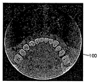
- region of interest corresponds to a portion of the object (in which the object refers to the entire head of the patient), as shown in FIG. It will be outside the region of interest.
- truncation artifact 100 This results in a phenomenon where the edges of the region of interest, in particular the region where the object is cut, are highlighted, which is called truncation artifact 100.
- the photographed image in which the truncation artifact is generated provides an image whose edge is emphasized, thereby providing an unclear photographed image.
- the present invention is to solve the above-mentioned disadvantages and problems of the prior art, a sharp image taken by correcting the truncation artifacts generated when the CT is photographed with a part of the object out of the region of interest by the LSF technique It is an object of the present invention to provide a method for correcting truncation artifacts that can be obtained.
- the object of the present invention comprises the steps of acquiring projection data by photographing an object; Setting a normal area and a truncation area in the projection data; Obtaining predictive projection data of the truncation region from the normal projection data of the normal region by using an LSF technique; Concatenating normal projection data and predictive projection data to obtain integrated projection data; And reconstructing the integrated projection data.
- a method of correcting a truncation artifact comprising: a.
- the object of the present invention is the first condition that the LSF technique must pass through the last point of the normal projection data, the second condition that the prediction projection data obtained by using the LSF technique must always be positive and the LSF technique
- the function derived is also achieved by a method of correcting the truncation artifact, characterized in that it satisfies all third conditions of convergence.
- the above object of the present invention is also achieved by a method for correcting truncation artifacts, characterized in that the function derived by the LSF technique is a quadratic equation.
- the method for correcting the truncation artifacts of the present invention has the effect of providing a clear image by correcting the truncation artifacts generated when photographing a portion of the object with the X-ray Citigraphy apparatus.
- 2 to 4 and 5 to 7 are diagrams for explaining the principle of the appearance of the truncation artifacts.
- FIG. 8 is a flowchart illustrating a method of correcting truncation artifacts according to an embodiment of the present invention.
- FIGS. 9, 10, and 11 are diagrams for describing a method of obtaining predictive projection data using the LSF technique from normal projection data.
- 16 to 18 illustrate diagrams of a case in which reconstruction without applying a method for correcting truncation artifacts and a case in which reconstruction is performed after application are performed according to an embodiment of the present invention.
- the object is placed between an X-ray source and a detector provided in the X-ray Citigraphic apparatus, and the X-ray generated by the X-ray source is irradiated to the object and received by the detector to receive data.
- These two-dimensional images obtain projection data.
- the X-ray source and the detector acquire a plurality of projection data while scanning by rotating the circular trajectory up to 360 degrees while moving by the same angle.
- the 3D image of the object is obtained by reconstructing the plurality of projection data into a 3D image.
- the 3D image reconstruction has various techniques, but in the present invention, the filter back-projection algorithm proposed by Feldkamp, Davis, and Kress (FDK) was used.
- the filter bag-projection algorithm is processed according to the following method.
- preprocessing and filtering are performed.
- the projection data acquired by the X-ray Citigraphy apparatus are loaded one by one.
- the Jacobian weighting process is a process for correcting a change in a value between polar coordinates and rectangular coordinates during a mathematical process.
- the projection data is filtered using a filter.
- the filtering becomes the core of the filter bag-projection algorithm technique.
- the shape of the object part derived as a result of the reconstruction appears blurred and unclear.
- each projection data is filtered so that the shape of the original object can be approximated.
- the filtering process is performed between the Jacobian weighting process and the back-projection process to be described later.
- interpolation is performed using the projection data to determine the value of each target point of the three-dimensional volume. And the value of the target point is stored.
- the reconstructed slice is then stored.
- Each of the projection data is sequentially processed through the preprocessing and filtering processing, the back-projection processing, and the reconstruction section storage, and then the reconstruction result is stored in the section.
- FIGS. 5 to 7 are diagrams for explaining the principle of the appearance of the truncation artifacts.
- 2 to 4 are diagrams illustrating a case in which truncation artifacts do not appear
- FIGS. 5 to 7 are diagrams illustrating a case in which truncation artifacts appear and compare the principle of generating truncation artifacts by comparing them. Able to know.
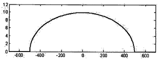
- the projection data When the projection data is displayed as data after performing the filtering process in the above-described three-dimensional reconstruction method, the projection data has a constant value as shown in FIG. 4.
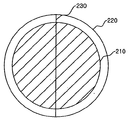
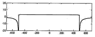
- FIG. 5 when only a part of the object 210, which is a cylindrical object, is included in the region of interest 220 and the rest is photographed while being outside the region of interest 220, the line 234 of FIG. Projection data whose value is suddenly changed at the edge 240 of the region of interest as shown in FIG. 6, which shows the projection data of the cut view according to FIG. 6), is filtered and processed as shown in FIG. 7. The filtering result is highlighted at the edge 240 of the region.
- the reconstruction section is obtained by reconstructing the projection data having the filtered graph as shown in FIG. 7, the image in which the edge 240 of the region of interest is highlighted, that is, the image in which the truncation artifact is generated, is shown in FIG. 1. You get it.
- FIG. 8 is a flowchart illustrating a method of correcting truncation artifacts according to an embodiment of the present invention.
- the X-ray imaging apparatus acquires a plurality of projection data while moving the X-ray source and the detector at a predetermined angle.
- the plurality of pieces of projection data may be preprocessed, filtered, back-projected, and reconstructed to store an image.
- a normal region and a truncation region are set from the projection data (S200).
- prediction projection data of the truncation region is obtained from the normal projection data of the normal region by using a Least Squares Fitting (LSF) technique (S300).
- LSF Least Squares Fitting
- the integrated projection data is obtained by connecting the normal projection data and the prediction projection data (S400).
- the prediction projection data of the truncation region may use an LSF technique from the normal projection data of the normal region.
- the LSF technique may predict the prediction projection data of the truncation region from the normal projection data of the normal region, and the prediction is predicted using the last point of the normal projection data of the normal region. That is, the prediction projection data of the truncation region may be obtained from the last point by the LSF technique.
- the LSF scheme will be described. As shown in FIG. 9, the difference between y i and f (x i ) in order to find the most conjoined function f (x) at a point (x i , y i ) is shown in FIG. 9. Determining f (x) so that the sum of squares of the portion corresponding to e) is the smallest is called the LSF technique can be represented by the following equation (1).
- ⁇ j is a parameter representing the characteristic of the function f (x).
- the prediction projection data of the truncation region must pass through the last point of the normal projection data of the normal region.
- the prediction projection data of the truncation region should always be positive.
- the prediction projection data of the truncation region should converge.
- the projection data generally has a convex shape, which is an even-order function such as quadratic and quadratic.
- Equation 2 the quadratic function can be expressed as Equation 2 below.
- Equation 5 The equations 3 and 4 can be summarized as shown in Equation 5 below.
- the quadratic and quadratic equations passing through the last point 300 of the normal region may be obtained from the projection data.
- the quadratic formula has a convex function but the quadratic formula diverges. Therefore, the quadratic formula does not satisfy the third of the three conditions. Since the even-numbered equation above the fourth-order is divergent as the fourth-order equation, it can be seen that in order to use the LSF technique of the present invention, the second-order equation should be used.
- FIG. 11 illustrates the result of changing the negative region to a positive number in order to satisfy the second condition among the above conditions in the second equation shown in FIG. 10.
- the projection data is actual projection data, that is, the LSF technique from the normal projection data 310 at the last point 300 of the normal projection data 310 of the normal region and the normal projection data 310.
- the prediction projection data 320 predicted by using the projection data when reconstructed using the projection data as shown in Figure 1 can be obtained without clearing the truncation artifacts.
- the sum of the normal projection data 310 and the prediction projection data 320 may be referred to as the integrated projection data described above.
- FIG. 12 is an interest in photographing a physical phantom 400 and a physical phantom 400 using an X-ray imaging apparatus to which a method for correcting truncation artifacts according to an embodiment of the present invention is applied. Shown is a schematic of the region 410.
- the radius of the physical phantom 400 is 1 and the radius of the ROI 410 is 0.9.
- the center of the region of interest 410 is 0.25 from the center of the physical phantom 400, a portion of the physical phantom 400 is out of the region of interest 410.
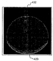
- the truncation artifact 420 is removed from the region where the physical pathum 400 deviates from the region of interest 410. Will occur.
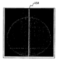
- the truncation artifact is located in an area in which the physical pattum 400 deviates from an area deviating from the region of interest 410. Will not occur.
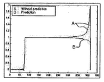
- FIG. 15 is a graph illustrating a result after filtering cut views of the lines 432 and 434 shown in FIGS. 13 and 14.
- the prediction projection data is subjected to prediction by applying the LSF method of the present invention. It shows the case of acquiring the integrated projection data by acquiring and the case where it is not predicted.
- the prediction projection data is predicted from the normal projection data using the LSF technique
- the longer the prediction length the length is equal to the number of pixels in the image
- the prediction projection data to be predicted by using the LSF method is larger to obtain a more accurate image.
- the prediction projection data is 100 points or more, there is no significant difference from the ideal case. Therefore, it is most preferable to predict the prediction projection data to about 150 points.
- 16 to 18 illustrate diagrams of a case in which a reconstruction without applying a method for correcting a truncation artifact and a case in which a reconstruction after applying is applied according to an embodiment of the present invention.
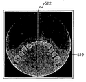
- FIG. 16 is a diagram illustrating a case of reconfiguring without applying a method for correcting truncation artifacts according to an embodiment of the present invention. While the truncation artifacts 510 are generated and highlighted at the edges of the ROI by deviating from FIG. In the drawings, even when the object, ie, the head of the patient, is out of the region of interest, no truncation artifacts are generated at the edge of the region of interest, so that the edge of the region of interest can also obtain a clear image.
- FIG. 18 illustrates data after filtering in cut views according to the lines 522 and 524 illustrated in FIGS. 16 and 17.
- Truncation artifacts are generated at the edges of the region of interest by the objects that are out of order. These truncation artifacts are corrected using the LSF technique before filtering and then reconstructed to obtain a clear image correcting the truncation artifacts.
Landscapes
- Health & Medical Sciences (AREA)
- Life Sciences & Earth Sciences (AREA)
- Engineering & Computer Science (AREA)
- Physics & Mathematics (AREA)
- Medical Informatics (AREA)
- Radiology & Medical Imaging (AREA)
- Heart & Thoracic Surgery (AREA)
- High Energy & Nuclear Physics (AREA)
- Theoretical Computer Science (AREA)
- Nuclear Medicine, Radiotherapy & Molecular Imaging (AREA)
- Optics & Photonics (AREA)
- Pathology (AREA)
- General Physics & Mathematics (AREA)
- Biomedical Technology (AREA)
- Biophysics (AREA)
- Molecular Biology (AREA)
- Surgery (AREA)
- Animal Behavior & Ethology (AREA)
- General Health & Medical Sciences (AREA)
- Public Health (AREA)
- Veterinary Medicine (AREA)
- Dentistry (AREA)
- Oral & Maxillofacial Surgery (AREA)
- Apparatus For Radiation Diagnosis (AREA)
Abstract
La présente invention concerne un procédé de correction d'artéfacts de troncature dans un appareil de tomographie dentaire aux rayons X pouvant asurer une telle correction d'artéfacts de troncature causés par la mise en image d'une déviation d'une partie de la tête d'un patient de la zone d'intérêt lors de la mise en image d'un objet (la tête d'un patient), au moyen d'une technique LSF qui rehausse les contours des images reconfigurées.
Applications Claiming Priority (2)
| Application Number | Priority Date | Filing Date | Title |
|---|---|---|---|
| KR10-2008-0004377 | 2008-01-15 | ||
| KR1020080004377A KR100923094B1 (ko) | 2008-01-15 | 2008-01-15 | 트렁케이션 아티팩트를 보정하는 방법 |
Publications (3)
| Publication Number | Publication Date |
|---|---|
| WO2009091202A2 true WO2009091202A2 (fr) | 2009-07-23 |
| WO2009091202A3 WO2009091202A3 (fr) | 2009-10-01 |
| WO2009091202A9 WO2009091202A9 (fr) | 2010-01-28 |
Family
ID=40885806
Family Applications (1)
| Application Number | Title | Priority Date | Filing Date |
|---|---|---|---|
| PCT/KR2009/000231 Ceased WO2009091202A2 (fr) | 2008-01-15 | 2009-01-15 | Procédé de correction d'artéfacts de troncature |
Country Status (2)
| Country | Link |
|---|---|
| KR (1) | KR100923094B1 (fr) |
| WO (1) | WO2009091202A2 (fr) |
Cited By (1)
| Publication number | Priority date | Publication date | Assignee | Title |
|---|---|---|---|---|
| CN111260771A (zh) * | 2020-01-13 | 2020-06-09 | 北京东软医疗设备有限公司 | 一种图像重建方法及装置 |
Families Citing this family (3)
| Publication number | Priority date | Publication date | Assignee | Title |
|---|---|---|---|---|
| KR20160057935A (ko) | 2014-11-14 | 2016-05-24 | 삼성전자주식회사 | 단층 영상 장치 및 그에 따른 단층 영상 복원 방법 |
| KR102379067B1 (ko) | 2014-12-01 | 2022-03-25 | 삼성전자주식회사 | 의료 영상 장치 및 의료 영상 처리 방법 |
| KR102387403B1 (ko) * | 2020-05-28 | 2022-04-14 | 건양대학교 산학협력단 | 잘림 아티팩트 저감 프로젝션 데이터 보정방법 |
Family Cites Families (4)
| Publication number | Priority date | Publication date | Assignee | Title |
|---|---|---|---|---|
| US4550371A (en) | 1982-09-27 | 1985-10-29 | General Electric Company | Method and apparatus for compensating CT images for truncated projections |
| JP3446327B2 (ja) * | 1994-08-31 | 2003-09-16 | 株式会社島津製作所 | 放射線撮像装置 |
| JP2003116824A (ja) | 2001-08-09 | 2003-04-22 | Shimadzu Corp | 放射線画像の補正方法及び放射線撮影装置 |
| JP4282302B2 (ja) | 2001-10-25 | 2009-06-17 | 株式会社東芝 | X線ct装置 |
-
2008
- 2008-01-15 KR KR1020080004377A patent/KR100923094B1/ko not_active Expired - Fee Related
-
2009
- 2009-01-15 WO PCT/KR2009/000231 patent/WO2009091202A2/fr not_active Ceased
Cited By (2)
| Publication number | Priority date | Publication date | Assignee | Title |
|---|---|---|---|---|
| CN111260771A (zh) * | 2020-01-13 | 2020-06-09 | 北京东软医疗设备有限公司 | 一种图像重建方法及装置 |
| CN111260771B (zh) * | 2020-01-13 | 2023-08-29 | 北京东软医疗设备有限公司 | 一种图像重建方法及装置 |
Also Published As
| Publication number | Publication date |
|---|---|
| WO2009091202A3 (fr) | 2009-10-01 |
| KR20090078513A (ko) | 2009-07-20 |
| KR100923094B1 (ko) | 2009-10-22 |
| WO2009091202A9 (fr) | 2010-01-28 |
Similar Documents
| Publication | Publication Date | Title |
|---|---|---|
| DE69635711T2 (de) | Nachweissystem und verfahren zur quantativen feststellung von zahnkaries | |
| Gröundahl et al. | Influence of variations in projection geometry on the detectability of periodontal bone lesions: a comparison between subtraction radiography and conventional radiographic technique | |
| Gröndahl et al. | Influence of variations in projection geometry on the detectability of periodontal bone lesions. | |
| WO2009091200A2 (fr) | Procédé d'élimination d'artéfacts métalliques dans des images tomographiques aux rayons x | |
| WO2005107597A1 (fr) | Dispositif d'imagerie par rayonnement permettant de corriger le mouvement d'un corps, procede de traitement d'image et programme informatique | |
| WO2013176310A1 (fr) | Procédé de réduction de bruit dans une image médicale | |
| WO2022039313A1 (fr) | Procédé et dispositif de correction d'artéfact métallique dans une image tomodensitométrique | |
| WO2013129811A1 (fr) | Procédé pour la réduction d'artefacts métalliques en tomodensitométrie (ct) | |
| WO2011087306A2 (fr) | Appareil d'imagerie par tomographie informatisée à rayons x et procédé s'y rapportant | |
| Sano et al. | Super-resolution method and its application to medical image processing | |
| WO2009091202A9 (fr) | Procédé de correction d'artéfacts de troncature | |
| CN118967584A (zh) | 一种基于图像分析的人体脊柱侧弯评估系统 | |
| JP4584550B2 (ja) | X線計測装置 | |
| WO2014193021A1 (fr) | Procédé et système de traitement d'images médicales | |
| JP2001095793A (ja) | X線ct装置 | |
| Van der Stelt et al. | Determination of projections for subtraction radiography based on image similarity measurements | |
| Loussot et al. | An oriented fractal analysis for the characterization of texture. application to bone radiographs | |
| JPS6152860A (ja) | X線ct装置 | |
| Mol et al. | Locating the periapical region in dental radiographs using digital image analysis | |
| KR101069026B1 (ko) | 치아우식증 분석을 위한 이미지 변환 시스템 및 그 방법 | |
| Hsieh et al. | Reconstruction technique for focal spot wobbling | |
| JP2004152043A (ja) | 差分画像の補正方法および画像処理装置 | |
| WO2018131733A1 (fr) | Procédé et appareil de réduction de bruit dans une image ct | |
| WO2017065591A1 (fr) | Système et procédé pour calculer automatiquement une dose efficace d'exposition à un rayonnement | |
| JP4387758B2 (ja) | Spect装置及びspect画像再構成方法 |
Legal Events
| Date | Code | Title | Description |
|---|---|---|---|
| 121 | Ep: the epo has been informed by wipo that ep was designated in this application |
Ref document number: 09702258 Country of ref document: EP Kind code of ref document: A2 |
|
| NENP | Non-entry into the national phase |
Ref country code: DE |
|
| 122 | Ep: pct application non-entry in european phase |
Ref document number: 09702258 Country of ref document: EP Kind code of ref document: A2 |