WO2009096008A1 - 操舵制御装置 - Google Patents
操舵制御装置 Download PDFInfo
- Publication number
- WO2009096008A1 WO2009096008A1 PCT/JP2008/051401 JP2008051401W WO2009096008A1 WO 2009096008 A1 WO2009096008 A1 WO 2009096008A1 JP 2008051401 W JP2008051401 W JP 2008051401W WO 2009096008 A1 WO2009096008 A1 WO 2009096008A1
- Authority
- WO
- WIPO (PCT)
- Prior art keywords
- torque
- motor
- steering
- time constant
- current
- Prior art date
- Legal status (The legal status is an assumption and is not a legal conclusion. Google has not performed a legal analysis and makes no representation as to the accuracy of the status listed.)
- Ceased
Links
Images




Classifications
-
- B—PERFORMING OPERATIONS; TRANSPORTING
- B62—LAND VEHICLES FOR TRAVELLING OTHERWISE THAN ON RAILS
- B62D—MOTOR VEHICLES; TRAILERS
- B62D5/00—Power-assisted or power-driven steering
- B62D5/04—Power-assisted or power-driven steering electrical, e.g. using an electric servo-motor connected to, or forming part of, the steering gear
- B62D5/0457—Power-assisted or power-driven steering electrical, e.g. using an electric servo-motor connected to, or forming part of, the steering gear characterised by control features of the drive means as such
- B62D5/046—Controlling the motor
-
- H—ELECTRICITY
- H02—GENERATION; CONVERSION OR DISTRIBUTION OF ELECTRIC POWER
- H02P—CONTROL OR REGULATION OF ELECTRIC MOTORS, ELECTRIC GENERATORS OR DYNAMO-ELECTRIC CONVERTERS; CONTROLLING TRANSFORMERS, REACTORS OR CHOKE COILS
- H02P6/00—Arrangements for controlling synchronous motors or other dynamo-electric motors using electronic commutation dependent on the rotor position; Electronic commutators therefor
- H02P6/10—Arrangements for controlling torque ripple, e.g. providing reduced torque ripple
Definitions
- the present invention relates to a steering control device, and more particularly to a steering control device for extracting and reducing pulsation components due to cogging torque and torque ripple of an electric motor.
- An electric power steering device is used as a steering control device for automobiles.
- the electric power steering device controls the current of the electric motor, transmits the electric motor torque generated according to the current to the steering shaft, and reduces the steering torque of the driver.
- the torque generated by the electric motor includes cogging torque and torque ripple.
- the cogging torque and torque ripple act as disturbance torque, and the steering torque pulsates, which may reduce the steering feeling.
- expensive motors have been used to reduce the cogging torque and torque ripple of the motor.
- a pulsation component due to cogging torque or torque ripple is extracted, and compensation control is performed by an electric motor so as to reduce the pulsation of the steering torque (see, for example, Patent Document 1).
- the driver freely steers the steering wheel, so the motor rotation angular velocity is an arbitrary speed. Since the cogging torque and torque ripple are torque pulsations generated depending on the motor rotation angle, the frequency of pulsations such as the steering torque generated by the cogging torque and torque ripple changes according to the motor rotation angular velocity. Therefore, when trying to extract cogging torque and torque ripple with a filter with a fixed time constant, it is necessary to set the passband frequency of the filter widely, components other than the pulsation component due to cogging torque and torque ripple, such as the steering component of the driver, Or, there has been a problem that noise components in a high frequency range cannot be sufficiently removed than pulsation components.
- the compensation control is set with the extracted pulsation component from which the driver's steering component, noise component, etc. are not sufficiently removed, the driver's steering feeling may change. Therefore, extracting a pulsation component due to cogging torque or torque ripple with high accuracy while the driver is steering the steering wheel is a big problem in performing compensation control for reducing the pulsation.
- the present invention has been made to solve such a problem, and accurately extracts pulsation components due to cogging torque and torque ripple from sensor information obtained by the driver while steering the steering wheel.
- Another object of the present invention is to obtain a steering control device capable of reducing pulsation such as steering torque caused by torque ripple.
- the present invention generates the assist torque based on the detected torque, a torque detector for detecting the steering torque by the driver, a motor for generating an assist torque for assisting the steering torque, and the detected steering torque.
- An electric power assist control unit that calculates an electric power assist target current of the motor necessary for the motor, an angle detection unit that detects a rotation angle of the motor, and the motor to match the electric power assist target current. The frequency of the cogging torque or torque ripple generated by the motor using the current control unit for controlling the current of the motor, the time constant variable filter having a variable time constant, and the rotation angle of the motor detected by the angle detection unit.
- a time constant calculating unit that calculates a corresponding time constant and sets the time constant in the time constant variable filter; and the steering torque
- a steering control system that includes a filter processing computing section for filtering by and the time constant variable filter state quantity of the rotation angle and the like of the motor.
- the present invention generates the assist torque based on the detected torque, a torque detector for detecting the steering torque by the driver, a motor for generating an assist torque for assisting the steering torque, and the detected steering torque.
- An electric power assist control unit that calculates an electric power assist target current of the motor necessary for the motor, an angle detection unit that detects a rotation angle of the motor, and the motor to match the electric power assist target current. The frequency of the cogging torque or torque ripple generated by the motor using the current control unit for controlling the current of the motor, the time constant variable filter having a variable time constant, and the rotation angle of the motor detected by the angle detection unit.
- a time constant calculating unit that calculates a corresponding time constant and sets the time constant in the time constant variable filter; and the steering torque And a filter processing calculation unit that filters a state quantity such as the rotation angle of the motor and the motor with the time constant variable filter, so that the sensor information obtained while the driver is steering the steering wheel It is possible to accurately extract pulsation components due to cogging torque and torque ripple, and to reduce pulsations such as steering torque due to cogging torque and torque ripple.
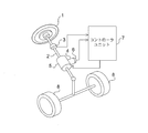
- FIG. 1 is a perspective view showing a steering control device including a time constant variable filter according to Embodiment 1 of the present invention.
- a steering shaft 2 is connected to a steering wheel 1 operated by a driver.
- the left and right steered wheels 8 are steered according to the rotation of the steering shaft 2.
- a torque sensor 3 is disposed on the steering shaft 2 and detects a steering torque generated by a driver's operation acting on the steering shaft 2.
- the motor 4 is composed of a three-phase motor.
- the motor 4 is connected to the steering shaft 2 via the speed reduction mechanism 5, and the assist torque generated by the motor 4 is applied to the steering shaft 2 to assist the steering torque.
- the motor 4 is provided with an angle sensor 6 that detects a motor rotation angle.
- the vehicle speed of the vehicle is detected by a vehicle speed sensor 11 (described in FIG. 2). Further, the current flowing through the motor 4 is detected by a current sensor 19 (described in FIG. 2).
- the controller unit 7 includes an electric power assist control unit 71 and a current control unit 72.
- the electric power assist control unit 71 performs the electric power assist control for assisting the driver's steering steering from the steering torque detected by the torque sensor 3 and the vehicle speed detected by the vehicle speed sensor 11.
- a target current for electric power assist which is a target current, is calculated.
- the electric power assist target current corresponds to the assist torque target value.
- the current control unit 72 controls the current of the motor 4 so that the current detected by the current sensor 19 matches the target current for electric power assist.
- FIG. 2 is a block diagram showing the main part of the controller unit 7.
- the controller unit 7 includes a switching element drive circuit 21 and an inverter 22 as shown in FIG. 2 in addition to the electric power assist control unit 71 and the current control unit 72 described above.
- the inverter 22 has six switching elements 61A to 63A and 61B to 63B. Switching elements 61 ⁇ / b> A and 61 ⁇ / b> B form a pair, and they are connected to one of the three phases of motor 4.
- switching elements 62 ⁇ / b> A and 62 ⁇ / b> B constitute a pair
- switching elements 63 ⁇ / b> A and 63 ⁇ / b> B constitute a pair, which are connected to another of the three phases of motor 4.
- each of the switching elements 61B to 63B is provided with a current sensor 19, and these current sensors 19 detect a current flowing through each phase of the motor.
- the electric power assist controller 71 receives the vehicle speed signal detected by the vehicle speed sensor 11 via the interface 31 and the steering torque signal detected by the torque sensor 3 via the interface 32.
- the electric power assist controller 71 determines the direction and magnitude of the motor torque according to the vehicle speed signal and the steering torque signal, thereby calculating the electric power assist target current and inputting it to the current controller 72.
- the interface 33 receives a motor rotation angle signal from the angle sensor 6 and inputs the motor rotation angle to the electric power assist control unit 71 and the current control unit 72.
- the interface 34 receives the detected current signals of the respective phases of the motor from the three current sensors 19 and inputs the detected current of the motor to the current control unit 72.
- the current control unit 72 calculates a voltage command according to the electric power assist target current, the detected current of the motor, and the rotation angle of the motor.
- the switching element drive circuit 21 performs PWM modulation on the voltage command and instructs the inverter 22 to perform a switching operation.
- the inverter 22 receives the switching operation signal, realizes chopper control of the switching elements 61A to 63A and 61B to 63B, and causes a current to flow to the motor 4 by the electric power supplied from the battery 23. This current generates motor torque, that is, assist torque.
- the configuration of the inverter 22 described above corresponds to a three-phase motor. However, when the motor 4 is a brushed DC motor, an H bridge circuit may be used.
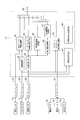
- FIG. 3 is a block diagram showing the configuration of the electric power assist controller 71.
- the electric power assist controller 71 is composed of a microcomputer.
- the outputs of the vehicle speed sensor 11, the torque sensor 3, the angle sensor 6, and the current sensor 19 are read into the microcomputer as digital values for each predetermined sampling time via the interfaces 31 to 34.
- the electric power assist controller 71 includes a phase compensator 35, a basic assist current calculator 36, an angular velocity calculator 37, a damping compensation current calculator 38, a friction compensation current calculator 39, and an angular acceleration calculator 40.
- An inertia compensation current calculator 41, an observer damping compensation current calculator 42, a pulsation component extractor 44, and a pulsation compensation current calculator 45 are provided.
- reference numeral 43 denotes an electric power assist target current output by the electric power assist control unit 71.
- the phase compensator 35 receives the steering torque detected by the torque sensor 3 and performs phase compensation on the steering torque to improve the frequency characteristics.
- the basic assist current compensator 36 stores in advance the value of the basic assist current according to the steering torque and the vehicle speed after phase compensation as a map value.
- the basic assist current compensator 36 uses the stored map value to perform phase compensation.
- a basic assist current is calculated according to the subsequent steering torque and vehicle speed. When the vehicle speed is low, by increasing the value of the basic assist current with respect to the steering torque after phase compensation, the steering torque of the driver during low speed traveling such as parking is reduced, and steering is facilitated.
- the basic assist current compensator 36 has been described with respect to the method for obtaining the basic assist current by map computation, it may be obtained by computation by multiplying the gain.
- the angular velocity calculator 37 differentiates the motor rotation angle detected by the angle sensor 6 and calculates the motor rotation angular velocity.
- the damping compensation current calculator 38 calculates the damping compensation current by multiplying the motor rotation angular velocity by the control gain.
- the damping compensation current has the effect of improving the convergence of the steering wheel.
- constants such as a map and a proportional coefficient necessary for calculation such as control gain are set in the ROM in advance.
- the friction compensation current calculator 39 calculates a friction compensation current based on the sign of the motor rotational angular velocity. The friction compensation current changes according to the sign of the motor rotational angular velocity.
- the friction compensation current is a current for causing the motor 4 to generate a torque for canceling the friction existing in the steering mechanism, and has an effect of improving the steering feeling.
- the angular acceleration calculator 40 differentiates the motor rotation angular velocity calculated by the angular velocity calculator 37 to calculate the motor rotation angular acceleration.
- the inertia compensation current calculator 41 calculates an inertia compensation current from the motor rotation angular acceleration. Since the inertia compensation current cancels the inertia force of the motor, the steering feeling is improved.
- the observer damping compensation current calculator 42 estimates the vibration speed of the motor 4 using the observer from the steering torque detected by the torque sensor 3 and the current of the motor 4 detected by the current sensor 19, and applies the damping torque. The observer damping compensation current is calculated.
- the steering mechanism is represented by a balance of steering torque input by the driver moving the steering wheel, assist torque generated by the motor, and reaction torque centered on reaction force from the tire.
- steering vibration generally occurs at a fast frequency of 30 Hz or higher. At this fast frequency, fluctuations in steering wheel angle and road surface reaction force fluctuations are negligibly small, so that the motor 4 can be regarded as a vibration system supported by a torque sensor having spring characteristics.
- the rotational speed observer is configured based on a corresponding equation of motion, for example, a vibration equation in which the moment of inertia of the motor is the inertia term and the rigidity of the torque sensor is the spring term, the voltage drop in the coil from the coil current
- the rotational speed of the motor in the frequency band exceeding the steering frequency can be estimated without using a differentiator necessary for obtaining.
- the calculation in the observer damping compensation current calculator 42 can also be performed using the current of the motor 4 detected by the current sensor 19 and the motor rotation angle detected by the angle sensor 6, but in this embodiment, torque Calculation is performed using the steering torque detected by the sensor 3 and the current of the motor 4 detected by the current sensor 19.
- torque Calculation is performed using the steering torque detected by the sensor 3 and the current of the motor 4 detected by the current sensor 19.
- the torsion angle of the torque sensor having spring characteristics can be regarded as the motor rotation angle
- the torque sensor output is divided by the spring constant of the torque sensor
- the steering frequency component is removed
- the sign is inverted, whereby the motor A signal equivalent to a rotation angle of 4 can be obtained.
- the observer damping compensation current calculator 42 uses a vibration equation in which the moment of inertia of the motor is the inertia term and the rigidity of the torque sensor is the spring term, and the motor detected by the current sensor 19 and the signal equivalent to the rotation angle of the motor 4. 4 to estimate the rotational speed.
- the observer damping compensation current calculator 42, the basic assist current calculator 36, the damping compensation current calculator 38, the friction compensation current calculator 39, and the inertia compensation current calculator 41 are known techniques described in Japanese Patent No. 3712876 and the like. It is.
- the basic assist current, damping compensation current, friction compensation current, inertia compensation current, and observer damping compensation current obtained as described above are added by an adding means such as an adder for electric power assist.
- a target current 43 is obtained.
- the pulsation component extractor 44 removes a steering component detected by the torque sensor 3 from the steering component of the driver and a noise component in a higher frequency range than the pulsation component, and extracts a pulsation component of the steering torque by cogging torque or torque ripple.
- FIG. 4 is a block diagram illustrating a configuration example of the pulsation component extractor 44. As shown in FIG. 4, the pulsation component extractor 44 includes a time constant calculator 51 and a band pass filter 52.
- the value obtained by dividing the number of torque pulsations generated per rotation of the motor by the number of pole pairs Pn is the torque ripple generation harmonic order n.
- the frequency fn [Hz] of the torque ripple changes according to the motor rotational angular velocity d ⁇ m / dt.
- the center frequency fc of the bandpass filter is set to be equal to fn as shown in equation (2-2).
- time constant Tc of the bandpass filter is set by the equation (2-3).
- the time constant variable filter that sets the time constant of the bandpass filter is applied to the steering torque detected by the torque sensor 3, if the time constant variable filter is applied to the steering torque detected by the torque sensor 3, the driver's steering component and pulsation component It is possible to remove a noise component or the like in a high frequency region and extract a pulsation component of a steering torque due to cogging torque or torque ripple.
- the bandpass filter 52 for example, a fourth-order bandpass filter shown in Expression (3) is used.
- Gbpf is a transfer function of the filter
- s is a Laplace operator.
- K1 is a correction gain for the gain of ⁇ 12 dB at the center frequency fc [Hz]
- K1 is set so that the gain is 0 dB at the center frequency fc [Hz].
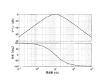
- FIG. 7 shows the frequency response characteristics of the bandpass filter when the center frequency fc is 10 Hz. From the characteristics of FIG. 7, at the center frequency fc (10 Hz), a pulsation component can be extracted with a gain of 0 dB and a phase delay of 0, and other components can be removed with a slope of ⁇ 40 dB / decade in both low and high frequencies. The pulsation component can be extracted from the filter input signal 53 with high accuracy.
- the pulsation component is also included in the rotational angular velocity d ⁇ m / dt of the motor obtained by differentiating the motor rotation angle. That is, as shown in equation (2-1), when the torque ripple frequency fn is calculated using the motor rotation angular velocity d ⁇ m / dt obtained by differentiating the motor rotation angle and the time constant of the bandpass filter is changed, The constant varies with the torque ripple frequency.
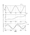
- FIG. 5 is a diagram showing the results of bandpass filter processing using a pulsating time constant.
- L1 represents the center frequency set by the rotational angular velocity d ⁇ m / dt including the pulsation component.
- L2 is a steering torque input to the bandpass filter, and includes a steering component and a pulsation component.
- L3 is a pulsation component added to the steering torque component.
- L4 is an output value of the band pass filter.
- the pulsation component extractor 44 is further added with a measure for suppressing the pulsation of the time constant. This eliminates distortion due to time constant pulsation, removes the driver's steering components from the steering torque detected by the torque sensor 3, noise components in a higher frequency range than the pulsation components, etc., and steer torque by cogging torque or torque ripple.
- the pulsation component is extracted with high accuracy.
- FIG. 6 is a flowchart showing a series of operations of the pulsation component extractor 44.
- a time constant calculator 51 is used to calculate the time constant of the bandpass filter from the motor rotation angle.
- As the input signal 53 to the band-pass filter 52 for example, a signal for extracting a pulsation component such as a steering torque and a motor rotation angle is input.
- the bandpass filter 52 is, for example, the above equation (3).
- a series of operations of the pulsation component extractor 44 will be described with reference to the flowchart of FIG.
- the initial value of the center frequency fc is an upper limit value of the center frequency fc described later.
- step S1 the steering torque Ts subjected to A / D conversion (analog / digital conversion) and the motor rotation angle ⁇ m [k] are stored in the memory via the interfaces 32 and 33.
- step S2 the deviation between the previous value ⁇ m [k ⁇ 1] of the motor rotation angle and the motor rotation angle ⁇ m [k] is calculated as shown in Expression (4), and the integrated value ⁇ m [ k].
- ⁇ m ⁇ m + ⁇ m [k] - ⁇ m [k-1] (4)
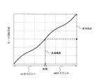
- step S3 the number of samplings cnt required until the integrated value ⁇ m [k] of the change amount of the motor rotation angle becomes equal to or larger than the reference angle ⁇ mr is counted. That is, cnt ⁇ Tsmp is a time required for the integrated value ⁇ m [k] of the change amount of the motor rotation angle to be equal to or larger than the reference angle ⁇ mr.
- step S4 the absolute value of the integrated value ⁇ m [k] of the change amount of the motor rotation angle is compared with the preset reference angle ⁇ mr.
- the process proceeds to step S5, and the absolute value of the integrated value ⁇ m [k] of the change amount of the motor rotation angle is equal to or greater than the reference angle ⁇ mr. In this case, the process proceeds to step S6.
- the reference angle ⁇ mr is set by equation (5) according to the harmonic order n of the torque ripple to be extracted.
- K2 is an integer gain.
- 360 / n is a reference angle corresponding to one cycle of cogging torque or torque ripple to be extracted.
- the reference angle ⁇ mre is an integral multiple of 60 deg.
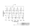
- FIG. 8 shows the effect obtained by setting the reference angle as shown in the present embodiment.
- step S6 the center frequency is set from equation (7) using the number of times of sampling cnt required to reach the reference angle ⁇ mr or more.
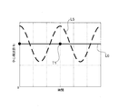
- FIG. 10 shows the effect of the method for setting the center frequency of the present invention.
- T1 indicates the timing at which the time constant is calculated in step S6.
- L5 is the result of calculating the rotational angular velocity d ⁇ m / dt of the motor at each sampling and setting the center frequency fc from equations (2-1) and (2-2).
- L6 is the result of setting the center frequency fc from equation (7) of the present embodiment.
- Ts 1 / (2 ⁇ fc) is calculated from the center frequency fc.
- the time constant is a constant value until the time constant is updated.
- the filter becomes a time constant time-invariant filter and is resistant to noise and the like. Even if the steering speed changes and the torque ripple frequency fn changes by the method of setting the time constant of the present embodiment, the influence of the rotational angle pulsation component is removed, and the time constant corresponding to the torque ripple frequency fn is set. can do.
- a lower limit value and an upper limit value are set for the center frequency fc.
- the lower limit value is 5 Hz or more. This is because if the center frequency fc is less than or equal to the lower limit value, the frequency of the driver's steering component and the pulsation component due to torque ripple will be close, and the driver's steering component may not be sufficiently removed from the bandpass filter output value.
- the upper limit value may be set as the upper limit value of the frequency region to be extracted. In the digital filter, an upper limit value may be set from the Nyquist frequency.
- step S7 the sampling count cnt and the integrated value ⁇ m [k] of the change amount of the motor rotation angle are reset to zero.
- step S5 the motor rotation angle ⁇ m [k] is stored in ⁇ m [k ⁇ 1].
- step S8 the filtering process shown in Expression (3) using the set time constant is performed, and the output signal 54 is output.
- the steering torque Ts is used as the filter input signal 53.
- FIG. 11 L7 indicates the center frequency set by equation (7) of the present embodiment.
- L8 is the output value of the bandpass filter.
- L2 and L3 are the same as those in FIG. Comparing L1 in FIG. 5 with L7 in FIG. 11, L7 can remove the pulsation component of the center frequency fc of the bandpass filter according to the present embodiment, and compared with L4 in FIG. 11 indicates that the pulsation component of the steering torque can be accurately extracted.
- the respective reference angles and the respective sampling times cnt may be calculated according to the respective torque ripple generation harmonic orders.
- the pulsating component having the smaller torque ripple generation harmonic order may affect the sampling number cnt having the larger order.
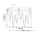
- FIG. 12 is a diagram showing the setting of the reference angle when there are a plurality of extracted pulsation components.
- a pulsation compensation current for reducing the pulsation component is calculated according to the pulsation component extracted by the pulsation component extractor 44.
- the pulsation compensation current is obtained by multiplying the pulsation component extracted by the pulsation component extractor 44 by a proportional gain.
- the electric power assist target current is corrected by adding the pulsation compensation current to the electric power assist target current.
- the current control unit 72 shown in FIG. 2 can reduce pulsation such as cogging torque and steering torque caused by torque ripple by controlling the current of the motor 4 so as to match the corrected target current for electric power assist. .
- the present embodiment can set the time constant from which the pulsation component is removed, and the time constant is changed according to the torque ripple frequency. Therefore, even when the driver is steering, the state used in the steering control device Steering components and noise are removed from the amount, for example, steering torque and motor rotation angle, components other than pulsation components due to cogging torque and torque ripple whose frequency changes are removed, and pulsation components due to cogging torque and torque ripple are accurately extracted There is an effect that can be. Further, since the pulsation component due to the cogging torque and torque ripple included in the time constant can be reduced, distortion of the output value of the bandpass filter can be suppressed, and the pulsation component due to the cogging torque and torque ripple can be accurately extracted. Furthermore, since the pulsation compensation current is calculated using the extracted pulsation component, the pulsation generated in the steering torque or the like can be appropriately reduced while preventing interference with the steering feeling.
- the time constant calculator 51 calculates the time constant based on the time required for the rotation angle of the motor 4 to rotate at the preset reference angle, the steering component is calculated from the state quantity such as the steering torque. And noise can be removed, pulsation components for cogging torque and torque ripple with changing frequency can be extracted with high accuracy, and pulsation of time constant can be suppressed, so that distortion of filter output value can be reduced and cogging with changing frequency The pulsation component for torque and torque ripple can be extracted with higher accuracy.
- the reference angle preset for the rotation angle of the motor 4 is an integral multiple of the rotation angle corresponding to one cycle of cogging torque or torque ripple, the steering component and noise are removed from the state quantity such as the steering torque. Therefore, it is possible to accurately extract pulsation components for cogging torque and torque ripple whose frequency changes, and to suppress the pulsation of the time constant, so that distortion of the filter output value can be reduced, and the cogging torque and torque ripple whose frequency changes can be reduced.
- the pulsation component can be extracted with higher accuracy.
- the target current for electric power assist is corrected according to the output signal of the time constant variable filter, the pulsation of the steering torque due to the cogging torque or the torque ripple can be suppressed.
- the bandpass filter is represented by Expression (3), but the present invention is not limited to this.
- the lower cutoff frequency fc1 and the upper cutoff frequency fc2 may be set to different values.
- a Butterworth filter or an elliptic filter may be used. Thereby, it is possible to obtain a steeper cutoff characteristic as compared with the expression (3).
- the order of the filter is set to the fourth order in Expression (3), the order is not limited to this.
- a secondary filter may be used. In that case, the calculation load is reduced.
- a fourth or higher order filter is preferably used.
- the filter is a band pass filter, but the time constant setting method of the first embodiment can be applied to the setting of the time constant of the low pass filter or the high pass filter.
- the time constant of the high-pass filter is set by the method of the present invention, and the time constant of the low-pass filter is set to a constant value, so that the calculation load can be reduced.
- the calculation of the time constant is calculated using the motor rotation angle.
- the calculation is not limited to the motor rotation angle, but is related to the motor rotation angle such as the rotation angle of the staying wheel.
- the estimated motor rotation angle may be used.
- the signal input to the filter is not limited to the steering torque, and may be a state quantity used in the steering control device, for example, a motor rotation angle, a motor rotation speed, or the like.
Landscapes
- Engineering & Computer Science (AREA)
- Power Engineering (AREA)
- Chemical & Material Sciences (AREA)
- Combustion & Propulsion (AREA)
- Transportation (AREA)
- Mechanical Engineering (AREA)
- Steering Control In Accordance With Driving Conditions (AREA)
- Power Steering Mechanism (AREA)
- Control Of Motors That Do Not Use Commutators (AREA)
- Control Of Electric Motors In General (AREA)
Abstract
Description
図1は、この発明の実施の形態1による時定数可変フィルタを備えた操舵制御装置を示す斜視図である。運転者が操作するステアリングホイール1にステアリング軸2が連結されている。ステアリング軸2の回転に応じて左右の転舵輪8が転舵される。ステアリング軸2には、トルクセンサ3が配置され、ステアリング軸2に作用する運転者の操作により発生する操舵トルクを検出する。モータ4は三相モータから構成されている。モータ4は、減速機構5を介してステアリング軸2に連結されており、モータ4が発生するアシストトルクは、ステアリング軸2に付与され、操舵トルクを補助する。モータ4には、モータ回転角度を検出する角度センサ6が配置されている。車両の車速は車速センサ11(図2に記載)で検出する。また、モータ4に流れる電流は電流センサ19(図2に記載)で検出する。コントローラユニット7は、電動パワーアシスト制御部71と電流制御部72とを備えている。電動パワーアシスト制御部71は、トルクセンサ3で検出した操舵トルクと車速センサ11で検出した車速とから、運転者のステアリング操舵をアシストする電動パワーアシスト制御を実施するために必要な、モータ4の目標電流である電動パワーアシスト用目標電流を演算する。電動パワーアシスト用目標電流は、アシストトルクの目標値に相当する。電流制御部72は、電流センサ19で検出した電流が、電動パワーアシスト用目標電流に一致するように、モータ4の電流を制御する。

Claims (4)
- 運転者による操舵トルクを検出するトルク検出部と、
前記操舵トルクを補助するためのアシストトルクを発生するモータと、
前記検出された操舵トルクに基づいて、前記アシストトルクを発生するのに必要な前記モータの電動パワーアシスト用目標電流を演算する電動パワーアシスト制御部と、
前記モータの回転角度を検出する角度検出部と、
前記電動パワーアシスト用目標電流に一致するように、前記モータの電流を制御する電流制御部と、
可変の時定数を有する時定数可変フィルタと、
前記角度検出部で検出する前記モータの回転角度を用いて、前記モータが発生するコギングトルクまたはトルクリプルの周波数に対応する時定数を演算し、当該時定数を前記時定数可変フィルタに設定する時定数演算部と、
前記操舵トルクや前記モータの回転角度等の状態量を前記時定数可変フィルタによりフィルタ処理するフィルタ処理演算部と
を備えたことを特徴とする操舵制御装置。 - 前記時定数演算部は、前記モータの回転角度に対する基準角度を予め設定しておき、前記モータの回転角度が前記基準角度を回転するのに要する時間に基づいて前記時定数を演算することを特徴とする請求項1に記載の操舵制御装置。
- 前記基準角度は、前記コギングトルクまたは前記トルクリプルの1周期分に相当する回転角度の整数倍とすることを特徴とする請求項2に記載の操舵制御装置。
- 前記時定数可変フィルタの出力信号に応じて、前記電動パワーアシスト用目標電流を補正するための補償電流を演算する補償電流演算部をさらに備え、
前記補償電流を前記電動パワーアシスト用目標電流に加算することで、前記電動パワーアシスト用目標電流を補正することを特徴とする請求項1ないし3のいずれか1項に記載の操舵制御装置。
Priority Applications (6)
| Application Number | Priority Date | Filing Date | Title |
|---|---|---|---|
| CN2008801259374A CN101932489B (zh) | 2008-01-30 | 2008-01-30 | 操纵控制装置 |
| EP08704164.6A EP2246238B1 (en) | 2008-01-30 | 2008-01-30 | Steering controller |
| PCT/JP2008/051401 WO2009096008A1 (ja) | 2008-01-30 | 2008-01-30 | 操舵制御装置 |
| KR1020107016329A KR101282510B1 (ko) | 2008-01-30 | 2008-01-30 | 조타 제어 장치 |
| US12/811,281 US8437915B2 (en) | 2008-01-30 | 2008-01-30 | Steering controller |
| JP2009551359A JP5235906B2 (ja) | 2008-01-30 | 2008-01-30 | 操舵制御装置 |
Applications Claiming Priority (1)
| Application Number | Priority Date | Filing Date | Title |
|---|---|---|---|
| PCT/JP2008/051401 WO2009096008A1 (ja) | 2008-01-30 | 2008-01-30 | 操舵制御装置 |
Publications (1)
| Publication Number | Publication Date |
|---|---|
| WO2009096008A1 true WO2009096008A1 (ja) | 2009-08-06 |
Family
ID=40912377
Family Applications (1)
| Application Number | Title | Priority Date | Filing Date |
|---|---|---|---|
| PCT/JP2008/051401 Ceased WO2009096008A1 (ja) | 2008-01-30 | 2008-01-30 | 操舵制御装置 |
Country Status (6)
| Country | Link |
|---|---|
| US (1) | US8437915B2 (ja) |
| EP (1) | EP2246238B1 (ja) |
| JP (1) | JP5235906B2 (ja) |
| KR (1) | KR101282510B1 (ja) |
| CN (1) | CN101932489B (ja) |
| WO (1) | WO2009096008A1 (ja) |
Cited By (5)
| Publication number | Priority date | Publication date | Assignee | Title |
|---|---|---|---|---|
| JP2011121383A (ja) * | 2009-12-08 | 2011-06-23 | Mitsubishi Electric Corp | 電動パワーステアリング制御装置 |
| JP2012110111A (ja) * | 2010-11-17 | 2012-06-07 | Toyo Electric Mfg Co Ltd | 電動機の制御装置 |
| CN102548830A (zh) * | 2009-10-02 | 2012-07-04 | 蒂森克鲁伯普雷斯塔股份公司 | 用于电动伺服转向器的控制方法 |
| WO2014061083A1 (ja) * | 2012-10-15 | 2014-04-24 | 三菱電機株式会社 | 電動車両のモータ制御装置 |
| JP2021079869A (ja) * | 2019-11-21 | 2021-05-27 | 株式会社デンソー | 電駆動システムの制御装置および電動航空機 |
Families Citing this family (20)
| Publication number | Priority date | Publication date | Assignee | Title |
|---|---|---|---|---|
| WO2008108292A1 (ja) * | 2007-03-07 | 2008-09-12 | Kabushiki Kaisha Yaskawa Denki | モータ制御装置とモータおよびトルクリプル補正方法 |
| GB201003456D0 (en) * | 2010-03-02 | 2010-04-14 | Trw Ltd | Current sensor error compensation |
| WO2011158876A1 (ja) * | 2010-06-18 | 2011-12-22 | 日立オートモティブシステムズ株式会社 | 電子制御装置 |
| US8996250B2 (en) * | 2011-09-09 | 2015-03-31 | Steering Solutions Ip Holding Corporation | Inertia compensation with frequency dependent damping |
| US8606476B2 (en) * | 2012-01-18 | 2013-12-10 | GM Global Technology Operations LLC | Closed-loop clutch control using a filtered piston position signal |
| CN102991662B (zh) * | 2012-12-24 | 2015-04-15 | 上海海事大学 | 一种艉轴双螺旋桨电力推进船舶的舵效补偿装置及方法 |
| CN105209320B (zh) * | 2013-05-10 | 2017-03-08 | 三菱电机株式会社 | 电动助力转向控制装置及转向控制方法 |
| JP6314552B2 (ja) * | 2014-03-07 | 2018-04-25 | 株式会社ジェイテクト | 電動パワーステアリング装置 |
| JP5935960B2 (ja) * | 2014-03-25 | 2016-06-15 | 日本精工株式会社 | 電動パワーステアリング装置 |
| JP6467209B2 (ja) * | 2014-12-09 | 2019-02-06 | オークマ株式会社 | 電動機のコギングトルク測定方法 |
| EP3239020B1 (en) * | 2014-12-26 | 2019-11-20 | NSK Ltd. | Electric power steering device |
| CN104590370B (zh) * | 2014-12-30 | 2017-04-19 | 安徽铜冠机械股份有限公司 | 铰接式车辆的辅助转向系统 |
| JP6491497B2 (ja) * | 2015-02-26 | 2019-03-27 | 山洋電気株式会社 | モータ制御装置 |
| KR101684513B1 (ko) * | 2015-04-28 | 2016-12-08 | 현대자동차 주식회사 | Mdps 시스템의 복원 제어장치 |
| US12017707B2 (en) * | 2018-02-20 | 2024-06-25 | Nidec Corporation | Motor control system and power steering system |
| US11498611B2 (en) * | 2018-05-11 | 2022-11-15 | Nidec Corporation | Motor control device, driving device, and power steering device |
| JP7075318B2 (ja) * | 2018-09-14 | 2022-05-25 | 日立Astemo株式会社 | ステアリング装置 |
| JP7247508B2 (ja) * | 2018-09-28 | 2023-03-29 | 日本電産株式会社 | ステアリング制御装置およびパワーステアリング装置 |
| KR102156259B1 (ko) * | 2020-01-08 | 2020-09-15 | 이래에이엠에스 주식회사 | 전동 파워 스티어링 시스템 |
| JP7572002B2 (ja) * | 2021-04-16 | 2024-10-23 | アルプスアルパイン株式会社 | 回転角度検出方法、回転角度検出プログラム、及び、回転角度検出装置 |
Citations (13)
| Publication number | Priority date | Publication date | Assignee | Title |
|---|---|---|---|---|
| JPS6124319A (ja) * | 1984-07-12 | 1986-02-03 | Toshiba Corp | 制御系入力用検出装置 |
| JPH02193768A (ja) * | 1989-01-23 | 1990-07-31 | Hitachi Ltd | 電動パワーステアリング装置 |
| JPH0635506A (ja) * | 1992-07-16 | 1994-02-10 | Toyo Electric Mfg Co Ltd | 可変構造制御方法 |
| JPH10310072A (ja) * | 1997-05-09 | 1998-11-24 | Kayaba Ind Co Ltd | 電動式パワーステアリングシステム |
| JPH10324262A (ja) * | 1997-05-22 | 1998-12-08 | Kayaba Ind Co Ltd | 電動式パワーステアリングシステム |
| JP2000312499A (ja) * | 1999-04-27 | 2000-11-07 | Meidensha Corp | 誘導電動機のベクトル制御装置 |
| JP2001258282A (ja) * | 2000-03-10 | 2001-09-21 | Toyoda Mach Works Ltd | 電動モータの制御装置およびそれを用いた電気式動力舵取装置 |
| JP2003137110A (ja) * | 2001-11-05 | 2003-05-14 | Koyo Seiko Co Ltd | 電動パワーステアリング装置 |
| JP2005067359A (ja) | 2003-08-22 | 2005-03-17 | Koyo Seiko Co Ltd | 電動パワーステアリング装置 |
| JP3712876B2 (ja) | 1998-12-01 | 2005-11-02 | 三菱電機株式会社 | 電動式パワーステアリング制御装置 |
| JP2006036078A (ja) * | 2004-07-28 | 2006-02-09 | Nsk Ltd | 電動パワーステアリング装置 |
| JP2006149176A (ja) * | 2004-11-25 | 2006-06-08 | Japan Servo Co Ltd | モータ制御装置 |
| JP3884236B2 (ja) | 2001-02-06 | 2007-02-21 | 株式会社ジェイテクト | 電動パワーステアリング装置 |
Family Cites Families (12)
| Publication number | Priority date | Publication date | Assignee | Title |
|---|---|---|---|---|
| JPS63204159A (ja) | 1987-02-20 | 1988-08-23 | Canon Inc | 周波数/電圧変換装置 |
| JP2551132B2 (ja) | 1989-01-26 | 1996-11-06 | ダイキン工業株式会社 | 電動機の駆動制御装置 |
| JP2001251880A (ja) | 2000-03-03 | 2001-09-14 | Yaskawa Electric Corp | サーボ制御装置 |
| JP4623824B2 (ja) | 2000-12-28 | 2011-02-02 | カヤバ工業株式会社 | 電動パワーステアリング制御装置 |
| JP4009589B2 (ja) * | 2001-06-08 | 2007-11-14 | デルファイ・テクノロジーズ・インコーポレーテッド | 電気パワーステアリングシステムのための速度補償制御 |
| JP3895635B2 (ja) | 2002-04-25 | 2007-03-22 | 三菱電機株式会社 | 電動式パワーステアリング制御装置 |
| US6789641B2 (en) * | 2002-08-14 | 2004-09-14 | Trw Inc. | Method and apparatus for controlling an electric assist motor using a modified blending filter |
| JP2005082034A (ja) * | 2003-09-09 | 2005-03-31 | Koyo Seiko Co Ltd | 電動パワーステアリングシステム |
| JP4223916B2 (ja) | 2003-10-07 | 2009-02-12 | 三菱電機株式会社 | 電動式パワーステアリング制御装置 |
| EP1616774A3 (en) * | 2004-07-15 | 2007-08-08 | NSK Ltd., | Electric power steering apparatus |
| US7068001B2 (en) | 2004-07-29 | 2006-06-27 | Japan Servo Co., Ltd. | Motor control system |
| JP5235536B2 (ja) * | 2008-07-03 | 2013-07-10 | 三菱電機株式会社 | 電動パワーステアリング制御装置 |
-
2008
- 2008-01-30 WO PCT/JP2008/051401 patent/WO2009096008A1/ja not_active Ceased
- 2008-01-30 EP EP08704164.6A patent/EP2246238B1/en active Active
- 2008-01-30 KR KR1020107016329A patent/KR101282510B1/ko not_active Expired - Fee Related
- 2008-01-30 JP JP2009551359A patent/JP5235906B2/ja active Active
- 2008-01-30 CN CN2008801259374A patent/CN101932489B/zh active Active
- 2008-01-30 US US12/811,281 patent/US8437915B2/en active Active
Patent Citations (13)
| Publication number | Priority date | Publication date | Assignee | Title |
|---|---|---|---|---|
| JPS6124319A (ja) * | 1984-07-12 | 1986-02-03 | Toshiba Corp | 制御系入力用検出装置 |
| JPH02193768A (ja) * | 1989-01-23 | 1990-07-31 | Hitachi Ltd | 電動パワーステアリング装置 |
| JPH0635506A (ja) * | 1992-07-16 | 1994-02-10 | Toyo Electric Mfg Co Ltd | 可変構造制御方法 |
| JPH10310072A (ja) * | 1997-05-09 | 1998-11-24 | Kayaba Ind Co Ltd | 電動式パワーステアリングシステム |
| JPH10324262A (ja) * | 1997-05-22 | 1998-12-08 | Kayaba Ind Co Ltd | 電動式パワーステアリングシステム |
| JP3712876B2 (ja) | 1998-12-01 | 2005-11-02 | 三菱電機株式会社 | 電動式パワーステアリング制御装置 |
| JP2000312499A (ja) * | 1999-04-27 | 2000-11-07 | Meidensha Corp | 誘導電動機のベクトル制御装置 |
| JP2001258282A (ja) * | 2000-03-10 | 2001-09-21 | Toyoda Mach Works Ltd | 電動モータの制御装置およびそれを用いた電気式動力舵取装置 |
| JP3884236B2 (ja) | 2001-02-06 | 2007-02-21 | 株式会社ジェイテクト | 電動パワーステアリング装置 |
| JP2003137110A (ja) * | 2001-11-05 | 2003-05-14 | Koyo Seiko Co Ltd | 電動パワーステアリング装置 |
| JP2005067359A (ja) | 2003-08-22 | 2005-03-17 | Koyo Seiko Co Ltd | 電動パワーステアリング装置 |
| JP2006036078A (ja) * | 2004-07-28 | 2006-02-09 | Nsk Ltd | 電動パワーステアリング装置 |
| JP2006149176A (ja) * | 2004-11-25 | 2006-06-08 | Japan Servo Co Ltd | モータ制御装置 |
Non-Patent Citations (1)
| Title |
|---|
| See also references of EP2246238A4 |
Cited By (9)
| Publication number | Priority date | Publication date | Assignee | Title |
|---|---|---|---|---|
| CN102548830A (zh) * | 2009-10-02 | 2012-07-04 | 蒂森克鲁伯普雷斯塔股份公司 | 用于电动伺服转向器的控制方法 |
| CN102548830B (zh) * | 2009-10-02 | 2014-11-12 | 蒂森克虏伯普利斯坦有限公司 | 用于电动伺服转向器的控制方法 |
| JP2011121383A (ja) * | 2009-12-08 | 2011-06-23 | Mitsubishi Electric Corp | 電動パワーステアリング制御装置 |
| JP2012110111A (ja) * | 2010-11-17 | 2012-06-07 | Toyo Electric Mfg Co Ltd | 電動機の制御装置 |
| WO2014061083A1 (ja) * | 2012-10-15 | 2014-04-24 | 三菱電機株式会社 | 電動車両のモータ制御装置 |
| JP5951035B2 (ja) * | 2012-10-15 | 2016-07-13 | 三菱電機株式会社 | 電動車両のモータ制御装置 |
| US9641107B2 (en) | 2012-10-15 | 2017-05-02 | Mitsubishi Electric Corporation | Motor controller for electric vehicle |
| JP2021079869A (ja) * | 2019-11-21 | 2021-05-27 | 株式会社デンソー | 電駆動システムの制御装置および電動航空機 |
| JP7347154B2 (ja) | 2019-11-21 | 2023-09-20 | 株式会社デンソー | 電動航空機用電駆動システムの制御装置、電動航空機およびコンピュータプログラム |
Also Published As
| Publication number | Publication date |
|---|---|
| JP5235906B2 (ja) | 2013-07-10 |
| JPWO2009096008A1 (ja) | 2011-05-26 |
| KR101282510B1 (ko) | 2013-07-04 |
| EP2246238A4 (en) | 2012-12-05 |
| US8437915B2 (en) | 2013-05-07 |
| KR20100095637A (ko) | 2010-08-31 |
| US20100286870A1 (en) | 2010-11-11 |
| EP2246238B1 (en) | 2014-08-13 |
| EP2246238A1 (en) | 2010-11-03 |
| CN101932489A (zh) | 2010-12-29 |
| CN101932489B (zh) | 2013-08-21 |
Similar Documents
| Publication | Publication Date | Title |
|---|---|---|
| JP5235906B2 (ja) | 操舵制御装置 | |
| JP4999984B2 (ja) | 電動式パワーステアリング制御装置 | |
| EP2815914A1 (en) | Vibration suppression control device for electric motor-driven vehicle and method for controlling vibration suppression | |
| EP2913248B1 (en) | Inertia compensation to remove or reduce effects of torque compensation in electric power steering | |
| CN102066182B (zh) | 电动助力转向控制装置 | |
| WO2014061083A1 (ja) | 電動車両のモータ制御装置 | |
| JP2016179746A (ja) | 電動パワーステアリング装置 | |
| CN110182253A (zh) | 用于转向系统的轮胎负载估算的象限型摩擦补偿 | |
| JP5313553B2 (ja) | 電動パワーステアリング制御装置 | |
| JP4227133B2 (ja) | 電動パワーステアリング制御装置 | |
| JP4134158B2 (ja) | 電動パワーステアリング制御装置 | |
| JP4223501B2 (ja) | 電動式パワーステアリング制御装置 | |
| CN118254871A (zh) | 转向控制装置 | |
| JP6716031B2 (ja) | 電動パワーステアリング装置および電動パワーステアリングの制御方法 | |
| JP6697790B2 (ja) | 電動パワーステアリング装置および電動パワーステアリングの制御方法 | |
| CN116767342B (zh) | 一种eps系统换向凸点消除方法 | |
| CN119483371A (zh) | 一种电机控制方法、系统和电动助力车辆 |
Legal Events
| Date | Code | Title | Description |
|---|---|---|---|
| WWE | Wipo information: entry into national phase |
Ref document number: 200880125937.4 Country of ref document: CN |
|
| 121 | Ep: the epo has been informed by wipo that ep was designated in this application |
Ref document number: 08704164 Country of ref document: EP Kind code of ref document: A1 |
|
| ENP | Entry into the national phase |
Ref document number: 2009551359 Country of ref document: JP Kind code of ref document: A |
|
| WWE | Wipo information: entry into national phase |
Ref document number: 12811281 Country of ref document: US |
|
| ENP | Entry into the national phase |
Ref document number: 20107016329 Country of ref document: KR Kind code of ref document: A |
|
| NENP | Non-entry into the national phase |
Ref country code: DE |
|
| WWE | Wipo information: entry into national phase |
Ref document number: 2008704164 Country of ref document: EP |