WO2009096220A1 - Compresseur à carter fermé - Google Patents
Compresseur à carter fermé Download PDFInfo
- Publication number
- WO2009096220A1 WO2009096220A1 PCT/JP2009/050322 JP2009050322W WO2009096220A1 WO 2009096220 A1 WO2009096220 A1 WO 2009096220A1 JP 2009050322 W JP2009050322 W JP 2009050322W WO 2009096220 A1 WO2009096220 A1 WO 2009096220A1
- Authority
- WO
- WIPO (PCT)
- Prior art keywords
- compressor
- bearing
- oil
- cylinder
- chamber
- Prior art date
- Legal status (The legal status is an assumption and is not a legal conclusion. Google has not performed a legal analysis and makes no representation as to the accuracy of the status listed.)
- Ceased
Links
Images


Classifications
-
- F—MECHANICAL ENGINEERING; LIGHTING; HEATING; WEAPONS; BLASTING
- F04—POSITIVE - DISPLACEMENT MACHINES FOR LIQUIDS; PUMPS FOR LIQUIDS OR ELASTIC FLUIDS
- F04C—ROTARY-PISTON, OR OSCILLATING-PISTON, POSITIVE-DISPLACEMENT MACHINES FOR LIQUIDS; ROTARY-PISTON, OR OSCILLATING-PISTON, POSITIVE-DISPLACEMENT PUMPS
- F04C23/00—Combinations of two or more pumps, each being of rotary-piston or oscillating-piston type, specially adapted for elastic fluids; Pumping installations specially adapted for elastic fluids; Multi-stage pumps specially adapted for elastic fluids
- F04C23/008—Hermetic pumps
-
- F—MECHANICAL ENGINEERING; LIGHTING; HEATING; WEAPONS; BLASTING
- F04—POSITIVE - DISPLACEMENT MACHINES FOR LIQUIDS; PUMPS FOR LIQUIDS OR ELASTIC FLUIDS
- F04C—ROTARY-PISTON, OR OSCILLATING-PISTON, POSITIVE-DISPLACEMENT MACHINES FOR LIQUIDS; ROTARY-PISTON, OR OSCILLATING-PISTON, POSITIVE-DISPLACEMENT PUMPS
- F04C23/00—Combinations of two or more pumps, each being of rotary-piston or oscillating-piston type, specially adapted for elastic fluids; Pumping installations specially adapted for elastic fluids; Multi-stage pumps specially adapted for elastic fluids
- F04C23/005—Combinations of two or more pumps, each being of rotary-piston or oscillating-piston type, specially adapted for elastic fluids; Pumping installations specially adapted for elastic fluids; Multi-stage pumps specially adapted for elastic fluids of dissimilar working principle
-
- F—MECHANICAL ENGINEERING; LIGHTING; HEATING; WEAPONS; BLASTING
- F04—POSITIVE - DISPLACEMENT MACHINES FOR LIQUIDS; PUMPS FOR LIQUIDS OR ELASTIC FLUIDS
- F04C—ROTARY-PISTON, OR OSCILLATING-PISTON, POSITIVE-DISPLACEMENT MACHINES FOR LIQUIDS; ROTARY-PISTON, OR OSCILLATING-PISTON, POSITIVE-DISPLACEMENT PUMPS
- F04C29/00—Component parts, details or accessories of pumps or pumping installations, not provided for in groups F04C18/00 - F04C28/00
- F04C29/02—Lubrication; Lubricant separation
- F04C29/028—Means for improving or restricting lubricant flow
-
- F—MECHANICAL ENGINEERING; LIGHTING; HEATING; WEAPONS; BLASTING
- F01—MACHINES OR ENGINES IN GENERAL; ENGINE PLANTS IN GENERAL; STEAM ENGINES
- F01C—ROTARY-PISTON OR OSCILLATING-PISTON MACHINES OR ENGINES
- F01C21/00—Component parts, details or accessories not provided for in groups F01C1/00 - F01C20/00
- F01C21/02—Arrangements of bearings
-
- F—MECHANICAL ENGINEERING; LIGHTING; HEATING; WEAPONS; BLASTING
- F04—POSITIVE - DISPLACEMENT MACHINES FOR LIQUIDS; PUMPS FOR LIQUIDS OR ELASTIC FLUIDS
- F04C—ROTARY-PISTON, OR OSCILLATING-PISTON, POSITIVE-DISPLACEMENT MACHINES FOR LIQUIDS; ROTARY-PISTON, OR OSCILLATING-PISTON, POSITIVE-DISPLACEMENT PUMPS
- F04C18/00—Rotary-piston pumps specially adapted for elastic fluids
- F04C18/02—Rotary-piston pumps specially adapted for elastic fluids of arcuate-engagement type, i.e. with circular translatory movement of co-operating members, each member having the same number of teeth or tooth-equivalents
-
- F—MECHANICAL ENGINEERING; LIGHTING; HEATING; WEAPONS; BLASTING
- F04—POSITIVE - DISPLACEMENT MACHINES FOR LIQUIDS; PUMPS FOR LIQUIDS OR ELASTIC FLUIDS
- F04C—ROTARY-PISTON, OR OSCILLATING-PISTON, POSITIVE-DISPLACEMENT MACHINES FOR LIQUIDS; ROTARY-PISTON, OR OSCILLATING-PISTON, POSITIVE-DISPLACEMENT PUMPS
- F04C18/00—Rotary-piston pumps specially adapted for elastic fluids
- F04C18/30—Rotary-piston pumps specially adapted for elastic fluids having the characteristics covered by two or more of groups F04C18/02, F04C18/08, F04C18/22, F04C18/24, F04C18/48, or having the characteristics covered by one of these groups together with some other type of movement between co-operating members
- F04C18/34—Rotary-piston pumps specially adapted for elastic fluids having the characteristics covered by two or more of groups F04C18/02, F04C18/08, F04C18/22, F04C18/24, F04C18/48, or having the characteristics covered by one of these groups together with some other type of movement between co-operating members having the movement defined in group F04C18/08 or F04C18/22 and relative reciprocation between the co-operating members
- F04C18/356—Rotary-piston pumps specially adapted for elastic fluids having the characteristics covered by two or more of groups F04C18/02, F04C18/08, F04C18/22, F04C18/24, F04C18/48, or having the characteristics covered by one of these groups together with some other type of movement between co-operating members having the movement defined in group F04C18/08 or F04C18/22 and relative reciprocation between the co-operating members with vanes reciprocating with respect to the outer member
- F04C18/3562—Rotary-piston pumps specially adapted for elastic fluids having the characteristics covered by two or more of groups F04C18/02, F04C18/08, F04C18/22, F04C18/24, F04C18/48, or having the characteristics covered by one of these groups together with some other type of movement between co-operating members having the movement defined in group F04C18/08 or F04C18/22 and relative reciprocation between the co-operating members with vanes reciprocating with respect to the outer member the inner and outer member being in contact along one line or continuous surfaces substantially parallel to the axis of rotation
- F04C18/3564—Rotary-piston pumps specially adapted for elastic fluids having the characteristics covered by two or more of groups F04C18/02, F04C18/08, F04C18/22, F04C18/24, F04C18/48, or having the characteristics covered by one of these groups together with some other type of movement between co-operating members having the movement defined in group F04C18/08 or F04C18/22 and relative reciprocation between the co-operating members with vanes reciprocating with respect to the outer member the inner and outer member being in contact along one line or continuous surfaces substantially parallel to the axis of rotation the surfaces of the inner and outer member, forming the working space, being surfaces of revolution
-
- F—MECHANICAL ENGINEERING; LIGHTING; HEATING; WEAPONS; BLASTING
- F04—POSITIVE - DISPLACEMENT MACHINES FOR LIQUIDS; PUMPS FOR LIQUIDS OR ELASTIC FLUIDS
- F04C—ROTARY-PISTON, OR OSCILLATING-PISTON, POSITIVE-DISPLACEMENT MACHINES FOR LIQUIDS; ROTARY-PISTON, OR OSCILLATING-PISTON, POSITIVE-DISPLACEMENT PUMPS
- F04C2240/00—Components
- F04C2240/80—Other components
- F04C2240/809—Lubricant sump
-
- F—MECHANICAL ENGINEERING; LIGHTING; HEATING; WEAPONS; BLASTING
- F04—POSITIVE - DISPLACEMENT MACHINES FOR LIQUIDS; PUMPS FOR LIQUIDS OR ELASTIC FLUIDS
- F04C—ROTARY-PISTON, OR OSCILLATING-PISTON, POSITIVE-DISPLACEMENT MACHINES FOR LIQUIDS; ROTARY-PISTON, OR OSCILLATING-PISTON, POSITIVE-DISPLACEMENT PUMPS
- F04C29/00—Component parts, details or accessories of pumps or pumping installations, not provided for in groups F04C18/00 - F04C28/00
- F04C29/02—Lubrication; Lubricant separation
- F04C29/023—Lubricant distribution through a hollow driving shaft
-
- F—MECHANICAL ENGINEERING; LIGHTING; HEATING; WEAPONS; BLASTING
- F04—POSITIVE - DISPLACEMENT MACHINES FOR LIQUIDS; PUMPS FOR LIQUIDS OR ELASTIC FLUIDS
- F04C—ROTARY-PISTON, OR OSCILLATING-PISTON, POSITIVE-DISPLACEMENT MACHINES FOR LIQUIDS; ROTARY-PISTON, OR OSCILLATING-PISTON, POSITIVE-DISPLACEMENT PUMPS
- F04C29/00—Component parts, details or accessories of pumps or pumping installations, not provided for in groups F04C18/00 - F04C28/00
- F04C29/06—Silencing
Definitions
- the present invention relates to a hermetic compressor in which a first compressor and a second compressor driven by an electric motor are respectively disposed at a lower part and an upper part in a hermetic housing.
- a compressor what is shown to patent document 1 is proposed.
- the hermetic compressor disclosed in Patent Document 1 is provided with a low-stage rotary compressor constituting the first compressor at the lower part of the electric motor and a high-stage scroll compressor constituting the second compressor at the upper part. This is a hermetic multistage compressor installed.
- the intermediate-pressure refrigerant gas compressed by the low-stage rotary compressor is discharged into the hermetic housing, and this refrigerant gas is sucked into the high-stage scroll compressor and compressed to a high pressure. Then, it is comprised so that it may send out the exterior of a compressor.
- an oil supply pump is provided at the lower end of the crankshaft in order to lubricate the sliding portion of the second compressor. It is indispensable to supply the second compressor with the lubricating oil filled in the bottom of the hermetic housing by the oil pump.
- the first compressor disposed in the lower portion is a rotary compressor.
- the configuration around the lower bearing becomes complicated, and the processing man-hours, assembly man-hours and cost increase are It was inevitable.
- it is necessary to secure a mounting allowance for attaching the components of the lower muffler chamber to the lower bearing there is a problem that the volume of the lower muffler chamber is correspondingly reduced and the function of the discharge muffler is reduced. is doing.
- first and second compressors are respectively disposed at a lower portion and an upper portion in a hermetic housing, and the lower first compressor is a rotary compressor.
- a hermetic compressor capable of reducing the number of parts constituting the oil pump and the lower muffler chamber and facilitating parts processing, simplifying the construction and reducing costs. For the purpose.
- the hermetic compressor of the present invention employs the following means. That is, the hermetic compressor according to one aspect of the present invention is disposed between the first and second compressors disposed at the lower and upper portions in the hermetic housing, and the first and second compressors.
- a double cylinder shape is provided.
- a lid on the lower end surface of the lower bearing A lower muffler chamber of the rotary compressor and the cylinder chamber is partitioned and formed by mounting the wood.
- the double bearing type is provided with the bearing boss portion in which the lower bearing supports the lower end portion of the rotating shaft, the cylinder chamber of the oil supply pump is provided on the lower end surface, and the outer cylinder surrounding the outer periphery thereof.
- the cylinder chamber and the lower muffler chamber are partitioned and formed by attaching a lid member to the lower end surface of the lower bearing.
- both the cylinder chamber of the oil pump and the lower muffler chamber of the rotary compressor can be partitioned by using a lower cylindrical bearing.
- the lower muffler chamber can be simply configured by the outer cylinder of the lower bearing having a double cylinder shape, the effective volume can be ensured to the maximum without the need for mounting the lower muffler chamber.
- a hermetic compressor according to one aspect of the present invention is the above-described hermetic compressor, wherein the lower end surface of the bearing boss portion and the lower end surface of the outer cylinder are formed on the same plane, and the lower end surface is flat.
- the cylinder chamber and the lower muffler chamber are partitioned by the lid member.
- the lower end surface of the bearing boss part and the lower end surface of the outer cylinder are formed on the same plane, and the lower end surface is covered with the flat lid member to form the cylinder chamber and the lower muffler chamber. ing. Therefore, it is possible to process the lower end surface of the bearing boss portion and the outer cylinder and the flat surface processing of the flat lid member attached to the lower end surface in one step. For this reason, the processing man-hour of a lower bearing and a cover member can be reduced, and improvement of productivity and cost reduction can be aimed at.
- the hermetic compressor according to one aspect of the present invention is the hermetic compressor according to any one of the above-described hermetic compressors, wherein the oil supply pump is attached to a lower end portion of the rotating shaft and is rotated in the cylinder chamber. And a positive displacement pump that includes a suction port and a discharge port that communicate with the cylinder chamber, and that feeds the lubricating oil to an oil supply hole formed in the rotating shaft.
- the oil supply pump is mounted on the lower end portion of the rotating shaft and includes the rotor rotated in the cylinder chamber, the suction port and the discharge port communicating with the cylinder chamber, and the lubricating oil is supplied to the rotating shaft. It is comprised with the positive displacement pump which sends out to the oil supply hole drilled in.
- a positive displacement oil supply pump for supplying lubricating oil to the second compressor can be provided by using the lower bearing and the lower end portion of the rotating shaft with a minimum number of components. Therefore, both the lower muffler chamber and the positive displacement oil pump can be configured simply and inexpensively with a minimum number of parts.
- a hermetic compressor is the above-described hermetic compressor, wherein a discharge port and a discharge valve that discharge compressed gas to the lower muffler chamber are disposed between the oil pump and the shaft of the rotary shaft.
- the suction port and the discharge port are disposed on the opposite side.
- the discharge port and the discharge valve for discharging the compressed gas to the lower muffler chamber are arranged on the opposite side to the suction port and the discharge port of the oil supply pump with the axis of the rotating shaft interposed therebetween. Therefore, the space on the side where the discharge port and the discharge valve are disposed in the lower muffler chamber can be made wider than the space on the side where the suction port and the discharge port of the oil supply pump are disposed. For this reason, it is possible to easily install a discharge valve in which an elongated reed valve is generally used, and the oil supply pump and the discharge valve can be accommodated and installed without increasing the size of the lower bearing.
- both the cylinder chamber of the oil supply pump and the lower muffler chamber of the rotary compressor can be defined by using the lower cylindrical bearing. For this reason, the number of parts can be reduced and the parts can be easily processed, and the configuration can be simplified and the cost can be reduced. Since the lower muffler chamber can be simply configured by the outer cylinder of the lower bearing having a double cylinder shape, the effective volume can be secured to the maximum without the need for the mounting cost of the lower muffler chamber.
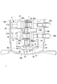
- FIG. 1 is a longitudinal sectional view of a hermetic compressor according to an embodiment of the present invention.
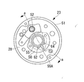
- FIG. 2 is an enlarged longitudinal sectional view of a main part of the hermetic compressor shown in FIG. 1. It is the top view which looked at the lower bearing of the hermetic compressor shown in Drawing 2 from the lower part.
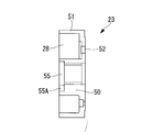
- FIG. 4 is a cross-sectional view corresponding to aa of the lower bearing shown in FIG. 3. It is a cross-sectional view of the oil supply pump part of the hermetic compressor shown in FIG.
- FIG. 1 is a longitudinal sectional view of a hermetic compressor 1 according to an embodiment of the present invention.
- a low-stage two-cylinder rotary compressor that constitutes the first compressor 2 is disposed in the lower portion of the hermetic housing 10, and a high-stage scroll compressor that constitutes the second compressor 3 in the upper portion.
- the hermetic compressor 1 according to the present invention will be described by taking a hermetic multistage compressor provided with an example as an example.
- the present invention is not limited to this, and the first compressor 2 is a single-cylinder rotary compressor.
- the second compressor 3 does not need to be a scroll compressor, and may be a compressor of another type.
- the hermetic compressor (sealed multistage compressor) 1 includes a hermetic housing 10.
- the sealed housing 10 includes a cylindrical center housing 10A, an annular bearing bracket 11 provided by welding all around the center housing 10A, a lower housing 10B that seals the lower portion of the center housing 10A, and the bearing bracket 11
- the upper housing 10C is provided at the upper portion by welding all around and seals the upper portion of the center housing 10A.
- An electric motor 4 including a stator 5 and a rotor 6 is fixedly installed at a substantially central portion in the center housing 10A.
- a rotating shaft (crankshaft) 7 is integrally coupled to the rotor 6.
- a low-stage two-cylinder rotary compressor 2 constituting the first compressor 2 is installed below the electric motor 4, a low-stage two-cylinder rotary compressor 2 constituting the first compressor 2 is installed.
- the two-cylinder rotary compressor 2 includes cylinder chambers 20A and 20B.
- the cylinder main bodies 21A and 21B are fixedly installed in the center housing 10A, and are fixedly installed on the upper part of the cylinder main body 21A and the lower part of the cylinder main body 21B.
- the two-cylinder rotary compressor 2 sucks a low-pressure refrigerant gas (working gas) into the cylinder chambers 20A and 20B via the suction pipes 26A and 26B, and this refrigerant gas is rotated by the rotors 25A and 25B to an intermediate pressure.
- refrigerant gas working gas
- This refrigerant gas is rotated by the rotors 25A and 25B to an intermediate pressure.
- This intermediate-pressure refrigerant gas flows through a gas passage hole (not shown) provided in the rotor 6 of the electric motor 4 and is guided to the upper space of the electric motor 4, and further the high-pressure refrigerant gas constituting the second compressor 3. It is sucked into the stage side scroll compressor 3 and compressed by two stages.
- the high-stage scroll compressor 3 constituting the second compressor 3 is provided in the upper housing 10C.
- the scroll compressor 3 is provided with a bearing 30 that supports a rotating shaft (crankshaft) 7, and a bearing case 31 (also referred to as a frame member or a supporting member) fixedly installed on the upper surface of the bearing bracket 11 via bolts 12.
- a bearing case 31 also referred to as a frame member or a supporting member
- the spiral wraps 32B and 33B standing on the end plates 32A and 33A, respectively, and the spiral wraps 32B and 33B are engaged with each other and assembled on the bearing case 31 to constitute a pair of compression chambers 34.
- a fixed scroll member 32 and an orbiting scroll member 33 are provided.
- the scroll compressor 3 further couples the orbiting scroll member 33 and the eccentric pin 7C of the rotating shaft 7 via the drive bush 13 to rotate the orbiting scroll member 33 so as to revolve and drive, and the orbiting scroll member 33.
- a rotation prevention mechanism 35 that is provided between the bearing case 31 and prevents the rotation of the orbiting scroll member 33 to rotate and revolves, and a discharge reed valve 36 that is provided on the back side of the fixed scroll member 32 and opens and closes the discharge port 32C.
- a fixed cover so as to surround the discharge reed valve 36 on the back side of the fixed scroll member 32, a discharge cover 38 forming an oil separation chamber 37, and a compressed high-pressure gas connected to the center of the discharge cover 38 Is installed in the oil separation chamber 37 and the discharge pipe 39 for discharging the oil to the outside, and the oil is centrifuged from the compressed gas.
- the oil separation mechanism 40 configured to include a.
- the scroll compressor 3 sucks the intermediate-pressure refrigerant gas compressed by the two-cylinder rotary compressor 2 and discharged into the sealed housing 10 into the compression chamber 34. After being compressed to a higher pressure state by a compression operation by revolving turning drive, it is configured to discharge to the oil separation chamber 37 in the discharge cover 38 via the discharge reed valve 36.
- the high-temperature and high-pressure refrigerant gas is sent to the outside of the hermetic compressor 1, that is, to the refrigeration cycle side through the discharge pipe 39 after the oil in the gas is separated by the oil separation mechanism 40 in the oil separation chamber 37. It has become so.
- a positive displacement oil pump 14 is incorporated between the lowermost end of the rotary shaft (crankshaft) 7 and the lower bearing 23 of the low-stage rotary compressor 2.
- the oil pump 14 pumps up the lubricating oil 15 filled in the bottom of the hermetic housing 10, and through the oil holes 16 provided in the rotary shaft 7, the bearing portions of the two-cylinder rotary compressor 2 and the scroll compressor 3.
- the lubricating oil 15 is forcibly supplied to a required lubricating portion.
- the oil supplied by the oil supply pump 14 and lubricated the scroll compressor 3 and the oil separated by the oil separation mechanism 40 are oil drop holes 41 and 42 provided in the fixed scroll member 32 and the bearing case 31, respectively. , 43, the oil is discharged from an oil discharge pipe 44 connected to the bearing bracket 11 to the bottom of the hermetic housing 10. It is assumed that a pressure reduction mechanism (not shown) is interposed in the oil drain hole 41 from the oil separation mechanism 40.
- the lower bearing 23, the lower muffler chamber 28, and the oil supply pump 14 described above are configured as follows.
- the lower bearing 23 is provided with a bearing boss portion 50 that supports the shaft end of the rotating shaft (crankshaft) 7 at the center portion, and surrounds the bearing boss portion 50 on the outer periphery thereof.
- it is set as the double cylinder shape provided with the outer cylinder 51 with the lower part opened.
- An annular space formed between the bearing boss portion 50 of the lower bearing 23 and the outer cylinder 51 is configured as a lower muffler chamber 28.
- the lower bearing 23 is provided with a discharge port 52 that allows the cylinder chamber 20B and the lower muffler chamber 28 to communicate with each other.
- the discharge port 52 includes a leaf spring-like reed valve on the lower muffler chamber 28 side.
- a discharge valve 53 is installed.
- the lower bearing 23 is fixedly installed on the cylinder body 21 ⁇ / b> B by a plurality of bolts 54.
- a cylinder chamber 55 having a predetermined dimension in the axial direction constituting the oil supply pump 14 is formed concentrically with the rotary shaft 7 on the lower end surface of the bearing boss portion 50.
- the cylinder chamber 54 is provided with a blade groove 55A extending in the radial direction.
- the lower end surface of the bearing boss portion 50 in the lower bearing 23 and the lower end surface of the outer cylinder 51 are formed on the same plane, and the lower end surface includes a thin plate member 56 and a thick plate presser member 57.
- a flat lid member 58 is fixedly installed via a bolt 59. As a result, the lower muffler chamber 28 and the cylinder chamber 55 are covered and sealed with a common flat lid member 58.
- the cylinder chamber 55 defined by the lid member 58 is attached to an eccentric portion 7 ⁇ / b> D provided at the shaft end of the rotating shaft 7.
- a rotor 60 that is rotated on the inner peripheral surface is accommodated.
- a blade 60A that is slidably fitted in a blade groove 55A of the cylinder chamber 55 is integrally provided on the outer periphery of the rotor 60, and partitions the inside of the cylinder chamber 55 into a suction side and a discharge side of the lubricating oil.
- a suction port 62 communicating with a suction pipe 61 suspended in the lubricant 15 filled in the bottom of the sealed housing 10 is opened on the lubricant suction side of the cylinder chamber 55, and the lubricant discharge side
- a discharge port 64 communicating with an oil supply hole 16 provided in the rotary shaft 7 is opened through an oil passage 63 provided in the lid member 58.
- an oil supply pump 14 for forcibly supplying the lubricating oil 15 to the two-cylinder rotary compressor 2 and the scroll compressor 3 is configured.
- the oil passage 63 is provided on the mating surface of the plate member 56 and the plate pressing member 57 constituting the lid member 58 so as to communicate with the discharge port 64 and the oil supply hole 16.
- the discharge port 52 provided in the lower bearing 23 and the suction port 62, the discharge port 64 and the blade groove 55 ⁇ / b> A constituting the oil supply pump 14 provided in the bearing boss 50 are opposite to each other across the axis of the rotating shaft 7. (See FIG. 3).
- the outer diameter of the bearing boss portion 50 is increased to provide the suction port 62, the discharge port 64, and the blade groove 55A, and the radial space between the outer cylinder 51 and the rotary shaft 7 is reduced.
- the space between the bearing boss 50 and the outer cylinder 51 on the side where the discharge port 52 on the opposite side is provided across the shaft core can be widened. For this reason, the installation space of the discharge valve 53 comprised by a reed valve can fully be ensured.
- the low-temperature and low-pressure refrigerant gas sucked into the cylinder chambers 20A and 20B of the two-cylinder rotary compressor 2 constituting the first compressor 2 through the suction pipes 26A and 26B reaches the intermediate pressure by the rotation of the rotors 25A and 25B. After being compressed, the air is discharged into the upper muffler chamber 27 and the lower muffler chamber 28, and the pulsation is attenuated.
- the intermediate pressure refrigerant gas is merged in the upper muffler chamber 27 and then discharged into the lower space of the electric motor 4, from which gas passage holes (not shown) provided in the rotor 6 of the electric motor 4, etc. And flows into the upper space of the electric motor 4.
- the intermediate-pressure refrigerant gas that has flowed into the upper space of the electric motor 4 passes through a suction gas passage (not shown) formed between the outer surface of the bearing case 31 and the upper surface of the bearing bracket 11 from the center region of the center housing 10A. Then, the air is sucked into the compression chamber 34 formed between the fixed scroll member 32 and the orbiting scroll member 33.
- the intermediate-pressure refrigerant gas is compressed into a high-temperature and high-pressure state by a compression operation caused by the orbiting scroll member 33 being driven to revolve orbit, and then discharged into the discharge cover 38 from the discharge port 32C via the discharge reed valve 36. It is.
- part of the lubricating oil 15 supplied by the oil supply pump 14 and used for lubrication of the two-cylinder rotary compressor 2 dissolves in the refrigerant gas, and enters the center housing 10A together with the intermediate-pressure refrigerant gas. Vomited. Further, the intermediate pressure refrigerant gas is supplied to the scroll compressor 3 through the oil supply hole 16, lubricates the scroll compressor 3, and then passes through the oil drain holes 43 and 42 and the oil discharge pipe 44 to enter the sealed housing 10. Part of the lubricating oil 15 that flows down to the bottom of the melted.
- the intermediate pressure refrigerant gas in which the lubricating oil 15 is dissolved in this way is sucked into the scroll compressor 3 while containing the oil and compressed, becomes high-temperature high-pressure gas, and is discharged from the discharge port 32C together with the oil.
- the high-temperature and high-pressure compressed gas containing oil is connected to the center of the discharge cover 38 after the oil is centrifuged by a centrifugal oil separation mechanism 40 provided in an oil separation chamber 37 in the discharge cover 38.
- the discharge pipe 39 is discharged to the refrigeration cycle side.
- OCR oil circulation rate
- the oil separated in the oil separation chamber 37 is depressurized to a low pressure in the oil dropping hole 41 by a pressure reducing mechanism, and then flows down to the bottom in the sealed housing 10 through the oil dropping hole 42 and the oil discharge pipe 44.
- the lower bearing 23 provided with the cylinder chamber 55 of the oil pump 14 for supplying the lubricating oil 15 is formed in a double cylinder shape, and the cylinder chamber 55 is provided on the lower end surface of the bearing boss portion 50 formed at the center portion thereof.
- An annular lower muffler chamber 28 is provided between the bearing boss portion 50 and an outer cylinder 51 formed so as to surround the outer periphery thereof.
- the lower muffler chamber 28 and the cylinder chamber 55 are defined by forming the lower end surfaces of the bearing boss portion 50 and the outer cylinder 51 on the same plane and covering the lower end surfaces with a common flat lid member 58. .
- both the lower muffler chamber 28 and the cylinder chamber 55 can be defined by the double-cylindrical lower bearing 23 and the flat lid member 58.
- the number of components of the lower muffler chamber 28 and the oil pump 14 can be reduced, and the configuration can be simplified and the cost can be reduced. Since it is possible to process the lower end surface of the bearing boss portion 50 and the outer cylinder 51 and the flat surface processing of the flat lid member 58 attached to the lower end surface in one step, the lower bearing 23 and the lid The number of processing steps for the member 58 (the plate member 56 and the plate pressing member 57) can be reduced, and the productivity can be improved and the cost can be reduced.
- the lower muffler chamber 28 can be simply configured by the outer cylinder 51 of the lower bearing 23 having a double cylinder shape, it is not necessary to install a lower muffler part as a separate part. it can. As a result, the effective volume of the lower muffler chamber 28 can be ensured to the maximum, and the effect of reducing discharge pulsation can be enhanced.
- the positive displacement oil pump 14 is configured to send the lubricating oil 15 to the oil hole 16 formed in the rotating shaft 7, the minimum components using the lower bearing 23 and the lower end of the rotating shaft 7 are used.
- the oil supply pump 14 to the second compressor (scroll compressor) 3 disposed in the upper part of the hermetic housing 10 can be configured.
- both the lower muffler chamber 28 and the positive displacement oil pump 14 can be configured simply and inexpensively with a minimum number of parts.
- the hermetic compressor 1 of the present invention is not limited to one using an HFC refrigerant such as R410A as a working gas, but can be similarly applied to one using a CO2 refrigerant or another refrigerant.
- the first compressor 2 disposed in the lower portion of the hermetic housing 10 may be a single-cylinder rotary compressor. Even in this case, providing the lower muffler chamber 28 in the lower bearing 23 is effective in reducing the pressure loss during discharge.
- the oil supply pump 14 not only the thing of the said embodiment but of course, you may use the positive displacement pump of another type.
Landscapes
- Engineering & Computer Science (AREA)
- Mechanical Engineering (AREA)
- General Engineering & Computer Science (AREA)
- Applications Or Details Of Rotary Compressors (AREA)
Abstract
L'invention concerne un compresseur à carter fermé possédant des premier et second compresseurs disposés au niveau des parties supérieure et inférieure d'un boîtier fermé, avec le premier compresseur au niveau de la partie inférieure consistant en un compresseur rotatif. Le compresseur à carter fermé a une structure simplifiée et un coût réduit par réduction du nombre de pièces constituant la pompe d'alimentation en huile et la chambre de silencieux inférieure et par adaptation desdites pièces pour qu'elles soient aisément usinables. Dans un compresseur à carter fermé (1) possédant des premier et second compresseurs (2, 3) disposés au niveau des parties supérieure et inférieure d'un boîtier (10) fermé, avec le premier compresseur (2) au niveau de la partie inférieure consistant en un compresseur rotatif, un palier inférieur (23) du compresseur rotatif (2) supporte l'extrémité inférieure de l'arbre rotatif (7) au niveau du centre du palier inférieur, possède un bossage de palier (50) possédant au niveau de sa surface d'extrémité inférieure une chambre cylindrique (55) de la pompe d'alimentation en huile (14), et est en forme de double tube possédant un tube externe (51) situé sur le côté périphérique externe du bossage de palier (50) de manière à entourer ledit bossage. Un couvercle (58) est monté sur la surface d'extrémité inférieure du palier inférieur (23) afin de définir la chambre cylindrique (55) et la chambre de silencieux inférieure (82) du compresseur (2) rotatif.
Priority Applications (1)
| Application Number | Priority Date | Filing Date | Title |
|---|---|---|---|
| EP09705410.0A EP2253849B1 (fr) | 2008-01-29 | 2009-01-13 | Compresseur à carter fermé |
Applications Claiming Priority (2)
| Application Number | Priority Date | Filing Date | Title |
|---|---|---|---|
| JP2008018204A JP5276332B2 (ja) | 2008-01-29 | 2008-01-29 | 密閉型圧縮機 |
| JP2008-018204 | 2008-01-29 |
Publications (1)
| Publication Number | Publication Date |
|---|---|
| WO2009096220A1 true WO2009096220A1 (fr) | 2009-08-06 |
Family
ID=40912573
Family Applications (1)
| Application Number | Title | Priority Date | Filing Date |
|---|---|---|---|
| PCT/JP2009/050322 Ceased WO2009096220A1 (fr) | 2008-01-29 | 2009-01-13 | Compresseur à carter fermé |
Country Status (3)
| Country | Link |
|---|---|
| EP (1) | EP2253849B1 (fr) |
| JP (1) | JP5276332B2 (fr) |
| WO (1) | WO2009096220A1 (fr) |
Cited By (1)
| Publication number | Priority date | Publication date | Assignee | Title |
|---|---|---|---|---|
| JP2012202353A (ja) * | 2011-03-28 | 2012-10-22 | Daikin Industries Ltd | 圧縮要素および圧縮機 |
Families Citing this family (2)
| Publication number | Priority date | Publication date | Assignee | Title |
|---|---|---|---|---|
| CN105332888A (zh) * | 2014-07-22 | 2016-02-17 | 珠海格力节能环保制冷技术研究中心有限公司 | 压缩机及具有其的空调器 |
| CN105986987A (zh) * | 2015-02-12 | 2016-10-05 | 珠海格力节能环保制冷技术研究中心有限公司 | 压缩机及空调器 |
Citations (11)
| Publication number | Priority date | Publication date | Assignee | Title |
|---|---|---|---|---|
| JPH0272383U (fr) * | 1988-11-18 | 1990-06-01 | ||
| JPH0367094A (ja) * | 1989-08-07 | 1991-03-22 | Mitsubishi Electric Corp | 回転式圧縮機 |
| JPH0587074A (ja) | 1991-07-30 | 1993-04-06 | Mitsubishi Heavy Ind Ltd | 2段圧縮機 |
| JPH07103167A (ja) * | 1993-09-30 | 1995-04-18 | Mitsubishi Heavy Ind Ltd | 二段圧縮機 |
| JPH08200223A (ja) * | 1995-01-31 | 1996-08-06 | Daikin Ind Ltd | 圧縮機の油ポンプ装置 |
| JPH09151866A (ja) * | 1995-11-30 | 1997-06-10 | Sanyo Electric Co Ltd | スクロール圧縮機 |
| JPH109175A (ja) * | 1996-06-25 | 1998-01-13 | Mitsubishi Heavy Ind Ltd | 圧縮機の給油ポンプ装置 |
| JP2000087892A (ja) * | 1998-09-08 | 2000-03-28 | Daikin Ind Ltd | 2段圧縮機及び空気調和装置 |
| JP2002250292A (ja) * | 2001-02-22 | 2002-09-06 | Hitachi Ltd | 密閉型回転圧縮機及び冷凍・空調装置 |
| JP2006083842A (ja) | 2004-09-15 | 2006-03-30 | Samsung Electronics Co Ltd | 多気筒圧縮機 |
| JP2007177624A (ja) | 2005-12-27 | 2007-07-12 | Mitsubishi Electric Corp | 2気筒回転式密閉型圧縮機及び2気筒回転式密閉型圧縮機の製造方法 |
Family Cites Families (1)
| Publication number | Priority date | Publication date | Assignee | Title |
|---|---|---|---|---|
| US20090241581A1 (en) * | 2005-10-31 | 2009-10-01 | Matsushita Electric Industrial Co., Ltd. | Expander and heat pump using the expander |
-
2008
- 2008-01-29 JP JP2008018204A patent/JP5276332B2/ja active Active
-
2009
- 2009-01-13 EP EP09705410.0A patent/EP2253849B1/fr active Active
- 2009-01-13 WO PCT/JP2009/050322 patent/WO2009096220A1/fr not_active Ceased
Patent Citations (11)
| Publication number | Priority date | Publication date | Assignee | Title |
|---|---|---|---|---|
| JPH0272383U (fr) * | 1988-11-18 | 1990-06-01 | ||
| JPH0367094A (ja) * | 1989-08-07 | 1991-03-22 | Mitsubishi Electric Corp | 回転式圧縮機 |
| JPH0587074A (ja) | 1991-07-30 | 1993-04-06 | Mitsubishi Heavy Ind Ltd | 2段圧縮機 |
| JPH07103167A (ja) * | 1993-09-30 | 1995-04-18 | Mitsubishi Heavy Ind Ltd | 二段圧縮機 |
| JPH08200223A (ja) * | 1995-01-31 | 1996-08-06 | Daikin Ind Ltd | 圧縮機の油ポンプ装置 |
| JPH09151866A (ja) * | 1995-11-30 | 1997-06-10 | Sanyo Electric Co Ltd | スクロール圧縮機 |
| JPH109175A (ja) * | 1996-06-25 | 1998-01-13 | Mitsubishi Heavy Ind Ltd | 圧縮機の給油ポンプ装置 |
| JP2000087892A (ja) * | 1998-09-08 | 2000-03-28 | Daikin Ind Ltd | 2段圧縮機及び空気調和装置 |
| JP2002250292A (ja) * | 2001-02-22 | 2002-09-06 | Hitachi Ltd | 密閉型回転圧縮機及び冷凍・空調装置 |
| JP2006083842A (ja) | 2004-09-15 | 2006-03-30 | Samsung Electronics Co Ltd | 多気筒圧縮機 |
| JP2007177624A (ja) | 2005-12-27 | 2007-07-12 | Mitsubishi Electric Corp | 2気筒回転式密閉型圧縮機及び2気筒回転式密閉型圧縮機の製造方法 |
Non-Patent Citations (1)
| Title |
|---|
| See also references of EP2253849A4 * |
Cited By (1)
| Publication number | Priority date | Publication date | Assignee | Title |
|---|---|---|---|---|
| JP2012202353A (ja) * | 2011-03-28 | 2012-10-22 | Daikin Industries Ltd | 圧縮要素および圧縮機 |
Also Published As
| Publication number | Publication date |
|---|---|
| EP2253849A4 (fr) | 2015-05-06 |
| JP5276332B2 (ja) | 2013-08-28 |
| JP2009180108A (ja) | 2009-08-13 |
| EP2253849B1 (fr) | 2018-02-21 |
| EP2253849A1 (fr) | 2010-11-24 |
Similar Documents
| Publication | Publication Date | Title |
|---|---|---|
| AU776646B2 (en) | Horizontal scroll compressor | |
| EP2177768A1 (fr) | Compresseur à plusieurs étages | |
| JP5232595B2 (ja) | 多段圧縮機 | |
| JP5781019B2 (ja) | ロータリ式圧縮機 | |
| US8118563B2 (en) | Tandem compressor system and method | |
| JP5244407B2 (ja) | 密閉型スクロール圧縮機及びその製造方法 | |
| JP5112090B2 (ja) | スクロール圧縮機 | |
| JP5276332B2 (ja) | 密閉型圧縮機 | |
| JP4306771B2 (ja) | 圧縮機 | |
| EP1947292B1 (fr) | Machine à fluide ayant un vilebrequin | |
| US7866962B2 (en) | Two-stage rotary compressor | |
| EP2685106B1 (fr) | Compresseur à deux étages et système de compression à deux étages | |
| KR101015016B1 (ko) | 스크롤 압축기 | |
| JP5999922B2 (ja) | スクロール圧縮機 | |
| KR200382995Y1 (ko) | 복식 로터리 압축기용 어큐뮬레이터 | |
| KR200382914Y1 (ko) | 복식 로터리 압축기의 어큐뮬레이터 구조 | |
| US20250101976A1 (en) | Scroll compressor | |
| WO2013015215A1 (fr) | Machine à fluide | |
| KR20250044559A (ko) | 스크롤 압축기 | |
| JP2012219700A (ja) | 多段圧縮機 | |
| JPH1061572A (ja) | 横置スクロール圧縮機 |
Legal Events
| Date | Code | Title | Description |
|---|---|---|---|
| 121 | Ep: the epo has been informed by wipo that ep was designated in this application |
Ref document number: 09705410 Country of ref document: EP Kind code of ref document: A1 |
|
| WWE | Wipo information: entry into national phase |
Ref document number: 2009705410 Country of ref document: EP |
|
| NENP | Non-entry into the national phase |
Ref country code: DE |