WO2009096232A1 - Dispositif et procédé de traitement d'image - Google Patents
Dispositif et procédé de traitement d'image Download PDFInfo
- Publication number
- WO2009096232A1 WO2009096232A1 PCT/JP2009/050453 JP2009050453W WO2009096232A1 WO 2009096232 A1 WO2009096232 A1 WO 2009096232A1 JP 2009050453 W JP2009050453 W JP 2009050453W WO 2009096232 A1 WO2009096232 A1 WO 2009096232A1
- Authority
- WO
- WIPO (PCT)
- Prior art keywords
- spectral
- imaging
- matrix
- illumination
- subject
- Prior art date
- Legal status (The legal status is an assumption and is not a legal conclusion. Google has not performed a legal analysis and makes no representation as to the accuracy of the status listed.)
- Ceased
Links
Images


Classifications
-
- G—PHYSICS
- G01—MEASURING; TESTING
- G01J—MEASUREMENT OF INTENSITY, VELOCITY, SPECTRAL CONTENT, POLARISATION, PHASE OR PULSE CHARACTERISTICS OF INFRARED, VISIBLE OR ULTRAVIOLET LIGHT; COLORIMETRY; RADIATION PYROMETRY
- G01J3/00—Spectrometry; Spectrophotometry; Monochromators; Measuring colours
- G01J3/28—Investigating the spectrum
-
- G—PHYSICS
- G03—PHOTOGRAPHY; CINEMATOGRAPHY; ANALOGOUS TECHNIQUES USING WAVES OTHER THAN OPTICAL WAVES; ELECTROGRAPHY; HOLOGRAPHY
- G03B—APPARATUS OR ARRANGEMENTS FOR TAKING PHOTOGRAPHS OR FOR PROJECTING OR VIEWING THEM; APPARATUS OR ARRANGEMENTS EMPLOYING ANALOGOUS TECHNIQUES USING WAVES OTHER THAN OPTICAL WAVES; ACCESSORIES THEREFOR
- G03B33/00—Colour photography, other than mere exposure or projection of a colour film
- G03B33/06—Colour photography, other than mere exposure or projection of a colour film by additive-colour projection apparatus
-
- H—ELECTRICITY
- H04—ELECTRIC COMMUNICATION TECHNIQUE
- H04N—PICTORIAL COMMUNICATION, e.g. TELEVISION
- H04N23/00—Cameras or camera modules comprising electronic image sensors; Control thereof
- H04N23/80—Camera processing pipelines; Components thereof
- H04N23/84—Camera processing pipelines; Components thereof for processing colour signals
- H04N23/88—Camera processing pipelines; Components thereof for processing colour signals for colour balance, e.g. white-balance circuits or colour temperature control
-
- G—PHYSICS
- G01—MEASURING; TESTING
- G01J—MEASUREMENT OF INTENSITY, VELOCITY, SPECTRAL CONTENT, POLARISATION, PHASE OR PULSE CHARACTERISTICS OF INFRARED, VISIBLE OR ULTRAVIOLET LIGHT; COLORIMETRY; RADIATION PYROMETRY
- G01J3/00—Spectrometry; Spectrophotometry; Monochromators; Measuring colours
- G01J3/46—Measurement of colour; Colour measuring devices, e.g. colorimeters
- G01J2003/467—Colour computing
Definitions
- the present invention relates to an image processing apparatus and an image processing method capable of calculating the spectral radiance of illumination light applied to a subject when the subject is imaged.
- a color management technique based on the spectral reflectance (reflection spectrum) of a subject is known. This technique is realized by handling the color of the subject in the wavelength region, and enables accurate color reproduction regardless of the illumination environment of the subject.
- An imaging method based on the spectral reflectance of such a subject is disclosed in “Yoichi Miyake,“ Introduction to Spectral Image Processing ”, The University of Tokyo Press, February 24, 2006”. Has been.
- the spectral radiance from the subject is determined in accordance with the spectral radiance of the illumination light and the spectral reflectance of the subject, so if the spectral radiance of the illumination light is not known, imaging data obtained by imaging the subject This is because the spectral reflectance of the subject cannot be accurately calculated based on the above.
- the spectral radiance of the illumination light is also used for white balance adjustment of the imaging device.
- This white balance adjustment is an operation for determining a coefficient for mutually adjusting the levels of luminance values output from a plurality of image sensors constituting the imaging apparatus.
- white balance adjustment is disclosed in Japanese Patent Application Laid-Open Nos. 2001-057680 and 2005-328386.
- Japanese Patent Laid-Open No. 2001-056780 JP 2005-328386 A Yoichi Miyake, “Introduction to Spectral Image Processing”, The University of Tokyo Press, February 24, 2006
- the spectral radiance of illumination light has been measured exclusively using a dedicated measuring device such as a spectroradiometer.
- a spectroradiometer separates light incident through an optical system with a diffraction grating (grating), and receives the light with an image sensor (CCD (Charge Coupled Device), CMOS (Complementary Metal Oxide Semiconductor), etc.) for each wavelength. Get the brightness value of. If it is going to implement
- CCD Charge Coupled Device
- CMOS Complementary Metal Oxide Semiconductor
- the present invention has been made to solve such a problem, and an object of the present invention is to easily reduce the spectral radiance of illumination light applied to the subject using an imaging device for imaging the subject. It is to provide an image processing apparatus and an image processing method that can be calculated.
- an image processing device capable of performing image processing on imaging data imaged by an imaging device.
- the image processing apparatus uses an imaging device to receive first imaging data obtained by imaging at least a part of light incident on a subject through a diffusing member in an illumination environment, and an illumination unit Using the first estimation matrix calculated based on the autocorrelation matrix of the spectral radiance of the light source candidates that can be used to provide the environment, the spectral transmittance of the diffusing member, and the spectral sensitivity of the imaging device, A first calculator that calculates the spectral radiance of the illumination light incident on the subject from the first imaging data.
- the spectral radiance of the light source candidate is a characteristic value acquired in advance for each type of light source.
- the diffusing member is disposed on the optical axis of the imaging apparatus, and the incident intensity of the diffusing member is indicated by a predetermined function value with respect to an angle with respect to the optical axis.
- the function value is a cosine function with respect to an angle with respect to the optical axis.
- the imaging device is configured to output coordinate values defined in the RGB color system as imaging data.
- the image processing apparatus uses a spectral radiance of the illumination light and a color matching function to calculate a coordinate value in the RGB color system corresponding to the spectral radiance of the illumination light, and a second calculator And a third calculation unit that calculates white balance in the imaging apparatus based on the calculated ratio of coordinate values.
- the image processing apparatus has a second estimation matrix calculated based on the spectral radiance of the illumination light, the spectral sensitivity of the imaging apparatus, and the autocorrelation matrix of the spectral reflectance of colors that can be included in the subject.
- a fourth calculation unit that calculates the spectral reflectance of the subject from the second imaging data obtained by imaging the subject with the imaging device in an illumination environment.
- the image processing device includes a generation unit that generates image data acquired when the subject is imaged under a predetermined illumination environment based on the spectral reflectance of the subject calculated by the fourth calculation unit. In addition.
- an image processing device capable of image processing with respect to imaging data imaged by an imaging device.
- the image processing apparatus uses an imaging device to receive first imaging data obtained by imaging at least a part of light incident on a subject through a diffusing member in an illumination environment, and an illumination unit A selection unit that selects one of the predetermined calculation matrices for each type of a plurality of light source candidates that can be used to provide an environment according to an external command, a calculation matrix selected by the selection unit, A first calculation for calculating the spectral radiance of the illumination light incident on the subject from the first imaging data using the first estimation matrix calculated based on the spectral transmittance of the diffusing member and the spectral sensitivity of the imaging device.
- Each of the calculation matrices is an autocorrelation matrix of a matrix indicating the spectral radiance of the light source candidate.
- an image processing apparatus capable of performing image processing on imaging data captured by an imaging apparatus.
- the image processing apparatus uses an imaging device to receive first imaging data obtained by imaging at least a part of light incident on a subject through a diffusing member in an illumination environment, and an illumination unit A selection unit that selects one of a plurality of first estimation matrices according to an external command, which is calculated in advance based on spectral radiances of a plurality of light source candidates that can be used to provide an environment, and a selection unit And a first calculator that calculates the spectral radiance of the illumination light incident on the subject from the first imaging data using the selected first estimation matrix.
- the first estimation matrix is calculated based on the autocorrelation matrix of the matrix indicating the spectral radiance of the corresponding light source candidate, the spectral transmittance of the diffusing member, and the spectral sensitivity of the imaging device.
- an image processing apparatus capable of performing image processing on imaging data captured by an imaging apparatus.
- the image processing apparatus uses an imaging device to receive first imaging data obtained by imaging at least a part of light incident on a subject through a diffusing member in an illumination environment, and an illumination unit The spectral radiance of illumination light incident on the subject from the first imaging data using a plurality of first estimation matrices respectively calculated based on the spectral radiances of a plurality of light source candidates that can be used to provide an environment
- a first calculation unit for calculating each candidate and each calculated spectral radiance candidate are evaluated by comparison with a predetermined reference pattern, and one of them is output as the spectral radiance of illumination light in an illumination environment.
- the first estimation matrix is calculated based on the autocorrelation matrix of the matrix indicating the spectral radiance of the corresponding light source candidate, the spectral transmittance of the diffusing member, and the spectral sensitivity of the imaging device.
- the image processing method is a step of acquiring first imaging data by imaging at least part of light incident on a subject under a lighting environment through a diffusing member using an imaging device.
- a first estimation matrix calculated based on the autocorrelation matrix of spectral radiance of light source candidates that can be used to provide an illumination environment, the spectral transmittance of the diffusing member, and the spectral sensitivity of the imaging device And calculating the spectral radiance of the illumination light incident on the subject from the first imaging data.
- the image processing method is a step of acquiring first imaging data by imaging at least part of light incident on a subject under a lighting environment through a diffusing member using an imaging device. Selecting one of a plurality of predetermined calculation matrices for each type of light source candidates that can be used to provide an illumination environment, the selected calculation matrix, and spectral transmission of the diffusing member Calculating the spectral radiance of the illumination light incident on the subject from the first imaging data using a first estimation matrix calculated based on the rate and the spectral sensitivity of the imaging device.
- Each of the calculation matrices is an autocorrelation matrix of a matrix indicating the spectral radiance of the light source candidate.
- the image processing method is a step of acquiring first imaging data by imaging at least part of light incident on a subject under a lighting environment through a diffusing member using an imaging device. Selecting one of a plurality of first estimation matrices calculated in advance based on spectral radiances of a plurality of light source candidates that can be used to provide an illumination environment, and the selected first estimation matrix And calculating the spectral radiance of the illumination light incident on the subject from the first imaging data.
- the first estimation matrix is calculated based on the autocorrelation matrix of the matrix indicating the spectral radiance of the corresponding light source candidate, the spectral transmittance of the diffusing member, and the spectral sensitivity of the imaging device.
- the image processing method is a step of acquiring first imaging data by imaging at least part of light incident on a subject under a lighting environment through a diffusing member using an imaging device. And using the plurality of first estimation matrices calculated based on the spectral radiances of the plurality of light source candidates that can be used to provide the illumination environment, the spectrum of the illumination light incident on the subject from the first imaging data
- Each radiance candidate calculation step is evaluated by comparing each calculated spectral radiance candidate with a predetermined reference pattern, one of which is output as the spectral radiance of the illumination light in the illumination environment Including the step of.
- the first estimation matrix is calculated based on the autocorrelation matrix of the matrix indicating the spectral radiance of the corresponding light source candidate, the spectral transmittance of the diffusing member, and the spectral sensitivity of the imaging device.
- the present invention it is possible to easily calculate the spectral radiance of the illumination light applied to the subject using the imaging device for imaging the subject.
- FIG. 1 is a functional configuration diagram of an image processing device according to a first embodiment of the present invention. It is a figure for demonstrating the acquisition method of the imaging data used as the process target in the image processing apparatus according to Embodiment 1 of this invention. It is a figure for demonstrating the production
- Ax1, Ax2 optical axis, OBJ subject 1, 1A, 1B image processing device, 10, 20 input unit, 11, 11A, 11B, 11C, 11D spectral radiance calculation unit, 12 estimation matrix calculation unit, 13, 13A light source data Storage unit, 14 Tristimulus value conversion unit, 15 Coordinate conversion unit, 16 White balance calculation unit, 17 Estimation matrix storage unit, 18 Selection unit, 19 Evaluation unit, 21 Spectral reflectance calculation unit, 22 Estimation matrix calculation unit, 23 Spectroscopy Reflectance data storage unit, 24 image data generation unit, 25 coordinate conversion unit, 100, 100A, 100B, 100C illumination spectrum estimation unit, 150 computer body, 152 monitor, 154 keyboard, 156 mouse, 162 memory, 164 fixed disk, 166 FD drive, 168 CD-ROM drive 170 communication interface, 200-color reproduction unit, 300 light source, 400 an imaging device, 402 diffusing member.
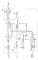
- FIG. 1 is a functional configuration diagram of an image processing apparatus 1 according to the first embodiment of the present invention.
- the image processing apparatus 1 includes first imaging data g (1) RGB (m, n) and second imaging data g (2) RGB (m, n) captured by an imaging apparatus described later.
- the image processing method according to the present embodiment can be executed.
- the image processing apparatus 1 includes an illumination spectrum estimation unit 100 and a color reproduction unit 200.
- the illumination spectrum estimation unit 100 calculates the spectral radiance E (1) (illumination spectrum) of the illumination light incident on the subject using the first imaging data g (1) RGB (m, n).
- the color reproduction unit 200 calculates the spectral reflectance of the subject from the second imaging data g (2) RGB (m, n) using the calculated spectral radiance E (1) .
- the color reproduction unit 200 outputs image data g (OUT) RGB (m, n) obtained by performing color reproduction of the subject based on the calculated spectral reflectance of the subject.
- the image data g (OUT) RGB (m, n) output from the color reproduction unit 200 is typically output to an output device (not shown) such as a display device (display) or a printing device (printer). Alternatively, it may be stored in a storage device (not shown).
- an output device such as a display device (display) or a printing device (printer).
- the image processing apparatus 1 is typically realized by hardware, but a part or all of the image processing apparatus 1 may be realized by software as will be described later.
- FIG. 2 is a diagram for describing a method for acquiring imaging data to be processed in image processing apparatus 1 according to the first embodiment of the present invention.
- FIG. 2 shows a case where the subject OBJ is imaged under a predetermined illumination environment.
- 2A shows a procedure for acquiring the first imaging data g (1) RGB (m, n)
- FIG. 2B shows the second imaging data g (2) RGB (m, n). The procedure to acquire is shown.
- the imaging device 400 is used for acquisition (imaging) of imaging data.
- the imaging apparatus 400 is a digital still camera or a digital video camera, and includes an imaging element (typically, CCD, CMOS, etc.) having spectral sensitivity characteristics in a specific wavelength band.
- the imaging element includes a plurality of pixels arranged in a matrix, and outputs luminance corresponding to the intensity of light incident on each pixel as imaging data.
- the luminance output from each image sensor has a value corresponding to the spectral sensitivity.
- a specific wavelength band that can be imaged by the imaging apparatus is referred to as a band.
- the imaging device 400 A case of using the imaging device 400 will be described.
- the device structure either a structure in which a plurality of types of image sensors are formed on the same substrate or a structure in which a corresponding type of image sensor is formed on a plurality of substrates can be adopted.
- the spectral sensitivity of the element itself may be made different, or an element having the same spectral sensitivity is used, and R, G are input to the input light side of each element.
- B may be provided.
- the imaging data output by the imaging apparatus 400 is three-dimensional color information of R, G, and B luminance values (typically, each of 12 bits: 0 to 4095 gradations).
- the imaging data output by the imaging apparatus 400 is defined in the RGB color system.
- (m, n) of the imaging data g (1) RGB (m, n), g (2) RGB (m, n) represents the coordinates of the corresponding pixel in the imaging device of the imaging device 400.
- the imaging data g (1) RGB (m, n), g (2) RGB (m, n) [(the luminance value detected by the R imaging element at coordinates (m, n)), (coordinate ( (luminance value detected by G image sensor at m, n)), (luminance value detected by B image sensor at coordinates (m, n))].
- illumination light emitted from some light source 300 is irradiated on the subject OBJ.
- the imaging device 400 is used to enter the subject OBJ from the light source 300.
- the light obtained through the diffusing member 402 that is, the light after passing through the diffusing member 402 is imaged at least part of the light to be transmitted.
- the optical axis Ax1 is on any path on which the illumination light enters the subject OBJ.
- a device 400 is arranged.
- a diffusing member 402 is disposed between the imaging device 400 and the light source 300 on this optical axis Ax1 (preferably in the immediate vicinity of the imaging device 400).
- the path of illumination light incident on the subject OBJ includes a path directly incident on the subject OBJ from the light source 300 and a path incident on the subject OBJ after being reflected from the light source 300 by a wall material or the like.
- the diffusion member 402 is a member for spatially diffusing the light imaged by the imaging device 400, that is, for spatially averaging, and a milky white diffusion plate having a known spectral transmittance is typically used. Alternatively, an integrating sphere or the like may be used. By using such a diffusing member 402, the intensity distribution of the illumination light incident on the imaging device 400 can be made uniform, thereby increasing the estimation accuracy of the spectral radiance of the illumination light described later.
- a diffusion plate having a predetermined incident angle characteristic (generally referred to as a cosine collector, a cosine diffuser, a cosine receptor, or the like).
- a cosine collector a cosine collector
- a cosine diffuser a cosine receptor
- the incident intensity of light after passing through the diffusing member 402 is indicated by a cosine function (cosine) with respect to an angle (solid angle) with respect to the optical axis Ax1 of the imaging device 400.
- the first imaging data g (1) RGB (m, n) acquired according to the above procedure includes color information reflecting illumination light incident on the subject OBJ under the illumination environment.
- the second imaging data g (2) RGB (m, n) is obtained by imaging the subject OBJ using the same imaging device 400 as in FIG. To be acquired.
- the diffusing member 402 is not disposed on the optical axis Ax2 of the imaging device 400.
- the imaging device 400 used for acquiring the first imaging data g (1) RGB (m, n) and the imaging device 400 used for acquiring the second imaging data g (2) RGB (m, n). are not necessarily the same, and different imaging devices 400 may be used as long as at least the spectral sensitivity of the imaging device is substantially known.
- the optical axis Ax1 of the imaging device 400 when imaging the first imaging data g (1) RGB (m, n), and the second imaging data g (2) in FIG. 2B It is preferable to match the optical axis Ax2 of the imaging device 400 when imaging RGB (m, n).
- the second imaging data g (2) RGB (m, n) acquired in FIG. 2B is determined mainly depending on the reflected light from the subject OBJ. This reflected light is reflected by the subject OBJ and propagates in the opposite direction on the optical axis Ax2, and the illumination light that generates this reflected light is mainly directed toward the subject OBJ on the optical axis Ax2 of the imaging device 400. Propagate. Therefore, by capturing the illumination light that generates the reflected light as the first imaging data g (1) RGB (m, n), a more appropriate spectral radiance of the illumination light can be calculated.
- the spectral radiance E (1) (illumination spectrum) of the illumination light incident on the subject executed by the illumination spectrum estimation unit 100 will be described.
- the spectral radiance E (1) of the illumination light should originally be a continuous function with respect to the wavelength ⁇ , but in the present embodiment, the spectral radiance E (1) is represented as a visible light region (380 to For 780 nanometers), discrete values sampled with a predetermined wavelength width (1 nanometer width) shall be used.
- a matrix In the matrix indicating the spectral radiance E (1) , the luminance value at each wavelength is set in the diagonal element, and zero is set in elements other than the diagonal element.
- the illumination spectrum estimation unit 100 includes an input unit 10, a spectral radiance calculation unit 11, an estimation matrix calculation unit 12, and a light source data storage unit 13.
- the input unit 10 is obtained by imaging at least a part of light incident on the subject OBJ through the diffusing member 402 using an imaging device 400 in an illumination environment.
- First imaging data g (1) RGB (m, n) is received. Further, the input unit 10 based on the first image data g (1) RGB (m, n) , the first imaging data g (1) RGB (m, n) image pickup data g (1) representing the RGB Is output.
- the imaging data g (1) RGB is linearized color data composed of three luminance values (representative values) of R, G, and B.
- the input unit 10 the first imaging data g (1) RGB (m, n) includes logic for averaging the luminance value included in the first imaging data g (1) RGB (m, n ) Is averaged separately for each of R, G, and B, and the averaged value (R, G, B) is output as imaging data g (1) RGB .
- the input unit 10 performs processing for canceling the inverse gamma characteristic.
- the first imaging data g (1) RGB (m, n) may be linearized.
- a display device has a non-linear relationship (gamma characteristic) between an input signal level and an actually displayed luminance level.
- the imaging device 400 has a non-linearity (inverse gamma characteristic) opposite to the gamma characteristic of the display device so that an image adapted to human vision is displayed by canceling such non-linearity in the display device.
- imaging data is often output.
- Imaging data g (1) RGB (m, n) is generated.
- the gamma characteristic and the inverse gamma characteristic can be expressed as a power function.
- the first imaging data g (1) RGB (m, n) can be linearized according to the following arithmetic expression.
- This lookup table is a data table in which the result of the above-described conversion formula is stored in advance in association with each of all the luminance values that can be taken by the input imaging data. Refer to the correspondence between this input and output. Since the converted value can be acquired simply by doing this, the amount of calculation can be greatly reduced.
- the spectral radiance calculation unit 11 uses the first estimation matrix W (1) calculated by the estimation matrix calculation unit 12 to be described later, and the spectral radiance of illumination light incident on the subject OBJ from the imaging data g (1) RGB. E (1) is calculated. More specifically, the spectral radiance calculation unit 11 calculates the spectral radiance E (1) of the illumination light based on the matrix product of the first estimation matrix W (1) and the imaging data g (1) RGB .
- the spectral radiance E (1) of 401 rows ⁇ 401 columns sampled with a predetermined wavelength width is used, so the first estimation matrix W ( 1) is the number of wavelength components ⁇ the number of bands of the imaging device 400, that is, a matrix of 401 rows ⁇ 3 columns.
- the estimation matrix calculation unit 12 includes the autocorrelation matrix B of the spectral radiance of the light source candidates that can be used to provide the illumination environment in the subject OBJ, the spectral transmittance f (1) of the diffusing member 402, and the spectral of the imaging device 400. Based on the sensitivity S, a first estimation matrix W (1) is calculated.
- the spectral sensitivity S is a matrix of 401 rows ⁇ 3 columns
- the spectral transmittance f (1) is a matrix of 401 rows ⁇ 3 columns.
- the light (spectrum) that has passed through the diffusing member 402 incident on the imaging device 400 includes the spectral radiance E (1) ( ⁇ ) of the illumination light applied to the diffusing member 402 (or the subject OBJ), and the diffusing member.
- the spectral transmittance f (1) ( ⁇ ) of the diffusing member 402 is assumed to be constant over the entire diffusing member 402.
- Such a relationship can be expressed as a relational expression shown in Expression (1).
- n i (m, n) is additive noise generated by white noise or the like appearing in each image sensor, and is a value depending on the characteristics of the image sensor and the lens of the imaging apparatus 400, the illumination environment, and the like.
- a matrix arithmetic expression sampled with a predetermined wavelength width (typically 1 nanometer width) is used. That is, the integral expression of the first term on the right side of the equation (1) is expressed by the spectral sensitivity S that is a matrix indicating the sensitivity at each wavelength of each image sensor and the spectral radiance E 1 that is a matrix indicating the radiance at each wavelength. ) And spectral transmittance f (1) which is a matrix indicating the transmittance at each wavelength.
- the spectral sensitivity S and the spectral transmittance f (1) are already known.
- the additive noise n i (m, n) is generally a sufficiently small value, and therefore, if ignored from the expression (1), the following matrix operation expression can be derived from the expression (1).
- W (1) W (1) ⁇ g (1) (3)
- W (1) is a first estimation matrix.
- the first estimation matrix W (1) is calculated by the winner estimation method described below. Specifically, the first estimation matrix W (1) is derived as shown in equation (5) by modifying the equation (2) after defining the system matrix I as the following equation (4).
- B is an autocorrelation matrix (hereinafter also referred to as “calculation matrix”) of spectral radiances of light source candidates that can be used to provide an illumination environment.
- spectral radiance for a plurality of light source candidates is acquired in advance, and from a statistical viewpoint, the spectral radiance of illumination light is used by utilizing the correlation with the spectral radiance of each light source.
- E (1) is estimated. That is, statistical data acquired for each type of light source is prepared in advance, and the spectral radiance E (1) of illumination light is calculated according to the characteristics of the statistical data.
- the autocorrelation matrix B of the spectral radiance serves as a reference for estimating the spectral radiance E (1) of the illumination light
- the type of the light source that is likely to be used to provide the illumination environment For example, it is preferable to use appropriate statistical data according to the light emission principle of fluorescent lamps, incandescent lamps, xenon lamps, mercury lamps, and the like.
- the spectral radiance of such a light source can be obtained experimentally in advance for each light source, or standardized by the International Commission on Illumination (CIE), ISO (International Organization for Standardization), or JIS (Japan Industrial Standards). Statistical data may be used.
- CIE International Commission on Illumination
- ISO International Organization for Standardization
- JIS Japan Industrial Standards
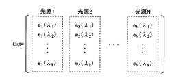
- FIG. 3 is a diagram for describing processing for generating an autocorrelation matrix B of spectral radiance according to the first embodiment of the present invention.
- a light source group matrix Est is generated with spectral radiance values of at least one type of light source candidates (light source 1 to light source N) as elements. That is, assuming that the component value (radiance) at each sampling wavelength ⁇ j (1 ⁇ j ⁇ k) of the light source i (1 ⁇ i ⁇ N) is e i ( ⁇ j ), the component value e i ( ⁇ Create a light source group matrix Est with j ) arranged in the row direction.
- an autocorrelation matrix B is calculated based on the group matrix Est according to the following arithmetic expression.
- a group matrix E st having the same sampling interval (number of elements ) is calculated. It is necessary to use it. Accordingly, a group matrix Est in which n matrixes of 401 rows ⁇ 1 column indicating the spectral radiance of one light source are combined is a 401 row ⁇ n column matrix, and the autocorrelation matrix of the group matrix Est is , 401 rows ⁇ 401 columns matrix.
- the spectral radiance of the light source for example, spectral radiance emitted from a single light source such as a fluorescent lamp or an incandescent lamp may be used, or spectral radiance generated by combining a plurality of types of light sources may be used. Further, outdoors, spectral radiance such as sunlight may be combined. That is, in this embodiment, in order to estimate the spectral radiance E (1) of illumination light, the autocorrelation matrix B obtained from the spectral radiance of a light source that is likely to be used to provide an illumination environment. Is preferably used.
- the light source data storage unit 13 stores in advance the autocorrelation matrix B, which is an arithmetic matrix, calculated by the procedure as described above.
- the estimation matrix calculation unit 12 calculates the system matrix I based on the spectral transmittance f (1) of the diffusing member 402 stored in advance and the spectral sensitivity S of the imaging device 400 according to the above-described equation (4).
- the first estimation matrix W (1) is calculated based on the system matrix I and the autocorrelation matrix B read from the light source data storage unit 13 in accordance with the above equation (5).
- the spectral radiance calculation unit 11 converts the first estimation matrix W (1) from the estimation matrix calculation unit 12 and the imaging data g (1) RGB from the input unit 10 according to the above equation (3). Based on this, the spectral radiance E (1) of the illumination light is calculated.
- the spectral radiance E (1) of the illumination light calculated by the estimation matrix calculation unit 12 is used for white balance calculation processing and color reproduction processing described later.
- the illumination spectrum estimation unit 100 further includes a tristimulus value conversion unit 14, a coordinate conversion unit 15, and a white balance calculation unit 16. These parts calculate the white balance of the imaging apparatus 400 based on the calculated spectral radiance E (1) of the illumination light. Based on this white balance value, it is possible to perform white balance adjustment for mutually adjusting the levels of the R, G, and B luminance values output from the image sensor of the imaging apparatus 400.
- the tristimulus value conversion unit 14 calculates tristimulus values X, Y, and Z in the XYZ color system from the spectral radiance E (1) defined in the wavelength region.
- the tristimulus values X, Y, and Z indicate characteristic values when it is assumed that the human has observed the spectral radiance E (1) in the illumination environment where the subject OBJ is imaged. More specifically, the tristimulus values X, Y, and Z of the XYZ color system for the spectral radiance E (1) of the illumination light are expressed by the following equation (7).
- This color matching function h i ( ⁇ ) is defined by the International Commission on Illumination (CIE).
- the tristimulus value conversion unit 14 performs an operation corresponding to Equation (7) by a matrix operation shown below. Realize.
- Tristimulus values [X (1) , Y (1) , Z (1) ] h t ⁇ E (1) (8)
- the matrix h is a matrix of 401 rows ⁇ 3 columns whose elements are values at the respective sampling wavelengths of the color matching function h i ( ⁇ ).
- the coordinate conversion unit 15 converts the tristimulus values X (1) , Y (1) , Z (1) into coordinate values R (1) , G (1) , B ( defined in the RGB color system. Convert to 1) . More specifically, the coordinate conversion unit 15 calculates coordinate values R (1) , G (1) , and B (1) defined in the RGB color system according to the arithmetic expression shown below.
- R (1) a 11 X (1) + a 12 Y (1) + a 13 Z (1)
- G (1) a 21 X (1) + a 22 Y (1) + a 23 Z (1)
- B (1) a 31 X (1) + a 32 Y (1) + a 33 Z (1)
- a 11 to a 33 are 3 rows ⁇ 3 columns representing the correspondence between the colorimetric values of the subject (XYZ color system) and the signal values (RGB color system) actually recorded in the imaging apparatus. Is the transformation matrix.
- the white balance calculation unit 16 calculates the white balance in the imaging apparatus 400 based on the ratio of the coordinate values R (1) , G (1) , B (1) .
- the white balance is adjusted by independently adjusting the output gains of the image pickup elements of the respective colors constituting the image pickup apparatus 400. That is, the adjustment gain to be multiplied by the R, G, and B image sensors is 1 / R (1) : 1 / G (1) : 1 / B (1) .
- the white balance calculation unit 16 calculates the ratio of the coordinate values R (1) , G (1) , B (1) or the inverse ratio 1 / R (1) : 1 / G (1) : 1 / B (1) is output as white balance.
- the white balance output from the white balance calculation unit 16 is used for manual gain adjustment by the user.
- a gain adjustment unit (not shown) of the imaging device 400 may be provided so that the gain adjustment unit automatically adjusts the gain of the imaging device 400.
- the color reproduction unit 200 includes an input unit 20, a spectral reflectance calculation unit 21, an estimation matrix calculation unit 22, a spectral reflectance data storage unit 23, an image data generation unit 24, and a coordinate conversion unit 25.
- the input unit 20 receives second imaging data g (2) RGB (m, n) obtained by imaging the subject OBJ using the imaging device 400. Then, the input unit 20 outputs the second imaging data g (2) RGB (m, n) to the spectral reflectance calculation unit 21 according to the processing.
- the input unit 20 when the second imaging data g (2) RGB (m, n) is provided with an inverse gamma characteristic (nonlinearity), the input unit 20 also has the inverse gamma, as with the input unit 10 described above. You may make it perform the process for negating a characteristic. That is, when the inverse gamma value in the imaging apparatus 400 is ⁇ c, the second imaging data g (2) RGB (m, n) can be linearized according to the following arithmetic expression.
- the spectral reflectance calculator 21 calculates the spectral reflectance of the subject OBJ from the second imaging data g (2) using the second estimation matrix W (2) calculated by the estimation matrix calculator 22 described later. Further, the spectral reflectance calculator 21 outputs image data g (OUT) RGB (m, n) that is color reproduction data of the subject OBJ under an arbitrary illumination environment. This color reproduction data is a reproduction of how the subject OBJ is observed under an arbitrary illumination environment based on the spectral reflectance of the subject OBJ.
- the estimation matrix calculation unit 22 includes an autocorrelation matrix A calculated from spectral reflectances of colors that can be included in the subject OBJ, the spectral radiance E (1) of the illumination light calculated by the illumination spectrum estimation unit 100, and imaging. Based on the spectral sensitivity S of the apparatus 400, a second estimation matrix W (2) is calculated.
- n i (m, n) is additive noise generated by white noise or the like appearing in each image sensor, and is a value depending on the characteristics of the image sensor and the lens of the imaging apparatus 400, the illumination environment, and the like.
- a matrix arithmetic expression sampled with a predetermined wavelength width (typically 1 nanometer width) is used. That is, the integral expression of the first term on the right side of the equation (9) is expressed as follows: spectral sensitivity S that is a matrix indicating the spectral sensitivity at each wavelength of each image sensor, and spectral radiance E that is a matrix indicating the spectral radiance at each wavelength. This is realized by matrix calculation of (1) and spectral reflectance f (2) (m, n) which is a matrix indicating the spectral reflectance of the subject OBJ at each wavelength.
- the spectral reflectance f (2) (m, n) is expressed as a matrix of 401 rows ⁇ 1 column for each element. Become.
- the additive noise n i (m, n) is generally a sufficiently small value, and therefore, if ignored from the expression (9), the following matrix operation expression can be derived from the expression (9).
- W (2) is the second estimation matrix.
- the second estimation matrix W (2) is calculated by the winner estimation method, similarly to the calculation of the first estimation matrix W (1) described above. Specifically, the second estimation matrix W (2) is derived as the following equation (13) by modifying the equation (11) after defining the system matrix H as the following equation (12).
- A is an autocorrelation matrix calculated from spectral reflectances of colors that can be included in the subject OBJ, and serves as a reference for estimating the spectral reflectance of the subject OBJ.
- the autocorrelation matrix A can be determined by referring to a standard object color sample (SOCS) which is a database of spectral reflectance standardized by ISO.
- SOCS standard object color sample
- the spectral reflectance of the subject OBJ itself may be measured in advance by another method to determine the autocorrelation matrix A.
- This autocorrelation matrix A is generated by a process similar to the process of generating the autocorrelation matrix B in FIG.
- the group matrix used to generate the autocorrelation matrix A for example, the spectral reflectance of each color of a color chart composed of a plurality of color samples can be used.
- a spectral radiance E (1) of 401 rows ⁇ 401 columns obtained by sampling the visible light region (380 to 780 nanometers) with a width of 1 nanometer is used.
- the matrix is 401 rows ⁇ 401 columns.
- the autocorrelation matrix A is stored in advance in the spectral reflectance data storage unit 23. Further, a principal component analysis technique may be used instead of the above-described winner estimation technique.
- the estimation matrix calculation unit 22 can be included in the spectral radiance E (1) of the illumination light, the spectral sensitivity S of the imaging device 400, and the subject OBJ according to the equations (12) and (13). Based on the autocorrelation matrix A obtained from the spectral radiance of the color, a second estimation matrix W (2) is calculated. Then, the spectral reflectance calculation unit 21 uses the second estimation matrix W (2) according to the equation (11), and uses the second imaging data g (2) RGB (m, n) as the spectral reflectance of the subject OBJ. f (2) Calculate (m, n).
- the spectral reflectance f (2) (m, n) calculated in this way is the essence of the color of the subject OBJ.
- the spectral reflectance f (2) (m, n) which subject OBJ is selected Even if it is observed under such an illumination environment, the color reproduction can be performed.
- the tristimulus values X, Y, and Z of the XYZ color system when an object having a spectral reflectance f (m, n; ⁇ ) is observed under the condition of an arbitrary spectral radiance E ( ⁇ ) are as follows: (14) shown in FIG.
- the spectral radiance E ( ⁇ ) used for color reproduction can be arbitrarily determined. However, in this embodiment, color reproduction is performed under the same illumination environment as when the subject OBJ is imaged. Illustrate.
- g (OUT) XYZ (m, n) ht ⁇ E (1) ⁇ W (2) ⁇ g (2) RGB (m, n) (15)
- the image data g (OUT) XYZ (m, n) is defined as coordinate values of the XYZ color system.
- the coordinate conversion unit 25 converts the image data g (OUT) XYZ (m, n) into image data g (OUT) RGB (m, n) defined in the RGB color system. Since the coordinate conversion process executed by coordinate conversion unit 25 is the same as the process in coordinate conversion unit 15 described above, detailed description will not be repeated.
- image data g (OUT) RGB (m, n) which is color reproduction data of the subject OBJ, is generated from the second imaging data g (2) RGB (m, n).
- the coordinate conversion unit 25 may include a process for giving a gamma characteristic.
- the process for imparting the gamma characteristic is realized by calculating the power of the gamma value ⁇ d for the generated image data g (OUT) RGB (m, n). .
- the amount of calculation can be significantly reduced by using a lookup table (LUT).
- the configuration in which the image data generation unit 24 performs color reproduction under the same illumination environment as when the subject OBJ is imaged is illustrated, but the illumination environment in which color reproduction is performed may be different. That is, the spectral radiance E used by the image data generation unit 24 to generate the image data g (OUT) XYZ (m, n) can be arbitrarily determined.
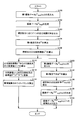
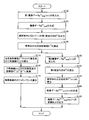
- FIG. 4 is a flowchart showing an overall processing procedure in image processing apparatus 1 according to the first embodiment of the present invention.
- the input unit 10 captures first imaging data g (1) RGB (m, n) obtained by imaging at least part of the light incident on the subject OBJ through the diffusing member 402. Is accepted (step S100). Subsequently, the input unit 10 generates imaging data g (1) RGB representing the received first imaging data g (1) RGB (m, n) (step S102). Note that the input unit 10 linearizes the first imaging data as necessary.
- the estimation matrix calculation unit 12 uses the autocorrelation matrix B of the spectral radiance of the light source candidates that can be used to provide the illumination environment in the subject OBJ, the spectral transmittance f (1) of the diffusing member 402, and the imaging device 400.
- the first estimation matrix W (1) is calculated based on the spectral sensitivity S (step S104).
- the spectral radiance calculation unit 11 uses the first estimation matrix W (1) calculated in step S104, and the spectral radiance E ( 1) of the illumination light incident on the subject OBJ from the imaging data g (1) RGB. 1) is calculated (step S106).
- the tristimulus value conversion unit 14 calculates tristimulus values X, Y, and Z of the XYZ color system from the spectral radiance E (1) (step S110). Subsequently, the coordinate conversion unit 15 converts the tristimulus values X, Y, and Z in the XYZ color system to coordinate values R (1) , G (1) , and B (1) defined in the RGB color system. (Step S112). Further, the white balance calculation unit 16 calculates the white balance in the imaging apparatus 400 based on the ratio of the coordinate values R (1) , G (1) , B (1) (step S114).
- the input unit 20 receives the second imaging data g (2) RGB (m, n) obtained by imaging the subject OBJ by the imaging device 400 in an illumination environment (step S120).
- the input unit 20 linearizes the second imaging data as necessary.
- the estimation matrix calculation unit 22 calculates the autocorrelation matrix A calculated from the spectral reflectances of colors that can be included in the subject OBJ, the spectral radiance E (1) of the illumination light calculated by the illumination spectrum estimation unit 100, Based on the spectral sensitivity S of the imaging device 400, a second estimation matrix W (2) is calculated (step S122). Subsequently, the spectral reflectance calculation unit 21 uses the second estimation matrix W (2) calculated in step S122 to calculate the spectral reflectance f (2) (m ) of the subject OBJ from the second imaging data g (2). , N) is calculated (step S124).
- the image data generation unit 24 uses the color matching function h, the spectral radiance E (1) of the illumination light incident on the subject OBJ, and the spectral reflectance f (2) (m ) of the subject OBJ calculated in step S124. , N) is used to generate image data g (OUT) XYZ (m, n) obtained by performing color reproduction of the subject OBJ (step S126). Further, the coordinate conversion unit 25 converts the image data g (OUT) XYZ (m, n) generated in step S126 into image data g (OUT) RGB (m, n) defined in the RGB color system. (Step S128), the converted image data g (OUT) RGB (m, n) is output.
- the spectral radiance of the illumination light applied to the subject OBJ can be calculated using the imaging device for imaging the subject OBJ. Therefore, the spectral radiance can be easily acquired without using a dedicated measuring device for measuring the spectral radiance of the illumination light.
- the spectral reflectance of the subject OBJ is accurately estimated, and then the color that will be imaged (observed) in the illumination environment to be imaged. Can be reproduced appropriately.
- the white balance of the imaging device can be adjusted appropriately based on the spectral radiance of the illumination light, more accurate color reproduction can be realized without being affected by variations in the characteristics of the imaging device.
- the second embodiment exemplifies a configuration in which a plurality of autocorrelation matrices are stored for each type of a plurality of light sources (for each category), and the user can select a suitable one for the illumination environment for imaging the subject OBJ.
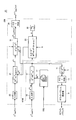
- FIG. 5 is a functional configuration diagram of an image processing apparatus 1A according to the second embodiment of the present invention.
- the image processing apparatus 1 ⁇ / b> A includes an illumination spectrum estimation unit 100 ⁇ / b> A in place of the illumination spectrum estimation unit 100 in the image processing apparatus 1 shown in FIG. 1.
- color reproduction unit 200 is similar to color reproduction unit 200 of image processing apparatus 1 shown in FIG. 1, and therefore detailed description thereof will not be repeated.
- the illumination spectrum estimation unit 100A is provided with a light source data storage unit 13A in place of the light source data storage unit 13 in the illumination spectrum estimation unit 100 shown in FIG. Since other parts are the same as those in the first embodiment, detailed description will not be repeated.
- the light source data storage unit 13A stores in advance an autocorrelation matrix B 1 , B 2 ,..., B M, which is a predetermined calculation matrix for each of M types of light source candidates that can be used to provide an illumination environment. Store. Then, the light source data storage unit 13A selects the selected one of the autocorrelation matrices B 1 , B 2 ,..., B M stored in advance in accordance with an external command from the user or the like. Output to.
- an autocorrelation matrix B 1 , B 2 ,..., B M which is a predetermined calculation matrix for each of M types of light source candidates that can be used to provide an illumination environment.
- the spectral irradiation luminance (spectrum) of a general fluorescent lamp has a waveform having a peak at a wavelength corresponding to an emission line spectrum of mercury or the like enclosed therein.
- the spectral illumination luminance (spectrum) of the incandescent lamp due to its emission principle.
- the spectral irradiation brightness (spectrum) of the light source candidate is different for each type. Therefore, in order to estimate the spectral radiance E (1) (illumination spectrum) of the illumination light incident on the subject OBJ, it is necessary to appropriately select the autocorrelation matrix B serving as a reference.
- a user having a certain level of prior knowledge can determine what light source is used in the illumination environment when the subject OBJ is imaged using the imaging device 400. For example, whether the subject OBJ is imaged indoors or outdoors, or if the imaged location is indoors, it is possible to determine whether a fluorescent light or an incandescent light is used as the light source. It is. Therefore, if a plurality of autocorrelation matrices are prepared in advance for each type of light source under such a classification that can be determined by the user and the user can arbitrarily select according to the imaging state of the subject OBJ, The estimation accuracy of the spectral radiance E (1) (illumination spectrum) can be increased.
- the light source data storage unit 13A includes a plurality of autocorrelation matrices for each type of “fluorescent lamp”, “incandescent lamp”, “xenon lamp”, “mercury lamp”, and “sunlight”.
- B 1 , B 2 ,..., B M are stored in advance, and in response to a selection command SEL by a user or the like, the corresponding one is output as an autocorrelation matrix B to the estimation matrix calculation unit 12. That is, the autocorrelation matrix B 1 is generated only from the statistical data of the spectral radiance of “fluorescent lamp”, and the autocorrelation matrix B 2 is generated only from the statistical data of the spectral radiance of “incandescent lamp”. is there.
- the estimation matrix calculation unit 12 estimates the spectral radiance E (1) of the illumination light based on the autocorrelation matrix B received from the light source data storage unit 13A.
- an autocorrelation matrix that further classifies the type of light source.
- an autocorrelation matrix may be generated based on the spectral radiance generated when, for example, a “fluorescent lamp” and an “incandescent lamp” are combined. That is, it is preferable to store in advance in the light source data storage unit 13A autocorrelation matrices generated based on various spectral radiances that are assumed as illumination environments when the subject OBJ is imaged.
- FIG. 6 is a flowchart showing an overall processing procedure in image processing apparatus 1A according to the second embodiment of the present invention. Of the steps in the flowchart shown in FIG. 6, steps having the same contents as the steps in the flowchart shown in FIG.
- the input unit 10 captures at least part of the light incident on the subject OBJ through the diffusion member 402. First imaging data g (1) RGB (m, n) Is accepted (step S100). Subsequently, the input unit 10 generates imaging data g (1) RGB representing the received first imaging data g (1) RGB (m, n) (step S102). Note that the input unit 10 linearizes the first imaging data as necessary.
- one autocorrelation matrix is estimated as an autocorrelation matrix B according to the selection command SEL. It outputs to the calculation part 12 (step S103). Thereafter, the estimation matrix calculator 12 determines the first estimation matrix W ( based on the autocorrelation matrix B from the light source data storage 13 ⁇ / b> A, the spectral transmittance f (1) of the diffusing member 402, and the spectral sensitivity S of the imaging device 400. 1) is calculated (step S104).
- the spectral radiance calculation unit 11 uses the first estimation matrix W (1) calculated in step S104, and the spectral radiance E ( 1) of the illumination light incident on the subject OBJ from the imaging data g (1) RGB. 1) is calculated (step S106).
- the tristimulus value conversion unit 14 calculates tristimulus values X, Y, and Z of the XYZ color system from the spectral radiance E (1) (step S110). Subsequently, the coordinate conversion unit 15 converts the tristimulus values X, Y, and Z in the XYZ color system to coordinate values R (1) , G (1) , and B (1) defined in the RGB color system. (Step S112). Further, the white balance calculation unit 16 calculates the white balance in the imaging apparatus 400 based on the ratio of the coordinate values R (1) , G (1) , B (1) (step S114).
- the input unit 20 receives the second imaging data g (2) RGB (m, n) obtained by imaging the subject OBJ by the imaging device 400 in an illumination environment (step S120).
- the input unit 20 linearizes the second imaging data as necessary.
- the estimation matrix calculation unit 22 calculates the autocorrelation matrix A calculated from the spectral reflectances of colors that can be included in the subject OBJ, the spectral radiance E (1) of the illumination light calculated by the illumination spectrum estimation unit 100, Based on the spectral sensitivity S of the imaging device 400, a second estimation matrix W (2) is calculated (step S122). Subsequently, the spectral reflectance calculation unit 21 uses the second estimation matrix W (2) calculated in step S122 to calculate the spectral reflectance f (2) (m ) of the subject OBJ from the second imaging data g (2). , N) is calculated (step S124).
- the image data generating unit 24 uses the color matching function h, the spectral radiance E (1) of the illumination light incident on the subject OBJ, and the spectral reflectance f (2) (m, ) of the subject OBJ calculated in step S124. n) is used to generate image data g (OUT) XYZ (m, n) in which color reproduction of the subject OBJ is performed (step S126). Further, the coordinate conversion unit 25 converts the image data g (OUT) XYZ (m, n) generated in step S126 into image data g (OUT) RGB (m, n) defined in the RGB color system. (Step S128), the converted image data g (OUT) RGB (m, n) is output.
- any one of a plurality of autocorrelation matrices is selected in response to a selection command SEL by a user or the like, and the first estimation matrix is further based on the selected autocorrelation matrix.
- the configuration in which W (1) is generated has been illustrated.
- the first estimation matrix W (1) is generated using the spectral transmittance f (1) of the diffusing member 402 and the spectral sensitivity S of the imaging device 400. These values are used for the imaging device 400 and the diffusing member 402. As long as is not exchanged.
- FIG. 7 is a functional configuration diagram of an image processing device 1B according to a modification of the second embodiment of the present invention.
- the image processing apparatus 1 ⁇ / b> B includes an illumination spectrum estimation unit 100 ⁇ / b> B instead of the illumination spectrum estimation unit 100 in the image processing apparatus 1 shown in FIG. 1.
- color reproduction unit 200 is the same as that of image processing apparatus 1 shown in FIG. 1, and therefore detailed description will not be repeated.
- the illumination spectrum estimation unit 100B includes an estimation matrix storage unit 17 instead of the estimation matrix calculation unit 12 and the light source data storage unit 13 in the illumination spectrum estimation unit 100 shown in FIG. Since other parts are the same as those in the first embodiment, detailed description will not be repeated.
- the estimation matrix storage unit 17 includes first estimation matrices W (1) 1 , W (1) 2 ,... That are calculated in advance based on spectral radiances of a plurality of light source candidates that can be used to provide an illumination environment. ., W (1) M is stored in advance. And the estimation matrix storage part 17 respond
- the first estimation matrix W (1) 1, W ( 1) 2, ⁇ , W (1) M is, B 1 is stored in the source data storage section 13A of the image processing apparatus 1A according to the second embodiment, Calculated from B 2 ,..., B M.
- FIG. 8 is a flowchart showing an overall processing procedure in image processing apparatus 1B according to the modification of the second embodiment of the present invention. Of the steps in the flowchart shown in FIG. 8, steps having the same contents as those in the flowchart shown in FIG. 4 are denoted by the same reference numerals.
- the input unit 10 captures first imaging data g (1) RGB (m, n) obtained by imaging at least a part of the light incident on the subject OBJ through the diffusing member 402. Is accepted (step S100). Subsequently, the input unit 10 generates imaging data g (1) RGB representing the received first imaging data g (1) RGB (m, n) (step S102). Note that the input unit 10 linearizes the first imaging data as necessary.
- the estimation matrix storage unit 17 selects one of the first estimation matrices W (1) 1 , W (1) 2 ,..., W (1) M stored in advance according to the selection command SEL.
- One estimation matrix is output to the spectral radiance calculation unit 11 as a first estimation matrix W (1) (step S105).
- the spectral radiance calculation unit 11 uses the first estimation matrix W (1) selected in step S105, and the spectral radiance E ( 1) of the illumination light incident on the subject OBJ from the imaging data g (1) RGB. 1) is calculated (step S106).
- the tristimulus value conversion unit 14 calculates tristimulus values X, Y, and Z of the XYZ color system from the spectral radiance E (1) (step S110). Subsequently, the coordinate conversion unit 15 converts the tristimulus values X, Y, and Z in the XYZ color system to coordinate values R (1) , G (1) , and B (1) defined in the RGB color system. (Step S112). Further, the white balance calculation unit 16 calculates the white balance in the imaging apparatus 400 based on the ratio of the coordinate values R (1) , G (1) , B (1) (step S114).
- the input unit 20 receives the second imaging data g (2) RGB (m, n) obtained by imaging the subject OBJ by the imaging device 400 in an illumination environment (step S120).
- the input unit 20 linearizes the second imaging data as necessary.
- the estimation matrix calculation unit 22 calculates the autocorrelation matrix A calculated from the spectral reflectances of colors that can be included in the subject OBJ, the spectral radiance E (1) of the illumination light calculated by the illumination spectrum estimation unit 100, Based on the spectral sensitivity S of the imaging device 400, a second estimation matrix W (2) is calculated (step S122). Subsequently, the spectral reflectance calculation unit 21 uses the second estimation matrix W (2) calculated in step S122 to calculate the spectral reflectance f (2) (m ) of the subject OBJ from the second imaging data g (2). , N) is calculated (step S124).
- the image data generating unit 24 uses the color matching function h, the spectral radiance E (1) of the illumination light incident on the subject OBJ, and the spectral reflectance f (2) (m, ) of the subject OBJ calculated in step S124. n) is used to generate image data g (OUT) XYZ (m, n) in which color reproduction of the subject OBJ is performed (step S126). Further, the coordinate conversion unit 25 converts the image data g (OUT) XYZ (m, n) generated in step S126 into image data g (OUT) RGB (m, n) defined in the RGB color system. (Step S128), the converted image data g (OUT) RGB (m, n) is output.
- Embodiment 3 In Embodiment 2 described above, a plurality of autocorrelation matrices are stored in advance for each type of light source data, and the spectral radiance (spectrum) of illumination light is estimated using an arbitrarily selected autocorrelation matrix. The configuration in which is performed is illustrated. On the other hand, in Embodiment 3 described below, the most appropriate estimation result is output after evaluating the estimation result of the spectral radiance of the illumination light using each of the plurality of autocorrelation matrices. The configuration will be exemplified.
- the image processing apparatus is the image processing apparatus 1 according to the first embodiment shown in FIG. 1 except that an illumination spectrum estimation unit 100C is provided instead of the illumination spectrum estimation unit 100.
- color reproduction unit 200 is the same as that of image processing apparatus 1 shown in FIG. 1, and therefore detailed description will not be repeated.
- FIG. 9 is a functional configuration diagram of illumination spectrum estimation unit 100C of the image processing device according to the third embodiment of the present invention.
- the color reproduction unit 200 included in the image processing apparatus according to the present embodiment is not shown.
- the illumination spectrum estimation unit 100C includes an input unit 10, spectral radiance calculation units 11A, 11B, 11C, and 11D, a selection unit 18, an evaluation unit 19, and a tristimulus value conversion unit 14.
- the coordinate conversion unit 15 and the white balance calculation unit 16 are further included.
- the input unit 10, the tristimulus value conversion unit 14, the coordinate conversion unit 15, and the white balance calculation unit 16 have been described in the first embodiment (FIG. 1), detailed description will be repeated. Absent.
- Spectral radiance calculation units 11A, 11B, 11C, and 11D calculate first estimation matrices W (1) 1 , W ( based on spectral radiances of a plurality of light source candidates that can be used to provide an illumination environment. 1) Spectral radiance E (1) 1 , E (1) 2 , E of illumination light incident on subject OBJ from imaging data g (1) using 2 , W (1) 3 , W (1) 4 (1) 3 and E (1) Calculate 4 respectively.
- the first estimation matrix W (1) 1 , W (1) 2 , W (1) 3 , W (1) 4 is the first estimation matrix W (1) stored in the estimation matrix storage unit 17 shown in FIG. 1 , W (1) 2 , W (1) 3 , and W (1) 4 are substantially the same.
- the first estimation matrix W (1) 1 , W (1) 2 , W (1) 3 , W (1) 4 is previously stored for each type of a plurality of light source candidates that can be used to provide an illumination environment. Based on the determined autocorrelation matrices B 1 , B 2 , B 3 , B 4 , the calculation is performed according to the same procedure as described above.
- the number is not restrict
- FIG. 9 illustrates a configuration in which the first estimation matrix W (1) 1 , W (1) 2 , W (1) 3 , W (1) 4 is calculated in advance. Like the illumination spectrum estimation unit 100A, these may be dynamically calculated for each calculation process.
- the first estimation matrix W (1) 1 is calculated from the autocorrelation matrix B 1 created based on the fluorescent lamp statistical data
- the first estimation matrix W (1) 2 is calculated from the autocorrelation matrix B 2 created based on the incandescent lamp statistical data
- the first estimation matrix W (1) 3 is the autocorrelation matrix created based on the xenon lamp statistical data. It assumed to be calculated from the B 3.
- the first estimation matrix W (1) 4 is calculated from an autocorrelation matrix B 4 created based on statistical data including all of the fluorescent lamp, the incandescent lamp, and the xenon lamp.
- Spectral radiance calculation units 11A, 11B, 11C, and 11D select the calculated spectral radiances E (1) 1 , E (1) 2 , E (1) 3 , and E (1) 4 of the illumination light, respectively. 18 respectively.
- the selection unit 18 selects one of the spectral radiances E (1) 1 , E (1) 2 , E (1) 3 , and E (1) 4 of the input illumination light according to the evaluation result by the evaluation unit 19 described later. Are output as the spectral radiance E (1) of the illumination light.
- the evaluation unit 19 includes spectral radiances E (1) 1 , E (1) 2 , E (1) 3 , E (1) 4 of the illumination light calculated by the spectral radiance calculation units 11A, 11B, 11C, and 11D, respectively. Of these, the one that is most appropriately estimated is evaluated. More specifically, the evaluation unit 19 compares the spectral radiance E (1) 1 , E (1) 2 , E (1) 3 , E (1) of the illumination light by comparing with a reference pattern defined in advance. 4 is evaluated.
- first estimation matrices W (1) 1 , W (1) 2 , W (1) 3 (or corresponding autocorrelation matrices B 1 , B 2 , B 3 ), respectively.
- the reference patterns E (1) 1AVE , E (1) 2AVE , E (1) 3AVE calculated from the spectral radiance (statistical value or actually measured value) of the light source used at times are used. More specifically, for example, a reference pattern E (1) 1AVE corresponding to the first estimation matrix W (1) 1, the generation of the autocorrelation matrix B 1 used in the calculation of the first estimated matrix W (1) 1 It is calculated by averaging each element of the original light source group matrix E st (see FIG. 3). That is, as shown in FIG.
- spectral radiance (spectrum) representative of each of a fluorescent lamp, an incandescent lamp, and a xenon lamp is calculated in advance as a reference pattern.
- the reference pattern corresponding to the first estimation matrix W (1) 4 is not necessarily calculated. This is because the autocorrelation matrix B 4 corresponding to the first estimation matrix W (1) 4 is created based on statistical data including all of the fluorescent lamp, the incandescent lamp, and the xenon lamp. even create a reference pattern from the B 4, will blurred characteristics of each light source, because the effect of the reference pattern Usumaru.
- the evaluation unit 19 evaluates the spectral radiance E (1) 1 , E (1) 2 , E (1) 3 , E (1) 4 of the illumination light. explain.
- FIG. 10 shows the spectral radiance E (1) 1 , E (1) 2 , E (1) 3 and the reference pattern E (1) 1AVE , E (1) 2AVE , E (1) of the illumination light by the evaluation unit 19. It is a figure for demonstrating the comparison process with 3AVE .
- FIG. 11 is a diagram for explaining the similarity calculation process in FIG. 10.
- the evaluation unit 19 includes spectral radiances E (1) 1 , E (1) 2 , E (1) 3 of illumination light calculated by the spectral radiance calculation units 11A, 11B, and 11C, respectively.
- the reference patterns E (1) 1AVE , E (1) 2AVE , E (1) 3AVE are respectively compared, and the comparison result (similarity as an example) is calculated.
- the spectral radiance E (1) 1 , E (1) 2 , E (1) 3 and the reference pattern E (1) 1AVE , E (1) 2AVE , E (1) 3AVE are all 0. It is assumed that it is standardized in the range of ⁇ 1.
- the evaluation unit 19 evaluates how similar each spectral radiance is to the corresponding reference pattern. Typically, the evaluation unit 19 calculates the similarity based on the deviation between the waveforms on the wavelength region.
- FIG. 11 is a diagram for explaining a comparison process between the spectral radiance E (1) 1 of the illumination light calculated by the spectral radiance calculation unit 11A and the reference pattern E (1) 1AVE .
- FIG. 11A shows a state where the spectral radiance E (1) 1 of the illumination light and the reference pattern E (1) 1AVE are plotted on the same wavelength region, and FIG. The process which calculates a deviation is shown.
- the evaluation unit 19 calculates the deviation (standardized value) err j between the spectral radiance E (1) 1 of the illumination light and the reference pattern E (1) 1AVE at each sampling wavelength ⁇ j (1 ⁇ j ⁇ k). (1 ⁇ j ⁇ k) is calculated sequentially. Subsequently, the evaluation unit 19 calculates an evaluation result (similarity) by calculating a total average of all the deviations err j of the sampling wavelength ⁇ j . That is, the similarity SM can be calculated by the following arithmetic expression using the deviation err j of the sampling wavelength ⁇ j .
- FIG. 10 shows the measured similarity when the image processing method according to the present embodiment is performed under the illumination environment of a fluorescent lamp.
- the similarity of the spectral radiance E (1) 1 of the illumination light estimated based on the first estimation matrix W (1) 1 is the highest.
- the spectral radiance E (1) 1 of the illumination light is output as the spectral radiance E (1) .
- this evaluation result agrees with the fact that it was actually measured under the fluorescent lamp illumination environment.
- the spectral radiance E (1) of the illumination light is provided by combining a fluorescent lamp, an incandescent lamp, and a xenon lamp, or provided by a light source other than these.
- the spectral radiance E (1) 4 of the illumination light estimated based on the first estimation matrix W (1) 4 reflecting all the characteristics of the fluorescent lamp, the incandescent lamp, and the xenon lamp is used as the illumination light. It may be appropriate to output as the spectral radiance E (1) .
- the evaluation unit 19 is used when the evaluation results (similarities) for the spectral radiances E (1) 1 , E (1) 2 , E (1) 3 of the illumination light are all below the allowable value. outputs the spectral radiance E (1) 4 as the spectral radiance E of the illumination light (1).
- the spectral radiance calculation units 11A, 11B, 11C, and 11D perform spectral radiance E (1) 1 , E (1) 2 , E (1) 3 , E (1) 4 of illumination light.
- the calculation process of the spectral radiance of the illumination light and the calculation process of the similarity degree are sequentially executed for each of the first estimation matrices. May be.
- a predetermined threshold for example, 95%)
- the similarity may be calculated using a correlation coefficient or the like.
- FIG. 12 is a flowchart showing an overall processing procedure in the image processing apparatus according to the third embodiment of the present invention. Of the steps in the flowchart shown in FIG. 12, steps having the same contents as those in the flowchart shown in FIG. 4 are denoted by the same reference numerals.
- FIG. 13 is a flowchart showing the procedure of the evaluation subroutine shown in step S108 shown in FIG.
- the input unit 10 captures at least part of the light incident on the object OBJ through the diffusion member 402. First imaging data g (1) RGB (m, n) Is accepted (step S100). Subsequently, the input unit 10 generates imaging data g (1) RGB representing the received first imaging data g (1) RGB (m, n) (step S102). Note that the input unit 10 linearizes the first imaging data as necessary.
- the spectral radiance calculation units 11A, 11B, 11C, and 11D capture images using the first estimation matrices W (1) 1 , W (1) 2 , W (1) 3 , and W (1) 4 , respectively.
- Data g (1) Spectral radiance E (1) 1 , E (1) 2 , E (1) 3 , E (1) 4 of the illumination light incident on the subject OBJ from RGB is calculated (step S107).
- the evaluation unit 19 executes an evaluation subroutine, and the spectral radiances E (1) 1 , E (1) 2 , E (1) 3 , and E (1) 4 of the illumination light calculated in step S107. Among them, the one with the highest estimation accuracy is evaluated (step S108). Further, the selection unit 18, according to the evaluation result in step S108, one of the spectral radiance E of the illumination light (1) 1, E (1 ) 2, E (1) 3, E (1) 4, lighting Output as spectral radiance E (1) of light (step S109).
- the tristimulus value conversion unit 14 calculates tristimulus values X, Y, and Z of the XYZ color system from the spectral radiance E (1) (step S110). Subsequently, the coordinate conversion unit 15 converts the tristimulus values X, Y, and Z in the XYZ color system to coordinate values R (1) , G (1) , and B (1) defined in the RGB color system. (Step S112). Further, the white balance calculation unit 16 calculates the white balance in the imaging apparatus 400 based on the ratio of the coordinate values R (1) , G (1) , B (1) (step S114).
- the input unit 20 receives the second imaging data g (2) RGB (m, n) obtained by imaging the subject OBJ by the imaging device 400 in an illumination environment (step S120).
- the input unit 20 linearizes the second imaging data as necessary.
- the estimation matrix calculation unit 22 calculates the autocorrelation matrix A calculated from the spectral reflectances of colors that can be included in the subject OBJ, the spectral radiance E (1) of the illumination light calculated by the illumination spectrum estimation unit 100, Based on the spectral sensitivity S of the imaging device 400, a second estimation matrix W (2) is calculated (step S122). Subsequently, the spectral reflectance calculation unit 21 uses the second estimation matrix W (2) calculated in step S122 to calculate the spectral reflectance f (2) (m ) of the subject OBJ from the second imaging data g (2). , N) is calculated (step S124).
- the image data generating unit 24 uses the color matching function h, the spectral radiance E (1) of the illumination light incident on the subject OBJ, and the spectral reflectance f (2) (m, ) of the subject OBJ calculated in step S124. n) is used to generate image data g (OUT) XYZ (m, n) in which color reproduction of the subject OBJ is performed (step S126). Further, the coordinate conversion unit 25 converts the image data g (OUT) XYZ (m, n) generated in step S126 into image data g (OUT) RGB (m, n) defined in the RGB color system. (Step S128), the converted image data g (OUT) RGB (m, n) is output.
- the evaluation unit 19 compares the spectral radiance E (1) 1 of the illumination light with a predetermined reference pattern E (1) 1AVE , thereby determining the similarity SM 1 between the two. Is calculated (step S200). Similarly, the evaluation unit 19 compares the spectral radiance E (1) 2 of the illumination light with a predetermined reference pattern E (1) 2AVE to calculate the similarity SM 2 between them ( Step S202). Similarly, the evaluation unit 19 compares the spectral radiance E (1) 3 of the illumination light with a predetermined reference pattern E (1) 3AVE to calculate a similarity SM 3 between them ( Step S204).
- the evaluation unit 19 extracts the one having the highest value among the similarities SM 1 , SM 2 , SM 3 calculated in steps S200, S202, S204 (step S206). Furthermore, the evaluation unit 19 determines whether or not the similarity extracted in step S206 is greater than or equal to a predetermined allowable value (step S208).
- the evaluation unit 19 evaluates that the spectral radiance corresponding to the similarity extracted in step S206 has the highest estimation accuracy (Ste S210).
- the evaluation unit 19 evaluates the spectral radiance E (1) 1 , E (1) 2 , E (1) of the illumination light. It is evaluated that the spectral radiance E (1) 4 of illumination light other than 3 has the highest estimation accuracy (step S212).
- the processing proceeds to step S109 in FIG. ⁇ Operational effects of the present embodiment>
- the same operational effects as those of the above-described first embodiment can be obtained, and the spectral radiance of illumination light is high even for a user who does not have any prior knowledge. It can be obtained with estimation accuracy. Therefore, even if the subject OBJ is performed under various conditions, the estimation accuracy of the spectral radiance of the illumination light can be maintained.
- FIG. 14 is a schematic configuration diagram of a computer that realizes an image processing apparatus 1 # according to a modification of the embodiment of the present invention.
- the computer includes a computer main body 150 equipped with an FD (Flexible Disk) driving device 166 and a CD-ROM (Compact Disk-Read Only Memory) driving device 168, a monitor 152, a keyboard 154, a mouse. 156.
- FD Flexible Disk
- CD-ROM Compact Disk-Read Only Memory
- the computer main body 150 further includes a CPU (Central Processing Unit) 160 that is an arithmetic device, a memory 162, a fixed disk 164 that is a storage device, and a communication interface 170 that are connected to each other via a bus.
- a CPU Central Processing Unit
- Image processing apparatus 1 # can be realized by CPU 160 executing software using computer hardware such as memory 162.
- such software is stored in a recording medium such as the FD 166a or the CD-ROM 168a, or distributed via a network or the like.
- Such software is read from the recording medium by the FD driving device 166 or the CD-ROM driving device 168 or received by the communication interface 170 and stored in the fixed disk 164. Further, it is read from the fixed disk 164 to the memory 162 and executed by the CPU 160.
- the monitor 152 is a display unit for displaying information output by the CPU 160, and includes, for example, an LCD (Liquid Crystal Display), a CRT (Cathode Ray Tube), and the like.
- the mouse 156 receives a command from a user corresponding to an operation such as click or slide.
- the keyboard 154 receives a command from the user corresponding to the input key.
- the CPU 160 is an arithmetic processing unit that executes various arithmetic operations by sequentially executing programmed instructions.
- the memory 162 stores various types of information according to the program execution of the CPU 160.
- the communication interface 170 converts the information output from the CPU 160 into, for example, an electrical signal and sends it to another device, and receives the electrical signal from the other device and converts it into information that can be used by the CPU 160.
- Fixed disk 164 is a non-volatile storage device that stores programs executed by CPU 160 and predetermined data. In addition, other output devices such as a printer may be connected to the computer as necessary.
- the program according to the present embodiment is a program module that is provided as a part of a computer operating system (OS) and calls necessary modules in a predetermined arrangement at a predetermined timing to execute processing. There may be. In that case, the program itself does not include the module, and the process is executed in cooperation with the OS. A program that does not include such a module can also be included in the program according to the present invention.
- OS computer operating system
- the program according to the present embodiment may be provided by being incorporated in a part of another program. Even in this case, the program itself does not include the module included in the other program, and the process is executed in cooperation with the other program.
Landscapes
- Physics & Mathematics (AREA)
- General Physics & Mathematics (AREA)
- Spectroscopy & Molecular Physics (AREA)
- Engineering & Computer Science (AREA)
- Multimedia (AREA)
- Signal Processing (AREA)
- Color Image Communication Systems (AREA)
- Color Television Image Signal Generators (AREA)
- Spectrometry And Color Measurement (AREA)
Abstract
Une unité de calcul de matrice d'estimation (12) calcule une première matrice d'estimation (W(1)), sur la base de la matrice d'autocorrélation de la luminance énergétique spectrale d'une source de lumière candidate pouvant être utilisée pour fournir un environnement d'éclairage dans un objet, d'un facteur de transmission spectrale (f(1)) d'un élément de dispersion et de la sensibilité spectrale (S) d'un dispositif de capture d'image. Une unité de calcul de luminance énergétique spectrale (11) calcule la luminance énergétique spectrale (E(1)) d'une lumière d'éclairage qui est incidente sur un objet (OBJ), à partir de données de capture d'image (g(1) RGB), en utilisant la première matrice d'estimation (W(1)) calculée par l'unité de calcul de matrice d'estimation (12).
Applications Claiming Priority (4)
| Application Number | Priority Date | Filing Date | Title |
|---|---|---|---|
| JP2008021395A JP5120936B2 (ja) | 2008-01-31 | 2008-01-31 | 画像処理装置および画像処理方法 |
| JP2008-021395 | 2008-01-31 | ||
| JP2008021394A JP2009182845A (ja) | 2008-01-31 | 2008-01-31 | 画像処理装置および画像処理方法 |
| JP2008-021394 | 2008-08-21 |
Publications (1)
| Publication Number | Publication Date |
|---|---|
| WO2009096232A1 true WO2009096232A1 (fr) | 2009-08-06 |
Family
ID=40912585
Family Applications (1)
| Application Number | Title | Priority Date | Filing Date |
|---|---|---|---|
| PCT/JP2009/050453 Ceased WO2009096232A1 (fr) | 2008-01-31 | 2009-01-15 | Dispositif et procédé de traitement d'image |
Country Status (1)
| Country | Link |
|---|---|
| WO (1) | WO2009096232A1 (fr) |
Citations (2)
| Publication number | Priority date | Publication date | Assignee | Title |
|---|---|---|---|---|
| JP2002344979A (ja) * | 2001-05-21 | 2002-11-29 | Minolta Co Ltd | デジタル撮像装置、照明成分取得方法、プログラム及び記録媒体 |
| JP2005202673A (ja) * | 2004-01-15 | 2005-07-28 | Kddi Corp | 画像認識装置 |
-
2009
- 2009-01-15 WO PCT/JP2009/050453 patent/WO2009096232A1/fr not_active Ceased
Patent Citations (2)
| Publication number | Priority date | Publication date | Assignee | Title |
|---|---|---|---|---|
| JP2002344979A (ja) * | 2001-05-21 | 2002-11-29 | Minolta Co Ltd | デジタル撮像装置、照明成分取得方法、プログラム及び記録媒体 |
| JP2005202673A (ja) * | 2004-01-15 | 2005-07-28 | Kddi Corp | 画像認識装置 |
Non-Patent Citations (3)
| Title |
|---|
| PLATT W.K. ET AL.: "Spectral estimation techniques for the spectral calibration of a color image scanner", APPLIED OPTICS, vol. 15, no. 1, January 1976 (1976-01-01), pages 73 - 75 * |
| TOMINAGA M.: "A Technique for Multi-band Imaging and Its Application to Vision", TRANSACTIONS OF INFORMATION PROCESSING SOCIETY OF JAPAN (CVIM13, vol. 47, no. SIG5, 15 March 2006 (2006-03-15), pages 20 - 34 * |
| UCHIYAMA T. ET AL.: "Capture of natural illumination environments and spectral-based image synthesis", IEICE TECHNICAL REPORT, vol. 105, no. 535, 12 January 2006 (2006-01-12), pages 7 - 12 * |
Similar Documents
| Publication | Publication Date | Title |
|---|---|---|
| KR100278642B1 (ko) | 칼라 영상 처리장치 및 방법 | |
| US7436997B2 (en) | Light source estimating device, light source estimating method, and imaging device and image processing method | |
| US10168215B2 (en) | Color measurement apparatus and color information processing apparatus | |
| US20190079004A1 (en) | Systems and methods for optical spectrometer calibration | |
| US6538242B1 (en) | Method of measuring spectral responsivity characteristic of image pick-up device and method of configuring imaging data | |
| US20070236715A1 (en) | Image pickup apparatus and its light source estimating apparatus | |
| JP7687559B2 (ja) | 撮像システム | |
| JP6969164B2 (ja) | 評価装置、評価プログラム及び評価方法 | |
| US7457000B2 (en) | Image input system, conversion matrix calculating method, and computer software product | |
| US11825211B2 (en) | Method of color inspection by using monochrome imaging with multiple wavelengths of light | |
| JP5841091B2 (ja) | 画像色分布検査装置および画像色分布検査方法 | |
| US7616314B2 (en) | Methods and apparatuses for determining a color calibration for different spectral light inputs in an imaging apparatus measurement | |
| JP5120936B2 (ja) | 画像処理装置および画像処理方法 | |
| JP2009182845A (ja) | 画像処理装置および画像処理方法 | |
| JP4174707B2 (ja) | 分光測定システム、色再現システム | |
| JP2009188807A (ja) | 撮像方法および撮像システム | |
| JP2006090897A (ja) | 2種類の光源を用いた分光反射率推定方式 | |
| WO2009096232A1 (fr) | Dispositif et procédé de traitement d'image | |
| JPH11304589A (ja) | 環境光測定システム | |
| JP6813749B1 (ja) | 対象物の色を数値化する方法、信号処理装置、および撮像システム | |
| JP3577977B2 (ja) | 照明光分光特性推定装置 | |
| JP4588076B2 (ja) | 撮像方法および撮像システム | |
| JP5895094B1 (ja) | 画像色分布検査装置および画像色分布検査方法 | |
| WO2009098968A1 (fr) | Procédé d'imagerie et système d'imagerie | |
| JP2008534951A (ja) | イルミナントの推定 |
Legal Events
| Date | Code | Title | Description |
|---|---|---|---|
| 121 | Ep: the epo has been informed by wipo that ep was designated in this application |
Ref document number: 09706560 Country of ref document: EP Kind code of ref document: A1 |
|
| DPE2 | Request for preliminary examination filed before expiration of 19th month from priority date (pct application filed from 20040101) | ||
| NENP | Non-entry into the national phase |
Ref country code: DE |
|
| 122 | Ep: pct application non-entry in european phase |
Ref document number: 09706560 Country of ref document: EP Kind code of ref document: A1 |