WO2009096360A1 - Débitmètre électromagnétique - Google Patents
Débitmètre électromagnétique Download PDFInfo
- Publication number
- WO2009096360A1 WO2009096360A1 PCT/JP2009/051193 JP2009051193W WO2009096360A1 WO 2009096360 A1 WO2009096360 A1 WO 2009096360A1 JP 2009051193 W JP2009051193 W JP 2009051193W WO 2009096360 A1 WO2009096360 A1 WO 2009096360A1
- Authority
- WO
- WIPO (PCT)
- Prior art keywords
- pipe
- cylindrical portion
- lining
- measurement
- inner peripheral
- Prior art date
- Legal status (The legal status is an assumption and is not a legal conclusion. Google has not performed a legal analysis and makes no representation as to the accuracy of the status listed.)
- Ceased
Links
Images
Classifications
-
- G—PHYSICS
- G01—MEASURING; TESTING
- G01F—MEASURING VOLUME, VOLUME FLOW, MASS FLOW OR LIQUID LEVEL; METERING BY VOLUME
- G01F1/00—Measuring the volume flow or mass flow of fluid or fluent solid material wherein the fluid passes through a meter in a continuous flow
- G01F1/56—Measuring the volume flow or mass flow of fluid or fluent solid material wherein the fluid passes through a meter in a continuous flow by using electric or magnetic effects
- G01F1/58—Measuring the volume flow or mass flow of fluid or fluent solid material wherein the fluid passes through a meter in a continuous flow by using electric or magnetic effects by electromagnetic flowmeters
-
- G—PHYSICS
- G01—MEASURING; TESTING
- G01F—MEASURING VOLUME, VOLUME FLOW, MASS FLOW OR LIQUID LEVEL; METERING BY VOLUME
- G01F15/00—Details of, or accessories for, apparatus of groups G01F1/00 - G01F13/00 insofar as such details or appliances are not adapted to particular types of such apparatus
- G01F15/006—Details of, or accessories for, apparatus of groups G01F1/00 - G01F13/00 insofar as such details or appliances are not adapted to particular types of such apparatus characterised by the use of a particular material, e.g. anti-corrosive material
Definitions
- the present invention relates to an electromagnetic flow meter used to measure the flow rate of a conductive fluid.
- a flange type having a measurement pipe made of a straight pipe and having a flange for pipe connection integrally at both ends thereof
- a wafer type not having a flange.
- the flange type electromagnetic flowmeter coats the lining material on the inner peripheral surface of the measurement pipe and the surface of the flange (pipe connection end face)
- the wafer type electromagnetic flowmeter also applies the inner peripheral surface and end face of the measurement pipe By coating a lining material on the pipe connection end face), the measuring pipe and the fluid to be measured flowing in the measuring pipe are electrically isolated from each other.
- a pair of excitation coils are disposed on the outer peripheral surface of the measurement pipe so as to face each other with the measurement pipe interposed therebetween, and a pair of electrodes whose axis is orthogonal to the magnetic field by the excitation coil are tube walls of the measurement pipe The earth ring is attached to the end of the pipe connection.
- the earth ring grounds the fluid to be measured flowing in the measuring pipe and the measuring tube to the same potential and detects the reference potential of the measurement, thereby generating noise caused by the instability of the potential of the fluid to be measured. It has a function to erase and a function to protect the lining material coated on the pipe connection end face.
- Such an earth ring is usually made of stainless steel 316 or the like, but is formed of a noble metal such as platinum, titanium, monel, hastelloy or the like when corrosion resistance and wear resistance are required.
- the platinum paste is formed by baking. There is also something to do.
- the present invention has been made to solve the above-mentioned conventional problems, and the object of the present invention is to reliably protect the lining portion which is easily scraped by solids mixed in the liquid, and to measure it.
- An object of the present invention is to provide an electromagnetic flowmeter which has a small error and improves reliability and durability.
- the electromagnetic flow meter comprises: a measuring pipe; a lining material coated on an inner circumferential surface of the measuring pipe and a pipe connection end; an exciting coil disposed on an outer peripheral surface of the measuring pipe; An earth ring disposed on the end face via the lining material is provided, and the earth ring has a cylindrical portion covering the lining material in the vicinity of the opening on the inner peripheral surface of the measurement pipe.
- the lining material in the vicinity of the opening on the inner circumferential surface of the measuring pipe is covered by the cylindrical portion provided on the earth ring, the solid material in which the lining material near the opening on the inner circumferential surface is mixed in the liquid Can be prevented from being scraped off and measurement errors can be reduced. Since the area around the inner circumferential surface opening of the measuring pipe is the place where the lining material is most easily scraped off by the solid substance, it is extremely effective to protect the lining material near this inner circumferential surface opening with a cylindrical portion.
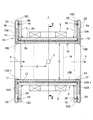
- FIG. 1 is a cross-sectional view showing an embodiment of an electromagnetic flowmeter according to the present invention.
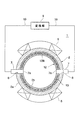
- FIG. 2 is a cross-sectional view taken along line II-II of FIG.
- FIGS. 1 and 2 show an example where the present embodiment is applied to an electromagnetic flowmeter 1 provided with a flange type measurement pipe 2.
- the measurement pipe 2 is a straight pipe open at both ends formed of a nonmagnetic material such as SUS, and flanges 3 are joined to both ends of the outer peripheral surface 2 a by TIG welding or the like.
- the flange 3 is formed of the same material or a different material as the measurement pipe 2, and the surface 3 a forms a connection end face (a pipe connection end face) to which the pipe is connected.
- a pair of exciting coils 5 for generating a magnetic field H in a direction perpendicular to the flow direction of the fluid to be measured 4 flowing in the measuring pipe 2 is vertically generated at the axial center of the outer peripheral surface 2a of the measuring pipe 2 Are provided to face each other. These exciting coils 5 are connected to a power supply.
- a pair of electrodes 7 whose axes are orthogonal to both the magnetic field H of the excitation coil 5 and the flow direction of the fluid to be measured 4 are attached at the axial center of the measuring tube 2 so that they face each other. It is done. These electrodes 7 are inserted through the through holes 8 formed in the tube wall of the measurement tube 2 and the inner end is exposed in the measurement tube 2 to form a liquid contact surface 7 a with the fluid 4 to be measured, The outer end is connected to the conversion unit 9 provided at the top of the measurement pipe 2 via the signal line 10.
- a lining material 12 is coated on the inner peripheral surface 2b of the measurement pipe 2 and the pipe connection end 3a of each flange 3 in order to prevent a short circuit between the measurement pipe 2 and the electromotive force generated in the fluid 4 to be measured.
- a reinforcing pipe 13 is embedded therein.
- an electrically insulating material such as a fluorine resin excellent in heat resistance, corrosion resistance, and insulation is used, and is formed by injection molding or rotational molding.
- the reinforcing pipe 13 enhances the mechanical bond strength between the measuring pipe 2 and the lining material 12 and prevents the lining material 12 from peeling off from the measuring pipe 2, and lining by the temperature change or pressure change of the fluid 4 to be measured. It is buried in order to prevent the deformation and the like of the material 12.
- the reinforcing tube 13 is formed in a tubular shape by a perforated plate usually called a punching plate, and is fixed to the inner circumferential surface 2 b of the measuring tube 2 via a ring-shaped spacer 14.
- earth rings 15 formed of SUS, platinum, titanium, monel, hastelloy or the like are fixed to the pipe connection end face 3a of each flange 3 of the measurement pipe 2 by a plurality of set screws 16, respectively.
- the earth ring 15 has a disk-like ring main body 15A having a central hole 17, a cylindrical portion 15B integrally protruded from an inner peripheral edge of the ring main body 15A, and a circumferential direction at an outer peripheral edge of the ring main body 15A.
- a plurality of, for example, four fixing portions 15C which are formed in a J shape on the back side at intervals are formed.
- the ring body 15A has an outer diameter substantially equal to that of the flange 3 and is in close contact with the lining portion 12A coated on the pipe connection end face 3a of the flange 3.
- the reinforcing pipe 13 and the spacer 14 may be integrally formed.
- the cylindrical portion 15B is coated on the inner circumferential surface 2b by being protruded on the back surface side from the inner peripheral edge on the back surface side of the ring main body 15A, that is, the peripheral edge of the center hole 17 and inserted into the inside from the opening of the measuring tube 2.
- Solid substances in close contact with the surface of the lining portion 12B-1 covering the vicinity of the opening of the inner circumferential surface 2b of the measuring pipe 2, that is, the solids mixed in the fluid 4 to be measured I am protected.
- the lining portion 12B covering particularly the vicinity of the opening of the measuring pipe 2 is the portion most likely to be scraped off by the solid matter in the fluid 4 to be measured. Because of this, it is extremely effective to cover and protect this portion by the cylindrical portion 15B.
- the cylindrical portion 15B it is desirable to cover the lining portion 12B-1 in the vicinity of the opening on the inner peripheral surface of the measuring tube 2 within the range not affecting the magnetic field H by the exciting coil 5. Specifically, when the length of the cylindrical portion 15B is about several mm to several tens of mm and the inner diameter of the lining portion 12B coated on the inner circumferential surface 2b is D, from the tip of the cylindrical portion 15B to the electrode 7 It is desirable that the length E be approximately 0.65 D.
- the cylindrical portion 15B is formed such that the wall thickness gradually decreases toward the distal end on the proximal end side, that is, on the ring main body 15A side at the maximum. Therefore, the tip of the cylindrical portion 15B forms a knife edge. Further, the inner surface of the cylindrical portion 15B is formed with a tapered hole whose diameter increases toward the tip.
- the fixing portion 15 ⁇ / b> C is fixed to the outer periphery of the pipe connection end surface 3 a of the flange 3 by the set screw 16. For this reason, in the fixing portion 15C, a screw mounting hole 22 through which the set screw 16 is inserted is formed. Further, a screw hole 23 through which the set screw 16 is inserted is formed at a position corresponding to the screw mounting hole 22 of the fixed portion 15C near the outer periphery of the ring main body 15A.
- the ring main body 15A covers the lining portion 12B and the cylindrical portion 15B is the lining portion 12B-1 which is the end of the lining portion 12B. Cover and equalize the potentials of the measurement pipe 2 and the fluid to be measured 4 flowing in the measurement pipe 2.
- the earth ring 15 is electrically connected to the arithmetic processing circuit in the conversion unit 9 to lead the potential of the fluid 4 to be measured as a reference potential.
- the lining portion 12B covering the inner circumferential surface 2b of the measuring tube 2 by the cylindrical portion 15B integrally projecting on the inner peripheral edge of the earth ring 15, particularly the measuring tube 2 Since the lining portion 12B-1 covering the vicinity of the opening is protected, there is no possibility that the lining portion 12B-1 is scraped off by the solid matter mixed in the fluid 4 to be measured. Durability can be improved. In addition, if the lining portion 12B-1 is not scraped off by a solid, the measurement error is small, and the measurement accuracy can be improved.
- the vicinity of the inner peripheral surface opening of the measuring tube 2 is limited within a range in which the cylindrical portion 15B of the earth ring 15 does not affect the magnetic field H by the excitation coil 5 Since the lining portion 12B-1 of the second embodiment is covered, the measurement can be well performed without affecting the measurement.
- the tip is formed in an edge shape by gradually reducing the thickness of the cylindrical portion 15B from the base end toward the tip, It can prevent the occurrence. That is, when the cylindrical portion 15B having a constant thickness is inserted into the measurement pipe 2 to cover the lining portion 12B-1, the thickness of the cylindrical portion 15B becomes a step with respect to the lining portion 12B-1, It disturbs the flow of the fluid to be measured 4 and adversely affects the measurement. On the other hand, when the thickness of the cylindrical portion 15B is gradually reduced from the proximal end toward the distal end to form the tip in an edge shape, a step is generated between the lining portion 12B-1 and the cylindrical portion 15B. Because there is no risk of disturbing the flow of the fluid 4 to be measured, it does not affect the measurement.
Landscapes
- Physics & Mathematics (AREA)
- Fluid Mechanics (AREA)
- General Physics & Mathematics (AREA)
- Electromagnetism (AREA)
- Measuring Volume Flow (AREA)
Abstract
Applications Claiming Priority (2)
| Application Number | Priority Date | Filing Date | Title |
|---|---|---|---|
| JP2008-016272 | 2008-01-28 | ||
| JP2008016272A JP5271552B2 (ja) | 2008-01-28 | 2008-01-28 | 電磁流量計 |
Publications (1)
| Publication Number | Publication Date |
|---|---|
| WO2009096360A1 true WO2009096360A1 (fr) | 2009-08-06 |
Family
ID=40912713
Family Applications (1)
| Application Number | Title | Priority Date | Filing Date |
|---|---|---|---|
| PCT/JP2009/051193 Ceased WO2009096360A1 (fr) | 2008-01-28 | 2009-01-26 | Débitmètre électromagnétique |
Country Status (2)
| Country | Link |
|---|---|
| JP (1) | JP5271552B2 (fr) |
| WO (1) | WO2009096360A1 (fr) |
Cited By (2)
| Publication number | Priority date | Publication date | Assignee | Title |
|---|---|---|---|---|
| CN113155221A (zh) * | 2021-04-16 | 2021-07-23 | 浙江大学 | 一种液态金属流量计及铅铋冷却系统 |
| CN115698645A (zh) * | 2020-06-19 | 2023-02-03 | 恩德斯+豪斯流量技术股份有限公司 | 用于通流测量设备的测量管、通流测量设备和用于生产测量管的方法 |
Families Citing this family (1)
| Publication number | Priority date | Publication date | Assignee | Title |
|---|---|---|---|---|
| US9410831B2 (en) * | 2014-09-23 | 2016-08-09 | Micro Motion, Inc. | Magnetic flowmeter flowtube assembly with spring-energized seal rings |
Citations (4)
| Publication number | Priority date | Publication date | Assignee | Title |
|---|---|---|---|---|
| JPS5987617U (ja) * | 1982-12-03 | 1984-06-13 | 横河電機株式会社 | 電磁流量計発信器 |
| JPS63145918A (ja) * | 1986-12-10 | 1988-06-18 | Toshiba Corp | 電磁流量計検出器 |
| JPH0184020U (fr) * | 1987-11-27 | 1989-06-05 | ||
| JPH0310220U (fr) * | 1989-06-16 | 1991-01-31 |
-
2008
- 2008-01-28 JP JP2008016272A patent/JP5271552B2/ja active Active
-
2009
- 2009-01-26 WO PCT/JP2009/051193 patent/WO2009096360A1/fr not_active Ceased
Patent Citations (4)
| Publication number | Priority date | Publication date | Assignee | Title |
|---|---|---|---|---|
| JPS5987617U (ja) * | 1982-12-03 | 1984-06-13 | 横河電機株式会社 | 電磁流量計発信器 |
| JPS63145918A (ja) * | 1986-12-10 | 1988-06-18 | Toshiba Corp | 電磁流量計検出器 |
| JPH0184020U (fr) * | 1987-11-27 | 1989-06-05 | ||
| JPH0310220U (fr) * | 1989-06-16 | 1991-01-31 |
Cited By (5)
| Publication number | Priority date | Publication date | Assignee | Title |
|---|---|---|---|---|
| CN115698645A (zh) * | 2020-06-19 | 2023-02-03 | 恩德斯+豪斯流量技术股份有限公司 | 用于通流测量设备的测量管、通流测量设备和用于生产测量管的方法 |
| US20230228606A1 (en) * | 2020-06-19 | 2023-07-20 | Endress+Hauser Flowtec Ag | Measuring tube for a throughflow measuring device, throughflow measuring device and method for producing a measuring tube |
| US12416518B2 (en) * | 2020-06-19 | 2025-09-16 | Endress+Hauser Flowtec Ag | Measuring tube for a throughflow measuring device, throughflow measuring device and method for producing a measuring tube |
| CN113155221A (zh) * | 2021-04-16 | 2021-07-23 | 浙江大学 | 一种液态金属流量计及铅铋冷却系统 |
| CN113155221B (zh) * | 2021-04-16 | 2023-09-12 | 浙江大学 | 一种液态金属流量计及铅铋冷却系统 |
Also Published As
| Publication number | Publication date |
|---|---|
| JP5271552B2 (ja) | 2013-08-21 |
| JP2009175082A (ja) | 2009-08-06 |
Similar Documents
| Publication | Publication Date | Title |
|---|---|---|
| JP6408553B2 (ja) | 接着ptfe電極を備えた磁気流量計 | |
| JP2012008108A (ja) | 電磁流量計 | |
| JP6754312B2 (ja) | 電磁流量計の電極構造 | |
| RU2397451C1 (ru) | Устройство для измерения объемного или массового потока среды в трубопроводе | |
| WO2009096360A1 (fr) | Débitmètre électromagnétique | |
| JP7217266B2 (ja) | 磁気流量計のための導電性ポリマー基準接続部 | |
| US7404335B2 (en) | Magnetoinductive flowmeter with galvanic measurement electrodes having a head section of a noble material | |
| JP2009250733A (ja) | 計測モジュール | |
| US7272978B2 (en) | Magnetic-inductive flow meter with an electrically isolated measuring tube | |
| JP2013036934A (ja) | 電磁流量計 | |
| RU2398190C2 (ru) | Датчик расходомера и соединительный элемент | |
| JP4671260B2 (ja) | 電磁流量計 | |
| JP2590920Y2 (ja) | 電磁流量計 | |
| US12535345B2 (en) | Magnetic-inductive flowmeter | |
| US20240110819A1 (en) | Measuring device and method for determining an abrasion | |
| JP3172069B2 (ja) | 電磁流量計 | |
| JP4592405B2 (ja) | 電磁流速センサ | |
| JP7393227B2 (ja) | 電磁流量計 | |
| JPH068501Y2 (ja) | 電磁流量計のアースリング | |
| JPS6014173Y2 (ja) | 電磁流量計発信器 | |
| JPH0537212Y2 (fr) | ||
| JP2009250732A (ja) | 計測モジュール | |
| CN117616251A (zh) | 具有流管衬里的磁流量计 | |
| CN103649690A (zh) | 电磁流量计以及其接地方法 | |
| JP2001194194A (ja) | 電磁流量計 |
Legal Events
| Date | Code | Title | Description |
|---|---|---|---|
| 121 | Ep: the epo has been informed by wipo that ep was designated in this application |
Ref document number: 09705803 Country of ref document: EP Kind code of ref document: A1 |
|
| NENP | Non-entry into the national phase |
Ref country code: DE |
|
| 122 | Ep: pct application non-entry in european phase |
Ref document number: 09705803 Country of ref document: EP Kind code of ref document: A1 |
|
| ENP | Entry into the national phase |
Ref document number: PI0907810 Country of ref document: BR Kind code of ref document: A2 Effective date: 20100811 |