WO2009096551A1 - Système de diagnostic pour palier - Google Patents
Système de diagnostic pour palier Download PDFInfo
- Publication number
- WO2009096551A1 WO2009096551A1 PCT/JP2009/051633 JP2009051633W WO2009096551A1 WO 2009096551 A1 WO2009096551 A1 WO 2009096551A1 JP 2009051633 W JP2009051633 W JP 2009051633W WO 2009096551 A1 WO2009096551 A1 WO 2009096551A1
- Authority
- WO
- WIPO (PCT)
- Prior art keywords
- bearing
- abnormality
- diagnosis
- determination
- sensor
- Prior art date
- Legal status (The legal status is an assumption and is not a legal conclusion. Google has not performed a legal analysis and makes no representation as to the accuracy of the status listed.)
- Ceased
Links
Images









Classifications
-
- G—PHYSICS
- G01—MEASURING; TESTING
- G01H—MEASUREMENT OF MECHANICAL VIBRATIONS OR ULTRASONIC, SONIC OR INFRASONIC WAVES
- G01H1/00—Measuring characteristics of vibrations in solids by using direct conduction to the detector
- G01H1/003—Measuring characteristics of vibrations in solids by using direct conduction to the detector of rotating machines
-
- G—PHYSICS
- G01—MEASURING; TESTING
- G01M—TESTING STATIC OR DYNAMIC BALANCE OF MACHINES OR STRUCTURES; TESTING OF STRUCTURES OR APPARATUS, NOT OTHERWISE PROVIDED FOR
- G01M13/00—Testing of machine parts
- G01M13/04—Bearings
- G01M13/045—Acoustic or vibration analysis
Definitions
- the present invention relates to a bearing diagnosis system, and in particular, allows an administrator to intuitively grasp the abnormal state of a bearing used in a rotating machine facility. Specifically, in the signal of the sensor that monitors the bearing state, the signal component indicating the abnormality or damage of the bearing is small, so even if the signal cannot be distinguished from the signal due to disturbance, the bearing state can be evaluated accurately. It is what you are doing.
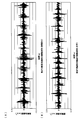
- FIG. 22 shows a vibration waveform of the rolling bearing in which the outer ring is damaged.
- the vibration amplitude is modulated every time the rolling element passes through the damaged part of the outer ring.
- the vibration generated by damage is very small. Therefore, such vibration is caused by vibration generated by rotation of the bearing or other factors generated around the bearing.
- the S / N ratio becomes very poor due to being buried in vibration.
- the state of the bearing cannot be diagnosed by simply detecting the amplitude modulation.
- a method of improving the SN ratio by performing special signal processing on the vibration signal, or measuring an AE (acoustic emission) signal has been proposed.
- Patent Document 1 vibration of a low-speed rotating machine is detected by a bearing portion, and the vibration detection signal is subjected to band-pass filter processing to obtain a spectrum domain power at the time of bearing damage. Extract the eigenband component representing the increasing abnormal state, calculate the crest factor of this eigenband component, calculate the crest factor of the calculated crest factor, and compare it with the preset threshold value to diagnose the abnormality of the low-speed rotating machine A method of performing is proposed.
- a vibration time waveform that is raised to a power and exceeds a threshold is counted as an event (abnormality). For example, the count number at a certain time interval such as one hour or one day is calculated.
- There is a method of quantifying the abnormality of the bearing by monitoring the increase / decrease and the increase / decrease of the count number per one rotation.
- one occurrence of the AE signal is counted as one event, for example, increase / decrease of the count number at regular time intervals such as one hour or one day, or the count number per one rotation.
- the event duration is integrated with one occurrence of the AE signal as one event, for example, the increase or decrease of the event integration time at regular time intervals such as 1 hour or 1 day, or the event integration time per rotation.
- the bearing abnormality by monitoring the increase and decrease.
- the AE signal can detect a very small change in the equipment state, but reacts sensitively, so it cannot be said to be abnormal. Even if it exists, there are many overdetections that determine that it is abnormal, and there is a problem that it is difficult to handle in measurement and diagnosis.
- the reference value for determining the occurrence of an event is usually a fixed value calculated from the data based on the normal signal collected during the initial adjustment period of the rotating machinery equipment. Many.
- the reference value is a fixed value and a failure diagnosis of a bearing or the like is performed by comparing the reference value and the signal
- the signal level changes when the rotational speed of the rotating machine equipment changes and a load fluctuation occurs. There is a problem that an event cannot be correctly judged and a malfunction is induced.
- the abnormal cycle time of a bearing that occurs once per rotation is about 60 msec, and the period can be detected by measuring about 1 second even if data acquisition for multiple rotations is considered.
- the cycle in which the abnormality occurs becomes longer as the rotational speed becomes lower. Therefore, the abnormal cycle time of the bearing that occurs once in one rotation in the rotating facility of 1 rpm is about 60 sec, Considering the data acquisition, it is necessary to measure about 1000 seconds.
- the abnormal cycle time of the bearing that occurs once per rotation is about 600 seconds, and taking data acquisition for a plurality of rotations requires measurement of about 10,000 seconds.
- the sampling frequency is 1 kHz to 3 kHz.
- the number of data required for each rotation speed may be 1000 data for 1000 rpm, but 1000000 data for 1 rpm and 10000000 data for 0.1 rpm.
- the data capacity is 2 kbytes at 1000 rpm, 2 Mbytes at 1 rpm, and 20 Mbytes at 0.1 rpm. There is a problem that it takes time.
- Patent Document 2 the collected vibration signal is divided at a preset time interval, and the frequency of the vibration signal is analyzed for each divided section to obtain a power spectrum.
- a signal processing method for improving the S / N ratio by discriminating a signal at a normal location and a signal at an abnormal location from a power value is disclosed.
- the average power spectrum in the remaining divided sections obtained by removing the divided section having a large total power value is obtained. It is regarded as a power spectrum at a normal location, and an abnormal vibration is detected by obtaining a ratio between the average power spectrum and the power spectrum for each divided section.
- the present invention has been made in view of the above problems, and allows an administrator to intuitively grasp the state of failure of a rolling bearing or a sliding bearing attached to a rotating machine facility, without storing a large amount of measurement data.
- it is an issue to reliably perform failure diagnosis.
- it is an object to make it possible to accurately diagnose the state of the bearing even when the disturbance signal is large and the S / N ratio of the signal component indicating abnormality or damage of the bearing is very low.
- a diagnostic system for a bearing in a rotary machine facility A sensor for detecting the occurrence of damage attached to a fixed member of the bearing; A monitoring and diagnosis device connected to the sensor; A diagnostic notification means for connecting with the monitoring diagnostic device and displaying an abnormal state in percentage;
- the monitoring and diagnosis apparatus includes: A storage unit for storing measurement data detected by the sensor; A reference level calculation unit that calculates an abnormality determination reference level based on the measurement data stored in the storage unit; One rotation time or intermittent operation time of the rotating shaft supported by the bearing is equally divided into a plurality of sections, and the abnormality determination reference level is compared with the measurement data of each section, for each section. And a determination unit for determining whether or not there is an abnormality is provided.
- One rotation time or one intermittent operation time of the rotating shaft supported by the bearing is divided into 100 sections for display as a percentage.
- the time required for one rotation of the rotating shaft supported by the bearing of the rotating equipment or one intermittent operation of the intermittent operation equipment is divided into 100 sections, and an event is generated for each section. (Abnormality occurrence) is diagnosed and the number of sections where an abnormality has occurred in the rolling bearing is calculated. For this reason, the number of sections in which the abnormality occurs is a percentage of the time (width) of the bearing abnormal state with respect to one rotation time or one intermittent operation time, and the facility administrator looks at the number of sections in which the abnormality has occurred.
- the time occupied by the abnormal state of the bearing per one rotation time or one intermittent operation time can be intuitively recognized.
- the abnormality determination is performed using the abnormality occurrence count of the signal such as AE (Acoustic Emission) or the integrated value of the abnormality occurrence time as in the prior art, it cannot be said that the abnormality is caused by the continuous AE occurrence phenomenon.
- one rotation time or one intermittent operation time is divided into a plurality of sections, and the abnormality of the rolling bearing is determined based on the number of sections in which the abnormality has occurred. Therefore, overdetection can be suppressed.
- the number of rotations of the rotating shaft of the rotating machine equipment supported by the bearing is preferably 0.1 rpm or more and 300 rpm or less, more preferably 0.1 rpm or more and 150 rpm or less, and further preferably 0.1 rpm or more and 100 rpm or less.
- the bearing is preferably a rolling bearing or a sliding bearing.
- the sensor is any one of a vibration acceleration pickup, an acoustic emission (AE), an ultrasonic sensor, and a sound detection sensor fixed to the bearing housing.
- the abnormality determination reference level is set to a constant multiple of the average value of the measurement data stored in the storage unit for each rotation or one intermittent operation of the rotating shaft supported by the bearing. is doing. As described above, the abnormality determination reference level is set for each rotation or one intermittent operation of the rotating shaft supported by the bearing, so that the rotation speed and load of the rotating machine equipment to which the bearing is attached are changed. In addition, it is possible to determine the failure of the bearing in accordance with the rotational speed and load.
- a diagnostic parameter calculator that calculates a diagnostic determination parameter that is the number of sections in which an abnormality has occurred; It is preferable that a simple diagnosis determination unit that compares the diagnosis determination parameter with a predetermined abnormality determination criterion to determine whether or not there is an abnormality is provided.
- the diagnosis parameter is calculated by the diagnosis parameter calculation unit, and the diagnosis determination parameter is compared with the abnormality determination reference value by the diagnosis determination unit.
- the diagnosis determination parameter is compared with the abnormality determination reference value by the diagnosis determination unit.
- the determination unit of the monitoring / diagnostic apparatus sets an abnormal section only when the section in which abnormality is determined is a set number of adjacent sections within 2 to 10, and abnormal determination in a section less than the set number is an abnormality that is removed as noise. It is preferable that a generation section continuation determination unit is provided.
- the determination unit of the monitoring diagnostic apparatus includes an averaging processing unit that averages the diagnosis determination parameters for a plurality of rotations or a plurality of intermittent operations.
- an averaging processing unit that averages the diagnosis determination parameters for a plurality of rotations or a plurality of intermittent operations.
- the abnormality determination criterion to be compared with the diagnosis determination parameter is set at a plurality of levels such as a caution level and a danger level.
- a plurality of abnormality determination criteria are provided, and the occurrence of abnormality is diagnosed by comparing each level of the caution level and the danger level with the diagnosis determination parameter, so that the bearing failure can be diagnosed in more detail.
- the determination unit of the monitoring and diagnosis apparatus calculates the degree of coincidence of the determination results of occurrence of abnormalities for each distinction by shifting the abnormal cycle reference position of the abnormality determination result table for a plurality of rotations or a plurality of intermittent operations. It is preferable to include a synchronous search processing unit that searches for an abnormal cycle reference position where the frequency becomes high and automatically calculates an abnormal cycle from the abnormal cycle reference position.
- the synchronous search processing unit gradually shifts the abnormal cycle reference position and creates a correction table based on the abnormality determination result table.
- the degree of coincidence of the determination result of occurrence of abnormality for each section of the correction table is calculated for each abnormal period reference position, and the abnormal period reference position in the correction table having the highest degree of coincidence is detected.
- An abnormal period in which an abnormality occurs in the bearing is calculated from the thus determined abnormal period reference position.
- the present invention enables accurate fault diagnosis of the bearing state even when the disturbance signal is large and the S / N ratio of the signal component indicating abnormality or damage of the bearing is very low.
- the second invention and the third invention are provided.
- a second invention is a diagnostic system for a bearing in a rotary machine facility, A sensor for detecting the occurrence of damage attached to a fixed member of the bearing; A monitoring and diagnosis device connected to the sensor; A diagnostic notification means for connecting to the monitoring diagnostic device and displaying a diagnostic result;
- the third invention is A bearing diagnosis system for rotating machinery equipment, A sensor for detecting the occurrence of damage attached to a fixed member of the bearing; A monitoring and diagnosis device connected to the sensor; A diagnostic notification means for connecting to the monitoring diagnostic device and displaying a diagnostic result;
- the monitoring and diagnosis apparatus includes: A storage unit for storing a signal waveform detected by the sensor; A signal waveform calculation unit stored in the storage unit;
- the degree of kurtosis is obtained from a waveform signal detected by a vibration sensor or the like, an abnormality occurrence state is indicated by the degree of kurtosis, and whether the abnormality is sudden disturbance vibration or It is possible to judge whether it is due to damage. That is, kurtosis is used as an index representing the degree to which the frequency spectrum of the waveform signal detected by the vibration sensor has a peak at a specific frequency. In the normal distribution, the value of the kurtosis is small, and the distribution having a sharper shape than the normal distribution has a larger value of the kurtosis. Therefore, when the sharpness is high, it indicates that the vibration having periodicity is occurring.
- the sharpness when the sharpness is high, it indicates that the vibration generated by the bearing damage is included.
- the vibration when the kurtosis is low, the vibration is sudden disturbance vibration, so it can be determined that the vibration is caused by a factor other than the bearing damage.
- any one of the first to third inventions Calculated from the bearing device information and / or the rotation speed information, and calculated by the calculation abnormality occurrence period or an integer multiple of the calculation abnormality occurrence period, which is different for each abnormality cause, by the synchronous search processing unit or the calculation unit.
- An abnormality period is compared, and when the degree of coincidence between the calculation abnormality occurrence period or an integer multiple of the calculation abnormality occurrence period and the abnormality period is high, an abnormality caused by the cause corresponding to the calculation abnormality occurrence period is present in the bearing. It is preferable to include a determination unit that diagnoses the occurrence.
- the cause of the abnormality is at least one of inner ring damage, outer ring damage, and rolling element damage
- it is an abnormal metal contact of the rotating shaft that occurs once or a plurality of times in one rotation or one intermittent operation.
- the abnormal metal contact is a metal contact of the rotating shaft due to abnormal vibration of the rotating shaft, a metal contact of the rotating shaft due to an oil film abnormality of the slide bearing, or the like.
- the abnormality occurrence cycle differs for each cause of abnormality.
- the abnormality occurrence cycle corresponding to each abnormality cause is calculated from the bearing device information and the rotation speed information. Further, in the case of a slide bearing, an abnormality occurrence cycle corresponding to the rotation speed is caused by shaft contact.
- the cause of the abnormality corresponding to the calculated abnormal occurrence period has occurred in the bearing. Diagnose. In this way, the abnormality occurrence period corresponding to each abnormality cause is calculated, and the abnormality cause occurring in the bearing is calculated by comparing the abnormality abnormality period with the calculation abnormality occurrence period or an integer multiple of the calculation abnormality occurrence period. Can be identified.
- the movable type combining the sensor, the monitoring diagnostic device, and the diagnostic notification unit, or the diagnostic notification unit may be wirelessly connected to the monitoring diagnostic device to be portable.
- the diagnostic system By making the rolling bearing diagnostic system movable, the diagnostic system can be carried, and a sensor can be attached to the rolling bearing to be diagnosed to diagnose a failure of the rolling bearing. Further, by wirelessly connecting the monitoring diagnostic apparatus and the diagnostic communication means, the administrator can carry the diagnostic communication means and know the state of the low-speed rotating machine equipment.
- the time required for one rotation of the rotating shaft supported by the bearing of the rotating equipment or one operation of the intermittent operation equipment is divided into approximately 100 sections, The occurrence of abnormality is diagnosed for each section, and the number of sections in which the abnormality has occurred is calculated. For this reason, the number of sections in which the abnormality occurs is a percentage of the time (width) of the bearing abnormal state with respect to one rotation time or one intermittent operation time, and the facility administrator looks at the number of sections in which the abnormality has occurred.
- the time occupied by the abnormal state of the bearing per rotation time can be intuitively recognized.
- the determination unit creates a correction table by gradually shifting the abnormal cycle reference position from the abnormality determination result table that is the determination result of occurrence of abnormality in each section for a plurality of rotations or a plurality of intermittent operations, and the degree of coincidence becomes highest.
- An abnormal cycle reference position is detected, and an abnormal cycle in which an abnormality occurs in the bearing is calculated from the abnormal cycle reference position.
- Anomaly occurrence period is different for each cause of anomaly, and it is generated in the bearing by comparing the anomaly period with the calculated anomaly occurrence period calculated for each anomaly cause or an integer multiple of the calculated anomaly occurrence period. It is possible to identify the cause of abnormality.
- the abnormality occurrence state can be visually displayed by displaying the signal waveform detected by the sensor as a spectrum waveform having a sharpness.
- the present invention is realized using an rms value calculation circuit and an equivalent peak calculation circuit. be able to.
- the data processing device does not require a large capacity data storage means or a high speed arithmetic unit. Furthermore, it is possible to diagnose and determine the cause of occurrence of an abnormality in the rolling bearing.
- FIG. 1 It is a block diagram of the bearing diagnostic system which shows 3rd Embodiment. It is a block diagram of the bearing diagnostic system which shows the modification of 3rd Embodiment. It is a block diagram of the monitoring diagnostic apparatus which shows 4th Embodiment. It is a block diagram of the monitoring diagnostic apparatus which shows 5th Embodiment.
- (A) (B) is a graph which shows the vibration waveform of the bearing obtained with the conventional diagnostic apparatus.
- (A), (B), and (C) are graphs showing the kurtosis degrees Ks and Ki of the bearing obtained in the fourth embodiment. It is a figure which shows the frequency spectrum Ss obtained in 4th Embodiment. It is a graph which shows a prior art example.
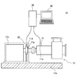
- the bearing diagnosis system 10 for a rotating machine facility diagnoses the state of a rolling bearing 11a of a low-speed rotating motor, which is one of rotating machine facilities 11 installed in a steel facility factory.
- the diagnostic system 10 includes a damage occurrence detection sensor 20 mounted on a rolling bearing 11 a of a low-speed rotating machinery facility 11 that continuously rotates a plurality of rotations.
- the monitor / diagnosis apparatus 30 connected, the monitor 40 which comprises the diagnostic notification means connected with the monitor / diagnosis apparatus 30, and the tachometer 21 which measures the rotation speed of the motor are provided.
- the damage occurrence detection sensor 20 is an AE sensor that detects acoustic emission, and is fixed to a bearing housing 11d of a low-speed rotation motor 11c provided on the foundation frame 11b with screws.
- the tachometer 21 is attached to the load side bearing mount 11e.
- the attachment position of the damage occurrence detection sensor 20 is not limited to the above position. Further, the rotational speed information of the motor may be stored in advance in the microcomputer 34 of the monitoring / diagnosis apparatus 30 without attaching the tachometer 21.
- a vibration acceleration pickup that detects vibration, an ultrasonic sensor, or a sound detection sensor may be used instead of the damage occurrence detection sensor 20.
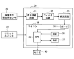
- the monitoring / diagnosis device 30 includes a signal amplification circuit 31, a filter circuit 32, a detection circuit 33, and a microcomputer 34.
- the signal amplifier circuit 31 is an amplifier that amplifies the signal measured by the damage occurrence detection sensor 20.
- the filter circuit 32 is a band-pass filter that removes noise components from the signal amplified by the signal amplifier circuit 31. In the case of the vibration acceleration pickup, the filter circuit 32 is a filter that passes a band of 1 kHz to 20 kHz. When an AE sensor is used, a filter that passes a band of 50 kHz to 500 kHz is used.
- the detection circuit 33 detects (envelope processing) the signal from which noise has been removed by the filter circuit 32. Depending on the signal, the detection circuit 33 may not be provided, and in the case of a vibration signal, a power process may be performed instead of detection.
- the microcomputer 34 includes a CPU 35, a ROM 36, a RAM 37, and a port 38.
- the port 38 of the microcomputer 34 A / D converts the signal from the detection circuit 33 at a predetermined sampling period.
- the ROM 36 and the RAM 37 constitute a storage unit.
- the RAM 37 stores an abnormality determination result table calculated by the CPU 35 and temporarily stores data calculated by the CPU 35.
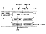
- the ROM 36 stores the operation of the CPU as software. As shown in FIG. 3, the CPU 35 includes a reference level calculation unit 50 and a determination unit 59.
- the determination unit 59 includes a diagnostic parameter calculation unit 51, an abnormality occurrence section continuation determination unit 52, an averaging processing unit 54, Each unit includes a simple diagnosis determination unit 55, a synchronous search processing unit 56, and a cause diagnosis processing unit 57.
- the CPU 35 reads out the software from the ROM 36 and executes it to operate each unit.
- the reference level calculation unit 50 receives the rotation speed information of the motor from the tachometer 21 and calculates a time required for one rotation of the motor (one rotation time).
- the time data output from the port 38 is stored in the RAM 37 for a time length of one or more rotations of the motor.
- the rotation number information of the motor 11c may be stored in advance in the reference level calculation unit 50, and one rotation time may be calculated using the rotation number information.
- the diagnostic parameter calculation unit 51 divides one rotation time into equal intervals of 1/100, and sets each section as section No. 1 to Section No. 100.
- Section No. 1 in the order of the measured data for one rotation time length. 1 to Section No. Sort into 100 sections.
- section no. 1 to Section No. It is determined whether there is data exceeding the abnormality determination reference level E in the data allocated to each of the 100 sections. For example, in FIG. 6, 7 and 8 are abnormal occurrence sections because the data exceeds the abnormality determination reference level E.
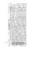
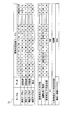
- FIG. 5 is an example of the abnormality determination result table T1, and shows whether or not an abnormality has occurred for each section with respect to the rotation of the motor from the latest to nine rotations. Further, the total value of the number of sections in which an abnormality has occurred within one rotation time is calculated and used as the diagnosis determination parameter A. That is, the diagnosis determination parameter A is the number of abnormality occurrence sections (Y) within one rotation time length.
- the abnormality occurrence section continuation determination unit 52 detects a section in which an abnormality occurs continuously from the table T1 of the abnormality determination result obtained by the diagnosis parameter calculation unit 51. For example, as shown in FIG. 6-No. In FIG. 8, the abnormality occurs continuously for three sections, and the number of consecutive sections is three. In addition, section No. 11-No. 14 is the number of consecutive occurrence sections is four. On the other hand, the section No. 98 is a section where an abnormality has occurred. In 97 and 99, no abnormality has occurred, and the number of consecutive occurrence sections is one.
- the continuity determination interval number k may be selected from 2 to 10.
- the abnormality occurrence section continuation determination unit 52 creates an abnormality determination result table T2 that is corrected by determining continuity for each rotation, and stores it in the RAM 37.
- the diagnosis determination parameter determination value Ax is averaged every rotation and is a moving average value. That is, as shown in FIG. 8, when the averaging processing unit 54 receives a table of abnormality determination results before two rotations, a diagnosis determination parameter determination value Ax1 is obtained from the diagnosis determination parameters An before nine rotations and two rotations before. When the table before one rotation is received, the diagnosis determination parameter determination value Ax2 is obtained from the diagnosis determination parameter An from one rotation before eight rotations. When the most recent table is received, the most recent diagnosis determination parameter from seven rotations before The diagnosis determination parameter determination value Ax3 is obtained from An.
- the simple diagnosis determination unit 55 stores the attention level determination reference value as 5, for example, and the danger level determination reference value as 15, for example.
- the diagnosis determination parameter determination value Ax is compared with the determination reference value every rotation, and if the diagnosis determination parameter determination value Ax is larger than each determination reference value, a failure of a caution level and a danger level occurs in the rolling bearing 11a. It is determined that there is.
- the simple diagnosis determination unit 55 displays the determination result on the monitor 40.
- the simple diagnosis determination unit 55 determines that a failure of the attention level or the danger level has occurred
- the synchronization search processing unit 56 and the cause diagnosis processing unit 57 identify the cause of the abnormality of the rolling bearing 11a.
- the synchronous search processing unit 56 and the cause diagnosis processing unit 57 identify inner ring damage, outer ring damage, and rolling element damage as an abnormality of the rolling bearing 11a.
- an abnormality occurs at a different cycle (abnormality generation cycle) depending on the damaged portion.
- the synchronous search processing unit 56 uses the abnormality determination result table T2 to obtain the abnormal cycle Bm that is closest to the rotation cycle of the rotating machine, and the cause diagnosis processing unit 57 determines the cause of the failure from the relationship between the abnormal cycle Bm and the abnormality occurrence cycle. I have identified.
- the synchronous search processing unit 56 automatically detects the abnormal cycle reference position and determines the abnormal cycle Bm.
- the abnormal period Bm is a period obtained by multiplying the abnormality generation period in which an abnormality occurs due to damage to the rolling bearing 11a by m, and the value of m is a value that makes the abnormal period Bm closest to the rotation period of the rotating machine.
- the abnormal cycle Bm is not necessarily synchronized with the rotation cycle of the rotating machine, and the abnormal cycle Bm may or may not be the same cycle as the rotation cycle of the rotating machine. A method for obtaining the abnormal period Bm will be described below.
- the correction table Ta is created using the abnormality determination result table T2 obtained by the averaging processing unit 54.
- the abnormality determination result table T2 is created so as to be 100 sections based on the rotation cycle reference position that divides the rotation cycle.
- the abnormality cycle Bm is based on the abnormality determination result table T2 in the past direction. When it is assumed that the period is 101 sections long by one section, a correction table Ta having 100 sections is created.
- the abnormality determination result table T2-0 to the table T2-4 are arranged, and the section No. of the latest table T2-4 is arranged.
- the abnormal period Bm is divided in the past direction. Since the abnormal period Bm is assumed to be 101, the section No. of the table T2-4 is past in the past direction.
- 101 section up to 100 is abnormal cycle BmA
- 101 section up to 99 is abnormal cycle BmB
- 101 section up to 98 is abnormal cycle BmC
- 101 section up to 97 is the abnormal period BmD.
- the abnormal cycle reference position is set as the section No. in table T2-4. 100, section No. of table T2-3. 99, section No. of table T2-2. 98, section No. of table T2-1. 97, and the abnormal cycle reference position is defined as the 100th section of the correction table Ta, and 100 sections are extracted from the abnormal cycle reference position in the past direction, and the correction table Ta-4 to the abnormal cycle BmA, BmB, BmC, BmD Ta-1. At this time, for example, the section number of table T2-3. 100 etc. do not enter the correction table Ta.
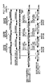
- FIG. 10 is a diagram showing from which section of the original table T2 the correction tables Ta-4 to Ta-1 are configured.
- FIG. 9 shows a case where the search interval difference in FIG. Similarly, when the rotation time is assumed to be 102 or 103 in the past direction by 2 or 3 sections longer in the table T2, that is, when the search section difference in FIG. Ask for.
- the search section difference is set to 0 to 10 to obtain the correction table Ta.
- the search interval difference may be set to 0-20.
- the search section difference 0 is the case where the original table T2 and the correction tables Ta-4 to Ta-1 are the same, and shows the case where the rotation period and the abnormal period Bm coincide as shown in FIG.
- the total matching degree h is calculated for each of the correction tables Ta having the search section differences of 0 to 10 thus obtained.
- an abnormality occurrence (Y) determination interval number k which is the number of intervals in which an abnormality has occurred is obtained, and an interval No. Section Nos. 1 to 100 ⁇ f which is the sum of the different matching degrees f is obtained, and the total matching degree h is obtained from the equation (8).
- Total matching degree h ⁇ f ⁇ k equation (8)
- the total matching degree h is obtained for each of the correction tables Ta when the search section difference is 0 to 10, and the correction table Ta having the highest total matching degree h is selected.
- the abnormal cycle Bm is determined from the abnormal cycle reference position to the next abnormal cycle reference position in the selected correction table Ta.
- the cause diagnosis processing unit 57 specifies the cause of the failure of the rolling bearing 11a using the abnormal cycle Bm obtained by the synchronous search processing unit 56.
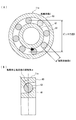
- FIG. 13 shows the structure of the rolling bearing 11a, an outer ring 60 fixed to the rotating machine case, an inner ring 61 fixed to the shaft of the rotating machine and arranged concentrically with the outer ring, and between the outer ring 60 and the inner ring 61. It consists of a plurality of spherical rolling elements 62 that are arranged to roll freely.
- Possible causes of failure of the rolling bearing 11a include inner ring damage, outer ring damage, and rolling element damage.
- the abnormality occurrence period for each damage is expressed by the equation (11) according to the geometric dimension of the rolling bearing 11a. It is calculated
- the abnormality occurrence period Tin when the inner ring is damaged is expressed by Expression (11)
- the abnormality generation period Tout when the outer ring is damaged is expressed by Expression (12)
- the abnormality generation period Tball when the rolling element is damaged is expressed by Expression (13).
- the rotation frequency fr is the number of rotations (rpm) from the tachometer divided by 60.
- These abnormality occurrence cycles Tin, Tout, and Tball are multiplied by s as a calculation abnormality occurrence cycle Tx, and calculation is performed by changing s from 1 to 10.
- the calculation abnormality occurrence period Tx is the calculation result time Tin1 to Tin10 of Tin ⁇ s, the calculation result time Tout1 to Tout10 of Tout ⁇ s, and the calculation result time Tball1 to Tball10 of Tball ⁇ s.
- the abnormal cycle Bm obtained by the synchronous search processing unit 56 is compared with the calculated calculation abnormality occurrence cycle Tx, that is, Tin1 to Tin10, Tout1 to Tout10, and Tball1 to Tball10.
- the damage corresponding to the calculation abnormality occurrence period Tx is diagnosed as an abnormality cause, and these diagnosis results are displayed on the monitor.
- a predetermined time width is determined around the abnormal period Bm, and when the value of the calculated abnormality occurrence period Tx is within the time width, the damage corresponding to the calculated abnormality occurrence period Tx is diagnosed as the cause of the abnormality.
- Tin 10 is within a predetermined time width centered on the abnormal period Bm, it is diagnosed that the inner ring is damaged.
- Tin 10 and Tout 8 are within a predetermined time width centered on the abnormal period Bm, it is diagnosed that the inner ring and the outer ring are damaged.
- a sliding bearing may be attached to the rotary machine equipment 11.
- the calculation abnormality occurrence period Tx is obtained by 1 / fr, and the calculation abnormality generation period Tx
- the cause of the abnormality is diagnosed by comparing the abnormal period Bm.
- the abnormality occurrence period Tn is obtained by one rotation period / number of abnormality occurrences per rotation (p), and the abnormality occurrence period Tn
- the cause of the abnormality is diagnosed by comparing p times the number of times with the abnormal period Bm.
- the time required for one rotation of the rolling bearing 11a of the equipment rotating at a low speed or one operation of the intermittent operation equipment is divided into about 100 sections, and the occurrence of abnormality (occurrence of abnormality) is diagnosed for each section.
- the number of sections in which an abnormality has occurred is calculated.
- the number of sections in which the abnormality occurs is a percentage of the time (width) of the bearing abnormal state with respect to one rotation time or one operation time, and the facility administrator looks at the number of sections where the abnormality has occurred,
- the time occupied by the abnormal state of the bearing per rotation time can be intuitively recognized.
- the synchronization search processing unit 56 and the cause diagnosis processing unit 57 gradually shift the abnormal cycle reference position from the abnormality determination result table that is the determination result of abnormality occurrence in each section for a plurality of rotations or a plurality of intermittent operations. And the abnormal cycle reference position with the highest degree of coincidence is detected. An abnormal period in which an abnormality occurs in the bearing is calculated from the thus determined abnormal period reference position. The abnormality occurrence period is different for each abnormality cause, and the degree of coincidence can be determined by comparing the abnormality abnormality period with the calculation abnormality occurrence period calculated for each abnormality cause or an integer multiple of the calculation abnormality occurrence period. When there is a high calculation abnormality occurrence cycle, it can be diagnosed that an abnormality cause corresponding to the calculation abnormality occurrence cycle is occurring in the bearing.
- FIG. 14 shows a second embodiment.
- the second embodiment is an embodiment of the first invention.
- one operation operation of the rotating facility is less than one rotation
- the rolling bearing 11a of the intermittent operation facility that repeatedly performs the operation is set as a diagnosis target.
- An example of the intermittent operation facility is a ladle turret that is one of steel facilities. The ladle turret repeats the operation of 1/2 rotation at a low speed of 1 rpm per operation.
- a limit switch 22 is connected to a microcomputer 34 instead of the tachometer 21. The limit switch 22 causes the CPU 35 to detect operation start and operation stop in the intermittent operation facility.
- the reference level calculation unit 50 of the CPU 35 stores the signal from the damage occurrence detection sensor 20 in the RAM 37 for a length equal to or longer than one intermittent operation time.
- the diagnostic parameter calculation unit 51 obtains a one-time intermittent operation average value by dividing the total of one-time intermittent operation time length data stored in the RAM 37 by the number of data.
- the abnormality determination reference level E is obtained from the one-time intermittent operation average value ⁇ m. Further, the one-time intermittent operation time is divided into 100 sections, and an abnormality determination result table is created by comparing with the abnormality determination reference level E for each section.
- the averaging processing unit 54 obtains the diagnosis determination parameter A and the determination value of the diagnosis determination parameter A using the abnormality determination result table for the latest j times of intermittent operation and the table obtained in the same equipment operation state. Yes.
- the same equipment operation state means that in the case of a motor that rotates 1/2 turn in one operation and repeats 1/2 turn operation as A ⁇ B ⁇ A ⁇ B ⁇ A ⁇ B, The operation state of B is said.
- the predetermined processing is performed using the tables obtained in the A operation state or the tables obtained in the B operation state.
- the correction table Ta is obtained using tables obtained in the same equipment operation state.
- the number of sections in which the abnormality has occurred is expressed as a percentage of the time (width) of the bearing abnormal state with respect to one operation time.
- the manager can intuitively recognize the time occupied by the abnormal state of the bearing per operation time by looking at the number of sections in which the abnormality has occurred.
- FIG. 15 shows a third embodiment.
- the third embodiment is an embodiment of the first invention.
- the diagnosis system 10 according to the third embodiment is a movable type in which the monitoring diagnosis device 30 and the monitor 40 are combined.
- the monitoring / diagnosis device 30 and the monitor 40 are, for example, laptop computers.
- the monitoring / diagnosis device 30 is connected to the damage occurrence detection sensor 20, and the damage occurrence detection sensor 20 is attached to the bearing housing 11d with a magnet.
- a dedicated jig may be attached to the damage occurrence detection sensor 20, and the sensor may be fixed by manually pressing the sensor against the bearing housing 11d.
- the damage detection sensor 20 is fixed to the bearing housing 11d in advance with a screw or an adhesive, and a portable measuring instrument is connected to the sensor for diagnosis. Also good.
- the diagnostic system 10 portable as a movable type, it is possible to carry out the diagnostic system 10 to the rolling bearing 11a to be diagnosed and perform an abnormality diagnosis.
- symbol is attached
- FIG. 16 shows a modification of the third embodiment, in which a diagnostic device 50 in which a damage detection sensor 20, a monitoring diagnostic device 30, and a tachometer 21 are integrated is fixed to a rolling bearing 11a. Further, the monitoring / diagnosis apparatus 30 is provided with a communication unit, and is wirelessly connected to a mobile phone 41 constituting the diagnosis notification unit. The diagnosis device 50 transmits the diagnosis result obtained by the simple diagnosis determination unit 55 to the mobile phone 41. When the administrator carries the mobile phone 41, the diagnosis result of the rotating machine equipment 11 can be received even at a location away from the rotating machine equipment 11. In addition, since another structure and effect are the same as that of 1st Embodiment, the same code
- FIG. 17 shows a fourth embodiment.
- the fourth embodiment is an embodiment of the second invention.
- a vibration sensor 61 is attached to a rolling bearing unit 62 on one side of a roll rotating at 46 rpm of a rotating machine facility, and the state of the bearing is monitored.
- the output signal of the vibration sensor 61 is amplified to a predetermined level by the amplifier 63, and then transmitted to the A / D converter 64.
- the output signal of the A / D converter 64 is transmitted to the arithmetic processing unit 65, and the calculation is performed.
- the processing device A is connected to an output device 66 comprising a diagnostic notification means such as a monitor.
- the arithmetic processing unit 65 includes a storage device 71 connected to an A / D converter 64, a waveform dividing unit 72, a frequency spectrum calculating unit 73, a frequency spectrum sum calculating unit 74, a frequency spectrum sum waveform signal generating unit 75, and a waveform signal.
- the A / D converter 64 discretizes the vibration waveform at a sampling frequency of 50 kHz
- the arithmetic processing unit 65 calculates the kurtosis degree Ks from the discrete waveform, and the calculated kurtosis degree Ks by the output unit 66 in the past.
- an alarm is displayed when the kurtosis Ks reaches a predetermined level.
- the rotational speed of the bearing unit 62 whose state is monitored in advance is input to the arithmetic processing unit 65, and a vibration waveform of one rotation or more of the bearing can be stored in the storage device 71.
- a waveform signal Sx is created by arranging Sj by the waveform signal creation means 75 of the frequency spectrum sum.
- the frequency spectrum calculating means 76 of the waveform signal calculates the frequency spectrum Ss of the waveform signal Sx, and the sharpness calculating means of the frequency spectrum calculates Equation (14) to obtain the kurtosis Ks.
- xi represents each spectrum of the frequency spectrum Ss, and xa is an average value thereof.
- N 0 is the number of xi.
- the abnormality cause determination means 78 is inputted in advance with the number of rolling elements Z of the rolling bearing of the bearing unit 12, the diameter d of the rolling elements, the pitch circle diameter D, and the contact angle ⁇ between the rolling elements 62 and the transfer surface. Together with the speed, the period of occurrence of anomaly when damage occurs is calculated. Further, from the peak frequencies fs1, fs2, fs3,... Of the frequency spectrum Ss obtained by the frequency spectrum calculating means 76 of the waveform signal, the corresponding periods Ts1, Ts2, Ts3,. If they match, it is determined that the abnormality has occurred in the rolling bearing of the bearing unit 12.
- a vibration waveform indicating the state of the bearing is detected by the vibration sensor 61, the detected vibration waveform is collected and stored, and transmitted to the arithmetic processing unit 65 via the amplifier 63 and the A / D converter 64.
- the storage unit 71 stores the vibration waveform
- the waveform dividing means 72 divides the stored waveform into n sections.
- the time length of the divided section is tmsec, it is desirable to determine the divided section function n according to the rotational speed of the bearing. That is, if the division function n is set in accordance with the number of rotations of the bearing, a vibration waveform having a length of time corresponding to one rotation, two rotations, three rotations,...
- the divided sections are (1) a section where vibration close to a normal state occurs, (2) a section where disturbance vibration is added to vibration close to a normal state, and (3) abnormalities. It can be roughly divided into a section in which vibration is generated and (4) a section in which disturbance vibration is added to abnormal vibration.
- the frequency spectrum is the lowest in the section where the vibration close to the normal state (1) occurs, and the frequency spectrum is the highest in the section where the disturbance vibration is added to the abnormal vibration (4). Therefore, when the sum of the frequency spectra is obtained, it can be determined whether the divided section includes abnormal vibrations, disturbance vibrations, or both depending on the magnitude of the sum of the frequency spectra Fjk.
- Fjk when obtaining the sum of the frequency spectrum Fjk, it is desirable to obtain the sum by limiting to a spectrum in a specific frequency range.
- the vibration generated by damage to the rolling bearing is a relatively high frequency vibration of 1 kHz to 40 kHz. For example, it is clear that a vibration of several tens of Hz is a disturbance vibration of a low frequency.
- the vibration of a rotating machine such as a bearing is generated with rotation and thus has periodicity.
- the disturbance signal is generated suddenly and randomly, there is no periodicity. For this reason, when the frequency of the waveform signal Sx is analyzed, a spectrum having a peak at a specific frequency is obtained in the vibration generated by the bearing abnormality, whereas the disturbance vibration generated at random has a shape in which the frequency spectrum is dispersed.
- the kurtosis degree Ks is used as an index representing the degree to which the frequency spectrum Ss of the waveform signal Sx has a peak at a specific frequency.
- the kurtosis is 3, and as the distribution has a sharper shape than the normal distribution, the value of the kurtosis increases. Therefore, when the kurtosis Ks is high, it indicates that vibration having periodicity is generated, and therefore vibration generated by damage to the bearing is included. Conversely, when the kurtosis Ks is low, the vibration is a sudden disturbance vibration, so it can be determined that the vibration is caused by a factor other than the bearing damage. Therefore, information for determining the state of the bearing can be obtained by displaying the value of the kurtosis Ks and its change with time as a trend graph.
- FIG. 18 shows a fifth embodiment.
- the fifth embodiment is an embodiment of the third invention. Similar to the fourth embodiment, a vibration sensor 61 is attached to the rolling bearing unit 62 on one side of a roll rotating at 46 rpm to monitor the state of the bearing. The output signal of the vibration sensor 61 is amplified to a predetermined level by the amplifier 63, passes through a bandpass filter 80 having a passband of 1 kHz to 20 kHz, and is then transmitted to the A / D converter 64.
- an analog filter is used as the bandpass filter 80, but after the A / D converter 64 stores the vibration waveform after A / D conversion, the stored vibration waveform passes through the digital filter. It is possible to extract a component of 1 kHz to 20 kHz.
- An output signal from the A / D converter 64 is output to the arithmetic processing unit 67.
- the arithmetic processing unit 67 includes a storage device 71 and a waveform dividing unit 72, an rms value calculating unit 81 connected to the waveform dividing unit 72, and an rms waveform signal generating unit 82.
- the rms waveform signal creation means 82 is connected to the frequency spectrum calculation means 76 of the waveform signal, and the frequency spectrum calculation means 76 of the waveform signal is connected to the frequency spectrum kurtosis calculation means 77 and the abnormality cause determination means 78.
- the kurtosis is calculated by the frequency spectrum kurtosis calculation means 77 from the discrete waveform of the frequency spectrum calculated by the frequency spectrum calculation means 76 of the waveform signal, and the calculated kurtosis is displayed by the output device 66.
- the process for obtaining the waveform signal Sy, the frequency spectrum Si of the waveform signal Sy, and the kurtosis Ki of the frequency spectrum Si from the obtained RMSj is the same as in the fourth embodiment. Further, if the rms value calculation means 81 is replaced with equivalent peak calculation means, the kurtosis degree due to the equivalent peak Pj can be obtained in exactly the same manner.
- the cause of damage is also diagnosed and determined in the same manner as in the fourth embodiment.
- the fifth embodiment employs the following method as a method of abnormality diagnosis.
- Fast Fourier Transform has been widely used as a method for calculating a frequency spectrum from a time waveform signal.
- the above relationship is used, and the sum of the frequency spectra in the divided sections is replaced with an rms value or an equivalent peak value.
- the rms value or equivalent peak is previously applied to the vibration waveform after passing through the bandpass filter. You must find the value.
- a waveform signal in which the rms value obtained for each divided section j 1, 2,..., N is RMSj and the equivalent peak value is Pj with respect to the vibration waveform after passing through the band-pass filter. If Sy is created and the kurtosis degree Ki of the frequency spectrum Si is obtained, the state of the bearing can be determined in the same manner as the method using the sum of the frequency spectra.
- the occurrence of abnormalities in the rolling bearing can be considered to be inner ring damage, outer ring damage, and rolling element damage.
- the abnormality generation period for each damage depends on the geometric dimensions of the rolling bearing. It is obtained by the equations (11) to (13) described in the embodiment. That is, if the number of rolling elements is Z, the rolling element diameter is d, the pitch circle diameter is D, each contact between the rolling elements 62 and the transfer surface is ⁇ , and the rotational frequency of the rotating machine to which the rolling bearing 11a is attached is fr.
- the abnormality occurrence period Tin when the inner ring is damaged is expressed by Expression (11)
- the abnormality generation period Tout when the outer ring is damaged is expressed by Expression (12)
- the abnormality generation period Tball when the rolling element is damaged is expressed by Expression (13).
- the rotation frequency fr is the number of rotations (rpm) from the tachometer divided by 60.
- the calculation is performed by changing s from 1 to 10 with s times the abnormality occurrence period Tin, Tout, and Tball as the calculation abnormality occurrence period Tx.
- the calculation abnormality occurrence period Tx is the calculation result time Tin1 to Tin10 of Tin ⁇ s, the calculation result time Tout1 to Tout10 of Tout ⁇ s, and the calculation result time Tball1 to Tball10 of Tball ⁇ s.
- the value of the calculation abnormality occurrence period Tx is within the time width, damage corresponding to the calculation abnormality occurrence period Tx is determined. Diagnose the cause of the abnormality.
- FIGS. 19A and 19B show vibration waveforms obtained by the conventional method
- FIGS. 20A, 20B, and 20C show vibration waveforms obtained by the diagnostic system of the fifth embodiment.
- FIG. 19A shows a vibration waveform before replacement of the rolling bearing
- FIG. 19B shows a vibration waveform after replacement.
- the vibration waveform after replacement is a replacement of a new rolling bearing with no damage.
- there is no significant difference before and after the replacement and the conventional method cannot determine the quality of the bearing.
- FIG. 20 shows the degree of kurtosis when the fifth embodiment is adopted for the vibration waveform of FIG.
- the vibration waveform is measured four times before and after the replacement, and the kurtosis is obtained from each vibration waveform.
- (1) Sharpness by spectral sum is 26 to 43
- Sharpness by rms value is 20 to 39
- Sharpness by equivalent peak value is 20-40 Met.
- (1) Sharpness by spectral sum is 3-8
- Sharpness by rms value is 3-11
- the kurtosis by the equivalent peak value is 4-12 It was confirmed that the bearing condition can be accurately determined.
- FIG. 21 shows a vibration waveform in which the diagnosis system of the fourth embodiment is applied to a rolling bearing rotating at 100 rpm.
- Tout 0.155 s is obtained as an abnormality occurrence period at the time of damage. Since this is almost equal to twice Ts1 and Ts2, it can be determined that the outer ring of the rolling bearing is damaged.
Landscapes
- Physics & Mathematics (AREA)
- General Physics & Mathematics (AREA)
- Acoustics & Sound (AREA)
- Testing Of Devices, Machine Parts, Or Other Structures Thereof (AREA)
- Investigating Or Analyzing Materials By The Use Of Ultrasonic Waves (AREA)
- Measurement Of Mechanical Vibrations Or Ultrasonic Waves (AREA)
Abstract
Priority Applications (2)
| Application Number | Priority Date | Filing Date | Title |
|---|---|---|---|
| JP2009551619A JP4874406B2 (ja) | 2008-01-30 | 2009-01-30 | 軸受の診断システム |
| KR1020107018650A KR101429952B1 (ko) | 2008-01-30 | 2009-01-30 | 베어링의 진단 시스템 |
Applications Claiming Priority (2)
| Application Number | Priority Date | Filing Date | Title |
|---|---|---|---|
| JP2008-019747 | 2008-01-30 | ||
| JP2008019747 | 2008-01-30 |
Publications (1)
| Publication Number | Publication Date |
|---|---|
| WO2009096551A1 true WO2009096551A1 (fr) | 2009-08-06 |
Family
ID=40912894
Family Applications (1)
| Application Number | Title | Priority Date | Filing Date |
|---|---|---|---|
| PCT/JP2009/051633 Ceased WO2009096551A1 (fr) | 2008-01-30 | 2009-01-30 | Système de diagnostic pour palier |
Country Status (3)
| Country | Link |
|---|---|
| JP (1) | JP4874406B2 (fr) |
| KR (1) | KR101429952B1 (fr) |
| WO (1) | WO2009096551A1 (fr) |
Cited By (28)
| Publication number | Priority date | Publication date | Assignee | Title |
|---|---|---|---|---|
| CN101819093A (zh) * | 2010-03-31 | 2010-09-01 | 桂林电子科技大学 | 掘进机截割头主轴轴承故障诊断装置及其使用方法 |
| JP2012078288A (ja) * | 2010-10-05 | 2012-04-19 | Asahi Kasei Engineering Kk | 転がり軸受の診断方法 |
| WO2013053989A1 (fr) * | 2011-10-13 | 2013-04-18 | Moventas Gears Oy | Procédé et système permettant de surveiller l'état de boîtes de vitesses |
| EP2543977A4 (fr) * | 2010-03-03 | 2014-08-27 | Asahi Kasei Engineering Corp | Procédé et appareil pour diagnostiquer l'état d'un coussinet |
| JP2015105913A (ja) * | 2013-12-02 | 2015-06-08 | 上銀科技股▲分▼有限公司 | ボールねじの転動の滑らかさをチェックする方法 |
| WO2015087732A1 (fr) * | 2013-12-12 | 2015-06-18 | Ntn株式会社 | Procédé et système pour inspecter un composant de machine rotative en utilisant un terminal portable |
| JP2015114224A (ja) * | 2013-12-12 | 2015-06-22 | Ntn株式会社 | 携帯端末利用振動検査システムおよびそのサーバ |
| JP2015114214A (ja) * | 2013-12-12 | 2015-06-22 | Ntn株式会社 | 回転機械部品の携帯端末利用検査システムおよび検査方法 |
| WO2017073160A1 (fr) * | 2015-10-28 | 2017-05-04 | 株式会社神戸製鋼所 | Dispositif de détection d'anomalie de machine tournante, procédé de détection d'anomalie de machine tournante, et machine tournante |
| JP2017166960A (ja) * | 2016-03-16 | 2017-09-21 | 中国電力株式会社 | 計測診断装置、及び計測診断方法 |
| US20170297199A1 (en) * | 2016-04-18 | 2017-10-19 | Toyota Jidosha Kabushiki Kaisha | Abnormality determining device and abnormality determining method |
| JP2018024086A (ja) * | 2016-07-29 | 2018-02-15 | オークマ株式会社 | 情報測定装置 |
| WO2018190216A1 (fr) * | 2017-04-13 | 2018-10-18 | Ntn株式会社 | Dispositif de surveillance d'état, système de surveillance d'état et procédé de surveillance d'état |
| JP2018179977A (ja) * | 2017-04-13 | 2018-11-15 | Ntn株式会社 | 状態監視装置、状態監視システムおよび状態監視方法 |
| JP2019027860A (ja) * | 2017-07-27 | 2019-02-21 | 日本精工株式会社 | 回転機械設備の異常診断システム及び異常診断方法 |
| DE112017005650T5 (de) | 2016-12-15 | 2019-09-12 | Mitsubishi Electric Corporation | Anomalie-diagnoseeinrichtung für kraftübertragungsmechanismus und anomalie-diagnoseverfahren für kraftübertragungsmechanismus |
| JP2020144072A (ja) * | 2019-03-08 | 2020-09-10 | 株式会社日立製作所 | 転がり軸受の状態監視システムおよび状態監視方法 |
| JPWO2021070243A1 (fr) * | 2019-10-08 | 2021-04-15 | ||
| CN113092111A (zh) * | 2020-01-09 | 2021-07-09 | 珠海格力电器股份有限公司 | 用于检测气体轴承磨损的方法及系统 |
| JP2021173572A (ja) * | 2020-04-22 | 2021-11-01 | 富士通株式会社 | 異常診断プログラム、情報処理装置及び異常診断方法 |
| CN114689321A (zh) * | 2020-12-31 | 2022-07-01 | 北京金风科创风电设备有限公司 | 风力发电机组的轴承故障诊断方法、装置、电子设备 |
| US11441940B2 (en) | 2017-04-13 | 2022-09-13 | Ntn Corporation | Condition monitoring apparatus, condition monitoring system, and condition monitoring method |
| CN115041714A (zh) * | 2022-06-19 | 2022-09-13 | 南京中科煜宸激光技术有限公司 | 用于铺粉式金属增材制造设备的旋转轴健康监测装置与方法 |
| JP2022182714A (ja) * | 2021-05-28 | 2022-12-08 | 日本精工株式会社 | 軸受異常診断装置、軸受ユニット、軸受異常診断方法、およびプログラム |
| WO2023137600A1 (fr) * | 2022-01-18 | 2023-07-27 | 广州工商学院 | Appareil de diagnostic de défaut à vitesse variable de palier à roulement de locomotive à grande vitesse |
| CN118896776A (zh) * | 2024-10-09 | 2024-11-05 | 万向钱潮股份公司 | 一种轮毂轴承耐久性试验控制方法、装置、设备和介质 |
| JP2025033132A (ja) * | 2023-08-29 | 2025-03-13 | 国立大学法人信州大学 | 転がり軸受の異常診断方法、および、異常診断用コンピュータプログラム |
| CN121384455A (zh) * | 2025-12-25 | 2026-01-23 | 贵州岱高传动带有限公司 | 一种用于cvt皮带的性能测试方法 |
Families Citing this family (11)
| Publication number | Priority date | Publication date | Assignee | Title |
|---|---|---|---|---|
| KR101290928B1 (ko) * | 2012-04-26 | 2013-07-29 | 한양대학교 산학협력단 | 음질인자를 이용한 고장 진단 장치 및 방법 |
| KR101543383B1 (ko) * | 2015-02-03 | 2015-08-11 | 엘아이지넥스원 주식회사 | 센서를 이용하여 레이더의 베어링 이상을 검출하기 위한 방법 |
| KR101543382B1 (ko) * | 2015-02-03 | 2015-08-11 | 엘아이지넥스원 주식회사 | 레이더의 베어링 이상 검출 장치 |
| KR101667164B1 (ko) | 2015-10-02 | 2016-10-17 | 경북대학교 산학협력단 | 회전체 속도 기반의 베어링 고장 진단 방법 |
| KR101786228B1 (ko) * | 2015-12-01 | 2017-10-18 | 현대자동차주식회사 | 차량 고장 진단방법 |
| KR101977761B1 (ko) * | 2017-05-24 | 2019-05-13 | 주식회사 엠앤디 | 회전기기의 불평형 감시방법 및 그 장치 |
| TWM552594U (zh) * | 2017-07-04 | 2017-12-01 | Buffalo Machinery Company Ltd | 軸承監測裝置 |
| JP2020041814A (ja) | 2018-09-06 | 2020-03-19 | 株式会社東芝 | 検知システム、検知方法およびサーバ装置 |
| WO2020209361A1 (fr) * | 2019-04-12 | 2020-10-15 | 株式会社サタケ | Système de surveillance de fonctionnement pour dispositif de tamisage |
| JP7229116B2 (ja) * | 2019-07-09 | 2023-02-27 | 東京エレクトロン株式会社 | 基板処理システム及びプロセスデータ監視方法 |
| KR102221051B1 (ko) | 2020-06-09 | 2021-02-26 | (주)세종오토메이션 | 이중 네트워크 기반의 지능형 스마트 모터 진단/제어 시스템 |
Citations (8)
| Publication number | Priority date | Publication date | Assignee | Title |
|---|---|---|---|---|
| JPH03245054A (ja) * | 1990-02-22 | 1991-10-31 | Koyo Seiko Co Ltd | 揺動軸受の異常診断装置 |
| JPH0450731A (ja) * | 1990-06-19 | 1992-02-19 | Toshiba Corp | 回転機故障診断システム |
| JPH0658849A (ja) * | 1992-08-07 | 1994-03-04 | Nippon Seiko Kk | 振動検査装置 |
| JPH06235682A (ja) * | 1993-02-09 | 1994-08-23 | Hitachi Ltd | 摺動状態の異常検出方法及びその装置 |
| JPH0877683A (ja) * | 1994-09-07 | 1996-03-22 | Internatl Business Mach Corp <Ibm> | 回転装置の検査装置及び回転装置の検査方法 |
| JPH09113350A (ja) * | 1995-10-13 | 1997-05-02 | Nippon Telegr & Teleph Corp <Ntt> | 背景雑音平均レベル予測方法及び装置 |
| JPH1026580A (ja) * | 1996-05-08 | 1998-01-27 | Nippon Steel Corp | 変速型回転機械設備の診断方法および装置 |
| JPH11271181A (ja) * | 1998-01-22 | 1999-10-05 | Nippon Steel Corp | ころがり軸受の異常診断方法および装置 |
-
2009
- 2009-01-30 KR KR1020107018650A patent/KR101429952B1/ko active Active
- 2009-01-30 WO PCT/JP2009/051633 patent/WO2009096551A1/fr not_active Ceased
- 2009-01-30 JP JP2009551619A patent/JP4874406B2/ja active Active
Patent Citations (8)
| Publication number | Priority date | Publication date | Assignee | Title |
|---|---|---|---|---|
| JPH03245054A (ja) * | 1990-02-22 | 1991-10-31 | Koyo Seiko Co Ltd | 揺動軸受の異常診断装置 |
| JPH0450731A (ja) * | 1990-06-19 | 1992-02-19 | Toshiba Corp | 回転機故障診断システム |
| JPH0658849A (ja) * | 1992-08-07 | 1994-03-04 | Nippon Seiko Kk | 振動検査装置 |
| JPH06235682A (ja) * | 1993-02-09 | 1994-08-23 | Hitachi Ltd | 摺動状態の異常検出方法及びその装置 |
| JPH0877683A (ja) * | 1994-09-07 | 1996-03-22 | Internatl Business Mach Corp <Ibm> | 回転装置の検査装置及び回転装置の検査方法 |
| JPH09113350A (ja) * | 1995-10-13 | 1997-05-02 | Nippon Telegr & Teleph Corp <Ntt> | 背景雑音平均レベル予測方法及び装置 |
| JPH1026580A (ja) * | 1996-05-08 | 1998-01-27 | Nippon Steel Corp | 変速型回転機械設備の診断方法および装置 |
| JPH11271181A (ja) * | 1998-01-22 | 1999-10-05 | Nippon Steel Corp | ころがり軸受の異常診断方法および装置 |
Cited By (49)
| Publication number | Priority date | Publication date | Assignee | Title |
|---|---|---|---|---|
| JP2016048267A (ja) * | 2010-03-03 | 2016-04-07 | 旭化成エンジニアリング株式会社 | すべり軸受の診断方法および診断装置 |
| EP2543977A4 (fr) * | 2010-03-03 | 2014-08-27 | Asahi Kasei Engineering Corp | Procédé et appareil pour diagnostiquer l'état d'un coussinet |
| KR101497781B1 (ko) * | 2010-03-03 | 2015-03-02 | 아사히 가세이 엔지니어링 가부시키가이샤 | 미끄럼 베어링의 진단 방법 및 진단 장치 |
| US9588015B2 (en) | 2010-03-03 | 2017-03-07 | Asahi Kasei Engineering Corporation | Diagnostic method and diagnostic device for a slide bearing |
| CN101819093A (zh) * | 2010-03-31 | 2010-09-01 | 桂林电子科技大学 | 掘进机截割头主轴轴承故障诊断装置及其使用方法 |
| JP2012078288A (ja) * | 2010-10-05 | 2012-04-19 | Asahi Kasei Engineering Kk | 転がり軸受の診断方法 |
| WO2013053989A1 (fr) * | 2011-10-13 | 2013-04-18 | Moventas Gears Oy | Procédé et système permettant de surveiller l'état de boîtes de vitesses |
| US10436672B2 (en) | 2011-10-13 | 2019-10-08 | Moventas Gears Oy | Method and a system for the purpose of condition monitoring of gearboxes |
| JP2015105913A (ja) * | 2013-12-02 | 2015-06-08 | 上銀科技股▲分▼有限公司 | ボールねじの転動の滑らかさをチェックする方法 |
| WO2015087732A1 (fr) * | 2013-12-12 | 2015-06-18 | Ntn株式会社 | Procédé et système pour inspecter un composant de machine rotative en utilisant un terminal portable |
| JP2015114224A (ja) * | 2013-12-12 | 2015-06-22 | Ntn株式会社 | 携帯端末利用振動検査システムおよびそのサーバ |
| JP2015114214A (ja) * | 2013-12-12 | 2015-06-22 | Ntn株式会社 | 回転機械部品の携帯端末利用検査システムおよび検査方法 |
| CN105829857A (zh) * | 2013-12-12 | 2016-08-03 | Ntn株式会社 | 旋转机械部件的利用便携终端的检查系统和检查方法 |
| WO2017073160A1 (fr) * | 2015-10-28 | 2017-05-04 | 株式会社神戸製鋼所 | Dispositif de détection d'anomalie de machine tournante, procédé de détection d'anomalie de machine tournante, et machine tournante |
| CN108139367A (zh) * | 2015-10-28 | 2018-06-08 | 株式会社神户制钢所 | 旋转机的异常检测装置、旋转机的异常检测方法以及旋转机 |
| CN108139367B (zh) * | 2015-10-28 | 2020-11-13 | 株式会社神户制钢所 | 旋转机的异常检测装置、旋转机的异常检测方法以及旋转机 |
| JP2017083284A (ja) * | 2015-10-28 | 2017-05-18 | 株式会社神戸製鋼所 | 回転機の異常検知装置、回転機の異常検知方法、及び、回転機 |
| JP2017166960A (ja) * | 2016-03-16 | 2017-09-21 | 中国電力株式会社 | 計測診断装置、及び計測診断方法 |
| US10335948B2 (en) | 2016-04-18 | 2019-07-02 | Toyota Jidosha Kabushiki Kaisha | Abnormality determining device and abnormality determining method |
| US20170297199A1 (en) * | 2016-04-18 | 2017-10-19 | Toyota Jidosha Kabushiki Kaisha | Abnormality determining device and abnormality determining method |
| JP2017192990A (ja) * | 2016-04-18 | 2017-10-26 | トヨタ自動車株式会社 | 異常判定装置及び異常判定方法 |
| JP2018024086A (ja) * | 2016-07-29 | 2018-02-15 | オークマ株式会社 | 情報測定装置 |
| DE112017005650T5 (de) | 2016-12-15 | 2019-09-12 | Mitsubishi Electric Corporation | Anomalie-diagnoseeinrichtung für kraftübertragungsmechanismus und anomalie-diagnoseverfahren für kraftübertragungsmechanismus |
| US10883895B2 (en) | 2016-12-15 | 2021-01-05 | Mitsubishi Electric Corporation | Abnormality diagnostic device for power transmission mechanism and abnormality diagnostic method for power transmission mechanism |
| JP2018179977A (ja) * | 2017-04-13 | 2018-11-15 | Ntn株式会社 | 状態監視装置、状態監視システムおよび状態監視方法 |
| US11441940B2 (en) | 2017-04-13 | 2022-09-13 | Ntn Corporation | Condition monitoring apparatus, condition monitoring system, and condition monitoring method |
| WO2018190216A1 (fr) * | 2017-04-13 | 2018-10-18 | Ntn株式会社 | Dispositif de surveillance d'état, système de surveillance d'état et procédé de surveillance d'état |
| JP2019027860A (ja) * | 2017-07-27 | 2019-02-21 | 日本精工株式会社 | 回転機械設備の異常診断システム及び異常診断方法 |
| JP7155049B2 (ja) | 2019-03-08 | 2022-10-18 | 株式会社日立製作所 | 転がり軸受の状態監視システムおよび状態監視方法 |
| WO2020183797A1 (fr) * | 2019-03-08 | 2020-09-17 | 株式会社日立製作所 | Système de surveillance de l'état d'un palier à roulement et procédé de surveillance d'état |
| JP2020144072A (ja) * | 2019-03-08 | 2020-09-10 | 株式会社日立製作所 | 転がり軸受の状態監視システムおよび状態監視方法 |
| JP7330283B2 (ja) | 2019-10-08 | 2023-08-21 | 三菱電機エンジニアリング株式会社 | 状態監視装置、状態監視システムおよび状態監視方法 |
| WO2021070243A1 (fr) * | 2019-10-08 | 2021-04-15 | 三菱電機エンジニアリング株式会社 | Dispositif de surveillance d'état, système de surveillance d'état et procédé de surveillance d'état |
| CN114174819A (zh) * | 2019-10-08 | 2022-03-11 | 三菱电机工程技术株式会社 | 状态监视装置、状态监视系统及状态监视方法 |
| CN114174819B (zh) * | 2019-10-08 | 2024-04-16 | 三菱电机工程技术株式会社 | 状态监视装置、状态监视系统及状态监视方法 |
| JPWO2021070243A1 (fr) * | 2019-10-08 | 2021-04-15 | ||
| CN113092111A (zh) * | 2020-01-09 | 2021-07-09 | 珠海格力电器股份有限公司 | 用于检测气体轴承磨损的方法及系统 |
| CN113092111B (zh) * | 2020-01-09 | 2022-02-15 | 珠海格力电器股份有限公司 | 用于检测气体轴承磨损的方法及系统 |
| JP2021173572A (ja) * | 2020-04-22 | 2021-11-01 | 富士通株式会社 | 異常診断プログラム、情報処理装置及び異常診断方法 |
| CN114689321A (zh) * | 2020-12-31 | 2022-07-01 | 北京金风科创风电设备有限公司 | 风力发电机组的轴承故障诊断方法、装置、电子设备 |
| JP2022182714A (ja) * | 2021-05-28 | 2022-12-08 | 日本精工株式会社 | 軸受異常診断装置、軸受ユニット、軸受異常診断方法、およびプログラム |
| JP7552504B2 (ja) | 2021-05-28 | 2024-09-18 | 日本精工株式会社 | 軸受異常診断装置、軸受ユニット、軸受異常診断方法、およびプログラム |
| WO2023137600A1 (fr) * | 2022-01-18 | 2023-07-27 | 广州工商学院 | Appareil de diagnostic de défaut à vitesse variable de palier à roulement de locomotive à grande vitesse |
| CN115041714A (zh) * | 2022-06-19 | 2022-09-13 | 南京中科煜宸激光技术有限公司 | 用于铺粉式金属增材制造设备的旋转轴健康监测装置与方法 |
| JP2025033132A (ja) * | 2023-08-29 | 2025-03-13 | 国立大学法人信州大学 | 転がり軸受の異常診断方法、および、異常診断用コンピュータプログラム |
| JP7713696B2 (ja) | 2023-08-29 | 2025-07-28 | 国立大学法人信州大学 | 転がり軸受の異常診断方法、および、異常診断用コンピュータプログラム |
| CN118896776A (zh) * | 2024-10-09 | 2024-11-05 | 万向钱潮股份公司 | 一种轮毂轴承耐久性试验控制方法、装置、设备和介质 |
| CN118896776B (zh) * | 2024-10-09 | 2024-12-13 | 万向钱潮股份公司 | 一种轮毂轴承耐久性试验控制方法、装置、设备和介质 |
| CN121384455A (zh) * | 2025-12-25 | 2026-01-23 | 贵州岱高传动带有限公司 | 一种用于cvt皮带的性能测试方法 |
Also Published As
| Publication number | Publication date |
|---|---|
| KR101429952B1 (ko) | 2014-08-13 |
| KR20100113592A (ko) | 2010-10-21 |
| JPWO2009096551A1 (ja) | 2011-05-26 |
| JP4874406B2 (ja) | 2012-02-15 |
Similar Documents
| Publication | Publication Date | Title |
|---|---|---|
| JP4874406B2 (ja) | 軸受の診断システム | |
| JP3609982B2 (ja) | 故障診断方法及びその装置 | |
| JP5460160B2 (ja) | 設備機器の診断装置 | |
| JP5293300B2 (ja) | 回転機の振動監視装置および振動監視方法 | |
| JP4120099B2 (ja) | 軸受の異常診断方法および異常診断装置 | |
| CN102889986B (zh) | 用于识别传动装置上的故障的方法和装置 | |
| JP2018155494A (ja) | 軸受異常診断システム及び軸受異常診断方法 | |
| WO2002073150A9 (fr) | Systeme et procede d'analyse de signaux de vibrations | |
| JP2008292288A (ja) | 減速機の軸受診断装置 | |
| KR20110122483A (ko) | 오더 스펙트럼 분석 기능을 구비한 빌트인 진동모니터 및 이를 이용한 가변회전 기계장치의 결함진단방법 | |
| JP2017032520A (ja) | 状態監視装置及び状態監視方法 | |
| KR102068077B1 (ko) | 복합 신호를 이용한 회전기계설비 진단장치 | |
| CN116304848B (zh) | 一种滚动轴承故障诊断系统及方法 | |
| EP4234927B1 (fr) | Système de surveillance d'état et éolienne le comprenant | |
| JP2007108189A (ja) | 回転体の異常診断方法及び装置 | |
| JP7533323B2 (ja) | 転がり軸受の潤滑不良判定装置、潤滑不良判定方法、およびプログラム | |
| JP2011180082A (ja) | すべり軸受の診断方法および診断装置 | |
| JP6897064B2 (ja) | 軸受異常診断方法および診断システム | |
| CN121090097A (zh) | 基于调心滚动轴承转动测试的相位偏移测验方法 | |
| JP4312477B2 (ja) | 回転機械の診断方法、診断装置及びそのプログラム | |
| JP7552507B2 (ja) | 転がり軸受の異常診断方法及び異常診断装置 | |
| KR20070105288A (ko) | LabVIEW를 이용한 디젤엔진발전기의 베어링 고장진단 | |
| JP2019086349A (ja) | 軸受の状態監視装置及び異常診断方法 | |
| JP3739681B2 (ja) | 振動監視方法及びその装置 | |
| JP2008058191A (ja) | 回転機械の診断方法、そのプログラム、及びその診断装置 |
Legal Events
| Date | Code | Title | Description |
|---|---|---|---|
| 121 | Ep: the epo has been informed by wipo that ep was designated in this application |
Ref document number: 09706467 Country of ref document: EP Kind code of ref document: A1 |
|
| WWE | Wipo information: entry into national phase |
Ref document number: 2009551619 Country of ref document: JP |
|
| NENP | Non-entry into the national phase |
Ref country code: DE |
|
| ENP | Entry into the national phase |
Ref document number: 20107018650 Country of ref document: KR Kind code of ref document: A |
|
| 122 | Ep: pct application non-entry in european phase |
Ref document number: 09706467 Country of ref document: EP Kind code of ref document: A1 |