WO2009098808A1 - Mandrin d'étirage d'un matériau de tuyau et procédé d'étirage qui l'utilise - Google Patents
Mandrin d'étirage d'un matériau de tuyau et procédé d'étirage qui l'utilise Download PDFInfo
- Publication number
- WO2009098808A1 WO2009098808A1 PCT/JP2008/070400 JP2008070400W WO2009098808A1 WO 2009098808 A1 WO2009098808 A1 WO 2009098808A1 JP 2008070400 W JP2008070400 W JP 2008070400W WO 2009098808 A1 WO2009098808 A1 WO 2009098808A1
- Authority
- WO
- WIPO (PCT)
- Prior art keywords
- plug
- taper
- pipe
- diameter
- taper portion
- Prior art date
- Legal status (The legal status is an assumption and is not a legal conclusion. Google has not performed a legal analysis and makes no representation as to the accuracy of the status listed.)
- Ceased
Links
Images



Classifications
-
- B—PERFORMING OPERATIONS; TRANSPORTING
- B21—MECHANICAL METAL-WORKING WITHOUT ESSENTIALLY REMOVING MATERIAL; PUNCHING METAL
- B21C—MANUFACTURE OF METAL SHEETS, WIRE, RODS, TUBES, PROFILES OR LIKE SEMI-MANUFACTURED PRODUCTS OTHERWISE THAN BY ROLLING; AUXILIARY OPERATIONS USED IN CONNECTION WITH METAL-WORKING WITHOUT ESSENTIALLY REMOVING MATERIAL
- B21C3/00—Profiling tools for metal drawing; Combinations of dies and mandrels for metal drawing
- B21C3/16—Mandrels; Mounting or adjusting same
Definitions
- the present invention relates to a pipe for drawing a pipe by cold working and a drawing method using the same, and more particularly, even when a thick-walled pipe is cold drawn, the plug is broken or chattered.
- the present invention relates to a drawing plug having excellent drawing performance that does not generate slag, and a pipe drawing method using the same.
- Pipe drawing is a processing method to obtain a pipe material with excellent dimensional accuracy and surface smoothness by reducing the diameter and reducing the thickness by drawing a lubricated tube through a plug and die as a jig. is there.
- the processed pipe material has high surface accuracy, so it is mainly used as a pipe part for automobiles. With the recent demand for higher quality and higher precision for automobile parts, further demand is expected. ing.
- FIG. 1 is a diagram for explaining two types of drawing processes using different plugs.
- FIG. 1A shows a drawing process using a cylindrical plug 1 having a cylindrical surface with a constant outer diameter.
- the rear end of the cylindrical plug 1 is connected to a support mandrel 5 so as to be concentric with the die 4. It is inserted into the inner surface of the raw tube 6.
- the drawing process using the cylindrical plug 1 is used when a relatively large diameter pipe material is manufactured.
- a white arrow in the figure indicates a drawing direction.
- FIG. 1B shows a drawing process using the taper plug 2.
- the rear end of the taper plug 2 is connected to the support mandrel 5 and is concentric with the die 4 on the inner surface of the base tube 6. Inserted.
- the raw tube 6 is deformed along the conical surface tapered portion of the die 4 and the conical surface tapered portion of the plug 2, and between the bearing portion of the die 4 and the cylindrical surface straight portion of the plug 2.
- a white arrow in the figure indicates a drawing direction.
- the taper angle ⁇ is formed in the taper portion of the taper plug 2. For this reason, as a force acting on the taper plug 2, in addition to the frictional force in the pulling direction, a pushback force is applied to the taper portion of the plug 2 in the direction opposite to the pulling direction, and the frictional force and the pushback force are offset. The For this reason, in the drawing process using the taper plug 2, the taper plug 2 is in a floating state in the drawing process, and the support mandrel 5 may be unnecessary. Even if the support mandrel 5 is connected, the force acting on the support mandrel 5 is reduced.
- the taper plug 2 shown in FIG. 1B is called a semi-floating plug (SF plug) and has the above-described drawing characteristics. It is used for.
- the taper plug 2 shown in FIG. 1B is referred to as an “SF plug” as necessary.
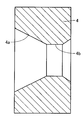
- FIG. 2 is a diagram for explaining a die shape used for drawing a pipe material.
- the drawing die 4 has a bearing portion 4b on the outlet side for determining the outer diameter of the raw pipe and an approach portion 4a whose inner diameter increases toward the inlet side for guiding the raw pipe to the bearing portion 4b. Have.
- the approach portion 4a is formed in a straight line and has a predetermined die surface angle ⁇ .
- the die surface angle ⁇ is larger than the taper angle ⁇ of the taper plug shown in FIG.
- Japanese Patent Application Laid-Open No. 2003-112218 proposes a floating plug in which a tapered portion and a straight portion (referred to as a finish portion in the same document) are connected via a recess, and is used for a fuel injection pipe of a diesel engine or the like. It is said that it is suitable for the drawing process of the thick-walled thin diameter pipe
- the floating plug proposed in Japanese Patent Application Laid-Open No. 09-225522 is provided between the tapered portion and the straight portion in order to maintain a balance between the force acting on the plug in the pulling direction and the force acting in the direction opposite to the pulling direction. Although a constricted part is provided, prevention of chatter defects and plug breakage that are likely to occur when a thick-walled tube is drawn has not been studied.
- the floating plug described in Japanese Patent Application Laid-Open No. 2003-112218 is provided with a tapered portion and a straight portion in order to remove the bite and the like generated during the internal cutting and to make the inner peripheral surface of the pipe after the drawing process highly smooth.
- chatter defects and plug breakage that are likely to occur when a thick-walled blank tube is drawn has not been studied.
- An object of the present invention is to provide a pipe drawing plug for pipe material that effectively prevents a drop and has excellent drawing performance, and a drawing method using the same.
- the present inventor observed deformation behavior of the pipe material to be processed in the drawing using various drawing plugs.
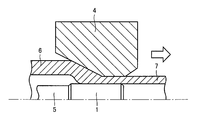
- FIG. 3 is a diagram for explaining a deformation behavior when a thick-walled raw tube is drawn using a cylindrical plug.
- the contact area between the cylindrical plug 1 and the inner surface of the blank 6 increases, so that the cylindrical plug 1 is easily drawn in the drawing direction.
- Attracting self-excited vibration that repeats the pulling and recovery of the lead, will cause chatter defects.
- chatter defects occur, minute traces are generated in the axial direction on the inner surface of the processed tube 7.
- FIG. 4 is a diagram for explaining an example of deformation behavior when a thick-walled raw tube is drawn using an SF plug.
- the SF plug 2 is inserted into the inner surface of the raw tube 6 so that the straight portion 2 s is positioned concentrically with the bearing portion 4 b of the die 4.
- the raw tube 6 is deformed along the shapes of the approach portion 4a of the die 4 and the tapered portion 2t of the SF plug 2, and the bearing portion 4b of the die 4 and the straight portion 4b of the SF plug 2
- the processed tube 7 is obtained by reducing the diameter and reducing the thickness.
- the raw tube 6 is restrained by the approach portion 4a of the die 4 and undergoes a thickening deformation while being reduced in diameter along the tapered shape.
- the thickening deformation of the raw tube becomes remarkable, and the inner surface of the raw tube 6 exceeds the distance between the approach portion 4a of the die 4 and the tapered portion 2t of the SF plug 2.
- the plug is damaged as the drawing process proceeds.
- the contact area between the processed surface of the SF plug 2 and the raw tube 6 increases, so that the force acting on the SF plug 2 increases.
- the SF plug 2 may be disengaged in the direction opposite to the pulling direction and may not float or may deviate from the proper position. In order to prevent such a situation, it is necessary to make the axial lengths of the straight portion 2s and the tapered portion 2t of the SF plug 2 appropriate.
- the present invention has been completed based on the above-described knowledge, and has the following (1) and (2) drawing plugs and (3) drawing method.
- a pipe drawing plug characterized in that a taper angle ⁇ 2 is formed and the taper angles ⁇ 1 and ⁇ 2 satisfy the relationship of the following expression (1). ⁇ 1> ⁇ 2> 0 (zero) (1)
- the taper angle ⁇ 1 of the first taper portion is 10 to 18 degrees
- the axial length L1 of the first taper portion and the second taper portion When the axial length is L2, each relationship satisfies the following expressions (2) and (3).
- the pipe material is reduced in diameter and reduced in thickness using a die having a predetermined bearing portion inner diameter and the drawing plug according to either (1) or (2) above. This is a method of drawing a pipe material.
- the plug for drawing according to the present invention is optimal when the pipe material is thick, but the ratio of the thickness T to the outer diameter D (T / D) is 20% or more. That means.
- the pipe drawing plug of the present invention it is possible to effectively prevent the occurrence of plug breakage, chatter defects, and a decrease in dimensional accuracy even when cold drawing is performed using a thick-walled pipe.
- the tool life can be extended.
- the drawing method using the plug is excellent in drawing performance, reduces product defects caused by the plug, and improves the product yield of the processed tube.
- FIG. 1 is a diagram for explaining two types of drawing processes in which different plugs are used.
- A shows a drawing process using a cylindrical plug 1 having a cylindrical surface shape with a constant outer diameter
- the drawing process using the taper plug 2 is shown.
- FIG. 2 is a diagram for explaining a die shape used for pipe drawing.
- FIG. 3 is a diagram for explaining the deformation behavior when a thick-walled raw tube is drawn using a cylindrical plug.
- FIG. 4 is a diagram for explaining an example of deformation behavior when a thick-walled raw tube is drawn using an SF plug.
- FIG. 5 is a diagram for explaining the shape of the drawing plug of the present invention and the deformation behavior in the case of drawing using the same.
- the plug for pipe drawing of the present invention has an outer surface that is formed continuously from a straight portion, a first tapered portion, and a second tapered portion in order from the tip of the plug, and the outer surface of the straight portion is cylindrical.
- the first taper portion is provided with a taper angle ⁇ 1 such that the diameter thereof increases from the straight portion toward the second taper portion, and the diameter of the second taper portion is rearward from the second taper portion.
- the taper angle ⁇ 2 is formed so as to increase toward the end, and the taper angles ⁇ 1 and ⁇ 2 satisfy the relationship of ⁇ 1> ⁇ 2> 0 (zero).
- FIG. 5 is a diagram for explaining the shape of the drawing plug of the present invention and the deformation behavior in the case of drawing using the drawing plug.
- FIG. 4 in the case of drawing a thick-walled tube using an SF plug, at the initial stage of the drawing, the tube is reduced in diameter at the approach portion of the die so as to be increased in thickness. The inner surface of the thickened pipe comes into contact with the rear end of the taper portion of the plug.
- the drawing plug 3 of the present invention is tapered from the cylindrical straight portion 3s in the direction opposite to the drawing direction.
- a conical surface-shaped first taper portion 3t1 having an angle ⁇ 1 and a conical surface-shaped second taper portion 3t2 having a taper angle ⁇ 2 are provided in series.
- the inner surface of the raw tube 6 is a taper of the plug. It is possible to prevent the portion 3t from coming out of contact with each other and to allow the contacted inner surface of the pipe to escape along the shape of the tapered portion 3t.
- drawing plug of the present invention may be simply referred to as “two-stage taper plug” as necessary.
- the raw tube 6 is reduced in diameter by the approach portion 4a of the die 4 and deformed to increase the thickness at the initial stage of the drawing process, The inner surface comes into contact with either the first taper portion 3t1 or the second taper portion 3t2 of the two-stage taper plug 3. Also in the subsequent drawing process, the raw tube 6 is deformed along the shapes of the approach portion 4a of the die 4 and the tapered portion 3t of the two-step tapered plug 3, and the die bearing portion 4b of the die 4 and the two-step tapered plug 3 are deformed. Guided between the straight portions 3s and reduced in diameter and reduced in thickness.
- a first taper portion 3t1 having a taper angle ⁇ 1 and a second taper portion 3t2 having a taper angle ⁇ 2 are continuously provided from the straight portion 3s, and the raw tube 6 is deformed thickly. However, the inner surface of the raw tube 6 is in contact with either the first taper portion 3t1 or the second taper portion 3t2.
- the inner surface of the raw tube contacts the first taper portion 3t1 or the second taper portion 3t2.
- the contact portion can escape along the shape of the tapered portion 3t of the two-stage tapered plug 3, and the deformation of the raw tube 6 can be continued.
- the taper angle ⁇ 1 of the first taper portion is 10 to 18 deg in order to ensure a floating state in the drawing process. Since the first taper portion receives a push-back force in the direction opposite to the pull-out direction that essentially acts on the plug, if the taper angle ⁇ 1 is less than 10 deg, the push-out force acting in the direction opposite to the pull-out direction necessary for floating is not present. Since it cannot be obtained sufficiently, the plug is easily pulled in and cannot be kept floating. On the other hand, when the taper angle ⁇ 1 exceeds 18 deg, the inner surface of the blank tube comes into contact with the rear end of the taper portion, and the plug is damaged.
- the axial length L1 of the first taper portion is 5 mm or more. This is to ensure a floating state in the process of drawing, and if the axial length L1 is less than 5 mm, the push-back force acting in the direction opposite to the drawing direction necessary for floating cannot be obtained. It becomes easy to be pulled in.
- the total length of the axial length L1 of the first tapered portion and the axial length L2 of the second tapered portion is 20 mm or less. This is in order to prevent the plug from being damaged, and if the total length of the axial lengths L1 and L2 of the taper portion of the plug exceeds 20 mm, the plug is likely to be damaged during the drawing process.
- the drawing method of the present invention is a method of reducing the diameter and reducing the thickness of a pipe to be processed using a die having a predetermined bearing portion inner diameter and the above-described drawing plug. Even when drawing with thick wall tubing, it is possible to effectively prevent plug breakage and chatter defects, extend tool life, and eliminate product defects caused by plugs. This can reduce the product yield.
- the effect of the present invention will be specifically described based on examples.
- the cross-sectional reduction rate Rd (%) shown in Table 1 is calculated by the following equation (4).
- Rd ⁇ (D 0 -D 1 ) / D 0 ⁇ ⁇ 100 (%) (4)
- D 0 Cross-sectional area before processing (mm 2 )
- D 1 Cross-sectional area after processing (mm 2 )
- the plugs used for the drawing were the cylindrical plug shown in FIG. 3, the SF plug shown in FIG. 4, and the two-stage taper plug shown in FIG.
- the die used at the same time had a taper surface angle ⁇ of the approach portion of 20 deg.
- Table 2 shows the dimensions of the plugs used and the evaluation results during the drawing process.
- test No In the drawing process using SF plug, test No. When a normal T / D blank tube was used as in No. 4, the drawing process could be performed. When a thick-walled tube was formed as in 5 and 6, the plug was damaged and could not be drawn.
- test No. in all of 7 to 13 a stable drawing process could be performed.
- test Nos. L1 and L2 fall within the desired range. In the case of 9, 12, and 13, excellent processing characteristics could be exhibited.
- the pipe drawing plug of the present invention it is possible to effectively prevent the occurrence of plug breakage, chatter defects, and a decrease in dimensional accuracy even when cold drawing is performed using a thick-walled pipe.
- the tool life can be extended.
- the drawing method using the plug is excellent in drawing performance, reduces product defects caused by the plug, and improves the product yield of the machined tube, and thus can be widely applied as a manufacturing method of carbon steel pipes for machine structures. .
Landscapes
- Engineering & Computer Science (AREA)
- Mechanical Engineering (AREA)
- Metal Extraction Processes (AREA)
Abstract
Priority Applications (1)
| Application Number | Priority Date | Filing Date | Title |
|---|---|---|---|
| CN200880124917.5A CN101909776B (zh) | 2008-02-08 | 2008-11-10 | 管材的拉拔加工用顶头及使用该顶头的拉拔加工方法 |
Applications Claiming Priority (2)
| Application Number | Priority Date | Filing Date | Title |
|---|---|---|---|
| JP2008029594A JP4259603B1 (ja) | 2008-02-08 | 2008-02-08 | 管材の引抜加工用プラグおよびそれを用いた引抜加工方法 |
| JP2008-029594 | 2008-02-08 |
Publications (1)
| Publication Number | Publication Date |
|---|---|
| WO2009098808A1 true WO2009098808A1 (fr) | 2009-08-13 |
Family
ID=40666674
Family Applications (1)
| Application Number | Title | Priority Date | Filing Date |
|---|---|---|---|
| PCT/JP2008/070400 Ceased WO2009098808A1 (fr) | 2008-02-08 | 2008-11-10 | Mandrin d'étirage d'un matériau de tuyau et procédé d'étirage qui l'utilise |
Country Status (5)
| Country | Link |
|---|---|
| JP (1) | JP4259603B1 (fr) |
| KR (1) | KR101175461B1 (fr) |
| CN (1) | CN101909776B (fr) |
| TW (1) | TW200934595A (fr) |
| WO (1) | WO2009098808A1 (fr) |
Cited By (2)
| Publication number | Priority date | Publication date | Assignee | Title |
|---|---|---|---|---|
| CN102423770A (zh) * | 2011-11-22 | 2012-04-25 | 西北工业大学 | 一种管材拉拔成形方法及成形模具 |
| CN115318858A (zh) * | 2022-08-18 | 2022-11-11 | 西北工业大学 | 一种低屈强比钛合金细径厚壁管及其制备方法 |
Families Citing this family (10)
| Publication number | Priority date | Publication date | Assignee | Title |
|---|---|---|---|---|
| CN102120227A (zh) * | 2011-02-22 | 2011-07-13 | 浙江健力股份有限公司 | 一种无缝钢管冷拔模具改进及其冷拔工艺 |
| CN102284532A (zh) * | 2011-08-13 | 2011-12-21 | 胡顺珍 | 新型浮动芯棒 |
| CN102632094B (zh) * | 2012-04-24 | 2014-03-12 | 西北有色金属研究院 | 一种提高钛及钛合金管材表面质量的方法 |
| KR101790100B1 (ko) * | 2015-08-05 | 2017-10-25 | 홍성박 | 중량저감형 고강도 무계목 강관 성형용 다중관 제조방법 |
| CN105945085A (zh) * | 2016-06-28 | 2016-09-21 | 上海飞轮有色新材料股份有限公司 | 用于矩形不等壁厚空心铜导线盘管的游动芯头 |
| CN106216402B (zh) * | 2016-07-28 | 2018-04-20 | 张家港华裕有色金属材料有限公司 | 钛或钛合金管冷轧增壁成型装置及方法 |
| CN106269977A (zh) * | 2016-08-07 | 2017-01-04 | 嘉兴市杰希希管道工程有限公司 | 一种小口径不锈钢管拉拔生产工艺 |
| CN107891068B (zh) * | 2017-12-19 | 2023-11-24 | 王家聪 | 改善钢管内孔螺旋缺陷的冷拔模具 |
| CN114309103A (zh) * | 2020-10-12 | 2022-04-12 | 榆林市大德机械股份有限公司 | 一种自定心冷拔模具座 |
| KR102920113B1 (ko) | 2023-12-11 | 2026-02-04 | 건우초경주식회사 | 인발용 플러그 조립체 및 이를 갖는 인발 성형 장치 |
Citations (4)
| Publication number | Priority date | Publication date | Assignee | Title |
|---|---|---|---|---|
| JPS6027414A (ja) * | 1983-07-26 | 1985-02-12 | Sumitomo Metal Ind Ltd | 曲げ管用素管の製造方法 |
| JPS6172311U (fr) * | 1984-10-18 | 1986-05-16 | ||
| JPS6292009U (fr) * | 1985-11-27 | 1987-06-12 | ||
| JPH11300411A (ja) * | 1994-04-14 | 1999-11-02 | Sumitomo Metal Ind Ltd | Baタイプクリーンパイプおよびその製造方法 |
Family Cites Families (3)
| Publication number | Priority date | Publication date | Assignee | Title |
|---|---|---|---|---|
| JPS6172311A (ja) | 1984-09-17 | 1986-04-14 | Hitachi Kiden Kogyo Ltd | 無人搬送車の誘導用光反射テ−プの読み取り装置 |
| JPS6292009A (ja) | 1985-10-17 | 1987-04-27 | Iseki & Co Ltd | 移動農作業機の音声制御装置 |
| JP2003112218A (ja) | 2001-09-28 | 2003-04-15 | Usui Internatl Ind Co Ltd | 厚肉細径管の製造方法 |
-
2008
- 2008-02-08 JP JP2008029594A patent/JP4259603B1/ja active Active
- 2008-11-10 CN CN200880124917.5A patent/CN101909776B/zh active Active
- 2008-11-10 KR KR1020107015501A patent/KR101175461B1/ko active Active
- 2008-11-10 WO PCT/JP2008/070400 patent/WO2009098808A1/fr not_active Ceased
- 2008-12-04 TW TW97147120A patent/TW200934595A/zh unknown
Patent Citations (4)
| Publication number | Priority date | Publication date | Assignee | Title |
|---|---|---|---|---|
| JPS6027414A (ja) * | 1983-07-26 | 1985-02-12 | Sumitomo Metal Ind Ltd | 曲げ管用素管の製造方法 |
| JPS6172311U (fr) * | 1984-10-18 | 1986-05-16 | ||
| JPS6292009U (fr) * | 1985-11-27 | 1987-06-12 | ||
| JPH11300411A (ja) * | 1994-04-14 | 1999-11-02 | Sumitomo Metal Ind Ltd | Baタイプクリーンパイプおよびその製造方法 |
Cited By (3)
| Publication number | Priority date | Publication date | Assignee | Title |
|---|---|---|---|---|
| CN102423770A (zh) * | 2011-11-22 | 2012-04-25 | 西北工业大学 | 一种管材拉拔成形方法及成形模具 |
| CN102423770B (zh) * | 2011-11-22 | 2013-07-17 | 西北工业大学 | 一种管材拉拔成形方法及成形模具 |
| CN115318858A (zh) * | 2022-08-18 | 2022-11-11 | 西北工业大学 | 一种低屈强比钛合金细径厚壁管及其制备方法 |
Also Published As
| Publication number | Publication date |
|---|---|
| JP4259603B1 (ja) | 2009-04-30 |
| JP2009184006A (ja) | 2009-08-20 |
| TW200934595A (en) | 2009-08-16 |
| KR20100092968A (ko) | 2010-08-23 |
| CN101909776A (zh) | 2010-12-08 |
| CN101909776B (zh) | 2013-01-02 |
| TWI339599B (fr) | 2011-04-01 |
| KR101175461B1 (ko) | 2012-08-20 |
Similar Documents
| Publication | Publication Date | Title |
|---|---|---|
| JP4259603B1 (ja) | 管材の引抜加工用プラグおよびそれを用いた引抜加工方法 | |
| CN113649427B (zh) | 一种6061铝合金薄壁管成型工艺 | |
| JP5086938B2 (ja) | 管状ワーク用引抜加工装置 | |
| JPH11300411A (ja) | Baタイプクリーンパイプおよびその製造方法 | |
| CN102227270A (zh) | 热穿孔用上表面玻璃成形材料及热挤压制管用坯材的制造方法 | |
| WO2011093055A1 (fr) | Procédé de fabrication pour tuyau de petit diamètre à paroi mince | |
| JP2006181611A (ja) | 表面品質の良好な高寸法精度管の高能率製造方法 | |
| JP5191838B2 (ja) | 管状ワークの引抜加工方法 | |
| JP2005103603A (ja) | 内面溝付管の製造装置及び内面溝付管の製造方法 | |
| JP3085980B2 (ja) | 光輝焼鈍仕上型内面高平滑ステンレス鋼管およびその製造方法 | |
| JP5149836B2 (ja) | 管状ワーク用引抜加工装置 | |
| JPH0866715A (ja) | 高平滑な外表面を有する線・棒材の製造方法 | |
| JP5448909B2 (ja) | 管状ワーク用引抜加工装置 | |
| RU2388579C2 (ru) | Многолезвийный режущий инструмент для вытяжного растачивания внутреннего отверстия заготовки под прокат | |
| CN112547822A (zh) | 一种铝合金管材拉拔成型的内芯 | |
| JP5566600B2 (ja) | メタルoリング | |
| JPH0760335A (ja) | 鋼管の引抜加工方法 | |
| JP2005066617A (ja) | 外面螺旋フィン付き金属管の製造方法および外面螺旋フィン付き金属管 | |
| JPWO1995028239A1 (ja) | 光輝焼鈍仕上型内面高平滑ステンレス鋼管およびその製造方法 | |
| JP2012086264A (ja) | 転造用平ダイス | |
| JP2007000907A (ja) | 高寸法精度管の高能率安定製造方法 | |
| JP4370853B2 (ja) | 熱間押出製管用ビレットの熱間穿孔方法 | |
| JP2005205557A (ja) | タップ | |
| JP2006346690A (ja) | 高寸法精度管の高能率安定製造方法 | |
| JP2007054882A (ja) | 高寸法精度管の高能率製造方法 |
Legal Events
| Date | Code | Title | Description |
|---|---|---|---|
| WWE | Wipo information: entry into national phase |
Ref document number: 200880124917.5 Country of ref document: CN |
|
| 121 | Ep: the epo has been informed by wipo that ep was designated in this application |
Ref document number: 08872154 Country of ref document: EP Kind code of ref document: A1 |
|
| ENP | Entry into the national phase |
Ref document number: 20107015501 Country of ref document: KR Kind code of ref document: A |
|
| NENP | Non-entry into the national phase |
Ref country code: DE |
|
| 122 | Ep: pct application non-entry in european phase |
Ref document number: 08872154 Country of ref document: EP Kind code of ref document: A1 |