WO2009104398A1 - 吐出量補正方法および塗布装置 - Google Patents
吐出量補正方法および塗布装置 Download PDFInfo
- Publication number
- WO2009104398A1 WO2009104398A1 PCT/JP2009/000694 JP2009000694W WO2009104398A1 WO 2009104398 A1 WO2009104398 A1 WO 2009104398A1 JP 2009000694 W JP2009000694 W JP 2009000694W WO 2009104398 A1 WO2009104398 A1 WO 2009104398A1
- Authority
- WO
- WIPO (PCT)
- Prior art keywords
- droplet
- mirror
- volume
- coated
- image
- Prior art date
- Legal status (The legal status is an assumption and is not a legal conclusion. Google has not performed a legal analysis and makes no representation as to the accuracy of the status listed.)
- Ceased
Links
Images





Classifications
-
- B—PERFORMING OPERATIONS; TRANSPORTING
- B05—SPRAYING OR ATOMISING IN GENERAL; APPLYING FLUENT MATERIALS TO SURFACES, IN GENERAL
- B05C—APPARATUS FOR APPLYING FLUENT MATERIALS TO SURFACES, IN GENERAL
- B05C11/00—Component parts, details or accessories not specifically provided for in groups B05C1/00 - B05C9/00
- B05C11/10—Storage, supply or control of liquid or other fluent material; Recovery of excess liquid or other fluent material
- B05C11/1002—Means for controlling supply, i.e. flow or pressure, of liquid or other fluent material to the applying apparatus, e.g. valves
- B05C11/1005—Means for controlling supply, i.e. flow or pressure, of liquid or other fluent material to the applying apparatus, e.g. valves responsive to condition of liquid or other fluent material already applied to the surface, e.g. coating thickness, weight or pattern
-
- H—ELECTRICITY
- H05—ELECTRIC TECHNIQUES NOT OTHERWISE PROVIDED FOR
- H05K—PRINTED CIRCUITS; CASINGS OR CONSTRUCTIONAL DETAILS OF ELECTRIC APPARATUS; MANUFACTURE OF ASSEMBLAGES OF ELECTRICAL COMPONENTS
- H05K3/00—Apparatus or processes for manufacturing printed circuits
- H05K3/30—Assembling printed circuits with electric components, e.g. with resistors
- H05K3/32—Assembling printed circuits with electric components, e.g. with resistors electrically connecting electric components or wires to printed circuits
- H05K3/34—Assembling printed circuits with electric components, e.g. with resistors electrically connecting electric components or wires to printed circuits by soldering
- H05K3/3465—Application of solder
- H05K3/3485—Application of solder paste, slurry or powder
-
- H—ELECTRICITY
- H10—SEMICONDUCTOR DEVICES; ELECTRIC SOLID-STATE DEVICES NOT OTHERWISE PROVIDED FOR
- H10P—GENERIC PROCESSES OR APPARATUS FOR THE MANUFACTURE OR TREATMENT OF DEVICES COVERED BY CLASS H10
- H10P72/00—Handling or holding of wafers, substrates or devices during manufacture or treatment thereof
- H10P72/04—Apparatus for manufacture or treatment
- H10P72/0402—Apparatus for fluid treatment
-
- B—PERFORMING OPERATIONS; TRANSPORTING
- B05—SPRAYING OR ATOMISING IN GENERAL; APPLYING FLUENT MATERIALS TO SURFACES, IN GENERAL
- B05C—APPARATUS FOR APPLYING FLUENT MATERIALS TO SURFACES, IN GENERAL
- B05C11/00—Component parts, details or accessories not specifically provided for in groups B05C1/00 - B05C9/00
- B05C11/10—Storage, supply or control of liquid or other fluent material; Recovery of excess liquid or other fluent material
-
- H—ELECTRICITY
- H05—ELECTRIC TECHNIQUES NOT OTHERWISE PROVIDED FOR
- H05K—PRINTED CIRCUITS; CASINGS OR CONSTRUCTIONAL DETAILS OF ELECTRIC APPARATUS; MANUFACTURE OF ASSEMBLAGES OF ELECTRICAL COMPONENTS
- H05K1/00—Printed circuits
- H05K1/02—Details
- H05K1/0266—Marks, test patterns or identification means
- H05K1/0269—Marks, test patterns or identification means for visual or optical inspection
-
- H—ELECTRICITY
- H10—SEMICONDUCTOR DEVICES; ELECTRIC SOLID-STATE DEVICES NOT OTHERWISE PROVIDED FOR
- H10P—GENERIC PROCESSES OR APPARATUS FOR THE MANUFACTURE OR TREATMENT OF DEVICES COVERED BY CLASS H10
- H10P72/00—Handling or holding of wafers, substrates or devices during manufacture or treatment thereof
- H10P72/04—Apparatus for manufacture or treatment
- H10P72/0448—Apparatus for applying a liquid, a resin, an ink or the like
Definitions
- the present invention relates to a method and a coating apparatus for correcting a change in discharge amount accompanying a change in viscosity of a liquid material over time, and more specifically, for example, by measuring the amount of droplets applied to a substrate,
- the present invention relates to a method for correcting an ejection amount based on a measured value and a coating apparatus.
- Patent Document 1 As a technique for measuring the amount of discharged liquid material using a dedicated measuring device and adjusting the discharge amount based on the result, the liquid material using an electronic balance, for example, for variations in the discharge amount of the liquid material
- Patent Document 2 There is a discharge amount correction method (Patent Document 1) for measuring the weight of the liquid and an apparatus for measuring the droplet amount based on an image obtained by imaging the droplet (Patent Document 2).
- Patent Document 1 when the weight of the material discharged periodically is measured and the measured weight is compared with the designated weight, the measured weight is corrected by correcting the number of pulses and the pulse frequency for driving the pulse motor pump.
- a discharge amount correction method for performing control to approach a specified weight is disclosed.
- a step of registering a target application amount, a step of applying a gas pressure to a syringe and ejecting a bond from a nozzle to perform trial application, a test-applied bond is recognized, and the size of the application amount is calculated.
- a coating amount adjusting method for repeating the above steps is disclosed.
- JP 2002-303275 A Japanese Patent Laid-Open No. 11-97829
- An object of the present invention is to provide a discharge amount correction method and a coating apparatus capable of accurately measuring the amount of applied droplets and correcting the discharge amount with high accuracy.
- a first invention is a discharge amount correction method for measuring the amount of liquid material discharged from a nozzle and correcting the discharge amount.
- a mirror is installed at a predetermined angle with the surface to be coated in the vicinity of the surface to be coated. Discharge characterized in that the droplet formed on the coating surface is imaged from the side through a mirror, the volume of the droplet is calculated based on the image of the captured droplet, and the discharge amount is corrected based on the calculated volume This is an amount correction method.
- the mirror is a plurality of mirrors arranged orthogonally or symmetrically, and images a droplet a plurality of times from different angles in the horizontal direction.
- the volume of the droplet is calculated based on the image of the droplet.
- the liquid droplets or the mirror formed on the surface to be coated are rotated, and the liquid droplets are imaged a plurality of times from different angles in the horizontal direction. It is characterized in that the volume of the droplet is calculated based on the image of the droplet.
- the volume of the droplet is calculated based on an area of a silhouette on a side of the droplet.
- the volume of the droplet is calculated based on a height and a width of a silhouette on a side of the droplet.
- an image of a plane silhouette of a droplet is imaged, and when the roundness of the plane silhouette exceeds an allowable range, the droplet is re-formed on the surface to be coated. It is characterized by that.
- the surface to be coated before forming droplets on the surface to be coated is imaged from the side via a mirror, and the captured image of the surface to be coated is obtained.
- the boundary line of the surface to be coated is stored based on the image, and the volume of the droplet is calculated for a region above the boundary line in the captured droplet image.
- the predetermined angle is 45 degrees.
- a storage container for storing a liquid material
- a discharge device having a nozzle for discharging the liquid material
- an image pickup device for picking up liquid droplets applied to a surface to be coated
- a cover near the surface to be coated.
- a liquid material applicator comprising a mirror installed at a predetermined angle with respect to the application surface, and a controller, wherein the imaging device and the mirror can image liquid droplets formed on the application surface from the side.
- the liquid material applicator is arranged at various positions.
- a light source is provided to face the mirror.
- An eleventh aspect of the invention is the ninth or tenth aspect of the invention, wherein the mirror is a plurality of mirrors arranged orthogonally or symmetrically, and the image pickup device drops liquid droplets in the horizontal direction via the mirror. It is located so that it can image from an angle.
- a twelfth invention is characterized in that in any one of the ninth to eleventh inventions, a stage for rotating the droplet formed on the coated surface is provided.
- a thirteenth invention is characterized in that, in any one of the ninth to eleventh inventions, a mirror that rotates with respect to the droplet formed on the coated surface is provided.
- a fourteenth aspect of the invention is characterized in that, in the ninth or tenth aspect of the invention, a transport mechanism that allows the substrate to move in one direction is provided, and the mirror is installed in the vicinity of the transport mechanism.
- a fifteenth invention is characterized in that, in any one of the ninth to fourteenth inventions, the predetermined angle is 45 degrees.
- the present invention since the amount of droplets can be measured accurately, the ejection amount can be corrected with high accuracy. Further, the present invention can easily measure the amount of droplets in principle.
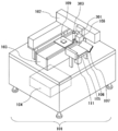
- FIG. 1 is a schematic perspective view of a coating apparatus according to Example 1.
- FIG. It is explanatory drawing explaining the installation aspect of the mirror which concerns on Example 1.
- FIG. 1 is a cross-sectional view of a main part of a discharge device according to Embodiment 1.
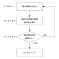
- FIG. 3 is a flowchart illustrating a correction procedure according to the first embodiment.
- 10 is a flowchart illustrating a modification of the correction procedure according to the first embodiment. It is explanatory drawing explaining the volume calculation method which concerns on Example 1.
- FIG. It is explanatory drawing explaining the volume calculation method which concerns on Example 1.
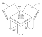
- FIG. 10 is an explanatory diagram for explaining an installation example of a mirror according to Embodiment 2.
- FIG. 10 is an explanatory diagram for explaining an installation example of a mirror according to a third embodiment.
- 10 is an explanatory diagram for explaining an installation example of a mirror according to Embodiment 4.
- FIG. 10 is an explanatory diagram illustrating an imaging method according to a fifth embodiment.
- the “relationship between the discharge pressure and the discharge volume” when the initially set discharge time is fixed is obtained in advance by a test or the like, and stored in the control unit 104 in the data format of an equation or a correspondence table. Based on the “relationship between the discharge pressure and the discharge volume”, the discharge pressure P is set as a control parameter required for discharging the target volume. These data stored in the control unit 104 are used as control data when calculating the correction amount. Moreover, it is preferable to store the value calculated based on the pot life specified by the manufacturer as the limit value of the usage time of the liquid material in association with each of the above data.
- a correction cycle that is a cycle for correcting the discharge amount is set.
- the correction cycle for example, time information input by the user, the number of substrates 109 to be processed, and the like are set.
- the correction cycle is set by time, the time when the change in the discharge amount of the liquid material is expected to exceed the allowable range from the start of work is set.
- the number of sheets is set, the number of sheets to be processed is determined and set based on the time for processing one substrate 109 (loading ⁇ application ⁇ unloading time) and the predetermined time.
- the imaging device 108 is moved above the mirror 107 placed near the substrate (106 or 109) at an angle with respect to the coated surface of the substrate, and the droplet 201 from a direction parallel to the coated surface is moved. Image the shape.
- a projection surface geometric amount in the horizontal direction is calculated based on the captured image data, and the measurement volume V of the ejected liquid droplets is calculated based on the projection surface geometric amount in the horizontal direction. 1 is calculated.
- the correction of the discharge amount is not always performed when the volume difference (V 1 ⁇ V 0 ) or the change rate R is not zero, but the calculated volume difference or change rate R is within an allowable range (for example, ⁇ 5%). It is preferable to carry out only when exceeding.
- a preferred mode of correction with an allowable range is detailed in, for example, Japanese Patent No. 3877038 relating to the applicant's patent application. That is, an allowable range for determining whether to perform correction is provided, and the discharge pressure is corrected only when the difference value or rate of change R exceeds the allowable range.
- the discharge device in the present invention is not limited to the jet type discharge device described above, and can be implemented in various discharge devices that discharge a liquid material.
- the control parameter to be adjusted is not limited to the discharge pressure, and includes, for example, the following.
- the jet type discharge device the time during which the piston is rising and the time during which the piston is falling may be adjusted.
- a screw-type discharge device that discharges a liquid material by rotating a screw, the number of rotations of the screw may be adjusted.
- the plunger-type discharge device that moves and discharges a plunger that slides in close contact with the inner surface of a storage container having a nozzle at the tip, the movement amount of the plunger may be adjusted.
- the coating apparatus 101 includes an ejection device 301, an imaging device 108, an XYZ drive mechanism 102, a transport mechanism 103, and an adjustment mechanism 401 positioned in the vicinity of the transport mechanism 103. And a control unit 104 for controlling these operations.
- the discharge device 301 has a storage container 303 for storing the liquid material and a nozzle 304 for discharging the liquid material.
- the discharge device 301 is attached to the XYZ drive mechanism 102 and is movable onto the application target substrate 109 and the adjustment substrate 106.
- the imaging device 108 is a device for imaging the droplets ejected on the substrate.
- a CCD camera is used in consideration of performing image processing on the captured image data.
- the imaging device 108 is attached to the XYZ drive mechanism 102 so that the objective surface 110 for capturing an image faces the coated surface of the substrate (106, 109).
- the substrate 106 and the mirror 107 can be moved upward. Further, the imaging device 108 is movable in the Z direction, and thereby the focal length can be adjusted.
- the imaging device 108 is also used as a substrate position recognition camera described later. In such a configuration, installation space can be saved, and the coating apparatus 101 can be further downsized.
- the imaging device 108 When the imaging device 108 is installed in the XYZ drive mechanism 102, it may be installed integrally with the ejection device 301 as shown in FIG. 1 or may be installed independently of the ejection device 301. Good.
- the adjustment mechanism 401 includes an adjustment substrate 106, an adjustment stage 105 on which the adjustment substrate 106 is placed, a mirror 107 installed in the vicinity of the adjustment substrate 106, and a light source 111.
- the adjustment substrate 106 is a substrate for measuring the discharge amount from the nozzle 304.
- the adjustment substrate 106 is placed so as to be the same height as the application target substrate 109. This is because when the imaging device 108 is also used as a substrate position recognition camera, it is not necessary to adjust the focal length between the substrate recognition at the time of positioning and the imaging at the time of volume calculation. That is, the Z-direction position setting can be made common, and the trouble of making separate settings for the substrates 106 and 109 can be saved. As shown in FIG.
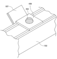
- the mirror 107 is installed near the adjustment substrate 106 at an angle ⁇ . More specifically, the mirror 107 is installed such that the surface on which the image is projected is at an angle ⁇ with respect to the application surface of the adjustment substrate 106 (the object surface 110 of the imaging device 108). Thus, by installing the mirror 107 with the angle ⁇ , the side image of the droplet 201 applied to the substrate (106, 109) can be reflected by the mirror 107 and imaged by the imaging device 108. .
- the mirror 107 is installed at a height at which the droplet 201 appears in the central portion (see FIG. 2).
- the light source 111 is a flat light (planar light source) disposed to face the mirror 107 with the adjustment substrate 106 interposed therebetween, and can be constituted by a known light source such as an LED. By irradiating light toward the mirror 107 by the light source 111, the silhouette of the droplet 201 is made clear.
- the surface on which the image of the mirror 107 is projected is the application surface of the substrate (106, 109). Is preferably set to 45 degrees.
- the horizontal image of the droplet 201 applied to the substrate (106, 109) can be reflected in the vertical direction, and the shape can be captured without distortion such as being inclined. It is.
- the side image of the liquid droplet is incident on the image pickup apparatus by a single mirror, but the side image of the liquid droplet may be transmitted to the image pickup apparatus by a plurality of mirrors.
- the substrate 109 that is the object to be applied is transferred to the lower part of the discharge device 301 by the transfer mechanism 103. After the substrate 109 is carried under the nozzle 304 and the substrate 109 is positioned, application by the discharge device 301 is started.
- the locus of the application operation of the nozzle 304, that is, the application pattern, is stored in advance in a storage device (memory or the like) in the control unit 104.
- the substrate 109 is carried out of the coating apparatus 101 to the outside by the transport mechanism 103. Subsequently, the next substrate 109 is carried in and the coating operation is repeated.
- the loading, coating, and unloading become one cycle, and the coating operation is repeated until the coating of the desired number of substrates 109 is completed.
- the ejection amount is corrected at a preset correction cycle timing. That is, the ejection amount changed due to the change in the viscosity of the liquid material is corrected.
- the correction amount is calculated by moving the nozzle 304 above the adjustment substrate 106 by the XYZ drive mechanism 102 and calculating the volume of the droplet 201 from image data obtained by imaging the droplet 201 applied on the adjustment substrate 106. To do. Details of the correction procedure will be described later.
- a discharge device 301 shown in FIG. 3 includes a piston 302 that is provided so as to be movable up and down, a storage container 303 that stores a liquid material, and a nozzle 304 that communicates with the storage container.
- the liquid material in the storage container 303 is pressurized by the regulated compressed gas supplied from the discharge control unit 305 through the compressed gas supply line 307.
- the liquid material 210 supplied from the storage container 303 to the piston chamber is discharged from the nozzle 304 in the form of droplets by reciprocating the piston 302 up and down based on a discharge signal from the discharge control unit 305.
- the droplet 201 ejected from the nozzle 304 is applied in a dot-like manner to a substrate (106, 109) positioned under the nozzle 304.
- the target volume V 0 and the measured volume V 1 are compared (STEP 13), and the presence or absence of correction is determined based on whether the volume difference exceeds the allowable range (STEP 14).
- the rate of change R is negative, the measured volume V 1 is smaller than the target volume V 0. Therefore, the control parameter in consideration of the increase in the measured volume V 1 according to the rate of change R is set in advance by the control unit.
- the discharge pressure is reset by calculating from the control data stored in 104 (STEP 17).
- the rate of change R is positive
- the discharge volume V 1 is larger than the target volume V 0 , and therefore, a setting parameter that takes into account the decrease in the discharge volume V 1 according to the rate of change R is sent to the control unit 104.
- the discharge pressure is reset by calculating from the stored control data (STEP 18).
- the determination of STEP14 is not performed, and the determination is performed between STEP13 to STEP15 and STEP16.
- a step of calculating the roundness of the projection surface shape (planar silhouette) when the droplet 201 is viewed from the vertical direction and determining whether the calculated value is within an allowable range may be added.
- STEP 23 it is determined whether or not the roundness exceeds an allowable range. If it is determined that the roundness is within the allowable range, the process proceeds to STEP 12 shown in FIG. 4 to calculate the volume of the droplet 201 and correct the ejection amount. When it is determined that the roundness is out of the allowable range, the process returns to STEP 21 and discharge is performed again. At this time, the number of times of returning to STEP 21 may be set, and an alarm may be issued as an error when the set number of times is exceeded.
- volume calculation method There are various methods for volume calculation. Here, the following two examples are shown.
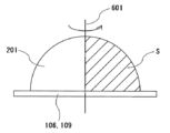
- (A) Method of calculating from the area of the horizontal projection plane shape As indicated by the hatched portion S shown in FIG. 6, the half of the horizontal projection plane shape is obtained from the image of the droplet 201 applied to the substrate (106, 109). Considering a plane (hatched portion S) having an area, the volume of the coated droplet 201 is a solid formed by rotating the plane around an axis 601 shown in FIG. That is, first, from the image of the droplet 201 applied to the substrate (106, 109), an area S (a sector area having a central angle of 90 degrees) half of the horizontal projection plane shape is obtained by image processing, and the obtained area.
- the volume is calculated by integrating S.
- Droplet 201 applied to the substrate (106, 109) is a hemisphere or a missing sphere (a part of a sphere whose height is shorter than the radius of the sphere. For example, a dome shape.)
- the volume is calculated from the geometric volume calculation formula. That is, as shown in FIG. 7, from the image of the droplet 201 applied to the substrate (106, 109), the length of the bottom of the horizontal projection plane shape is set to the diameter d, or a half value thereof is set to the radius. r is calculated, and the maximum length in the vertical direction is set as height h.
- the coating apparatus can capture the shape of the droplet 201 more accurately by acquiring an image obtained by imaging the droplet 201 from the side by the mirror 107.
- the volume can be accurately measured.
- the coating apparatus of this embodiment since the mirror 107 is used, it is not necessary to separately install an imaging apparatus for imaging the droplet 201 from the side, so that installation space can be saved and the apparatus can be downsized. is there.
- the coating apparatus according to the present embodiment is different from the coating apparatus according to the first embodiment in that the adjustment mechanism 401 includes two mirrors 107.
- the coating apparatus of the present embodiment is provided with two mirrors 107 so as to capture the shape of the droplet 201 viewed from two directions parallel to and orthogonal to the substrate coating surface. ing.
- the two mirrors 107 are installed at the same angle ⁇ as in the first embodiment.
- the two mirrors 107 are installed such that the orientation of the surface on which the image is projected is perpendicular to the adjustment substrate 106.
- two light sources 111 are also required.
- the light source 11 may be physically configured by two light sources, or may be configured to irradiate light from one light source by dividing it into two lights by an optical system.
- the imaging device 108 When imaging the droplet 201 applied on the substrate 106, first, the imaging device 108 is moved above the one mirror 107 to capture the projection plane shape (side image) from the horizontal direction of the droplet 201. To do. Next, the imaging device 108 is moved above the other mirror 107, and the shape of the projection plane from the direction orthogonal to the projection plane first imaged is captured. Then, the values (r or d) calculated from the lengths of the bases in the two captured images are compared, and when the lengths are the same, the volume is calculated as a hemisphere, and when the lengths are different, the ellipsoid The volume is calculated assuming that it is half of the volume.
- the configuration including the two mirrors 107 orthogonal to each other in the present embodiment it is possible to acquire the image of the droplet 201 captured from two directions orthogonal to each other. Thereby, since the shape of the droplet 201 can be accurately captured, the volume of the droplet 201 can be measured with higher accuracy.
- the apparatus of the present embodiment is the same as the first embodiment in that the mirror 107 installed in the vicinity of the substrate 106 at an angle with respect to the surface to be coated of the substrate and the angle ⁇ are set.
- a rotation drive mechanism 901 that rotates the adjustment stage 105 is provided.
- the adjustment stage 105 is rotated with respect to the mirror 107 by a rotation driving mechanism 901 provided below the adjustment stage 105. Since the adjustment stage 105 rotates, a horizontal image of the droplet 201 can be taken from two or more directions.
- the imaging device 108 is moved above the installed mirror 107 to image the shape of the projection surface in the horizontal direction with respect to the substrate application surface.
- the adjustment stage 105 is rotated while the position of the imaging device 108 is fixed.
- the rotation amount of the adjustment stage 105 can be arbitrarily adjusted. For example, the rotation amount is set to 90 degrees (two times of imaging) or 120 degrees (three times of imaging).
- the side image of the different position of the droplet 201 is imaged.
- the method for calculating the volume from two or more captured images is the same as in the second embodiment.
- the shape of the droplet 201 can be captured more accurately by acquiring images captured from two or more directions.
- the volume of the droplet 201 can be measured with higher accuracy.
- a light source or an optical system that allows light to enter the mirror following the rotation of the mirror is required.
- the coating apparatus of this embodiment includes a mirror 107 disposed adjacent to a transport mechanism 103 that can move a substrate 109 in one direction.
- the mirror 107 is disposed in the vicinity of the position where the coating target substrate 109 placed on the stage is positioned.
- a light source 111 (not shown) is disposed to face the mirror 107 with the stage interposed therebetween.
- the imaging of the droplet 201 applied on the substrate 106 is performed in the same procedure as in the first embodiment, and the volume calculation method of the droplet 201 is the same as in the first embodiment. In the configuration of the present embodiment, the volume is calculated by imaging the droplet 201 applied to the application target substrate 109. Therefore, the time required for application to the adjustment substrate 106 and the time required to image the adjustment substrate 106 are not required, and the time required for correction can be shortened.
- the substrate when the droplet is focused, the substrate may not be focused, and the boundary with the droplet, that is, the edge of the upper surface of the substrate may not be clearly visible. Yes (FIG. 11 (a)). That is, the boundary line may be blurred, resulting in an error during image recognition or volume calculation. In that case, the following method is performed in order to perform more precise measurement. First, as a preparation, the substrate before droplet application is photographed, and the boundary line on the upper surface of the substrate is recognized and stored (FIG. 11B). Then, when a droplet is applied on the substrate and the droplet is imaged and measured, image recognition and volume calculation are performed based on the boundary line stored as the preparation.
- the volume calculation is performed by recognizing only the image of the region above the boundary line stored as the preparation (FIG. 11C). By performing image recognition and volume calculation as described above, it is possible to more accurately measure the discharge amount of droplets. Here, it is preferable to adjust the focal point by operating the Z drive mechanism when photographing the substrate before droplet application. In addition, the image of the substrate before applying the liquid droplets basically needs to be imaged only once as long as the position of the substrate, the camera, or the like does not change.
- the present invention can be implemented in various apparatuses for discharging a liquid material.
- a discharge method of the type in which the liquid material comes into contact with the substrate before being separated from the discharge device an air type, a flat tubing mechanism or the like that applies a regulated air to the liquid material in the syringe having a nozzle at the tip for a desired time.
- Tubing type with a rotary tubing mechanism plunger type that moves a desired amount of plunger sliding closely against the inner surface of a storage container having a nozzle at the tip, a screw type that discharges liquid material by rotating the screw, desired pressure
- a valve type that controls discharge of the liquid material to which is applied by opening and closing the valve is exemplified.
- a jet type plunger that plungers and discharges the liquid material from the nozzle tip by colliding the valve body with the valve seat is used.
- Examples include a plunger jet type that is moved, then suddenly stopped, and then ejected and ejected from the tip of the nozzle, a continuous jet type, or an on-demand type ink jet type.
- the present invention can also be implemented in various coating apparatuses that apply a prescribed amount of liquid material. For example, a seal coating device, a liquid crystal dropping device, and a solder paste coating device for a printed circuit board in a liquid crystal panel manufacturing process can be used.
Landscapes
- Engineering & Computer Science (AREA)
- Microelectronics & Electronic Packaging (AREA)
- Coating Apparatus (AREA)
- Manufacturing & Machinery (AREA)
- Application Of Or Painting With Fluid Materials (AREA)
Abstract
Description
近年、チップの小型化や高密度実装化、或いは、塗布作業の多様化に伴い、微量で精密な塗布を持続的に行うことが求められており、吐出量のばらつきをより少なく抑えることが必要とされている。中でも、アンダーフィル工程においては、より微量でより精密な塗布が要求される。
特許文献1には、定期的に吐出した材料の重量を測定して実測重量と指定重量を比較して異なるときは、パルスモータポンプ駆動のためのパルス数とパルス周波数を修正して実測重量を指定重量へ近づける制御を行う吐出量補正方法が開示されている。
特許文献2には、目標塗布量を登録する工程、シリンジに気体圧を付与してノズルからボンドを吐出し試し塗布する工程、試し塗布されたボンドを認識して塗布量の大きさを算出する工程、算出した試し塗布量と目標塗布量とを比較し、その差が許容誤差以内であるかを判定する工程、許容誤差以内でないときはシリンジに付与する気体圧の大きさまたは時間を変更して上記工程を繰り返す塗布量調整方法が開示されている。
また、特許文献2に記載の発明においては、カメラで認識した液体材料の上方からのシルエットにより液滴の量を算出しているため、高さを認識できず、液滴の量を正確に算出することはできなかった。
第2の発明は、第1の発明において、前記ミラーは、直交してまたは対称に配置された複数枚のミラーであり、液滴を水平方向の異なる角度から複数回撮像し、撮像した複数の液滴の画像に基づき液滴の体積を算出することを特徴とする。
第3の発明は、第1の発明において、前記被塗布面に形成された液滴または前記ミラーを回動させて、液滴を水平方向の異なる角度から複数回撮像し、撮像した複数の液滴の画像に基づき液滴の体積を算出することを特徴とする。
第4の発明は、第1ないし3のいずれかの発明において、液滴の体積を、液滴の側方のシルエットの面積に基づき算出することを特徴とする。
第5の発明は、第1ないし3のいずれかの発明において、液滴の体積を、液滴の側方のシルエットの高さおよび幅に基づき算出することを特徴とする。
第6の発明は、第4または5の発明において、液滴の平面のシルエットを撮像し、平面のシルエットの真円度が許容範囲を超える場合には、被塗布面に液滴を再形成することを特徴とする。
第7の発明は、第1ないし6のいずれかの発明において、被塗布面に液滴を形成する前の被塗布面をミラーを介して側方より撮像し、撮像した被塗布面の画像に基づき被塗布面の境界線を記憶し、前記撮像した液滴の画像において境界線より上の領域について液滴の体積を算出することを特徴とする。
第8の発明は、第1ないし7のいずれかの発明において、前記所定の角度が45度であることを特徴とする。
第10の発明は、第9の発明において、前記ミラーと対向して設けられた光源を備えることを特徴とする。
第11の発明は、第9または10の発明において、前記ミラーは、直交してまたは対称に配置された複数枚のミラーであり、前記撮像装置は、ミラーを介して液滴を水平方向の異なる角度から撮像可能に位置されることを特徴とする。
第12の発明は、第9ないし11のいずれかの発明において、前記被塗布面に形成された液滴を回動するステージを備えることを特徴とする。
第13の発明は、第9ないし11のいずれかの発明において、前記被塗布面に形成された液滴に対し回動するミラーを備えることを特徴とする。
第14の発明は、第9または10の発明において、前記基板を一の方向に移動自在とする搬送機構を備え、前記ミラーは、搬送機構の近傍に設置されることを特徴とする。
第15の発明は、第9ないし14のいずれかの発明において、前記所定の角度が45度であることを特徴とする。
また、本発明は、原理上、液滴の量を簡易に測定することができる。
101 塗布装置\102 XYZ駆動機構\103 搬送機構\104 制御部\105 調整用ステージ\106 調整用基板\107 ミラー\108 撮像装置\109 基板\110 撮像装置の対物面\111 光源\201 液滴\301 吐出装置\302 ピストン\303 貯留容器\304 ノズル\305 吐出制御部\306 吐出信号ライン\307 圧縮気体供給ライン\401 調整機構\601 回転軸\901 回転駆動機構\S 面積\h 高さ\r 半径\d 直径\α 角度
[1]初期パラメータの設定
まず、所望とする塗布に対する目標体積V0および目標塗布長さL0を設定する。次に、一定速度で塗布を行うとして、目標塗布長さL0と所望とする塗布速度から吐出時間Tを設定する。この際、最初に設定した吐出時間を固定した場合における「吐出圧力と吐出体積との関係」を予め試験などにより求めておき、式や対応表のデータ形式で制御部104に記憶しておく。この「吐出圧力と吐出体積との関係」をもとに、目標体積を吐出するのに要する制御パラメータとして、吐出圧力Pを設定する。制御部104に記憶したこれらのデータは、制御用データとして補正量の算出時に利用される。
また、液体材料の使用時間の限界値として、メーカーの規定するポットライフに基づいて算出した値を上記の各データと関連づけて記憶しておくことが好ましい。
吐出量を補正する周期である補正周期を設定する。補正周期としては、例えば、ユーザーが入力した時間情報、処理すべき基板109の枚数などを設定する。補正周期を時間で設定する場合は、液体材料の吐出量の変化が作業開始から許容範囲を越えると予想される時間を設定する。枚数を設定する場合は、一枚の基板109を処理する時間(搬入→塗布→搬出の時間)と、上記所定の時間から処理枚数を求め、設定する。
補正周期設定の際は、時間の経過や温度の変化により生ずる液体材料の粘度変化を考慮する必要があるが、以下では時間の経過に伴う粘度変化のみが生ずることを前提に説明を行うものとする。
なお、ノズルを有する吐出部を温度調整することにより液体材料の粘度を制御する公知の技術を本発明に併用できることは言うまでもない。
設定された補正周期で、液体材料の粘度変化による吐出量の変化に対応するための補正量を算出する。
まず、ノズル304を基板(106または109)の上方へ移動させ、上記[1]で制御用データとして制御部104に記憶した、吐出圧力Pと吐出時間Tに基づき液体材料を吐出する。これにより、基板の塗布面に滴状の液滴201が形成される。続いて、基板上に塗布された液滴201の水平方向の形状を撮像し、撮像した画像データから吐出された液滴の計測体積V1を算出する。より詳しくは、基板(106または109)の近傍に基板の被塗布面に対して角度をもって設置したミラー107の上方へ撮像装置108を移動し、被塗布面に平行な方向からの液滴201の形状を撮像する。この際、ミラー107の正面には所定の面積を有する平面光源または背景となる平面部材を設置することが好ましい。そして、撮像した画像データに基づき水平方向(塗布面に平行な方向)の投影面幾何学量を算出し、当該水平方向の投影面幾何学量をもとに吐出された液滴の計測体積V1を算出する。
変化率Rがマイナスの場合、変化率Rに応じた吐出量増加が加味された吐出圧力の設定を、上記[1]で記憶した「吐出圧力と吐出体積との関係」より求める。
変化率Rがプラスの場合、変化率Rに応じた吐出量減少が加味された吐出圧力の設定を、上記[1]で記憶した「吐出圧力と吐出体積との関係」より求める。
上記[3]で吐出量の補正が必要であると判断した場合には、変化率Rに応じた吐出量の増加あるいは減少分が加味された吐出圧力の設定を、上記[1]で記憶した「吐出圧力と吐出体積との関係」より求める。そして、制御パラメータ(吐出圧力P)の設定を変更することで吐出量を補正する。
本発明における吐出装置は、上記で説明したジェット式の吐出装置に限定されるものではなく、液体材料を吐出する種々の吐出装置において実施可能である。調整する制御パラメータは、吐出圧力に限定されず、例えば、次のものがある。
ジェット式吐出装置において、ピストンが上昇している時間および下降している時間を調整してもよい。
スクリューの回転により液体材料を吐出するスクリュー式吐出装置において、スクリューの回転数を調整してもよい。
先端にノズルを有する貯留容器の内面に密着摺動するプランジャーを所望量移動して吐出するプランジャー式吐出装置において、プランジャーの移動量を調整してもよい。
本実施例に係る塗布装置101は、図1に示すように、吐出装置301と、撮像装置108と、XYZ駆動機構102と、搬送機構103と、搬送機構103の近傍に位置する調整機構401と、これらの動作を制御する制御部104とを備えている。
吐出装置301は、液体材料を貯留する貯留容器303と、液体材料を吐出するためのノズル304を有している。吐出装置301は、XYZ駆動機構102に取り付けられており、塗布対象基板109や調整用基板106の上へ移動可能である。
撮像装置108は、基板上に吐出された液滴を撮像するための装置である。本実施例では、撮像した画像データに画像処理を施すことを考慮し、CCDカメラを使用した。撮像装置108は、画像を捉える対物面110が基板(106、109)の被塗布面に対向するようXYZ駆動機構102に取り付けられており、吐出装置301と同様に、塗布対象基板109、調整用基板106、およびミラー107の上方へ移動可能である。また、撮像装置108は、Z方向へ移動自在であり、これにより焦点距離を調節することができる。
また、本実施例では、撮像装置108は、後述の基板位置認識用カメラとして兼用している。かかる構成においては、設置スペースを節約することができ、塗布装置101をより小型化することができる。
なお、撮像装置108をXYZ駆動機構102に設置する際は、図1に示すように吐出装置301の横に一体的に設置してもよいし、吐出装置301とは独立して設置してもよい。
調整機構401は、調整用基板106と、調整用基板106を載置する調整用ステージ105と、調整用基板106の近傍に設置されるミラー107と、光源111とを備えている。
調整用基板106は、ノズル304からの吐出量を計測するための基板である。調整用基板106は、塗布対象基板109と同じ高さとなるよう載置される。これは、撮像装置108を基板位置認識用カメラとして兼用する場合に、位置決め時の基板認識と体積算出時の撮像とで、焦点距離調節が不要となるからである。すなわち、Z方向位置設定を共通にすることができるのであり、基板106と109で別々の設定をする手間を省くことができる。
ミラー107は、図2に示すように、調整用基板106近傍に角度αで設置される。より具体的には、ミラー107は、その像を映す面が、調整用基板106の被塗布面(撮像装置108の対物面110)に対して角度αとなるように設置されている。このように、角度αをもってミラー107を設置することで、基板(106、109)に塗布された液滴201の側方像をミラー107で反射し、撮像装置108で撮像することが可能となる。ミラー107は、その中心部分に液滴201が写る高さに設置する(図2参照)。
光源111は、調整用基板106を挟んで、ミラー107と対向して配置されるフラットライト(平面光源)であり、LED等の公知の光源により構成することができる。光源111によりミラー107に向かって光を照射することで、液滴201のシルエットを鮮明にしている。
本実施例のように、撮像装置108の対物面110が基板(106、109)の被塗布面と対向する構成においては、ミラー107の像を映す面が基板(106、109)の被塗布面に対して構成する角度αを45度とすることが好ましい。角度αを45度とすることで、基板(106、109)に塗布された液滴201の水平方向の像を垂直方向へ反射することができ、斜めになるなどの歪みなく形状を撮像できるからである。
なお、本実施例では、1枚のミラーにより撮像装置に液滴の側方像を入射しているが、複数のミラーにより液滴の側方像を撮像装置に伝送する構成としてもよい。
塗布が終了すると、基板109は搬送機構103によって塗布装置101から外部へ搬出される。続いて、次の基板109が搬入され、塗布作業が繰り返される。このように、搬入、塗布および搬出が一つのサイクルとなり、所望の枚数の基板109への塗布が終了するまで、塗布作業が繰り返される。
上記サイクルの途中、予め設定した補正周期のタイミングで、吐出量の補正が行われる。すなわち、液体材料の粘度変化により変化した吐出量の補正が行われる。補正量の算出は、XYZ駆動機構102によりノズル304を調整用基板106の上方へ移動し、調整用基板106の上に塗布された液滴201を撮像した画像データから液滴201の体積を算出することにより行う。補正手順の詳細については後述する。
吐出装置301には種々の装置が利用可能であるが、本実施例では、図3に示すようなジェット式吐出装置を使用した。
図3に示す吐出装置301は、上下動自在に内設されたピストン302と、液体材料を貯留する貯留容器303と、貯留容器と連通するノズル304とを備えている。
貯留容器303内の液体材料は、吐出制御部305から圧縮気体供給ライン307を通して供給される調圧された圧縮気体により加圧されている。貯留容器303からピストン室に供給された液体材料210は、吐出制御部305からの吐出信号に基づき、ピストン302を上下に往復動作することにより、ノズル304から液滴状に吐出される。ノズル304から吐出された液滴201は、ノズル304の下に位置決めされた基板(106、109)に点状に塗布される。
本実施例における補正手順1を、図4のフローチャートを参照しながら説明する。
まず、吐出圧力と吐出体積との関係から求まる目標体積を吐出するための適正吐出時間を算出し、適正吐出時間の間、基板上に液体材料を吐出する(STEP11)。次に、液滴201を水平方向から見た形状(基板の被塗布面に対して平行方向から見た形状)を、基板の被塗布面に対して角度αで設置されたミラー107を介して撮像し、その画像に基づき液滴201の計測体積V1を算出する(STEP12)。続いて、目標体積V0と計測体積V1とを比較し(STEP13)、体積差が許容範囲を越えるか否かにより補正の有無を判定する(STEP14)。
STEP14で補正が必要と判断された場合には、目標体積V0と計測体積V1とから変化率R(=(V1-V0)/V0×100)を算出し(STEP15)、変化率Rの正負を判断する(STEP16)。
変化率Rがマイナスの場合、計測体積V1が目標体積V0より少ないことになるので、この変化率Rに応じた計測体積V1の増加分が加味された制御パラメータを、事前に制御部104へ記憶させた制御用データから算出して吐出圧力を再設定する(STEP17)。
変化率Rがプラスの場合、吐出体積V1が目標体積V0より多いことになるので、この変化率Rに応じた吐出体積V1の減少分が加味された設定パラメータを、制御部104へ記憶させた制御用データから算出して吐出圧力を再設定する(STEP18)。
なお、上記において、体積差を算出せずに、変化率Rのみを算出して補正の有無を判定してもよい。この場合、STEP14の判定を実施せず、STEP13からSTEP15とSTEP16との間に判定を行う。
なお、液滴201を垂直方向からみた投影面形状(平面のシルエット)の真円度を算出し、算出値が許容範囲にあるかを判定する工程を付加してもよい。
本実施例における補正手順2を、図5および図4のフローチャートを参照しながら説明する。
まず、STEP11と同様に、適正吐出時間の間、基板上に液体材料を吐出する(STEP21)。次に、吐出された液滴201の基板被塗布面に対して垂直方向から見た形状(液滴201を被塗布面の上方から見た形状)を撮像し、その画像に基づき液滴201の真円度を算出する(STEP22)。ここで、真円度は、基板の被塗布面に垂直な方向から見た液滴201の投影面形状における、重心を通る直線の最大長さと最小長さとの差により求める。
STEP23では、真円度が許容範囲を越えるか否かを判定する。真円度が許容範囲内であると判定された場合は、図4に示したSTEP12へと進み、液滴201の体積を算出し、吐出量の補正を行う。真円度が許容範囲外であると判定された場合は、STEP21へ戻り、再度吐出を行う。このとき、STEP21へ戻る回数を設定し、設定回数を越える場合にエラーとして警報を発するようにしてもよい。
体積算出の方法としては、種々の方法があるが、ここでは次の二つの例を示す。
(A)水平方向の投影面形状の面積から算出する方法
図6に示す斜線部Sのように、基板(106、109)に塗布された液滴201の画像から水平方向投影面形状の半分の面積をもつ平面(斜線部S)を考え、この平面が図6中に示す軸601を中心として回転してできる立体を塗布された液滴201の体積とする。すなわち、まず、基板(106、109)に塗布された液滴201の画像から水平方向投影面形状の半分の面積S(中心角が90度の扇形の面積)を画像処理により求め、求めた面積Sを回転する積分により体積を算出する。
(B)底辺等の長さから算出する方法
基板(106、109)に塗布された液滴201を半球や欠球(高さが球の半径より短い球の一部。例えば、ドーム形状。)と近似し、幾何学的体積算出式から体積を算出する。すなわち、図7に示すように、基板(106、109)に塗布された液滴201の画像から水平方向投影面形状の底辺の長さを直径dとし、或いは、その二分の一の値を半径rとし、垂直方向の最大長さを高さhとして次に示すような式から算出する。


本実施例の塗布装置は、ミラー107を用いることで、液滴201を側方から撮像するための撮像装置を別途設置する必要が無くなるため、設置スペースの節約、装置の小型化が実現可能である。
本実施例の塗布装置は、調整機構401が二枚のミラー107を備える点で実施例1の塗布装置と相違する。
本実施例の塗布装置は、図8に示すように、基板被塗布面に対して平行かつ互いに直交する二つの方向から見た液滴201の形状を撮像できるよう二枚のミラー107が設置されている。ここで、二枚のミラー107は、それぞれ実施例1と同じ角度αで設置されている。また、二枚のミラー107は、その像を映す面の向きが、調整用基板106に対し、互いに直交する向きになるよう設置される。
本実施例においては、ミラー107が二枚になったことから、光源111も二つ必要である。光源11は、物理的に二つの光源により構成してもよいし、一の光源からの光を光学系で2つの光に分割して照射する構成としてもよい。
本実施例の装置は、基板の被塗布面に対して角度をもって基板106近傍に設置するミラー107が一枚である点、および角度αで設置される点は実施例1と同様であるが、調整ステージ105を回転させる回転駆動機構901を備える点で実施例1の装置と相違する。
本実施例の調整機構401は、図9に示すように、調整用ステージ105の下に設けた回転駆動機構901によりミラー107に対して調整ステージ105が回転する。調整ステージ105が回転することから、液滴201の水平方向の画像を二つ以上の方向から撮像することが可能である。
基板106上に塗布された液滴201の撮像は、まず、設置されたミラー107の上方へ撮像装置108を移動して基板被塗布面に対し水平方向の投影面形状を撮像する。つぎに、撮像装置108の位置は固定したまま、調整用ステージ105を回転させる。調整用ステージ105の回転量は、任意に調整することができるが、例えば、回転量を90度(撮像回数2回)、或いは、120度(撮像回数3回)とする。そして、回転停止後、液滴201の異なる位置の側方像を撮像する。撮像した二つ以上の画像から体積を算出する方法は、前述の実施例2と同様である。
以上のとおり、本実施例の回転する調整ステージ105を備える構成においては、二つ以上の方向から撮像した画像を取得することで、より正確に液滴201の形状を捉えることができるため、液滴201の体積をより精度よく計測することができる。
なお、基板を回動させずに、基板に対してミラーを回動させる構成としてもよい。ただし、かかる構成においては、ミラーの回動に追随してミラーに光を入射する光源または光学系が必要である。
本実施例の塗布装置は、図10に示すように、基板109を一の方向に移動可能な搬送機構103に隣接して配設されたミラー107を備える。ミラー107は、ステージに載置された塗布対象基板109が位置決めされる位置の近傍に配設される。また、図示しない光源111が、ステージを挟んで、ミラー107と対向して配置される。
基板106上に塗布された液滴201の撮像は、実施例1と同様の手順で行われ、液滴201の体積算出方法についても実施例1と同様である。
本実施例の構成では、塗布対象基板109に塗布された液滴201を撮像して体積を算出する。そのため、調整用基板106への塗布に要する時間や調整用基板106を撮像する時間が不要となることから、補正にかかる時間を短縮することが可能である。
その場合、より精密な測定を行うために以下の方法を実施する。
まず、準備として、液滴塗布前の基板を撮影し、基板上面の境界線を画像認識して記憶しておく(図11(b))。そして、基板上に液滴を塗布し、その液滴を撮像して測定する際、上記準備として記憶した境界線を元に画像認識や体積算出を行う。より詳しくは、上記準備として記憶した境界線より上の領域の像のみを画像認識して体積算出を行う(図11(c))。
以上のように画像認識および体積算出をすることで、液滴の吐出量の測定をより精密に行うことができる。
ここで、液滴塗布前の基板の撮影時には、Z駆動機構を動作させて焦点を調整することが好ましい。また、液滴塗布前の基板の撮影は、基板やカメラなどの位置が変わらない限り、基本的に一度撮影するだけでよい。
液体材料が吐出装置から離間する前に基板に接触するタイプの吐出方式としては、先端にノズルを有するシリンジ内の液体材料に調圧されたエアを所望時間だけ印加するエア式、フラットチュービング機構またはロータリチュービング機構を有するチュービング式、先端にノズルを有する貯留容器の内面に密着摺動するプランジャーを所望量移動して吐出するプランジャー式、スクリューの回転により液体材料を吐出するスクリュー式、所望圧力が印加された液体材料をバルブの開閉により吐出制御するバルブ式などが例示される。
また、液体材料が吐出装置から離間した後に基板に接触するタイプの吐出方式としては、弁座に弁体を衝突させて液体材料をノズル先端より飛翔吐出させるジェット式、プランジャータイプのプランジャーを移動させ、次いで急激に停止して、同じくノズルの先端より飛翔吐出させるプランジャージェットタイプ、連続噴射方式或いはオンデマンド方式のインクジェットタイプなどが例示される。
また本発明は、規定した塗布量の液体材料を塗布する種々の塗布装置において実施可能である。例えば、液晶パネル製造工程におけるシール塗布装置や液晶滴下装置、プリント基板への半田ペースト塗布装置などがあげられる。
Claims (15)
- ノズルから吐出された液体材料の量を測定し、吐出量を補正する吐出量補正方法において、被塗布面の近傍に被塗布面と所定の角度をもってミラーを設置し、被塗布面に形成した液滴をミラーを介して側方から撮像し、撮像した液滴の画像に基づき液滴の体積を算出し、算出した体積に基づき吐出量を補正することを特徴とする吐出量補正方法。
- 前記ミラーは、直交してまたは対称に配置された複数枚のミラーであり、液滴を水平方向の異なる角度から複数回撮像し、撮像した複数の液滴の画像に基づき液滴の体積を算出することを特徴とする請求項1に記載の吐出量補正方法。
- 前記被塗布面に形成された液滴または前記ミラーを回動させて、液滴を水平方向の異なる角度から複数回撮像し、撮像した複数の液滴の画像に基づき液滴の体積を算出することを特徴とする請求項1に記載の吐出量補正方法。
- 液滴の体積を、液滴の側方のシルエットの面積に基づき算出することを特徴とする請求項1ないし3のいずれか一項に記載の吐出量補正方法。
- 液滴の体積を、液滴の側方のシルエットの高さおよび幅に基づき算出することを特徴とする請求項1ないし3のいずれか一項に記載の吐出量補正方法。
- 液滴の平面のシルエットを撮像し、平面のシルエットの真円度が許容範囲を超える場合には、被塗布面に液滴を再形成することを特徴とする請求項4または5に記載の吐出量補正方法。
- 被塗布面に液滴を形成する前の被塗布面をミラーを介して側方より撮像し、撮像した被塗布面の画像に基づき被塗布面の境界線を記憶し、前記撮像した液滴の画像において境界線より上の領域について液滴の体積を算出することを特徴とする請求項1ないし6のいずれか一項に記載の吐出量補正方法。
- 前記所定の角度が45度であることを特徴とする請求項1ないし7のいずれか一項に記載の吐出量補正方法。
- 液体材料を貯留する貯留容器と、液体材料を吐出するノズルを有する吐出装置と、被塗布面に塗布された液滴を撮像する撮像装置と、被塗布面の近傍に被塗布面と所定の角度をもって設置されたミラーと、制御部と、を備える液体材料の塗布装置であって、
前記撮像装置および前記ミラーが、被塗布面に形成した液滴を側方から撮像可能な位置に配置されることを特徴とする液体材料の塗布装置。 - 前記ミラーと対向して設けられた光源を備えることを特徴とする請求項9に記載の塗布装置。
- 前記ミラーは、直交してまたは対称に配置された複数枚のミラーであり、
前記撮像装置は、ミラーを介して液滴を水平方向の異なる角度から撮像可能に位置されることを特徴とする請求項9または10に記載の塗布装置。 - 前記被塗布面に形成された液滴を回動するステージを備えることを特徴とする請求項9ないし11のいずれか一項に記載の塗布装置。
- 前記被塗布面に形成された液滴に対し回動するミラーを備えることを特徴とする請求項9ないし11のいずれか一項に記載の塗布装置。
- 前記基板を一の方向に移動自在とする搬送機構を備え、
前記ミラーは、搬送機構の近傍に設置されることを特徴とする請求項9または10に記載の塗布装置。 - 前記所定の角度が45度であることを特徴とする請求項9ないし14のいずれか一項に記載の塗布装置。
Priority Applications (6)
| Application Number | Priority Date | Filing Date | Title |
|---|---|---|---|
| CN200980105833.1A CN101952049B (zh) | 2008-02-22 | 2009-02-19 | 排出量修正方法以及涂布装置 |
| HK11104044.5A HK1149731B (en) | 2008-02-22 | 2009-02-19 | Ejection amount correction method and coating apparatus |
| KR1020167009916A KR101643217B1 (ko) | 2008-02-22 | 2009-02-19 | 토출량 보정 방법 및 도포 장치 |
| JP2009554220A JP5431172B2 (ja) | 2008-02-22 | 2009-02-19 | 吐出量補正方法および塗布装置 |
| EP09712114.9A EP2248600B1 (en) | 2008-02-22 | 2009-02-19 | Ejection amount correction method and coating apparatus |
| US12/918,967 US9144820B2 (en) | 2008-02-22 | 2009-02-19 | Ejection amount correction method and coating apparatus |
Applications Claiming Priority (2)
| Application Number | Priority Date | Filing Date | Title |
|---|---|---|---|
| JP2008042061 | 2008-02-22 | ||
| JP2008-042061 | 2008-02-22 |
Publications (1)
| Publication Number | Publication Date |
|---|---|
| WO2009104398A1 true WO2009104398A1 (ja) | 2009-08-27 |
Family
ID=40985286
Family Applications (1)
| Application Number | Title | Priority Date | Filing Date |
|---|---|---|---|
| PCT/JP2009/000694 Ceased WO2009104398A1 (ja) | 2008-02-22 | 2009-02-19 | 吐出量補正方法および塗布装置 |
Country Status (7)
| Country | Link |
|---|---|
| US (1) | US9144820B2 (ja) |
| EP (1) | EP2248600B1 (ja) |
| JP (1) | JP5431172B2 (ja) |
| KR (2) | KR101641115B1 (ja) |
| CN (1) | CN101952049B (ja) |
| TW (1) | TWI501814B (ja) |
| WO (1) | WO2009104398A1 (ja) |
Cited By (11)
| Publication number | Priority date | Publication date | Assignee | Title |
|---|---|---|---|---|
| JP2011148131A (ja) * | 2010-01-20 | 2011-08-04 | Seiko Epson Corp | 流体吐出装置における流体吐出不良検査方法、および流体吐出不良検査装置 |
| JP2013144279A (ja) * | 2012-01-16 | 2013-07-25 | Mtek-Smart Corp | 塗布方法及び装置 |
| WO2014141644A1 (ja) * | 2013-03-12 | 2014-09-18 | パナソニック株式会社 | ペースト塗布装置 |
| JP2016016370A (ja) * | 2014-07-09 | 2016-02-01 | ヤマハ発動機株式会社 | 塗布装置 |
| JP2016515920A (ja) * | 2013-03-13 | 2016-06-02 | マイクロニック アーベーMycronic Ab | 液滴噴射方法及び液滴噴射装置 |
| JP2016123475A (ja) * | 2014-12-26 | 2016-07-11 | カシオ計算機株式会社 | プリント装置、プリント装置の動作制御方法及びプリント装置の動作制御プログラム |
| JP2017144367A (ja) * | 2016-02-16 | 2017-08-24 | ヤマハ発動機株式会社 | 塗布方法、及び、塗布装置 |
| JP2018008271A (ja) * | 2017-08-09 | 2018-01-18 | マイクロニック アーベーMycronic Ab | 液滴噴射方法及び液滴噴射装置 |
| WO2018074232A1 (ja) * | 2016-10-17 | 2018-04-26 | 住友電装株式会社 | 防食剤供給状態検査装置、防食剤供給装置及び端子付電線の製造方法 |
| JP2024106356A (ja) * | 2023-01-26 | 2024-08-07 | ファスフォードテクノロジ株式会社 | 半導体製造装置、塗布装置および半導体装置の製造方法 |
| JP2024109561A (ja) * | 2017-11-10 | 2024-08-14 | ノードソン コーポレーション | 強化されたコーティング分注制御のためのシステム及び方法 |
Families Citing this family (26)
| Publication number | Priority date | Publication date | Assignee | Title |
|---|---|---|---|---|
| JP5535561B2 (ja) * | 2009-09-15 | 2014-07-02 | 日本発條株式会社 | 接着剤塗布装置 |
| KR102031728B1 (ko) * | 2012-11-12 | 2019-10-14 | 세메스 주식회사 | 기판 처리 장치 |
| TWI578042B (zh) * | 2013-03-07 | 2017-04-11 | 鴻海精密工業股份有限公司 | 光通訊模組組裝裝置 |
| JP6020829B2 (ja) * | 2013-10-22 | 2016-11-02 | 株式会社村田製作所 | 塗液観察方法、塗布方法、塗液観察装置および塗布装置 |
| KR102388619B1 (ko) * | 2014-12-01 | 2022-04-21 | 세메스 주식회사 | 기판 처리 장치 및 방법 |
| JP6452147B2 (ja) * | 2015-01-19 | 2019-01-16 | 武蔵エンジニアリング株式会社 | 液体材料吐出装置 |
| KR102422256B1 (ko) * | 2015-01-30 | 2022-07-19 | 세메스 주식회사 | 검사 유닛 및 검사 방법, 이를 포함하는 기판 처리 장치 |
| CN105459601B (zh) * | 2016-01-15 | 2017-08-01 | 京东方科技集团股份有限公司 | 墨滴体积的校准方法及其校准系统、打印设备 |
| JP6778426B2 (ja) * | 2016-09-20 | 2020-11-04 | 武蔵エンジニアリング株式会社 | 液体材料吐出装置 |
| JP2018051479A (ja) * | 2016-09-29 | 2018-04-05 | セイコーエプソン株式会社 | 流体吐出装置および流体を吐出する方法 |
| JP6772725B2 (ja) | 2016-09-29 | 2020-10-21 | セイコーエプソン株式会社 | 流体吐出装置および流体を吐出する方法 |
| JP2018051478A (ja) | 2016-09-29 | 2018-04-05 | セイコーエプソン株式会社 | 流体吐出装置および流体を吐出する方法 |
| US10906058B2 (en) * | 2017-01-27 | 2021-02-02 | Nordson Corporation | Systems and methods for inspecting and cleaning a nozzle of a dispenser |
| KR102038645B1 (ko) * | 2017-06-23 | 2019-10-30 | 참엔지니어링(주) | 토출장치 및 이의 검사방법 |
| KR20200144198A (ko) | 2019-06-17 | 2020-12-29 | 삼성디스플레이 주식회사 | 잉크 액적 부피 측정장치와, 그것을 이용한 잉크 액적 부피 측정방법과, 그 잉크 액적 부피 측정장치를 활용하는 박막층 형성장치 및, 상기 박막층 형성장치를 이용한 디스플레이 장치의 제조방법 |
| US11637031B2 (en) * | 2019-11-04 | 2023-04-25 | Tokyo Electron Limited | Systems and methods for spin process video analysis during substrate processing |
| ES2976738T3 (es) * | 2019-11-27 | 2024-08-07 | Basf Coatings Gmbh | Método para evaluar una forma de un aerosol líquido en forma de campana |
| US11168978B2 (en) | 2020-01-06 | 2021-11-09 | Tokyo Electron Limited | Hardware improvements and methods for the analysis of a spinning reflective substrates |
| KR102874193B1 (ko) | 2020-03-10 | 2025-10-20 | 도쿄엘렉트론가부시키가이샤 | 트랙 시스템 내로의 통합을 위한 장파 적외선 열 센서 |
| JP7467176B2 (ja) * | 2020-03-16 | 2024-04-15 | 日本発條株式会社 | 接着剤の塗布方法および塗布装置 |
| KR102800515B1 (ko) * | 2020-06-30 | 2025-04-28 | 삼성디스플레이 주식회사 | 표시 장치의 제조장치 및 표시 장치의 제조방법 |
| DE102020211702A1 (de) * | 2020-09-18 | 2022-03-24 | Carl Zeiss Microscopy Gmbh | Verfahren zum Überwachen einer Immersionsflüssigkeit in einem Mikroskop |
| KR20220148982A (ko) | 2021-04-29 | 2022-11-08 | 삼성디스플레이 주식회사 | 액적 측정 시스템 |
| US11738363B2 (en) | 2021-06-07 | 2023-08-29 | Tokyo Electron Limited | Bath systems and methods thereof |
| US12488452B2 (en) | 2021-06-16 | 2025-12-02 | Tokyo Electron Limited | Wafer bath imaging |
| CN116060149A (zh) * | 2023-02-24 | 2023-05-05 | 澳门大学 | 微流控系统、微流体分配方法、处理设备及存储介质 |
Citations (5)
| Publication number | Priority date | Publication date | Assignee | Title |
|---|---|---|---|---|
| JPH1197829A (ja) | 1997-09-24 | 1999-04-09 | Matsushita Electric Ind Co Ltd | 電子部品接着用ボンドの塗布量調整方法 |
| JP2002303275A (ja) | 2001-04-09 | 2002-10-18 | Iwashita Engineering Inc | 定量吐出器の吐出量補正方法 |
| JP2005119139A (ja) * | 2003-10-16 | 2005-05-12 | Seiko Epson Corp | 機能液滴吐出ヘッドの吐出量測定方法およびその装置、機能液滴吐出ヘッドの駆動制御方法、液滴吐出装置、並びに電気光学装置の製造方法、電気光学装置および電子機器 |
| JP3877038B2 (ja) | 1999-11-10 | 2007-02-07 | 武蔵エンジニアリング株式会社 | 液体の塗布方法および装置 |
| JP2007229928A (ja) * | 2006-02-27 | 2007-09-13 | Konica Minolta Holdings Inc | 液体吐出装置及び液体吐出方法 |
Family Cites Families (15)
| Publication number | Priority date | Publication date | Assignee | Title |
|---|---|---|---|---|
| DE4330412A1 (de) * | 1993-09-08 | 1995-03-09 | Boehringer Mannheim Gmbh | Verfahren und Vorrichtung zur Dosierung von Flüssigkeiten |
| US5958342A (en) * | 1996-05-17 | 1999-09-28 | Incyte Pharmaceuticals, Inc. | Jet droplet device |
| JP4681126B2 (ja) * | 2000-12-13 | 2011-05-11 | 富士機械製造株式会社 | 高粘性流体塗布装置 |
| CN1140789C (zh) | 2001-06-19 | 2004-03-03 | 天津大学 | 基于液滴体积的光学图像液滴分析装置 |
| JP2003254810A (ja) | 2002-03-06 | 2003-09-10 | Canon Inc | 液滴量計測方法、及び液滴量計測装置 |
| JP4093167B2 (ja) | 2003-10-15 | 2008-06-04 | セイコーエプソン株式会社 | 液滴吐出装置、電気光学装置の製造方法、電気光学装置および電子機器 |
| KR100591693B1 (ko) * | 2004-04-13 | 2006-06-22 | 주식회사 탑 엔지니어링 | 페이스트 도포기 및 그 제어 방법 |
| JP2006259657A (ja) * | 2004-06-11 | 2006-09-28 | Seiko Epson Corp | 電気光学装置、及びその製造方法、並びに電気光学装置を用いた電子機器 |
| JP4424165B2 (ja) | 2004-11-15 | 2010-03-03 | 株式会社日立プラントテクノロジー | 液滴塗布装置 |
| JP2006167534A (ja) * | 2004-12-14 | 2006-06-29 | Seiko Epson Corp | 液滴量測定方法、液滴吐出ヘッドの駆動信号適正化方法および液滴吐出装置 |
| KR100942528B1 (ko) * | 2005-04-25 | 2010-02-16 | 가부시키가이샤 아루박 | 액적 분석 시스템 |
| JP2007132929A (ja) * | 2005-10-14 | 2007-05-31 | Sharp Corp | 液量測定装置およびそれを用いた液体吐出装置 |
| KR100795509B1 (ko) | 2006-02-24 | 2008-01-16 | 주식회사 탑 엔지니어링 | 페이스트 패턴 검사 방법 |
| JP2007256449A (ja) * | 2006-03-22 | 2007-10-04 | Toshiba Corp | 液滴噴射検査装置、液滴噴射装置及び塗布体の製造方法 |
| JP4818768B2 (ja) | 2006-03-24 | 2011-11-16 | 富士通株式会社 | 情報処理システム、障害通知方法および障害通知プログラム |
-
2009
- 2009-02-19 KR KR1020107020530A patent/KR101641115B1/ko active Active
- 2009-02-19 CN CN200980105833.1A patent/CN101952049B/zh active Active
- 2009-02-19 WO PCT/JP2009/000694 patent/WO2009104398A1/ja not_active Ceased
- 2009-02-19 US US12/918,967 patent/US9144820B2/en active Active
- 2009-02-19 EP EP09712114.9A patent/EP2248600B1/en active Active
- 2009-02-19 KR KR1020167009916A patent/KR101643217B1/ko active Active
- 2009-02-19 JP JP2009554220A patent/JP5431172B2/ja active Active
- 2009-02-20 TW TW098105399A patent/TWI501814B/zh active
Patent Citations (5)
| Publication number | Priority date | Publication date | Assignee | Title |
|---|---|---|---|---|
| JPH1197829A (ja) | 1997-09-24 | 1999-04-09 | Matsushita Electric Ind Co Ltd | 電子部品接着用ボンドの塗布量調整方法 |
| JP3877038B2 (ja) | 1999-11-10 | 2007-02-07 | 武蔵エンジニアリング株式会社 | 液体の塗布方法および装置 |
| JP2002303275A (ja) | 2001-04-09 | 2002-10-18 | Iwashita Engineering Inc | 定量吐出器の吐出量補正方法 |
| JP2005119139A (ja) * | 2003-10-16 | 2005-05-12 | Seiko Epson Corp | 機能液滴吐出ヘッドの吐出量測定方法およびその装置、機能液滴吐出ヘッドの駆動制御方法、液滴吐出装置、並びに電気光学装置の製造方法、電気光学装置および電子機器 |
| JP2007229928A (ja) * | 2006-02-27 | 2007-09-13 | Konica Minolta Holdings Inc | 液体吐出装置及び液体吐出方法 |
Non-Patent Citations (1)
| Title |
|---|
| See also references of EP2248600A4 |
Cited By (16)
| Publication number | Priority date | Publication date | Assignee | Title |
|---|---|---|---|---|
| JP2011148131A (ja) * | 2010-01-20 | 2011-08-04 | Seiko Epson Corp | 流体吐出装置における流体吐出不良検査方法、および流体吐出不良検査装置 |
| JP2013144279A (ja) * | 2012-01-16 | 2013-07-25 | Mtek-Smart Corp | 塗布方法及び装置 |
| WO2014141644A1 (ja) * | 2013-03-12 | 2014-09-18 | パナソニック株式会社 | ペースト塗布装置 |
| JP2014175563A (ja) * | 2013-03-12 | 2014-09-22 | Panasonic Corp | ペースト塗布装置 |
| US10786858B2 (en) | 2013-03-13 | 2020-09-29 | Mycronic AB | Method and device for jetting droplets |
| JP2016515920A (ja) * | 2013-03-13 | 2016-06-02 | マイクロニック アーベーMycronic Ab | 液滴噴射方法及び液滴噴射装置 |
| US10610942B2 (en) | 2013-03-13 | 2020-04-07 | Mycronic AB | Method and device for jetting droplets |
| JP2016016370A (ja) * | 2014-07-09 | 2016-02-01 | ヤマハ発動機株式会社 | 塗布装置 |
| JP2016123475A (ja) * | 2014-12-26 | 2016-07-11 | カシオ計算機株式会社 | プリント装置、プリント装置の動作制御方法及びプリント装置の動作制御プログラム |
| JP2017144367A (ja) * | 2016-02-16 | 2017-08-24 | ヤマハ発動機株式会社 | 塗布方法、及び、塗布装置 |
| WO2018074232A1 (ja) * | 2016-10-17 | 2018-04-26 | 住友電装株式会社 | 防食剤供給状態検査装置、防食剤供給装置及び端子付電線の製造方法 |
| JP2018008271A (ja) * | 2017-08-09 | 2018-01-18 | マイクロニック アーベーMycronic Ab | 液滴噴射方法及び液滴噴射装置 |
| JP2024109561A (ja) * | 2017-11-10 | 2024-08-14 | ノードソン コーポレーション | 強化されたコーティング分注制御のためのシステム及び方法 |
| JP7799741B2 (ja) | 2017-11-10 | 2026-01-15 | ノードソン コーポレーション | 強化されたコーティング分注制御のためのシステム及び方法 |
| JP2024106356A (ja) * | 2023-01-26 | 2024-08-07 | ファスフォードテクノロジ株式会社 | 半導体製造装置、塗布装置および半導体装置の製造方法 |
| JP7713067B2 (ja) | 2023-01-26 | 2025-07-24 | ファスフォードテクノロジ株式会社 | 半導体製造装置、塗布装置および半導体装置の製造方法 |
Also Published As
| Publication number | Publication date |
|---|---|
| TW200946238A (en) | 2009-11-16 |
| CN101952049A (zh) | 2011-01-19 |
| EP2248600A4 (en) | 2012-05-16 |
| CN101952049B (zh) | 2015-01-07 |
| KR101641115B1 (ko) | 2016-07-20 |
| EP2248600A1 (en) | 2010-11-10 |
| JPWO2009104398A1 (ja) | 2011-06-16 |
| HK1149731A1 (en) | 2011-10-14 |
| KR101643217B1 (ko) | 2016-07-27 |
| JP5431172B2 (ja) | 2014-03-05 |
| KR20160046923A (ko) | 2016-04-29 |
| US20110045167A1 (en) | 2011-02-24 |
| US9144820B2 (en) | 2015-09-29 |
| KR20100124764A (ko) | 2010-11-29 |
| EP2248600B1 (en) | 2017-12-06 |
| TWI501814B (zh) | 2015-10-01 |
Similar Documents
| Publication | Publication Date | Title |
|---|---|---|
| JP5431172B2 (ja) | 吐出量補正方法および塗布装置 | |
| JP4905998B2 (ja) | 液滴分析システム | |
| TWI797090B (zh) | 作業裝置及作業方法 | |
| TWI471177B (zh) | A method of coating a liquid material, a device thereof, and a memory medium having a memory | |
| JP5470371B2 (ja) | 基板用塗布装置 | |
| US10987691B2 (en) | Method and apparatus for controlling pattern-width of coating liquid dispensed from a nozzle | |
| CN105080787B (zh) | 点胶装置及点胶方法 | |
| JPWO2013069257A1 (ja) | インクジェット装置及び液滴測定方法 | |
| JP6355097B2 (ja) | 実装システム、キャリブレーション方法及びプログラム | |
| KR20170106232A (ko) | 액체 분무 패턴을 자동으로 제어하는 방법 | |
| WO2014174598A1 (ja) | 部品実装装置、実装ヘッド、および制御装置 | |
| JP2022059723A (ja) | ノズルの位置調整方法及び液処理装置 | |
| TWI531417B (zh) | Paste method of paste | |
| CN110918389B (zh) | 点胶装置及点胶方法 | |
| TW202339858A (zh) | 液體材料塗佈方法及塗佈裝置 | |
| EP4245422B1 (en) | Liquid discharge apparatus, liquid discharge method, and carrier medium | |
| HK1149731B (en) | Ejection amount correction method and coating apparatus | |
| CN114700226B (zh) | 一种点胶阀检测补偿系统、点胶机及点胶阀检测补偿方法 | |
| JP2005246139A (ja) | 流動材料塗布方法、流動材料塗布装置および電子機器 | |
| CN106937525B (zh) | 图像生成装置、安装装置及图像生成方法 | |
| EP4080868B1 (en) | Work machine | |
| CN119427925A (zh) | 液滴喷出装置、调整方法以及物品的制造方法 | |
| JPH08148897A (ja) | 部品搭載装置 | |
| CN118616296A (zh) | 一种光学元件点胶方法及光器件 |
Legal Events
| Date | Code | Title | Description |
|---|---|---|---|
| WWE | Wipo information: entry into national phase |
Ref document number: 200980105833.1 Country of ref document: CN |
|
| 121 | Ep: the epo has been informed by wipo that ep was designated in this application |
Ref document number: 09712114 Country of ref document: EP Kind code of ref document: A1 |
|
| DPE1 | Request for preliminary examination filed after expiration of 19th month from priority date (pct application filed from 20040101) | ||
| WWE | Wipo information: entry into national phase |
Ref document number: 2009554220 Country of ref document: JP |
|
| NENP | Non-entry into the national phase |
Ref country code: DE |
|
| WWE | Wipo information: entry into national phase |
Ref document number: 2009712114 Country of ref document: EP |
|
| ENP | Entry into the national phase |
Ref document number: 20107020530 Country of ref document: KR Kind code of ref document: A |
|
| WWE | Wipo information: entry into national phase |
Ref document number: 12918967 Country of ref document: US |