WO2009104745A1 - 制御棒駆動装置の冷却構造及び方法並びに原子炉 - Google Patents
制御棒駆動装置の冷却構造及び方法並びに原子炉 Download PDFInfo
- Publication number
- WO2009104745A1 WO2009104745A1 PCT/JP2009/053053 JP2009053053W WO2009104745A1 WO 2009104745 A1 WO2009104745 A1 WO 2009104745A1 JP 2009053053 W JP2009053053 W JP 2009053053W WO 2009104745 A1 WO2009104745 A1 WO 2009104745A1
- Authority
- WO
- WIPO (PCT)
- Prior art keywords
- housing
- exhaust duct
- control rod
- cooling
- cooling air
- Prior art date
- Legal status (The legal status is an assumption and is not a legal conclusion. Google has not performed a legal analysis and makes no representation as to the accuracy of the status listed.)
- Ceased
Links
Images









Classifications
-
- G—PHYSICS
- G21—NUCLEAR PHYSICS; NUCLEAR ENGINEERING
- G21C—NUCLEAR REACTORS
- G21C7/00—Control of nuclear reaction
- G21C7/06—Control of nuclear reaction by application of neutron-absorbing material, i.e. material with absorption cross-section very much in excess of reflection cross-section
- G21C7/08—Control of nuclear reaction by application of neutron-absorbing material, i.e. material with absorption cross-section very much in excess of reflection cross-section by displacement of solid control elements, e.g. control rods
- G21C7/12—Means for moving control elements to desired position
- G21C7/14—Mechanical drive arrangements
-
- G—PHYSICS
- G21—NUCLEAR PHYSICS; NUCLEAR ENGINEERING
- G21C—NUCLEAR REACTORS
- G21C7/00—Control of nuclear reaction
- G21C7/06—Control of nuclear reaction by application of neutron-absorbing material, i.e. material with absorption cross-section very much in excess of reflection cross-section
- G21C7/08—Control of nuclear reaction by application of neutron-absorbing material, i.e. material with absorption cross-section very much in excess of reflection cross-section by displacement of solid control elements, e.g. control rods
-
- Y—GENERAL TAGGING OF NEW TECHNOLOGICAL DEVELOPMENTS; GENERAL TAGGING OF CROSS-SECTIONAL TECHNOLOGIES SPANNING OVER SEVERAL SECTIONS OF THE IPC; TECHNICAL SUBJECTS COVERED BY FORMER USPC CROSS-REFERENCE ART COLLECTIONS [XRACs] AND DIGESTS
- Y02—TECHNOLOGIES OR APPLICATIONS FOR MITIGATION OR ADAPTATION AGAINST CLIMATE CHANGE
- Y02E—REDUCTION OF GREENHOUSE GAS [GHG] EMISSIONS, RELATED TO ENERGY GENERATION, TRANSMISSION OR DISTRIBUTION
- Y02E30/00—Energy generation of nuclear origin
- Y02E30/30—Nuclear fission reactors
Definitions
- the present invention relates to a cooling structure and method of a control rod drive device that is arranged on the upper part of a reactor vessel and puts control rods in and out of the core, and to a nuclear reactor having this control rod drive device.
- PWR pressurized water reactor
- light water is used as the reactor coolant and neutron moderator.
- it is set as the high temperature / high pressure water which does not boil over the whole primary system, this high temperature / high pressure water is sent to a steam generator, steam is generated by heat exchange, and this steam is sent to a turbine generator to generate electricity.
- the number of neutrons is adjusted by absorbing neutrons generated in the core with a control rod, and the reactor power is controlled. For this reason, the control rods are distributed and incorporated in advance in the fuel assemblies constituting the reactor core, and are controlled collectively.
- a plurality of control rods are taken in and out of the reactor core by a control rod drive device (CRDM) arranged at the top of the reactor vessel.
- CRDM control rod drive device
- a magnetic jack is often used as a control rod driving device for a pressurized water reactor.
- This magnetic jack has a drive shaft in the center guide tube, a fixed grip magnetic pole, a fixed grip spring, and a fixed latch mechanism at the lower part of the guide tube, and a fixed grip coil around the fixed grip magnetic pole.
- a lift magnetic pole, a movable gripping spring, a movable gripping magnetic pole, a movable latch mechanism, and the like are provided on the top.
- a lift coil is disposed around the lift magnetic pole, a movable grip coil is disposed around the movable grip magnetic pole, and the control rod can be driven up and down.
- Patent Document 1 As a cooling device for the control rod driving device, there is one described in Patent Document 1 below.
- the cooling method of the control rod drive mechanism described in this Patent Document 1 is a method in which outside air is taken into the shroud from the upper part by a ventilation fan, the control rod drive mechanism is cooled, and then discharged from the lower air port to the outside. It is.
- the outside air is forced into the shroud from the upper part by the ventilation fan, and is cooled by flowing to the control rod driving mechanism side. Then, after cooling the control rod drive mechanism side, it flows further downward and is pushed out from the lower air port. In this case, the flow of the cooling air is from top to bottom, and it becomes difficult to cool the control rod drive mechanism and cause the air that has become hot to flow further downward. Therefore, there is a problem that the cooling air does not circulate efficiently in the shroud and the cooling efficiency of the control rod drive mechanism is lowered.
- the present invention solves the above-described problems, and an object of the present invention is to provide a cooling structure and method for a control rod drive device and a nuclear reactor that improve the cooling efficiency of the control rod drive device.
- a cooling structure for a control rod drive device is a control rod drive device that is arranged at the top of a reactor vessel and that is inserted into and removed from a reactor core by a magnetic jack.
- the housing is fixed to the upper part of the reactor vessel and accommodates the magnetic jack, the intake portion for taking cooling air into the housing, and the intake portion and the housing are arranged side by side in the circumferential direction.
- a first exhaust duct that sucks cooling air in the housing from the lower first suction port and guides it upward, and is disposed below the suction portion to suck cooling air in the housing from the second suction port.
- a second exhaust duct that leads to the first exhaust duct, and a discharge portion that is provided at an upper portion of the housing and discharges the cooling air in the first exhaust duct to the outside. It is intended to.
- the housing includes a plurality of structures along the vertical direction arranged in parallel at predetermined intervals in the circumferential direction, and the second exhaust duct passes through the structure. And communicating with the first exhaust duct.
- the structure has a hollow shape, is provided with a third suction port for sucking the cooling air in the housing, and is provided with the second exhaust through the through hole. It is characterized by communicating with the duct.
- the second exhaust duct has a projecting portion projecting into the housing, and the projecting portion is provided with the second suction port. It is said.
- the first suction port is provided with a flow rate adjusting member for adjusting the amount of air through which cooling air flows.
- the second exhaust duct is provided with a flow rate adjusting member for adjusting the amount of air through which the cooling air flows.
- the housing is provided with a work opening that can be opened and closed located below the air intake, and the second opening is provided below the work opening.
- a suction port is provided.
- an exhaust fan is provided in the discharge portion.
- a cooling method for a control rod drive device wherein the control rod drive device is disposed on an upper part of a nuclear reactor vessel and the control rod is inserted into and removed from the core by a magnetic jack. Cooling air is taken into the housing from the upper part of the side wall of the housing containing the jack, and the magnetic jack is cooled while lowering the cooling air, and then the cooling air inside is taken out from the entire circumference of the lower part of the side wall of the housing to the exhaust duct. Then, the air is raised through the exhaust duct and then discharged to the outside by an exhaust fan.
- the exhaust duct is arranged side by side in the circumferential direction of the intake portion and the housing, and the cooling air that has cooled the magnetic jack is supplied to the lower portion of the exhaust duct. Inhalation is performed from a first suction port provided in the suction port, suction is performed from a second suction port provided below the suction unit, and the gas is lifted and discharged through the exhaust duct.
- the reactor of the invention of claim 11 is a reactor vessel, a reactor core tank disposed in the reactor vessel, a reactor core disposed in the reactor core tank, and a plurality of control rods for controlling the reactor core.
- a control rod driving device that is disposed above the reactor vessel and that moves the control rod into and out of the core by a magnetic jack, and cooling for the control rod driving device that cools the control rod driving device with cooling air
- the cooling device for the control rod driving device includes the reactor vessel A housing which is fixed to the upper portion of the housing and accommodates the magnetic jack, an intake portion for taking cooling air into the housing, and a cooling air in the housing which is arranged side by side in the circumferential direction of the intake portion and the housing.
- the first exhaust duct that sucks the air from the lower first suction port and guides it upward, and the cooling air in the housing, which is disposed below the suction portion, is sucked from the second suction port to the first exhaust duct. It has a second exhaust duct that leads and a discharge part that is provided at an upper part of the housing and discharges the cooling air in the first exhaust duct to the outside.
- the intake portion that takes in the cooling air into the housing, and the first exhaust that sucks the cooling air in the housing from the lower first inlet and guides it upward.
- the ducts are arranged side by side in the circumferential direction of the housing, and a second exhaust duct is disposed below the intake portion and sucks the cooling air in the housing from the second suction port and guides it to the first exhaust duct. Therefore, the cooling air taken into the housing from the intake portion is sucked from the suction ports provided at most positions in the circumferential direction in the lower portion of the housing and discharged to the outside. Therefore, the cooling air circulates almost uniformly throughout the entire interior of the housing, and can cool the plurality of magnetic jacks uniformly and efficiently, thereby improving the cooling efficiency of the control rod drive device. be able to.
- a plurality of structures along the vertical direction are juxtaposed in the circumferential direction at predetermined intervals on the housing, and the second exhaust duct penetrates the structure and is Since it communicates with one exhaust duct, the second exhaust duct can be arranged while maintaining the structure, and the cooling efficiency of the control rod drive device can be improved while suppressing a decrease in the strength of the housing.
- the structure has a hollow shape, the third suction port for sucking the cooling air in the housing is provided, and communicates with the second exhaust duct through the through hole. Therefore, while maintaining the structure, the second exhaust duct can be arranged, and by providing the suction port, the retention of the cooling air in the housing can be suppressed, and the strength reduction of the housing can be suppressed. The cooling efficiency of the control rod driving device can be improved.
- the second exhaust duct is provided with the projecting portion projecting into the housing, and the projecting portion is provided with the second suction port.
- the flow rate adjusting member for adjusting the amount of air flowing through the cooling air is provided at the first suction port, the suction is sucked from the first suction port into the first exhaust duct.
- the cooling air can be efficiently circulated inside the housing by adjusting the amount of cooling air to be adjusted and the amount of cooling air sucked into the second exhaust duct from the second suction port.
- the flow rate adjusting member for adjusting the amount of air flowing through the cooling air is provided in the second exhaust duct, so that the suction from the first suction port to the first exhaust duct.
- the cooling air can be efficiently circulated inside the housing by adjusting the amount of cooling air to be adjusted and the amount of cooling air sucked into the second exhaust duct from the second suction port.
- the work opening that can be opened and closed is provided below the intake part in the housing, and the second suction port is provided below the work opening. Even if the working opening as well as the intake portion is provided, the cooling air in the housing is sucked from the suction port provided at most positions in the circumferential direction at the lower part in the housing and discharged to the outside.
- the cooling air can circulate uniformly in the entire area of the housing.
- the exhaust fan is provided in the discharge portion.
- the cooling air in the housing can be forcibly discharged to the outside, and the retention of the cooling air in the housing can be suppressed and the cooling efficiency of the control rod drive device can be improved. it can.
- the cooling method of the control rod drive device of the ninth aspect of the invention after cooling air is taken into the inside from the upper part of the side wall of the housing that houses the magnetic jack, and the magnetic jack is cooled while the cooling air is lowered.
- the internal cooling air is taken out from the entire circumference of the lower part of the side wall of the housing into the exhaust duct, raised through the exhaust duct, and then discharged to the outside by the exhaust fan. Accordingly, the cooling air circulates almost uniformly throughout the interior of the housing, so that the plurality of magnetic jacks can be cooled uniformly and efficiently, and the cooling efficiency of the control rod drive device is improved. be able to.
- the exhaust duct is arranged side by side in the circumferential direction of the intake portion and the housing, and the cooling air for cooling the magnetic jack is provided at the lower portion of the exhaust duct. Since the air is sucked from the first suction port and sucked from the second suction port provided below the suction portion and is lifted and discharged through the exhaust duct, the cooling air inside the housing can be efficiently discharged. .
- the reactor includes a reactor vessel, a core tank, a core, a plurality of control rods, a control rod drive device, and a cooling device for the control rod drive device.
- a cooling device an intake portion that takes cooling air into the housing and a first exhaust duct that draws the cooling air in the housing from the lower first suction port and guides it upward are arranged side by side in the circumferential direction of the housing.
- a second exhaust duct is disposed below the intake portion to draw the cooling air in the housing from the second intake port and guide it to the first exhaust duct.
- the cooling air taken into the housing from the intake portion is sucked from the suction ports provided at most positions in the circumferential direction in the lower portion of the housing and discharged to the outside. Therefore, the cooling air circulates almost uniformly throughout the entire interior of the housing, and can cool the plurality of magnetic jacks uniformly and efficiently, thereby improving the cooling efficiency of the control rod drive device. As a result, high-accuracy power control of the nuclear reactor can be realized.
- FIG. 1 is a cross-sectional view of a control rod drive device cooling device representing a control rod drive device cooling structure according to Embodiment 1 of the present invention.
- 2 is a cross-sectional view taken along the line II-II in FIG. 3 is a cross-sectional view taken along the line III-III in FIG.
- FIG. 4 is a schematic perspective view of the cooling device for the control rod drive device according to the first embodiment.
- FIG. 5 is a schematic diagram of a second exhaust duct in the cooling device for the control rod drive device of the first embodiment.
- FIG. 6 is a schematic configuration diagram of a nuclear power plant having the pressurized water reactor according to the first embodiment.
- FIG. 7 is a longitudinal sectional view showing the pressurized water reactor according to the first embodiment.
- FIG. 8 is a cross-sectional view of a principal part illustrating a control rod driving device in the pressurized water reactor according to the first embodiment.
- FIG. 9 is a schematic diagram of a second exhaust duct in the control rod drive device cooling device showing the cooling structure of the control rod drive device according to the second embodiment of the present invention.
- FIG. 10 is a schematic view of a second exhaust duct in the control rod drive device cooling device representing the control rod drive device cooling structure according to the third embodiment of the present invention.
- FIG. 11 is a schematic diagram of a second exhaust duct in the control rod drive device cooling device representing the control rod drive device cooling structure according to the fourth embodiment of the present invention.
- FIG. 9 is a schematic diagram of a second exhaust duct in the control rod drive device cooling device showing the cooling structure of the control rod drive device according to the second embodiment of the present invention.
- FIG. 10 is a schematic view of a second exhaust duct in the control rod drive device cooling device representing the control rod drive device cooling structure according to the third embodiment of the present
- FIG. 12 is a horizontal cross-sectional view of a cooling device for a control rod drive device showing a cooling structure of the control rod drive device according to Embodiment 5 of the present invention.
- FIG. 13 is a schematic diagram of a second exhaust duct in the control rod drive device cooling device representing the control rod drive device cooling structure according to Embodiment 6 of the present invention.
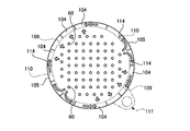
- FIG. 1 is a sectional view of a cooling device for a control rod drive device showing a cooling structure of a control rod drive device according to a first embodiment of the present invention
- FIG. 2 is a sectional view taken along line II-II in FIG. 1
- FIG. 4 is a schematic perspective view of the cooling device for the control rod driving device of the first embodiment
- FIG. 5 is an outline of the second exhaust duct in the cooling device for the control rod driving device of the first embodiment.
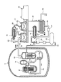
- FIG. 6 is a schematic configuration diagram of a nuclear power plant having a pressurized water reactor of Example 1
- FIG. 7 is a longitudinal sectional view showing the pressurized water reactor of Example 1
- FIG. It is principal part sectional drawing showing the control rod drive device in a pressurized water reactor.
- the nuclear reactor of Example 1 uses light water as a reactor coolant and a neutron moderator, and produces high-temperature and high-pressure water that does not boil over the entire core, and sends this high-temperature and high-pressure water to a steam generator to generate steam by heat exchange.
- This is a pressurized water reactor (PWR) that sends this steam to a turbine generator to generate electricity.
- PWR pressurized water reactor
- a pressurized water reactor 12 and a steam generator 13 are stored in the reactor containment vessel 11.
- the reactor 12 and the steam generator 13 are connected via cooling water pipes (coolant supply pipe systems) 14 and 15, a pressurizer 16 is provided in the cooling water pipe 14, and the cooling water is supplied to the cooling water pipe 15.
- a pump 15a is provided.
- light water is used as the moderator and primary cooling water, and the primary cooling system is controlled by the pressurizer 16 so as to maintain a high pressure state of about 150 to 160 atm in order to suppress boiling of the primary cooling water in the core. is doing.
- the pressurized water reactor 12 light water is heated as the primary cooling water by the low-enriched uranium or MOX as the fuel (nuclear fuel), and the high-temperature primary cooling water is cooled in a state maintained at a predetermined high pressure by the pressurizer 16. It is sent to the steam generator 13 through the water pipe 14. In the steam generator 13, heat exchange is performed between the high-pressure and high-temperature primary cooling water and the secondary cooling water, and the cooled primary cooling water is returned to the pressurized water reactor 12 through the cooling water pipe 15.
- the steam generator 13 is connected to a steam turbine 17 via a cooling water pipe 18, and the steam turbine 17 includes a high pressure turbine 19 and a low pressure turbine 20, and a generator 21 is connected thereto. Further, a moisture separation heater 22 is provided between the high pressure turbine 19 and the low pressure turbine 20, and a cooling water branch pipe 23 branched from the cooling water pipe 18 is connected to the moisture separation heater 22. On the other hand, the high pressure turbine 19 and the moisture separation heater 22 are connected by a low temperature reheat pipe 24, and the moisture separation heater 22 and the low pressure turbine 20 are connected by a high temperature reheat pipe 25.
- the low-pressure turbine 20 of the steam turbine 17 has a condenser 26, and a condenser pipe 26 and a drain pipe 28 for supplying and discharging cooling water (for example, seawater) are connected to the condenser 26.
- the condenser 26 is connected to a deaerator 30 through a cooling water pipe 29, and a condensate pump 31 and a low-pressure feed water heater 32 are provided in the cooling water pipe 29.
- the deaerator 30 is connected to the steam generator 13 via a cooling water pipe 33, and a water supply pump 34 and a high-pressure feed water heater 35 are provided in the cooling water pipe 33.
- the steam generated by performing heat exchange with the high-pressure and high-temperature primary cooling water in the steam generator 13 is sent to the steam turbine 17 (from the high-pressure turbine 19 to the low-pressure turbine 20) through the cooling water pipe 18, and this steam is generated. Then, the steam turbine 17 is driven to generate power by the generator 21. At this time, the steam from the steam generator 13 drives the high pressure turbine 19, and then the moisture contained in the steam is removed and heated by the moisture separator / heater 22, and then the low pressure turbine 20 is driven.
- the steam that drives the steam turbine 17 is cooled by the condenser 26 to become condensed water, heated by the low-pressure feed water heater 32 by, for example, the low-pressure steam extracted from the low-pressure turbine 20, and dissolved by the deaerator 30. After impurities such as oxygen and uncondensed gas (ammonia gas) are removed, the high pressure feed water heater 35 heats the high pressure steam extracted from, for example, the high pressure turbine 19 and then returns to the steam generator 13.
- a reactor vessel 41 has a reactor vessel main body 42 and a reactor vessel mounted on the reactor vessel main body 42 so that a reactor internal structure can be inserted therein.
- a lid 43 is formed, and the reactor vessel lid 43 can be opened and closed with respect to the reactor vessel body 42.
- the reactor vessel main body 42 has a cylindrical shape with an upper portion opened and a lower portion closed in a spherical shape, and an inlet nozzle 44 and an outlet nozzle 45 for supplying and discharging light water (coolant) as primary cooling water are formed on the upper portion.
- a cylindrical reactor core 46 having a cylindrical shape is disposed below the inlet nozzle 44 and the outlet nozzle 45 with a predetermined gap from the inner surface of the reactor vessel main body 42.
- An upper core plate 47 having a disk shape and a large number of communication holes (not shown) is connected to the upper portion of the slab, and a plurality of communication holes (similar to a disk shape and not shown) are formed at the bottom.
- a lower core plate 48 is connected.
- an upper core support plate 49 having a disk shape is fixed above the core tank 46, and a plurality of core support rods 50 are connected to the upper core support plate 49 from the upper core support plate 49.
- the upper core plate 47, that is, the core tank 46 is supported by being suspended.
- the lower core plate 48, that is, the core tank 46 is positioned and held by a plurality of radial keys 52 with respect to the inner surface of the reactor vessel main body 42.
- a core 53 is formed by the core tank 46, the upper core plate 47, and the lower core plate 48, and a large number of fuel assemblies 54 are arranged in the core 53.
- the fuel assembly 54 is configured by bundling a large number of fuel rods in a lattice shape by a support lattice, and an upper nozzle is fixed to the upper end portion, while a lower nozzle is fixed to the lower end portion.
- the plurality of control rods 55 are combined at the upper end portion into a control rod cluster 56 that can be inserted into the fuel assembly 54.
- a number of control rod cluster guide tubes 57 are supported by the upper core support plate 49 through the upper core support plate 49, and the lower end portion extends to the control rod cluster 56 of the fuel assembly 54. .
- a magnetic jack control rod drive device 58 is provided and accommodated in a housing 59 that is integrated with the reactor vessel lid 43.
- the upper ends of the control rod cluster guide tubes 57 extend to the control rod drive device 58, and the control rod cluster drive shaft 60 extends from the control rod drive device 58 in the control rod cluster guide tube 57.
- the control rod cluster 56 can be gripped by extending to the fuel assembly 54.
- the upper core support plate 49 supports a number of in-core instrumentation guide pipes through the upper core support plate 49, and the lower end portion extends to the fuel assembly 54. It is possible to insert a sensor that can measure the neutron flux.
- the control rod drive device 58 extends in the vertical direction and is connected to the control rod cluster 56 and has a control rod cluster drive shaft (having a plurality of circumferential grooves arranged at equal pitches in the longitudinal direction on the surface thereof. Hereinafter, it is referred to as a drive shaft.)
- the output of the nuclear reactor is controlled by moving 60 up and down with a magnetic jack.
- the drive shaft 60 has a plurality of circumferential grooves 60a formed on the surface thereof at equal pitches in the longitudinal direction, and is movable in the axial direction within the drive shaft housing 61 having a cylindrical shape. It has become.
- a fixed grip latch 62 provided in one of the circumferential grooves 60 a of the drive shaft 60 so as to be able to be engaged and disengaged, and a fixed grip coil 65 for driving the fixed grip latch 62 via the latch link 63 and the plunger 64 are provided.
- a holding mechanism 66 for holding the drive shaft 60 in the vertical direction by engaging the fixed grip latch 62 with the circumferential groove 60a is provided.
- a movable grip latch 67 provided to be disengageable from one of the peripheral grooves 60 a of the drive shaft 60, a movable grip coil 70 that drives the movable grip latch 67 via a latch link 68 and a plunger 69, and a latch link 68.
- a raising coil 71 for moving the plunger 69 in the vertical direction, and a drive mechanism 72 for moving the drive shaft 60 up and down is provided.
- 73 is a fixed handle magnetic pole excited by the fixed gripping coil 65
- 74 is a movable handle magnetic pole excited by the movable gripping coil 70
- 75 is a raised magnetic pole excited by the raising coil 71.
- Reference numerals 76a to 76c denote return springs.
- the fixed gripping magnetic pole 73 is demagnetized by the fixed gripping coil 65 and the fixed gripping latch 62 is separated from the circumferential groove 60 a of the drive shaft 60, while the movable gripping magnetic pole 74 is excited by the movable gripping coil 70 and the movable gripping latch 67.
- the raising magnetic pole 75 is excited by the raising coil 71
- the movable handle magnetic pole 74 and the movable gripping latch 67 together with the movable gripping coil 70 resist the biasing force of the return spring 76 a. Then, it is attracted to the raising magnetic pole 75 side, and the drive shaft 60 can be raised by one pitch.
- the movable gripping magnetic pole 74 is demagnetized and raised by the movable gripping coil 70.
- the raised magnetic pole 75 is demagnetized by the coil 71
- the movable grip latch 67 is separated from the circumferential groove 60a of the drive shaft 60, and the movable handle magnetic pole 74 and the movable grip latch 67 together with the movable grip coil 70 are urged by the return spring 76a. Can descend.
- the stationary gripping magnetic pole 73 is demagnetized by the stationary gripping coil 65 and the fixed gripping latch.
- the drive shaft 60 can be raised to a predetermined pitch by repeating the above-described operation from a state where the 62 is separated from the circumferential groove 60a of the drive shaft 60. In order to lower the drive shaft 60, the reverse operation of the above-described operation may be performed.
- the control rod drive device 58 moves the control rod cluster drive shaft 60 and inserts the control rod 55 into the fuel assembly 54, thereby controlling the nuclear fission in the core 53 and generating the generated heat.
- Light water filled in the reactor vessel 41 is heated by energy, and high-temperature light water is discharged from the outlet nozzle 45 and sent to the steam generator 13 as described above. That is, uranium or plutonium as the fuel constituting the fuel assembly 54 is fissioned to release neutrons, and the moderator and the light water as the primary cooling water reduce the kinetic energy of the released fast neutrons to produce thermal neutrons. And make it easier to cause new fission and take away the generated heat to cool. Further, by inserting the control rod 55 into the fuel assembly 54, the number of neutrons generated in the core 53 is adjusted, and when the reactor is urgently stopped, it is rapidly inserted into the core 53.
- an upper plenum 81 communicating with the outlet nozzle 45 is formed above the core 53, and a lower plenum 82 is formed below.
- a downcomer portion 83 communicating with the inlet nozzle 44 and the lower plenum 82 is formed between the nuclear reactor vessel 41 and the reactor core 46. Accordingly, light water flows into the reactor vessel main body 42 from the four inlet nozzles 44, flows down the downcomer portion 83, reaches the lower plenum 82, and is guided upward by the spherical inner surface of the lower plenum 82. And then flows into the core 53 after passing through the lower core plate 48.
- the light water that has flowed into the core 53 absorbs heat energy generated from the fuel assemblies 54 constituting the core 53 to cool the fuel assemblies 54, while passing through the upper core plate 47 at a high temperature. Ascending to the upper plenum 81 and discharged through the outlet nozzle 45.
- the pressurized water reactor 12 configured as described above is provided with a cooling device that cools the control rod driving device 58.
- the housing 59 includes an intake section 102, a work opening 103, a first exhaust duct 104, a second exhaust duct 105, and a third exhaust.
- a side wall is formed by connecting the duct 106 and a ceiling wall 107 is connected to the upper part.
- a plurality of magnetic jacks constituting the control rod driving device 58 are accommodated in the housing 59.
- the cooling device according to the present embodiment is a suction exhaust type in which cooling air is sucked into the housing 59 from the outside by driving an exhaust fan 113 of a discharge unit 111 (described later) provided in the housing 59. .
- the third exhaust duct 106 provided at the top is hollow and has a ring shape.
- the intake section 102 is an opening through which cooling air can be taken from the outside, and a filter is attached to each opening.
- the work opening 103 is an opening for an operator to enter the housing 59 at the time of inspection work, maintenance work, etc., and is closed by the opening / closing door 108 when not in use, and this opening / closing door 108 is used at the time of use. Is released.
- the intake portion 102 and the work opening 103 are arranged vertically so that the work opening 103 is positioned below the intake portion 102, and are opposed to the radial direction of the housing 59 in two sets at equal intervals in the circumferential direction. Is provided.
- the first exhaust duct 104 sucks the cooling air in the housing 59 from the lower first suction port 109 and guides it upward, and is disposed along the vertical direction of the housing 59 and in the circumferential direction. A plurality are arranged side by side.
- the first exhaust duct 104 is disposed between the two sets of the air intake portion 102 and the work opening portion 103 in the circumferential direction of the housing 59. That is, the intake portion 102, the work opening 103, and the first exhaust duct 104 are arranged side by side in the circumferential direction of the housing 59.
- the second exhaust duct 105 is disposed below the intake portion 102 and the work opening 103, and sucks the cooling air in the housing 59 from the second intake port 110 and guides it to the first exhaust duct 104. It is disposed along the circumferential direction of the housing 59.
- a duct member having a hollow ring shape and a plurality of suction ports formed in the inner peripheral portion is arranged at the lower end portion of the housing 59, and the lower end portions of the plurality of first exhaust ducts 104 are arranged.
- the first exhaust duct 104 and the second exhaust duct 105 are integrally formed by connecting to the upper surface portion of the duct member and communicating the inside. That is, the duct member constitutes a part of the first exhaust duct 104 and the second exhaust duct 105.
- a discharge part 111 for discharging the cooling air in the first exhaust duct 104 to the outside is provided.
- a connected exhaust duct 112 is connected to the outer periphery of the third exhaust duct 106, and an exhaust fan 113 is provided in the connected exhaust duct 112.
- the ceiling wall 107 of the housing 59 is formed with a mounting hole 107a in which each magnetic jack of the control rod driving device 58 is mounted.
- the housing 59 has a plurality of pillars 114 along the vertical direction arranged in parallel in the circumferential direction at equal intervals.
- the plurality of pillars 114 function as structures, and in this embodiment, the pillars 114 are made of a steel material having an H-shaped cross section. That is, the intake portion 102, the working opening 103, the first exhaust duct 104, the second exhaust duct 105, the third exhaust duct 106, and the like are supported by the plurality of pillars 114, thereby ensuring a predetermined strength. ing.
- the second exhaust duct 105 passes through the column 114 and communicates with the first exhaust duct 104.
- second exhaust ducts 115 (105 a, 105 b) are arranged on both sides in the circumferential direction with respect to the column 114 in the middle position in the circumferential direction in the intake portion 102.
- the second exhaust ducts 105a and 105b are formed at the base end portions thereof with second suction ports 110a and 110b that open into the housing 59, while the distal end portions thereof are connected to the first exhaust duct via the plurality of pillars 114. It is extended to 104.
- each pillar 114 located in the middle of the second exhaust ducts 105a and 105b is formed with a narrow through-hole 114a that is smaller than the flow passage area of the second exhaust ducts 105a and 105b. .
- the suction force is supplied from the third exhaust duct 106 to the first.
- suction force is generated in the housing 59 from the third exhaust duct 106 through the first exhaust duct 104 and through the second suction port 110 of the second exhaust duct 105. Act on. Further, the suction force acting in the housing 59 acts on the two intake portions 102.
- cooling air is taken into the housing 59 from each intake portion 102 as cooling air.
- the cooling air taken into the housing 59 from each intake portion 102 descends the inside of the housing 59 and passes through the coils 65, 70, 71 (see FIG. 8) of each magnetic jack of the cooling device 101 for the control rod driving device. Cooling. Cooling air whose temperature has risen by cooling the coils 65, 70, 71 is sucked into the first suction port 109 and the second suction port 110 where suction force acts by the exhaust fan 113 of the discharge unit 111, and the inside of the housing 59.
- the cooling air taken into the housing 59 from each intake portion 102 is sucked from the suction ports 109 and 110 provided at most positions in the circumferential direction in the lower portion of the housing 59 and is then exhausted to the exhaust duct 104. , 105. Therefore, the cooling air appropriately flows in the housing 59 from the central portion to the outer peripheral side and circulates almost uniformly throughout the inside, and the plurality of magnetic jacks are cooled uniformly and efficiently.
- the housing 59 that houses the magnetic jack is fixed to the upper portion of the reactor vessel 41, and the intake portion 102 that takes in the cooling air into the housing 59.
- a first exhaust duct 104 that is arranged in the circumferential direction of the intake portion 102 and the housing 59 and sucks the cooling air in the housing 59 from the lower first intake port 109 and guides it upward, and is disposed below the intake portion 102.
- the second exhaust duct 105 that sucks the cooling air in the housing 59 from the second suction port 110 and guides it to the first exhaust duct 104, and the cooling air in the first exhaust duct 104 provided on the upper portion of the housing 59 to the outside.
- a discharge unit 111 for discharging is provided.
- the cooling air taken into the housing 59 from the air intake portion 102 is sucked into the lower portion of the housing 59 from the suction ports 109 and 110 provided at almost the circumferential position, and the exhaust ducts 104 and 105 are taken. Then, it is discharged to the outside through the discharge unit 111. Therefore, the cooling air circulates almost uniformly throughout the entire area of the housing 59, and can cool a plurality of magnetic jacks uniformly and efficiently, improving the cooling efficiency of the control rod drive device 58. Can be achieved.
- a plurality of columns 114 as a structure body extending in the vertical direction are arranged in the housing 59 at predetermined intervals in the circumferential direction, and the flow path of the second exhaust duct 105 is formed in this manner.
- the column 114 passes through and communicates with the first exhaust duct 104. Therefore, the second exhaust duct 104 can be disposed while maintaining the pillar 114, and the cooling efficiency of the control rod drive device 58 can be improved while suppressing the strength reduction of the housing 59.
- a through-hole 114a having a smaller flow area than the flow path of the second exhaust duct 105 is formed in the column 114 in the middle of the second exhaust duct 105, so that the strength reduction of the pillar 114 can be reduced as much as possible. it can.
- the work opening 103 that can be opened and closed is provided below the intake portion 102 in the housing 59, and the second suction port 110 is provided below the work opening 103. Provided. Therefore, even if the working opening 103 is provided in addition to the intake portion 102, the cooling air in the housing 59 flows from the suction ports 109 and 110 provided at almost the position in the circumferential direction at the lower portion in the housing 59. Since the air is sucked and discharged to the outside, the cooling air can circulate substantially uniformly throughout the interior of the housing 59.
- the exhaust fan 113 is provided in the discharge unit 111. Therefore, by driving the exhaust fan 113, negative pressure can be applied to the housing 59 from the first exhaust duct 104 and the second exhaust duct 105 through the suction ports 109 and 110. Therefore, the cooling air in the housing 59 can be forcibly discharged to the outside, and the retention of the cooling air in the housing 59 can be suppressed, and the cooling efficiency of the control rod drive device 58 can be improved.
- the cooling method of the control rod drive device of the first embodiment after cooling air is taken into the inside from the upper side wall of the housing 59 that houses the magnetic jack, and the magnetic jack is cooled while the cooling air is lowered.
- the internal cooling air is taken out from the entire periphery of the lower part of the side wall of the housing 59 into the exhaust ducts 103 and 104, is raised through the exhaust ducts 103 and 104, and is then discharged to the outside by the exhaust fan 113. Accordingly, the cooling air circulates almost uniformly throughout the entire area of the housing 59, and a plurality of magnetic jacks can be cooled uniformly and efficiently, improving the cooling efficiency of the control rod drive device. Can be planned.
- a reactor vessel 41 a reactor vessel 41, a core tank 46, a core 53, a plurality of control rods 55, a control rod driving device 58, and a cooling device 101 for the control rod driving device are provided.
- a cooling device 101 for the control rod driving device a housing 59 that houses a magnetic jack is fixed to the upper portion of the reactor vessel 41, and an intake portion 102 that takes cooling air into the housing 59, an intake portion 102, and a housing 59
- the first exhaust duct 104 that guides the cooling air in the housing 59 from the lower first suction port 109 and guides the cooling air in the circumferential direction, and the cooling air in the housing 59 arranged below the intake portion 102.
- the cooling air taken into the housing 59 from the air intake portion 102 is sucked into the lower portion of the housing 59 from the suction ports 109 and 110 provided at almost the circumferential position, and the exhaust ducts 104 and 105 are taken. Then, it is discharged to the outside through the discharge unit 111. Therefore, the cooling air circulates almost uniformly throughout the entire area of the housing 59, and can cool a plurality of magnetic jacks uniformly and efficiently, improving the cooling efficiency of the control rod drive device 58. As a result, highly accurate power control of the nuclear reactor can be realized.
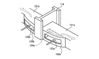
- FIG. 9 is a schematic diagram of the second exhaust duct in the cooling device for the control rod drive device, which represents the cooling structure of the control rod drive device according to the second embodiment of the present invention.
- the overall structure of the cooling structure of the control rod driving device of this embodiment is substantially the same as that of the first embodiment described above, and will be described with reference to FIGS. 1 to 4 and the same as that described in this embodiment.
- the members having the above functions are denoted by the same reference numerals and redundant description is omitted.
- the housing 59 includes an intake portion 102, a work opening 103, a first exhaust duct 104, and second exhaust ducts 121 a and 121 b. (Refer FIG. 9) and the 3rd exhaust duct 106 are connected, a side wall is comprised, and the ceiling wall 107 is comprised by the upper part.
- a plurality of magnetic jacks constituting the control rod driving device 58 are accommodated in the housing 59.
- the air intake portion 102 and the work opening portion 103 are arranged vertically so that the work opening portion 103 is positioned below the air intake portion 102, and the air intake portion 102 and the work opening portion 103 face the radial direction of the housing 59 at equal intervals in the circumferential direction.
- a set is provided.
- the first exhaust duct 104 is disposed between the two sets of the air intake portion 102 and the work opening portion 103 in the circumferential direction of the housing 59. That is, the intake portion 102, the work opening 103, and the first exhaust duct 104 are arranged side by side in the circumferential direction of the housing 59.
- the second exhaust ducts 121 a and 121 b are positioned below the intake portion 102 and the work opening 103 and are disposed along the circumferential direction of the housing 59.
- the cooling air in the housing 59 is sucked and led to the first exhaust duct 104.
- a discharge part 111 for discharging the cooling air moved from the first exhaust duct 104 to the third exhaust duct 106 is provided.
- the housing 59 has a plurality of pillars 114 along the vertical direction arranged in parallel in the circumferential direction at equal intervals.
- Second exhaust ducts 121a and 121b are arranged on both sides in the circumferential direction with respect to the column 114 located at the intermediate position in the circumferential direction in the intake section 102.
- projecting portions 122a and 122b projecting inward of the housing 59 are integrally formed at the base end portions of the second exhaust ducts 121a and 121b.
- second suction ports 123 a and 123 b that suck the cooling air in the housing 59 and guide it to the first exhaust duct 104 are formed in front portions of the projecting portions 122 a and 122 b.
- the second suction port 124a may be formed not only on the front surfaces of the protrusions 122a and 122b but also on the upper surface.
- the tip ends of the second exhaust ducts 121a and 121b are extended to the first exhaust duct 104 via a plurality of columns 114, and each column 114 located in the middle of the second exhaust ducts 121a and 121b includes As in the first embodiment, a through hole (not shown) is formed.
- the suction force is supplied from the third exhaust duct 106 to the housing through the first intake port 109 of the first exhaust duct 104.
- the suction force acts in the housing 59 from the third exhaust duct 106 through the first exhaust duct 104 and through the second suction ports 123a and 123b of the second exhaust ducts 121a and 121b. Further, the suction force acting in the housing 59 acts on the two intake portions 102.
- each magnetic jack of the cooling device 101 for the control rod drive device is cooled while descending the inside of the housing 59. Cooling air that has cooled each magnetic jack is sucked into the first suction port 109 and directly sucked into the first exhaust duct 104 from the housing 59, and sucked into the second suction ports 123a and 123b. To the first exhaust duct 104 through the second exhaust ducts 121a and 121b. The cooling air sucked into each first exhaust duct 104 rises inside, flows into the third exhaust duct 106, and is discharged from the discharge unit 111 to the outside.
- the cooling air taken into the housing 59 from each intake portion 102 is sucked from the suction ports 109, 123a, and 123b provided at most positions in the circumferential direction in the lower portion of the housing 59 to be exhausted. It flows into the ducts 104, 121a, 121b. Therefore, the cooling air appropriately flows in the housing 59 from the central portion to the outer peripheral side and circulates almost uniformly throughout the inside, and the plurality of magnetic jacks are cooled uniformly and efficiently.
- the intake air 102 that introduces the cooling air into the housing 59, and the cooling air inside the housing 59 aligned in the circumferential direction of the intake air portion 102 and the housing 59.
- the first exhaust duct 104 that sucks the air from the lower first suction port 109 and guides it upward, and the cooling air in the housing 59 that is disposed below the suction portion 102 is sucked from the second suction ports 123a and 123b to be first.
- Second exhaust ducts 121a and 121b that lead to the first exhaust duct 104 and a discharge unit 111 that is provided above the housing 59 and discharges the cooling air in the first exhaust duct 104 to the outside.
- the cooling air taken into the housing 59 from the intake portion 102 is sucked from the suction ports 109, 123 a, 123 b provided at most positions in the circumferential direction in the lower portion of the housing 59, and the exhaust ducts 104. , 121a, 121b are discharged to the outside through the discharge unit 111. Therefore, the cooling air circulates almost uniformly throughout the entire area of the housing 59, and can cool a plurality of magnetic jacks uniformly and efficiently, improving the cooling efficiency of the control rod drive device 58. Can be achieved.
- the projecting portions 122a and 122b projecting to the inner side of the housing 59 are provided at the base end portions of the second exhaust ducts 121a and 121b, and the projecting portions 122a and 122b are provided.
- the second suction ports 123a and 123b are formed. Therefore, by expanding the opening area of the second suction ports 123a and 113b and sufficiently ensuring the suction capacity of cooling air from the housing 59 to the second exhaust ducts 121a and 121b, the inside of the housing 59 can be increased. It is possible to suppress the stagnation of the cooling air in the control rod and improve the cooling efficiency of the control rod driving device 58.
- FIG. 10 is a schematic view of the second exhaust duct in the cooling device for the control rod driving device, which represents the cooling structure of the control rod driving device according to the third embodiment of the present invention.
- the overall structure of the cooling structure of the control rod driving device of this embodiment is substantially the same as that of the first embodiment described above, and will be described with reference to FIGS. 1 to 4 and the same as that described in this embodiment.
- the members having the above functions are denoted by the same reference numerals and redundant description is omitted.
- the housing 59 includes an intake portion 102, a work opening 103, a first exhaust duct 104, and second exhaust ducts 132 a and 132 b. (See FIG. 10) and the third exhaust duct 106 are connected to form a side wall, and a ceiling wall 107 is connected to the upper part.
- a plurality of magnetic jacks constituting the control rod driving device 58 are accommodated in the housing 59.
- the air intake portion 102 and the work opening portion 103 are arranged vertically so that the work opening portion 103 is positioned below the air intake portion 102, and the air intake portion 102 and the work opening portion 103 face the radial direction of the housing 59 at equal intervals in the circumferential direction.
- a set is provided.
- the first exhaust duct 104 is disposed between the two sets of the air intake portion 102 and the work opening portion 103 in the circumferential direction of the housing 59. That is, the intake portion 102, the work opening 103, and the first exhaust duct 104 are arranged side by side in the circumferential direction of the housing 59.
- the second exhaust ducts 132 a and 132 b are located below the intake portion 102 and the working opening 103 and are disposed along the circumferential direction of the housing 59.
- the cooling air in the housing 59 is sucked and led to the first exhaust duct 104.
- a discharge part 111 for discharging the cooling air moved from the first exhaust duct 104 to the third exhaust duct 106 is provided.
- the housing 59 has a plurality of columns 131 arranged in the vertical direction along the inside in a circumferential direction.
- the plurality of pillars 131 function as a structure, and in this embodiment, the pillars 131 are made of reinforced concrete having a hollow shape. That is, the intake portion 102, the working opening 103, the first exhaust duct 104, the second exhaust ducts 132a and 132b, the third exhaust duct 106, and the like are supported by the plurality of pillars 131, so that a predetermined strength is obtained. It is secured.
- the second exhaust ducts 132a and 132b are arranged on both sides in the circumferential direction with respect to the column 131 at the circumferential intermediate position in the intake section 102.
- the second exhaust ducts 132a and 132b are formed at the base end portions thereof with second suction ports 133a and 133b that open into the housing 59, while the distal end portions of the second exhaust ducts 132a and 132b are connected to the first exhaust duct via the plurality of columns 131.
- a through hole (not shown) is formed in each pillar 131 that extends to 104 and is located in the middle of the second exhaust ducts 132a and 132b.
- each magnetic jack of the cooling device 101 for the control rod driving device is cooled while descending. Cooling air that has cooled each magnetic jack is sucked into the first suction port 109 and directly sucked into the first exhaust duct 104 from the housing 59, and is sucked into the second suction ports 133a and 133b. To the first exhaust duct 104 through the second exhaust ducts 132a and 132b. The cooling air sucked into each first exhaust duct 104 rises inside, flows into the third exhaust duct 106, and is discharged from the discharge unit 111 to the outside.
- the cooling air taken into the housing 59 from each intake portion 102 is sucked from the suction ports 109, 133 a, 133 b provided at most positions in the circumferential direction in the lower portion of the housing 59 to be exhausted from the exhaust air. It flows into the ducts 104, 132a, 132b. Therefore, the cooling air appropriately flows in the housing 59 from the central portion to the outer peripheral side and circulates almost uniformly throughout the inside, and the plurality of magnetic jacks are cooled uniformly and efficiently.
- a plurality of columns 131 made of reinforced concrete having a hollow shape as a structure are arranged side by side in the circumferential direction, and the air intake portion 102 and the work opening portion are provided.
- the first exhaust duct 104, the second exhaust ducts 132 a and 132 b, and the third exhaust duct 106 are supported by the plurality of pillars 131 to form a housing 59.
- the housing 59 including the intake portion 102, the working opening 103, the first exhaust duct 104, the second exhaust ducts 132a and 132b, and the third exhaust duct 106, and each exhaust duct.
- 104, 132a, 132b, 106 can be efficiently arranged, and the cooling efficiency of the control rod drive device 58 can be improved.
- FIG. 11 is a schematic diagram of the second exhaust duct in the cooling device for the control rod drive device, which represents the cooling structure of the control rod drive device according to the fourth embodiment of the present invention.
- the overall structure of the cooling structure of the control rod driving device of this embodiment is substantially the same as that of the first embodiment described above, and will be described with reference to FIGS. 1 to 4 and the same as that described in this embodiment.
- the members having the above functions are denoted by the same reference numerals and redundant description is omitted.
- the housing 59 has a plurality of columns 131 extending in the vertical direction arranged in parallel at equal intervals in the circumferential direction. Yes.
- the intake portion 102, the working opening 103, the first exhaust duct 104, the second exhaust ducts 132 a and 132 b, the third exhaust duct 106, and the like are supported by the plurality of pillars 131, thereby ensuring a predetermined strength. ing.
- the second exhaust ducts 132a and 132b are arranged on both sides in the circumferential direction with respect to the column 131 at the circumferential intermediate position in the intake section 102.
- the column 131 at the intermediate position is formed with a third suction port 134 that opens into the housing 59.
- the base ends of the second exhaust ducts 132a and 132b are connected to the surface of the column 131 and communicate with each other through a through hole.
- second suction ports 133a and 133b that open into the housing 59 are formed at the base end portions of the second exhaust ducts 132a and 132b, respectively, and the distal end portion of the second exhaust ducts 132a and 132b is connected to the first exhaust duct via a plurality of columns 131. It is extended to 104.
- each magnetic jack of the cooling device 101 for the control rod driving device is cooled while descending. Cooling air that has cooled each magnetic jack is sucked into the first suction port 109 and directly sucked into the first exhaust duct 104 from the inside of the housing 59, and also into the second suction ports 133 a and 133 b and the third suction port 134. The air is sucked and sucked into the first exhaust duct 104 from the housing 59 through the second exhaust ducts 132a and 132b. The cooling air sucked into each first exhaust duct 104 rises inside, flows into the third exhaust duct 106, and is discharged from the discharge unit 111 to the outside.
- the cooling air taken into the housing 59 from each intake portion 102 is sucked from the suction ports 109, 133 a, 133 b, and 134 provided at most positions in the circumferential direction in the lower portion of the housing 59. It flows into each exhaust duct 104, 132a, 132b. Therefore, the cooling air appropriately flows in the housing 59 from the central portion to the outer peripheral side and circulates almost uniformly throughout the inside, and the plurality of magnetic jacks are cooled uniformly and efficiently.
- the first exhaust duct 104 that sucks air from the lower first suction port 109 and guides it upward, and the cooling air in the housing 59 that is disposed below the suction portion 102 is sucked from the second suction ports 132a and 132b and is A plurality of second exhaust ducts 131 a and 131 b that lead to one exhaust duct 104 and a discharge portion 111 that is provided on the top of the housing 59 and discharges the cooling air in the first exhaust duct 104 to the outside, and also supports the housing 59.
- a third suction port 134 communicating with the second exhaust ducts 132a and 132b is provided in a part of the column 131.
- the cooling air taken into the housing 59 from the intake portion 102 is sucked from the suction ports 109, 133a, 133b, and 134 provided at almost the lower position in the housing 59 in the circumferential direction, and the exhaust air is exhausted. From the ducts 104, 132a, and 132b, the air is discharged to the outside through the discharge portion 111. Therefore, the cooling air circulates almost uniformly throughout the entire area of the housing 59, and can cool a plurality of magnetic jacks uniformly and efficiently, improving the cooling efficiency of the control rod drive device 58. Can be achieved.
- the second exhaust ducts 132a and 132b can be disposed while maintaining the pillar 131, and the provision of the third suction port 134 can suppress the retention of cooling air in the housing 59, and The strength reduction of the housing 59 can be suppressed.
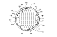
- FIG. 12 is a horizontal cross-sectional view of a cooling device for a control rod driving device showing a cooling structure of the control rod driving device according to Embodiment 5 of the present invention.
- the overall structure of the cooling structure of the control rod driving device of this embodiment is substantially the same as that of the first embodiment described above, and will be described with reference to FIGS. 1, 2, 4, and 4. Members having the same functions as those described above are denoted by the same reference numerals and redundant description is omitted.
- the cooling structure of the control rod drive device in the fifth embodiment is different from the first embodiment only in the configuration of the first exhaust duct. Therefore, the entire structure of the cooling device for the control rod driving device will be described with reference to FIGS. 1, 2, and 4, and details of the first exhaust duct will be described with reference to FIG.
- the housing 59 includes an intake portion 102, a work opening 103, a first exhaust duct 104, and a second exhaust duct. 105 and the third exhaust duct 106 are connected to form a side wall, and a ceiling wall 107 is connected to the upper part. A plurality of magnetic jacks constituting the control rod driving device 58 are accommodated in the housing 59.
- the air intake portion 102 and the work opening portion 103 are arranged vertically so that the work opening portion 103 is positioned below the air intake portion 102, and the air intake portion 102 and the work opening portion 103 face the radial direction of the housing 59 at equal intervals in the circumferential direction.
- a set is provided.
- the first exhaust duct 104 is disposed between the two sets of the air intake portion 102 and the work opening portion 103 in the circumferential direction of the housing 59. That is, the intake portion 102, the work opening 103, and the first exhaust duct 104 are arranged side by side in the circumferential direction of the housing 59.
- the second exhaust duct 105 is located below the intake portion 102 and the work opening 103 and is disposed along the circumferential direction of the housing 59.
- the second exhaust duct 105 sucks the cooling air in the housing 59 and takes the first exhaust duct. 104.
- a discharge part 111 for discharging the cooling air moved from the first exhaust duct 104 to the third exhaust duct 106 is provided.
- a perforated plate (flow rate adjusting member) 141 for adjusting the amount of air through which the cooling air flows is provided in a portion corresponding to the first suction port 109 in each first exhaust duct 104.
- the perforated plate 141 is composed of a metal plate or a metal mesh (net) having a large number of openings, and is formed on the outer side (of the housing 59) of the first exhaust duct 104. It is fixed on the inner side. Therefore, when the cooling air in the housing 59 is sucked into the first exhaust duct 104 from the first suction port 109, the porous plate 141 becomes a resistance and the flow rate is reduced.
- each magnetic jack of the cooling device 101 for the control rod driving device is cooled while descending.
- the cooling air that has cooled each magnetic jack is sucked into the first suction port 109 and directly sucked into the first exhaust duct 104 from the housing 59, and sucked into the second suction port 109 and then sucked into the first air from the housing 59. 2 is sucked into the first exhaust duct 104 via the exhaust duct 105.
- the cooling air sucked into each first exhaust duct 104 rises inside, flows into the third exhaust duct 106, and is discharged from the discharge unit 111 to the outside.
- the cooling air taken into the housing 59 from each intake portion 102 is sucked from the suction ports 109 and 110 provided at most positions in the circumferential direction in the lower portion of the housing 59 and is then exhausted to the exhaust duct 104. , 105. Therefore, the cooling air appropriately flows in the housing 59 from the central portion to the outer peripheral side and circulates almost uniformly throughout the inside, and the plurality of magnetic jacks are cooled uniformly and efficiently.
- the cooling air in the housing 59 is sucked into the first exhaust duct 104 from the first suction port 109, the flow rate is reduced by the perforated plate 141, so that the cooling air in the housing 59 becomes the second suction port 110. Therefore, the cooling air in the housing 59 is more likely to be circulated uniformly over the entire area.
- the first exhaust duct 104 that sucks air from the lower first suction port 109 and guides it upward, and the cooling air in the housing 59 that is disposed below the suction portion 102 is sucked from the second suction port 110 to be discharged first.
- a second exhaust duct 105 that leads to the duct 104 is provided, and a perforated plate 141 that adjusts the amount of air through which cooling air flows through the first suction port 109 in the first exhaust duct 104 is provided.
- the cooling air taken into the housing 59 from the air intake portion 102 is sucked into the lower portion of the housing 59 from the suction ports 109 and 110 provided at almost the circumferential position, and the exhaust ducts 104 and 105 are taken. Then, it is discharged to the outside through the discharge unit 111.
- the cooling air since the flow rate of the first suction port 109 is limited by the perforated plate 141, the cooling air easily passes through the second suction port 110 and is sucked into the first exhaust duct 104 from the first suction port 109.
- the amount of cooling air and the amount of cooling air sucked into the second exhaust duct 105 from the second suction port 110 are substantially the same. Therefore, the cooling air circulates almost uniformly throughout the entire area of the housing 59, and can cool a plurality of magnetic jacks uniformly and efficiently, improving the cooling efficiency of the control rod drive device 58. Can be achieved.
- FIG. 13 is a schematic diagram of the second exhaust duct in the cooling device for the control rod drive device, which represents the cooling structure of the control rod drive device according to the sixth embodiment of the present invention.
- the overall structure of the cooling structure of the control rod driving device of this embodiment is substantially the same as that of the first embodiment described above, and will be described with reference to FIGS. 1 to 4 and the same as that described in this embodiment.
- the members having the above functions are denoted by the same reference numerals and redundant description is omitted.
- the cooling structure of the control rod driving device in the sixth embodiment is different from the fourth embodiment only in the configuration of the second exhaust duct. Therefore, the entire structure of the cooling device for the control rod driving device will be described with reference to FIGS. 1 to 4, and the details of the second exhaust duct will be described with reference to FIG.
- the housing 59 has a plurality of columns 131 extending in the vertical direction arranged in parallel at equal intervals in the circumferential direction. Yes.
- the intake portion 102, the working opening 103, the first exhaust duct 104, the second exhaust ducts 132 a and 132 b, the third exhaust duct 106, and the like are supported by the plurality of pillars 131, thereby ensuring a predetermined strength. ing.
- the second exhaust ducts 132a and 132b are arranged on both sides in the circumferential direction with respect to the column 131 at the circumferential intermediate position in the intake section 102.
- the column 131 at the intermediate position is formed with a third suction port 134 that opens into the housing 59.
- the base ends of the second exhaust ducts 132a and 132b are connected to the surface of the column 131 and communicate with each other through a through hole.
- second suction ports 133a and 133b that open into the housing 59 are formed at the base end portions of the second exhaust ducts 132a and 132b, respectively, and the distal end portion of the second exhaust ducts 132a and 132b is connected to the first exhaust duct via a plurality of columns 131. It is extended to 104.
- a perforated plate (flow rate adjusting member) 151 for adjusting the amount of air through which the cooling air flows is provided in the flow path in each of the second exhaust ducts 132a and 132b.
- the perforated plate 151 is made of a metal plate or a metal mesh (net) having a large number of openings, and is fixed to a cooling air flow path in the second exhaust ducts 132a and 132b. Therefore, when the cooling air in the housing 59 flows from the second suction ports 133a and 133b to the first exhaust duct 104 through the second exhaust ducts 132a and 132b, the porous plate 151 becomes a resistance and the flow rate is reduced. It becomes.
- each magnetic jack of the cooling device 101 for the control rod driving device is cooled while descending. Cooling air that has cooled each magnetic jack is sucked into the first suction port 109 and directly sucked into the first exhaust duct 104 from the inside of the housing 59, and also into the second suction ports 133 a and 133 b and the third suction port 134. The air is sucked and sucked into the first exhaust duct 104 from the housing 59 through the second exhaust ducts 132a and 132b. The cooling air sucked into each first exhaust duct 104 rises inside, flows into the third exhaust duct 106, and is discharged from the discharge unit 111 to the outside.
- the cooling air taken into the housing 59 from each intake portion 102 is sucked from the suction ports 109, 133 a, 133 b, and 134 provided at most positions in the circumferential direction in the lower portion of the housing 59. It flows into each exhaust duct 104, 132a, 132b. Therefore, the cooling air appropriately flows in the housing 59 from the central portion to the outer peripheral side and circulates almost uniformly throughout the inside, and the plurality of magnetic jacks are cooled uniformly and efficiently.
- the cooling air in the housing 59 is sucked into the second exhaust ducts 132a and 132b from the second suction ports 133a and 133b and the third suction port 134, the flow rate is reduced by the porous plate 151.
- the cooling air in the housing is easily sucked into the first exhaust duct 104 from the first suction port 109, and the cooling air in the housing is further easily circulated throughout the entire area.
- the cooling air hardly flows into the second exhaust ducts 132a and 132b, but the second exhaust ducts 132a and 132b and the pillars
- the first exhaust duct 104 may be less likely to flow. In this case, the air flow rate is reduced by providing the perforated plate 151 in the second exhaust ducts 132a and 132b.
- porous plate 151 is provided in the air flow path in the second exhaust ducts 132a and 132b, a porous plate may be provided in part or all of the second suction ports 133a and 133b and the third suction port 134. In this case, the flow resistance value by the perforated plate 151 may be changed according to the flow of cooling air in the housing 59.
- the first exhaust duct 104 that sucks air from the lower first suction port 109 and guides it upward, and the cooling air in the housing 59 that is disposed below the suction portion 102 is sucked from the second suction ports 133a and 133b and is Second exhaust ducts 132a and 132b leading to one exhaust duct 104 are provided, and a perforated plate 151 for adjusting the amount of air through which cooling air flows is provided in the second exhaust ducts 132a and 132b.
- the cooling air taken into the housing 59 from the intake portion 102 is sucked from the suction ports 109, 133a, 133b, and 134 provided at almost the lower position in the housing 59 in the circumferential direction, and the exhaust air is exhausted. From the ducts 104, 132a, and 132b, the air is discharged to the outside through the discharge portion 111. At this time, since the flow rate of the second exhaust ducts 132 a and 132 b is limited by the perforated plate 151, the cooling air easily passes through the first suction port 109 and is sucked into the first exhaust duct 104 from the first suction port 109.
- the amount of cooling air to be sucked and the amount of cooling air sucked into the second exhaust ducts 132a and 132b from the second suction ports 133a and 133b are substantially the same. Therefore, the cooling air circulates almost uniformly throughout the entire area of the housing 59, and can cool a plurality of magnetic jacks uniformly and efficiently, improving the cooling efficiency of the control rod drive device 58. Can be achieved.
- the reactor containment vessel and the coolant supply piping system that supplies the coolant into the reactor containment vessel are provided, and steam is generated by heat exchange between the nuclear fuel and the coolant.
- the present invention can be applied to a nuclear reactor that generates power by driving a power generation turbine with generated steam, and is not limited to the above-described pressurized water reactor (PWR), but also to other types of nuclear reactors such as a boiling water reactor (BWR). Can also be applied.
- PWR pressurized water reactor
- BWR boiling water reactor
- the cooling structure and method of the control rod driving device and the nuclear reactor according to the present invention improve the cooling efficiency of the control rod driving device by providing the inlet of the exhaust duct for discharging the cooling air inside the housing at an appropriate position. It can be applied to any kind of nuclear reactor.
Landscapes
- Physics & Mathematics (AREA)
- Engineering & Computer Science (AREA)
- Chemical & Material Sciences (AREA)
- Chemical Kinetics & Catalysis (AREA)
- Plasma & Fusion (AREA)
- General Engineering & Computer Science (AREA)
- High Energy & Nuclear Physics (AREA)
- Monitoring And Testing Of Nuclear Reactors (AREA)
Abstract
Description
41 原子炉容器
46 炉心槽
53 炉心
54 燃料集合体
55 制御棒
57 制御棒クラスタ案内管
58 制御棒駆動装置
59 ハウジング
60 制御棒クラスタ駆動軸
101 制御棒駆動装置用冷却装置
102 吸気部
103 作業用開口部
104 第1排気ダクト
105,105a,105b,121a,121b,132a,132b 第2排気ダクト
106 第3排気ダクト
107 天井壁
109 第1吸入口
110,110a,110b,123a,123b,133a,133b 第2吸入口
111 排出部
112 連結排気ダクト
113 排気ファン
114,131 柱(構造体)
114a 貫通孔
122a,122b 突出部
134 第3吸入口
141,151 多孔板(流量調整部材)
Claims (11)
- 原子炉容器の上部に配置されて磁気式ジャッキにより炉心に対して制御棒を出し入れする制御棒駆動装置の冷却構造において、
前記原子炉容器の上部に固定されて前記磁気式ジャッキを収容するハウジングと、
該ハウジング内に冷却空気を取り入れる吸気部と、
前記吸気部と前記ハウジングの周方向に並んで配置されて該ハウジング内の冷却空気を下部の第1吸入口から吸入して上方に導く第1排気ダクトと、
前記吸気部の下方に配置されて前記ハウジング内の冷却空気を第2吸入口から吸入して前記第1排気ダクトに導く第2排気ダクトと、
前記ハウジングの上部に設けられて前記第1排気ダクト内の冷却空気を外部に排出する排出部と、
を備えることを特徴とする制御棒駆動装置の冷却構造。 - 前記ハウジングは、上下方向に沿う構造体が周方向に所定間隔で複数並設され、前記第2排気ダクトは、前記構造体を貫通して前記第1排気ダクトに連通することを特徴とする請求項1に記載の制御棒駆動装置の冷却構造。
- 前記構造体は、中空形状をなし、前記ハウジング内の冷却空気を吸入する第3吸入口が設けられると共に、貫通孔を通して前記第2排気ダクトに連通することを特徴とする請求項2に記載の制御棒駆動装置の冷却構造。
- 前記第2排気ダクトは、前記ハウジングの内部に突出する突出部を有し、該突出部に前記第2吸入口が設けられることを特徴とする請求項1から3のいずれか一つに記載の制御棒駆動装置の冷却構造。
- 前記第1吸入口に、冷却空気が流通する空気量を調整する流量調整部材が設けられることを特徴とする請求項1から4のいずれか一つに記載の制御棒駆動装置の冷却構造。
- 前記第2排気ダクトに、冷却空気が流通する空気量を調整する流量調整部材が設けられることを特徴とする請求項1から5のいずれか一つに記載の制御棒駆動装置の冷却構造。
- 前記ハウジングに、前記吸気部の下方に位置して開閉自在な作業用開口部が設けられ、該作業用開口部の下方に前記第2吸入口が設けられることを特徴とする請求項1から6のいずれか一つに記載の制御棒駆動装置の冷却構造。
- 前記排出部に排気ファンが設けられることを特徴とする請求項1から7のいずれか一つに記載の制御棒駆動装置の冷却構造。
- 原子炉容器の上部に配置されて磁気式ジャッキにより炉心に対して制御棒を出し入れする制御棒駆動装置の冷却方法において、
前記磁気式ジャッキを収容するハウジングの側壁上部から内部に冷却空気を取り入れ、
冷却空気を下降させながら前記磁気式ジャッキを冷却した後、
前記ハウジングの側壁下部の全周から内部の冷却空気を排気ダクトに取り出し、
該排気ダクトを通して上昇させた後、排気ファンにより外部に排出する、
ことを特徴とする制御棒駆動装置の冷却方法。 - 前記吸気部と前記ハウジングの周方向に並んで前記排気ダクトが配置され、前記磁気式ジャッキを冷却した冷却空気を、前記排気ダクトの下部に設けられた第1吸入口から吸入すると共に、前記吸気部の下方に設けられた第2吸入口から吸入し、前記排気ダクトを通して上昇させて排出することを特徴とする請求項9に記載の制御棒駆動装置の冷却方法。
- 原子炉容器と、該原子炉容器内に配置される炉心槽と、該炉心槽内に配置される炉心と、該炉心を制御する複数の制御棒と、前記原子炉容器の上部に配置されて磁気式ジャッキにより前記炉心に対して前記制御棒を出し入れする制御棒駆動装置と、冷却空気により該制御棒駆動装置を冷却する制御棒駆動装置用冷却装置とを備え、
原子燃料と冷却材との熱交換により蒸気を発生し、発生蒸気により発電タービンを駆動して発電を行う原子炉において、
前記制御棒駆動装置用冷却装置は、
前記原子炉容器の上部に固定されて前記磁気式ジャッキを収容するハウジングと、
該ハウジング内に冷却空気を取り入れる吸気部と、
前記吸気部と前記ハウジングの周方向に並んで配置されて該ハウジング内の冷却空気を下部の第1吸入口から吸入して上方に導く第1排気ダクトと、
前記吸気部の下方に配置されて前記ハウジング内の冷却空気を第2吸入口から吸入して前記第1排気ダクトに導く第2排気ダクトと、
前記ハウジングの上部に設けられて前記第1排気ダクト内の冷却空気を外部に排出する排出部と、
を有することを特徴とする原子炉。
Priority Applications (3)
| Application Number | Priority Date | Filing Date | Title |
|---|---|---|---|
| US12/866,983 US8711998B2 (en) | 2008-02-22 | 2009-02-20 | Cooling structure and cooling method for control rod drive mechanism and nuclear reactor |
| EP09713480.3A EP2246860B1 (en) | 2008-02-22 | 2009-02-20 | Cooling structure for a control rod drive mechanism |
| CN2009801060806A CN101952896A (zh) | 2008-02-22 | 2009-02-20 | 控制棒驱动装置的冷却结构、方法以及核反应堆 |
Applications Claiming Priority (2)
| Application Number | Priority Date | Filing Date | Title |
|---|---|---|---|
| JP2008042042A JP2009198400A (ja) | 2008-02-22 | 2008-02-22 | 制御棒駆動装置の冷却構造及び方法並びに原子炉 |
| JP2008-042042 | 2008-02-22 |
Publications (1)
| Publication Number | Publication Date |
|---|---|
| WO2009104745A1 true WO2009104745A1 (ja) | 2009-08-27 |
Family
ID=40985622
Family Applications (1)
| Application Number | Title | Priority Date | Filing Date |
|---|---|---|---|
| PCT/JP2009/053053 Ceased WO2009104745A1 (ja) | 2008-02-22 | 2009-02-20 | 制御棒駆動装置の冷却構造及び方法並びに原子炉 |
Country Status (6)
| Country | Link |
|---|---|
| US (1) | US8711998B2 (ja) |
| EP (1) | EP2246860B1 (ja) |
| JP (1) | JP2009198400A (ja) |
| KR (1) | KR20100102230A (ja) |
| CN (1) | CN101952896A (ja) |
| WO (1) | WO2009104745A1 (ja) |
Families Citing this family (7)
| Publication number | Priority date | Publication date | Assignee | Title |
|---|---|---|---|---|
| KR101086056B1 (ko) * | 2010-02-01 | 2011-11-22 | 한국전력기술 주식회사 | 경수로용 제어봉 구동장치의 냉각 유니트 |
| CN103871499B (zh) * | 2012-12-13 | 2016-08-10 | 中国核动力研究设计院 | 一种适用于一体化堆顶的crdm冷却围板及风管组件 |
| USD782274S1 (en) * | 2015-08-05 | 2017-03-28 | Roddie, Inc. | Rear gripper latch |
| KR102651527B1 (ko) * | 2017-12-29 | 2024-03-28 | 뉴스케일 파워, 엘엘씨 | 제어봉 구동 메커니즘의 구동 모터를 위한 냉각 챔버를 가진 원자로 모듈 |
| CN111933316B (zh) * | 2020-08-12 | 2023-06-02 | 三门核电有限公司 | 一种压水堆反应堆堆腔区域高效冷却的方法 |
| CN115331846B (zh) * | 2022-07-11 | 2025-06-13 | 中国核电工程有限公司 | 一种用于增强循环的堆顶通风冷却系统及冷却方法 |
| CN116487081B (zh) * | 2023-06-06 | 2025-11-14 | 上海核工程研究设计院股份有限公司 | 一种堆芯出口流量高度均匀的堆内构件及其设计方法 |
Citations (5)
| Publication number | Priority date | Publication date | Assignee | Title |
|---|---|---|---|---|
| JPS56122994A (en) * | 1980-02-08 | 1981-09-26 | Framatome Sa | Nuclear reactor control assembly |
| JPS61182895U (ja) * | 1985-05-07 | 1986-11-14 | ||
| JPH02108998A (ja) * | 1988-10-19 | 1990-04-20 | Mitsubishi Heavy Ind Ltd | 耐熱駆動コイル及び制御棒駆動装置 |
| JPH02122399U (ja) * | 1989-03-20 | 1990-10-05 | ||
| JP2904410B2 (ja) | 1996-07-16 | 1999-06-14 | ウエスチングハウス・エレクトリック・コーポレイション | 原子炉圧力容器の一体型頭部組立体、原子炉容器の一体型頭部組立ユニット、及び一体型頭部組立ユニットにおける制御棒駆動機構の冷却方法 |
Family Cites Families (14)
| Publication number | Priority date | Publication date | Assignee | Title |
|---|---|---|---|---|
| US4678623A (en) | 1984-02-03 | 1987-07-07 | Westinghouse Electric Corp. | Modular head assembly and method of retrofitting existing nuclear reactor facilities |
| GB2251974B (en) | 1991-01-17 | 1995-01-11 | Westinghouse Electric Corp | Apparatus + method for passively cooling control rod drive mechanisms in a nuclear reactor |
| US5169596A (en) * | 1992-03-06 | 1992-12-08 | Westinghouse Electric Corp. | Large panel design for containment air baffle |
| US5339340A (en) * | 1993-07-16 | 1994-08-16 | General Electric Company | Liquid metal reactor air cooling baffle |
| US5406602A (en) * | 1994-04-15 | 1995-04-11 | General Electric Company | Passive air cooling of liquid metal-cooled reactor with double vessel leak accommodation capability |
| US5499277A (en) * | 1994-08-19 | 1996-03-12 | General Electric Company | Method and apparatus for enhancing reactor air-cooling system performance |
| US5930321A (en) * | 1996-07-16 | 1999-07-27 | Cbs Corporation | Head assembly |
| KR100357828B1 (ko) * | 1999-05-27 | 2002-10-25 | 한국수력원자력 주식회사 | 일체형 원자로 상부구조물 |
| US6546066B2 (en) * | 2001-08-02 | 2003-04-08 | Advent Engineering Services, Inc. | Integrated head assembly for a nuclear reactor |
| US20040101084A1 (en) * | 2001-08-02 | 2004-05-27 | Advent Engineering Services, Inc. | Integrated head assembly for a nuclear reactor |
| US20030026377A1 (en) * | 2001-08-02 | 2003-02-06 | Advent Engineering Services, Inc. | Integrated head assembly for a nuclear reactor |
| US7158605B2 (en) * | 2003-09-24 | 2007-01-02 | Westinghouse Electric Co Llc | Head assembly |
| US7567645B2 (en) | 2005-07-19 | 2009-07-28 | Advent Engineering Services, Inc. | Modular integrated head assembly |
| CN101009147A (zh) | 2006-01-27 | 2007-08-01 | 株式会社东芝 | 驱动控制棒驱动机构的液压系统 |
-
2008
- 2008-02-22 JP JP2008042042A patent/JP2009198400A/ja not_active Withdrawn
-
2009
- 2009-02-20 KR KR1020107018468A patent/KR20100102230A/ko not_active Ceased
- 2009-02-20 EP EP09713480.3A patent/EP2246860B1/en not_active Not-in-force
- 2009-02-20 CN CN2009801060806A patent/CN101952896A/zh active Pending
- 2009-02-20 WO PCT/JP2009/053053 patent/WO2009104745A1/ja not_active Ceased
- 2009-02-20 US US12/866,983 patent/US8711998B2/en not_active Expired - Fee Related
Patent Citations (5)
| Publication number | Priority date | Publication date | Assignee | Title |
|---|---|---|---|---|
| JPS56122994A (en) * | 1980-02-08 | 1981-09-26 | Framatome Sa | Nuclear reactor control assembly |
| JPS61182895U (ja) * | 1985-05-07 | 1986-11-14 | ||
| JPH02108998A (ja) * | 1988-10-19 | 1990-04-20 | Mitsubishi Heavy Ind Ltd | 耐熱駆動コイル及び制御棒駆動装置 |
| JPH02122399U (ja) * | 1989-03-20 | 1990-10-05 | ||
| JP2904410B2 (ja) | 1996-07-16 | 1999-06-14 | ウエスチングハウス・エレクトリック・コーポレイション | 原子炉圧力容器の一体型頭部組立体、原子炉容器の一体型頭部組立ユニット、及び一体型頭部組立ユニットにおける制御棒駆動機構の冷却方法 |
Non-Patent Citations (1)
| Title |
|---|
| See also references of EP2246860A4 * |
Also Published As
| Publication number | Publication date |
|---|---|
| US8711998B2 (en) | 2014-04-29 |
| EP2246860A1 (en) | 2010-11-03 |
| US20100316178A1 (en) | 2010-12-16 |
| JP2009198400A (ja) | 2009-09-03 |
| EP2246860B1 (en) | 2014-03-05 |
| KR20100102230A (ko) | 2010-09-20 |
| EP2246860A4 (en) | 2013-02-27 |
| CN101952896A (zh) | 2011-01-19 |
Similar Documents
| Publication | Publication Date | Title |
|---|---|---|
| WO2009104745A1 (ja) | 制御棒駆動装置の冷却構造及び方法並びに原子炉 | |
| CN102822902B (zh) | 带有一体的蒸汽发生器的紧凑型核反应堆 | |
| JP6309972B2 (ja) | 原子力発電施設並びにその冷却材の液位を維持する方法 | |
| JP6241984B2 (ja) | 原子炉圧力容器から上部炉内構造物を取り外すための装置および方法 | |
| KR101532441B1 (ko) | 노심 부품 지지 집합체 | |
| JP4786616B2 (ja) | 原子炉 | |
| JP5606361B2 (ja) | 中性子束検出器の案内装置 | |
| JP2009075001A (ja) | 原子炉 | |
| JP6049414B2 (ja) | 制御棒クラスタ案内管の回収方法及び装置 | |
| US8640327B2 (en) | Pressure-loss adjusting-member installation tool | |
| JP2013108772A (ja) | 溶融物の捕集装置 | |
| JPH05215878A (ja) | 沸騰水型原子炉の燃料束 | |
| JP6087660B2 (ja) | 原子炉容器蓋構造物 | |
| JP2017072379A (ja) | 原子炉および原子力プラント | |
| JP4794149B2 (ja) | 炉心を含む原子炉圧力容器内に核燃料集合体を支持するための装置 | |
| JP2006343321A (ja) | 高速炉用燃料要素、高速炉および高速炉施設の建設方法 | |
| JP2013096700A (ja) | 溶融物の捕集装置 | |
| JP2015102394A (ja) | 原子炉容器の支持装置 | |
| JPH04301794A (ja) | 制御棒ならびに制御棒案内管および制御棒の着脱方法 | |
| Delmastro et al. | An assisted flow circulation option for integral pressure water reactors | |
| JPH0631770B2 (ja) | 沸騰水型原子炉 | |
| JP2009052999A (ja) | 原子炉 | |
| PWR | G.-M. GAUTIER, C. DE MASI | |
| JPS63243789A (ja) | 沸騰水型原子炉の炉内構造 | |
| JPS61212791A (ja) | 沸騰水型原子炉 |
Legal Events
| Date | Code | Title | Description |
|---|---|---|---|
| WWE | Wipo information: entry into national phase |
Ref document number: 200980106080.6 Country of ref document: CN |
|
| 121 | Ep: the epo has been informed by wipo that ep was designated in this application |
Ref document number: 09713480 Country of ref document: EP Kind code of ref document: A1 |
|
| WWE | Wipo information: entry into national phase |
Ref document number: 12866983 Country of ref document: US |
|
| ENP | Entry into the national phase |
Ref document number: 20107018468 Country of ref document: KR Kind code of ref document: A |
|
| WWE | Wipo information: entry into national phase |
Ref document number: 2009713480 Country of ref document: EP |
|
| NENP | Non-entry into the national phase |
Ref country code: DE |