WO2009107306A1 - 光コネクタ - Google Patents
光コネクタ Download PDFInfo
- Publication number
- WO2009107306A1 WO2009107306A1 PCT/JP2008/073019 JP2008073019W WO2009107306A1 WO 2009107306 A1 WO2009107306 A1 WO 2009107306A1 JP 2008073019 W JP2008073019 W JP 2008073019W WO 2009107306 A1 WO2009107306 A1 WO 2009107306A1
- Authority
- WO
- WIPO (PCT)
- Prior art keywords
- optical connector
- optical fiber
- optical
- protective sleeve
- ferrule
- Prior art date
- Legal status (The legal status is an assumption and is not a legal conclusion. Google has not performed a legal analysis and makes no representation as to the accuracy of the status listed.)
- Ceased
Links
Images


Classifications
-
- G—PHYSICS
- G02—OPTICS
- G02B—OPTICAL ELEMENTS, SYSTEMS OR APPARATUS
- G02B6/00—Light guides; Structural details of arrangements comprising light guides and other optical elements, e.g. couplings
- G02B6/24—Coupling light guides
- G02B6/36—Mechanical coupling means
- G02B6/38—Mechanical coupling means having fibre to fibre mating means
- G02B6/3807—Dismountable connectors, i.e. comprising plugs
- G02B6/3833—Details of mounting fibres in ferrules; Assembly methods; Manufacture
- G02B6/3846—Details of mounting fibres in ferrules; Assembly methods; Manufacture with fibre stubs
-
- G—PHYSICS
- G02—OPTICS
- G02B—OPTICAL ELEMENTS, SYSTEMS OR APPARATUS
- G02B6/00—Light guides; Structural details of arrangements comprising light guides and other optical elements, e.g. couplings
- G02B6/24—Coupling light guides
- G02B6/255—Splicing of light guides, e.g. by fusion or bonding
- G02B6/2558—Reinforcement of splice joint
-
- G—PHYSICS
- G02—OPTICS
- G02B—OPTICAL ELEMENTS, SYSTEMS OR APPARATUS
- G02B6/00—Light guides; Structural details of arrangements comprising light guides and other optical elements, e.g. couplings
- G02B6/24—Coupling light guides
- G02B6/36—Mechanical coupling means
- G02B6/38—Mechanical coupling means having fibre to fibre mating means
- G02B6/3807—Dismountable connectors, i.e. comprising plugs
- G02B6/3887—Anchoring optical cables to connector housings, e.g. strain relief features
- G02B6/38875—Protection from bending or twisting
-
- G—PHYSICS
- G02—OPTICS
- G02B—OPTICAL ELEMENTS, SYSTEMS OR APPARATUS
- G02B6/00—Light guides; Structural details of arrangements comprising light guides and other optical elements, e.g. couplings
- G02B6/24—Coupling light guides
- G02B6/36—Mechanical coupling means
- G02B6/38—Mechanical coupling means having fibre to fibre mating means
- G02B6/3807—Dismountable connectors, i.e. comprising plugs
- G02B6/3887—Anchoring optical cables to connector housings, e.g. strain relief features
- G02B6/3888—Protection from over-extension or over-compression
-
- G—PHYSICS
- G02—OPTICS
- G02B—OPTICAL ELEMENTS, SYSTEMS OR APPARATUS
- G02B6/00—Light guides; Structural details of arrangements comprising light guides and other optical elements, e.g. couplings
- G02B6/24—Coupling light guides
- G02B6/36—Mechanical coupling means
- G02B6/38—Mechanical coupling means having fibre to fibre mating means
- G02B6/3807—Dismountable connectors, i.e. comprising plugs
- G02B6/381—Dismountable connectors, i.e. comprising plugs of the ferrule type, e.g. fibre ends embedded in ferrules, connecting a pair of fibres
- G02B6/3818—Dismountable connectors, i.e. comprising plugs of the ferrule type, e.g. fibre ends embedded in ferrules, connecting a pair of fibres of a low-reflection-loss type
- G02B6/3821—Dismountable connectors, i.e. comprising plugs of the ferrule type, e.g. fibre ends embedded in ferrules, connecting a pair of fibres of a low-reflection-loss type with axial spring biasing or loading means
-
- G—PHYSICS
- G02—OPTICS
- G02B—OPTICAL ELEMENTS, SYSTEMS OR APPARATUS
- G02B6/00—Light guides; Structural details of arrangements comprising light guides and other optical elements, e.g. couplings
- G02B6/24—Coupling light guides
- G02B6/36—Mechanical coupling means
- G02B6/38—Mechanical coupling means having fibre to fibre mating means
- G02B6/3807—Dismountable connectors, i.e. comprising plugs
- G02B6/3895—Dismountable connectors, i.e. comprising plugs identification of connection, e.g. right plug to the right socket or full engagement of the mating parts
Definitions
- the present invention relates to an optical connector that accommodates and holds a fusion spliced portion in which a short optical fiber attached to an optical connector ferrule in advance and an optical fiber core wire are fusion-connected.
- Patent Document 1 there is an optical connector shown in Patent Document 1 (see FIG. 13) as one form of a structure in which an optical connector ferrule is connected to the end of an optical fiber core line on site.
- a short optical fiber 103 previously attached to an optical connector ferrule 102 and an on-site optical fiber core wire 100 are connected by fusion splicing.
- the periphery is covered and reinforced with a protective sleeve 101.
- the connector housing 121 is configured to house from the optical connector ferrule 102 to a part of the optical fiber core wire 100 behind the protective sleeve 101 inside.
- the connector housing 121 has a plug frame 122 accommodated in a state in which the tip of the optical connector ferrule 102 is projected, a boot 123 that accommodates an end portion of the optical fiber core wire 100, and one end fitted to the plug frame 122.
- a cylindrical stop ring 124 is provided which is integrated and fitted at the other end to the boot 123 to be integrated.
- the optical connector ferrule 102 in the plug frame 122 is urged toward the distal end side by a compression coil spring 125.
- the compression coil spring 125 allows the optical connector ferrule 102 to retract when the connector is connected, and keeps the contact pressure between the optical connector ferrule 102 and the optical connector ferrule of the counterpart optical connector within a specified range.
- the end of the optical fiber core 100 in the field is connected to the end of the optical fiber core of the optical connector 110 described above, as shown in FIG. It is made into the state penetrated by the protective sleeve 101 for protecting a melt
- the protective sleeve 101 attached to the optical fiber core wire 100 is moved onto the fusion splicing part 105, and the protective sleeve 101 covers the fusion splicing part 105. Reinforce. Thereby, the optical connector 110 can protect the fusion splicing part 105 reliably.
- the ends of the respective optical fibers to be fused must be aligned with a jig and positioned so that the lengths of the portions 100a and 103a from which the coating is peeled must be set to about 10 mm.
- the overlapping of the covering portion of each optical fiber and the protective sleeve 101 is about 10 mm. It was necessary to set the length.
- the length of the protective sleeve 101 is 40 mm or more.
- the length of the optical connector 110 is increased to L + 40 mm or more including the length L of the exposed covering portion of the short optical fiber 103 and the length of the protective sleeve 101, and it is difficult to secure a sufficient accommodation space. In some cases, it was difficult to incorporate it into a cabinet or the like. In order to prevent an increase in the length of the optical connector 110, it is conceivable to shorten the length of the protective sleeve 101. In this case, however, the fixing position of the protective sleeve 101 depends on the operator's skill difference or erroneous operation.
- the optical connector 110 when the connector is manufactured, when the periphery of the fusion splicing portion 105 is covered by heat shrinking the protective sleeve 101 made of a heat shrinkable material, air is trapped in the protective sleeve. In some cases, bubbles were generated and bending stress was generated in the optical fiber.
- An object of the present invention is to provide an optical connector that can improve the capacity to be accommodated in a small cabinet or the like and can avoid problems such as an increase in bending loss and breakage of an optical fiber.
- an optical connector is an optical connector that accommodates and holds a fusion spliced portion in which a short optical fiber attached to an optical connector ferrule and an optical fiber core wire are fusion-connected.
- One end of a protective sleeve made of a heat-shrink material passing through the short optical fiber and the optical fiber core wire and covering the periphery of the fusion splicing portion is coupled to the optical connector ferrule, Is provided with an air escape hole communicating with the inside of the protective sleeve.
- the short optical fiber has a distal end portion from which the coating is peeled inserted into an optical fiber insertion hole of the optical connector ferrule, and a boundary portion between the distal end portion and the coating is the optical fiber. It is preferable to be adhesively fixed to the insertion hole.
- the optical connector ferrule includes a ferrule main body, a diameter-enlarged portion that is coupled and integrated with the ferrule main body, and the protective sleeve is externally connected to one end of the diameter-enlarged portion. It is preferable that the short optical fiber has at least the coating portion removed from the tip portion from which the coating has been peeled off and the fusion splicing portion left in the coupling projection.
- the protective sleeve since one end of the protective sleeve is coupled to the optical connector ferrule, the protective sleeve is accurately positioned to set the fusion splicing portion at the central position regardless of the skill level of the operator.
- the overlap margin between the end portion of the protective sleeve and the covering portion of the optical fiber core wire can be shortened, thereby significantly reducing the length of the protective sleeve and making the optical connector length compact. it can. Accordingly, the compactness of the optical connector can increase the capacity to accommodate a small cabinet or the like.
- the protective sleeve made of heat shrinkable material is placed on the fusion spliced portion and heated and shrunk, even if air is trapped inside the sleeve, the protective sleeve is connected to the optical connector ferrule to which the protective sleeve is coupled. Since the air escape hole communicating with the inside is equipped, the air trapped through the air escape hole can be discharged to the outside. Therefore, bending stress is not generated in the optical fiber due to the remaining bubbles in the protective sleeve.
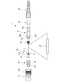
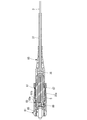
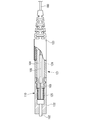
- FIG. 1 is an external perspective view of an embodiment of an optical connector according to the present invention. It is a disassembled side view which shows embodiment of the optical connector which concerns on this invention.
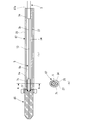
- (A) is a longitudinal cross-sectional view of the optical connector shown in FIG. 2,
- (b) is a principal part longitudinal cross-sectional view of the modification which attached the reinforcement tube.
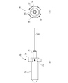
- (A) is the side view of an optical connector ferrule,
- (b) is the front view which looked at the optical connector ferrule from the short optical fiber side.
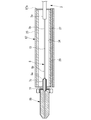
- FIG. (A) is a longitudinal cross-sectional view of the optical connector ferrule shown in FIG.
- FIG. 4 is a cross-sectional view of a protective sleeve connected to the optical connector ferrule.
- FIG. 7 is a longitudinal sectional view of the protective sleeve shown in FIG. 6 before a heat shrink process. It is a longitudinal cross-sectional view showing the structure of the modification in which the optical connector shown in FIG. 2 was applied to the core type. It is a principal part longitudinal cross-sectional view of the optical connector ferrule in which the adhesive agent was injected unevenly.
- FIGS. 4A to 4E are process diagrams for explaining an assembly procedure of the optical connector shown in FIG.
- FIGS. 5F to 5K are process diagrams for explaining an assembly procedure of the optical connector shown in FIG.
- (L)-(q) is process drawing explaining the assembly procedure of the optical connector shown in FIG. It is explanatory drawing of the structure which melt-connects the short optical fiber previously attached to the conventional optical connector ferrule, and an optical fiber core wire. It is explanatory drawing of the conventional optical connector.
- SYMBOLS 1 Optical connector, 3: Optical fiber core wire, 5: Short optical fiber, 7a: Tip axial part (ferrule main body), 7b: Diameter expansion part, 7c: Sleeve coupling protrusion (coupling protrusion), 7d: Optical fiber insertion hole 7e: hole, 7f: air escape hole, 7g: optical fiber guide part, 13: fusion splicing part, 25: heat shrinkable tube, 70: optical cord, 83: plug frame, 85: optical connector ferrule, 87: protection Sleeve, 95: Boots
- FIG. 1 is an external perspective view of an optical connector according to an embodiment of the present invention
- FIG. 2 is an exploded side view of the optical connector shown in FIG. 1
- FIG. 3A is a longitudinal sectional view of the optical connector shown in FIG. 3 (b) is a longitudinal sectional view of an essential part of a modified example equipped with a reinforcing tube
- FIG. 4 (a) is a side view of the optical connector ferrule
- FIG. 4 (b) is a view of the optical connector ferrule from the short optical fiber side
- FIG. 5 is a longitudinal sectional view of the optical connector ferrule.
- the optical connector 1 is attached to the end of the optical fiber core 3 exposed by removing a predetermined length of the outer sheath 72 (see FIG. 3) of the local optical cord 70.
- the plug frame 83 accommodates and holds the optical connector ferrule 85 to which the short optical fiber 5 is attached in advance.
- the protective sleeve 87 covers the outer periphery of the fusion splicing portion 13 (see FIG. 3) between the optical fiber core wire 3 and the short optical fiber 5 to protect the fusion splicing portion 13.
- the rear housing 91 has an internal space 17 in which the protective sleeve 87 is disposed, and the tip of the rear housing 91 is coupled to the plug frame 83 so as to be integrated with the plug frame 9.
- the boot 95 accommodates the vicinity of the end portion of the optical fiber core 3 fused and connected to the short optical fiber 5 to protect the optical fiber core 3, and the front end is coupled to the base end of the rear housing 91 to be integrated. Is done.
- the optical connector ferrule 85 is provided with an enlarged diameter portion 7b having an enlarged outer diameter behind the distal end shaft portion 7a that is butt-connected to the counterpart optical connector ferrule.
- the short optical fiber 5 is attached so that the distal end shaft portion 7a and the center axis coincide with each other in the shape thus formed.
- a sleeve coupling protrusion 7c for coupling a protective sleeve 87 projects from the outer periphery of the proximal end side of the optical connector ferrule 85 where the short optical fiber 5 is extended.
- the optical connector ferrule 85 has a tip shaft portion 7a of a zirconia ferrule serving as a ferrule main body fitted in a recess formed in the enlarged diameter portion 7b and coupled to the enlarged diameter portion 7b. It is integrated.
- the tip shaft portion (zirconia ferrule) 7a is formed with an optical fiber insertion hole 7d that is a fine hole through which the short optical fiber 5 is inserted and positioned.
- a hole 7e having an inner diameter larger than that of the optical fiber insertion hole 7d is formed so as to penetrate into the recess of the enlarged diameter portion 7b and communicate with the optical fiber insertion hole 7d.
- the enlarged diameter portion 7b of the optical connector ferrule 85 is formed with an air escape hole 7f that communicates the recess of the enlarged diameter portion 7b with the outside.
- the fiber introduction side of the optical fiber insertion hole 7d for inserting the short optical fiber 5 is an optical fiber guide portion 7g having a tapered surface in order to improve the insertion of the short optical fiber 5.
- a notch groove 7h used for preventing rotation of the ferrule main body and positioning during polishing is formed in the diameter-enlarging portion 7b on the opposite outer edge in the diameter direction.
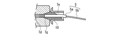
- the optical connector ferrule 85 is assembled by inserting the short optical fiber 5 from the rear end side of the optical connector ferrule 85 and stripping the exposed coating 5a on the front end side to expose the glass fiber portion 5b to the optical fiber insertion hole 7d. Place it inside. At that time, as shown in FIG. 5, the tip of the coating 5a (the boundary between the coating 5a and the glass fiber portion 5b) is set so as to be located in the optical fiber guide 7g, and the adhesive 10 is used. The short optical fiber 5 is bonded and fixed by being injected into the optical fiber insertion hole 7d and the optical fiber guide 7g. However, the adhesive 10 is not filled in the hole 7e of the sleeve coupling protrusion 7c and does not bond and fix the short optical fiber 5.
- the coating 5 a at the end of the short optical fiber 5 led out from the rear end of the optical connector ferrule 85 is peeled off, and the assembly is completed. That is, the short optical fiber 5 has the coating 5a at least in the hole 7e of the sleeve coupling protrusion 7c.
- the reduced diameter is such that the front end of the enlarged diameter portion 7b protrudes from the inner periphery of the plug frame 83 as shown in FIG.
- the forward movement is restricted.
- the position of the end of the optical connector ferrule 85 is regulated so as to protrude from the end of the plug frame 83 by a predetermined length L1.
- the tip of the optical connector ferrule 85 positioned on the plug frame 83 is attached with a dust cap 22 in order to prevent dust and the like from adhering to the fiber end face during storage. Is done.
- the illustration of the dust cap 22 is omitted except for FIG. Note that the tip surface of the optical connector ferrule 85 is mirror-polished in advance, so that on-site polishing is not required.
- a ferrule presser spring 89 is inserted in the plug frame 83 in which the optical connector ferrule 85 is inserted.
- the ferrule presser spring 89 is a compression coil spring that is sandwiched and held between the rear housing 91 that engages with the plug frame 83 and the enlarged diameter portion 7 b of the optical connector ferrule 85, and the enlarged diameter portion of the optical connector ferrule 85. 7b is brought into contact with the reduced diameter portion 9a of the plug frame 83 and at the same time elastically supported so as to be retractable.
- FIG. 6A is a longitudinal cross-sectional view of the optical connector ferrule shown in FIG. 5 and a protective sleeve connected to the optical connector ferrule
- FIG. 6B is a cross-sectional view taken along line AA in FIG.
- FIG. 7 is a longitudinal sectional view of the protective sleeve before the heat shrinking process.
- the outer diameter of the protective sleeve 87 is slightly exaggerated with respect to the optical connector ferrule 85 in order to clarify the heat shrinkage effect.
- the fusion splicing portion 13 is a fiber in which the portion 5b from which the coating 5a at the end of the short optical fiber 5 is stripped and the portion 3b from which the coating 3a from the end of the optical fiber core 3 is stripped are attached.
- the end surface of the short optical fiber 5 from which the coating 5a has been peeled is previously mirror-finished by cleaving by cutting the optical fiber by applying a bending stress or by polishing, thereby eliminating the need for on-site mirror finishing.
- the end face of the short optical fiber 5 is subjected to discharge treatment before the fusion splicing to drop the edge so that chipping from the edge caused by polishing can be prevented. Furthermore, since the short optical fiber 5 is transported to the site with the coating removed, it is preferable to use a carbon-coated fiber because strength reduction due to scratches and water absorption is suppressed. Moreover, it is preferable that the short optical fiber 5 is a fiber resistant to bending with a small MFD.
- the protective sleeve 87 includes a heat shrinkable tube 25, a mandrel 27 inserted through the heat shrinkable tube 25, and an adhesive tube 29 (see FIG. 7) through which an optical fiber is inserted.
- the contraction tube 25 is coupled onto the sleeve coupling protrusion 7 c of the optical connector ferrule 85.
- the optical fiber core 3 is mounted in the optical connector 1 with the outer sheath 72 at the end of the optical cord 70 removed by a predetermined length, and the protective sleeve 87 is on the other end side that is not coupled to the optical connector ferrule 85.
- the outer periphery of the optical fiber core wire 3 is covered.
- the heat-shrinkable tube 25 When the heat-shrinkable tube 25 is heated to a predetermined temperature by a heater, the heat-shrinkable tube 25 is heat-shrinked and comes into close contact with the inserted mandrel 27.
- the heat shrinkable tube 25 is heat shrunk to bring the mandrel 27 into close contact with the sleeve coupling protrusion 7 c of the optical connector ferrule 85 and also into close contact with the outer periphery of the optical fiber core wire 3.
- the air escape hole 7f is provided in the enlarged diameter portion 7b of the optical connector ferrule 85 as described above. Thereby, the air remaining inside the sleeve can be released to the outside through the air escape hole 7f via the hole 7e of the sleeve coupling protrusion 7c and the concave portion of the enlarged diameter portion 7b. Therefore, as shown in FIG. 5, an air flow path is intentionally secured in the hole 7e of the sleeve coupling protrusion 7c without being injected with an adhesive. Therefore, in the sleeve coupling protrusion 7c, the short optical fiber 5 in the non-bonded state is left without being stripped in order to ensure strength.
- the reason why the adhesive is not injected into the hole 7e of the sleeve coupling protrusion 7c is due to the following reason. That is, when assembling the optical contactor ferrule 85, when the hole 7e of the sleeve coupling protrusion 7c is filled with an adhesive and the inserted short optical fiber 5 is held, the injection of the adhesive is not strictly controlled. As shown in FIG. 9, the uneven shrinkage of the surroundings of the fiber is caused by uneven injection of the adhesive. It falls to the inner wall side where much adhesive is contained in the inner space of 7e. As a result, the short optical fiber 5 may cause bending loss.
- the characteristic configuration of the present invention is that the connector ferrule is formed by the adhesive 10 in which the short optical fiber 5 is filled only in the optical fiber insertion hole 7d and the optical fiber guide portion 7g of the connector ferrule 85. It is in the point held at 85. Thereby, the short optical fiber 5 does not fall down due to the difference in the curing shrinkage force of the adhesive in the inner space of the hole 7e, and even if it falls down and comes into contact with the inner wall surface of the hole 7e, the coating 5a Strength is secured.
- the adhesive tube 29 is softened by heating when the heat-shrinkable tube 25 is thermally contracted, and becomes an adhesive that fills the gap 34 between the heat-shrinkable tube 25 and the mandrel 27.
- the protective sleeve 87 positions the heat shrink tube 25, the mandrel 27, and the adhesive tube 29 at one end so that the end of the mandrel 27 and the end of the adhesive tube 29 coincide. In this positioning state, it is fixed to the sleeve coupling protrusion 7c of the optical connector ferrule 85.
- the optical connector ferrule 85 may be fixed and integrated with the heat shrinkable tube 25 and the end of the mandrel 27 by being press-fitted or welded without being bonded.
- the short optical fiber 5 is positioned so that the fusion splicing portion 13 is positioned at a substantially intermediate position in the longitudinal direction of the protective sleeve 87.
- the length dimensions of the heat shrinkable tube 25, the mandrel 27, and the adhesive tube 29 of the protective sleeve 87 are set.
- the rear housing 91 is a cylindrical structure that covers the periphery of the protective sleeve 87, and is formed by resin injection molding or the like.
- the distal end of the rear housing 91 is a cylindrical portion 91 a that is fitted into the proximal end of the plug frame 83.
- the cylindrical portion 91a is provided with a locking claw 91b that engages with a locking hole 83a formed on the outer periphery of the base end of the plug frame 83 when fitted into the base end of the plug frame 83. Yes.
- the rear housing 91 is moved and covered on the protective sleeve 87 after the heat shrinking process of the protective sleeve 87, and the engaging claw 91b on the distal end side is engaged with the engaging hole 83a of the plug frame 83.
- the plug frame 83 is combined and integrated.
- the outer periphery of the plug frame 83 to which the rear housing 91 is coupled is fitted with an SC connector knob 81 serving as a knob portion when the connector is connected.
- the SC connector knob 81 is an exterior member that provides the appearance of the distal end side of the optical connector 1, and has an anti-slip unevenness 33 a for facilitating gripping on the outer surface.
- the boot 95 may have a configuration in which a reinforcing tube 37 that covers the optical cord 70 is inserted and attached behind the end of the inner wall.
- the reinforcing tube 37 is provided with a retaining portion 37 a having an enlarged diameter at the tip, and the retaining portion 37 a is caught by the inner wall end in the boot 95, so that the movement is restricted.
- the reinforcing tube 37 is a tube having moderate elasticity and prevents the optical cord 70 from being bent suddenly.
- a direction alignment mark 97a is provided on the side surface of the enlarged diameter portion 7b of the optical connector ferrule 85.
- a direction alignment mark 97 b and a visual recognition groove 99 are provided on the side wall of the plug frame 83.
- the optical connector ferrule 85 is fitted to the plug frame 83 in a normal direction by matching the direction alignment mark 97a with the visual recognition groove 99 while confirming the direction alignment mark 97a.
- the optical connector 1 has a good work at the time of fusion splicing when the short optical fiber 5 of the optical connector ferrule 85 is fusion-bonded to the exposed optical fiber core wire 3 by removing the outer sheath 72 of the optical cord 70 in the field.
- the outer cover 72 at the end of the optical cord 70 is peeled off so that When the outer jacket 72 is peeled (removed) at the end of the optical cord 70, the optical fiber core wire 3 whose outer periphery is covered with a tensile strength fiber (Kevlar (registered trademark)) 74 is exposed.
- the tensile strength fiber 74 and the outer jacket 72 are cut into a predetermined length and are externally inserted into the rear end portion 91c of the rear housing 91.
- a caulking ring 93 is placed on the outer periphery of the outer sheath 72 that is inserted, and the caulking ring 93 is caulked in the diameter reducing direction.
- FIG. 8 is a longitudinal sectional view showing a configuration of a modification in which the optical connector shown in FIG. 2 is applied to a core type.
- the optical connector 1 according to this embodiment can also be used as a core type.
- the component configuration is the same except that the shape of the SC connector knob 81 is slightly different and the caulking ring 93 for fixing the tensile strength fiber 74 and the jacket 72 is not necessary.
- reference numeral 37 denotes a reinforcing tube for the optical fiber core wire 3.
- the optical connector 1 described above since one end of the protective sleeve 87 is coupled to the optical connector ferrule 85, positioning of the protective sleeve 87 becomes accurate regardless of the skill level of the operator. As a result, the overlap margin between the end portion of the protective sleeve 87 and the covering portion of the optical fiber core wire 3 can be reduced to about 3 mm, thereby greatly reducing the length of the protective sleeve 87 and increasing the length of the optical connector 1. Can be made compact. Therefore, the compactness of the optical connector 1 can increase the accommodation capacity in a small aerial closure or the like.
- the protective sleeve 87 covering the periphery of the short optical fiber 5 and the fusion splicing portion 13 is coupled to the optical connector ferrule 85, and the optical connector ferrule 85 is brought into contact with the other optical connector ferrule when the connector is connected. Is retracted, the protective sleeve 87 is also retracted integrally with the optical connector ferrule 85, so that a large compressive load is not applied to the short optical fiber 5. Therefore, a large bending load is prevented from acting on the short optical fiber 5 attached to the optical connector ferrule 85 during connector connection work, and problems such as an increase in the bending loss and breakage of the optical fiber are avoided. You can also.
- the protective sleeve 87 includes the heat shrinkable tube 25, the mandrel 27 and the adhesive tube 29 inserted through the heat shrinkable tube 25, and the protective sleeve 87 is coupled to the optical connector ferrule 85. It has a configuration.
- the protective sleeve 87 is connected to the sleeve coupling protrusion 7c of the optical connector ferrule 85 at one end, and then the heat shrinkable tube 25 around the outer periphery is heat shrunk by a heat treatment by a heating machine.
- the fusion splicing portion 13 between the optical fiber 5 and the local optical fiber core wire 3 can be securely held in a state of being vertically attached to the mandrel 27, and the fusion splicing portion 13 can be reinforced firmly. That is, the fusion splicing portion 13 can be protected by the protective sleeve 87 easily and reliably even at a site where it is difficult to prepare work facilities and the like.
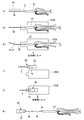
- FIGS. 10A to 10E are process diagrams for explaining the assembly procedure of the optical connector shown in FIG. 2
- FIGS. 11F to 11K are steps for explaining the assembly procedure of the optical connector shown in FIG.
- FIGS. 12 (l) to 12 (q) are process diagrams for explaining the assembly procedure of the optical connector shown in FIG.
- the outer jacket 72 on the tip side of the optical cord 70 is removed, and the extra tensile strength fiber 74 is cut.
- a slit 103 in the axial direction is made in the outer cover 72 and is broken.
- the outer jacket 72 and the exposed tensile strength fiber 74 are folded back so as not to interfere with the subsequent work.
- the protective sleeve 87 is inserted through the optical fiber core wire 3.
- the optical fiber core wire 3 drawn out from the protective sleeve 87 removes the coating 3 a to expose the glass fiber portion 3 b and then cleans the portion 3 b.
- the protective sleeve 87 and the optical fiber core wire 3 are set in the fusion fiber holder 105A. After the mirror surface is cut to a predetermined length as shown in FIG. 11 (h), the protective sleeve 87 and the optical fiber core wire 3 are set in a fusion machine (not shown).
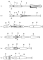
- the optical connector ferrule 85 containing the short optical fiber 5 is set in the ferrule holder 105B.
- reference numeral 22 denotes a dust cap.
- the ferrule holder 105B holding the optical connector ferrule 85 is set in a fusion machine (not shown).
- the tip of the protective sleeve 87 is inserted into the sleeve coupling protrusion 7c of the optical connector ferrule 85 to cover the fusion splicing portion 13, and the protective sleeve 87 is heated and shrunk.
- the tensile strength fiber 74 and the jacket 72 that have been folded back are returned.
- the dust cap 22 is removed from the optical connector ferrule 85, the plug frame 83 is inserted from the front end side of the optical connector ferrule 85, and the rear housing 91 is plugged into the plug frame while accommodating the ferrule presser spring 89. Assemble to 83. As shown in FIG. 12 (o), the tensile strength fiber 74 and the outer jacket 72 are placed on the rear end portion 91 c of the rear housing 91.
- the caulking ring 93 is crimped to fix the tensile strength fiber 74 and the jacket 72 to the rear end 91c.
- the SC connector knob 81 and the boot 95 are coupled to the plug frame 83 and the rear housing 91, respectively, to complete the assembly of the optical connector 1.
Landscapes
- Physics & Mathematics (AREA)
- General Physics & Mathematics (AREA)
- Optics & Photonics (AREA)
- Engineering & Computer Science (AREA)
- Plasma & Fusion (AREA)
- Mechanical Coupling Of Light Guides (AREA)
Abstract
Description
特許文献1に示された光コネクタ110は、予め光コネクタフェルール102に取り付けられた短尺光ファイバ103と、現地の光ファイバ心線100とが融着接続により接続され、その融着接続部105の周囲が保護スリーブ101で覆われて補強されている。
そして、コネクタハウジング121は、光コネクタフェルール102から保護スリーブ101の後方の光ファイバ心線100の一部までを内部に収容する構成となっている。
また、コネクタハウジング121は、光コネクタフェルール102の先端を突出させた状態に収容したプラグフレーム122と、光ファイバ心線100の端部を収容したブーツ123と、一端がプラグフレーム122に嵌合され一体化すると共に他端がブーツ123に嵌合され一体化する筒状のストップリング124とを備えている。プラグフレーム122内の光コネクタフェルール102は、圧縮コイルばね125により先端側に付勢されている。この圧縮コイルばね125は、コネクタ接続時に、光コネクタフェルール102の後退を許容し、当該光コネクタフェルール102と相手側光コネクタの光コネクタフェルールとの接触圧を規定範囲に保つ。
なお、光コネクタ110の長大化を阻止するために、保護スリーブ101の長さ寸法を短くすることも考えられるが、この場合、作業者の熟練差又は誤操作等で保護スリーブ101の固定位置が軸方向に位置ずれして、裸の光ファイバが露出してしまう虞があり、各光ファイバ心線の被覆部への重ね代をそれほど短縮することができない。
従って、保護スリーブ101の短縮等には効果が小さく、キャビネット等への収容が難しいという課題は残ったままであった。
従って、光コネクタのコンパクト化により、小型キャビネット等への収容性を高めることができる。
従って、保護スリーブ内の気泡の残存によって、光ファイバに曲げ応力を発生させることがない。
図1は本発明に係る光コネクタの一実施形態の外観斜視図、図2は図1に示した光コネクタの分解側面図、図3(a)は図1に示した光コネクタの縦断面図、図3(b)は補強チューブを装着した変形例の要部縦断面図、図4(a)は光コネクタフェルールの側面図、図4(b)は光コネクタフェルールを短尺光ファイバ側から見た正面図、図5は光コネクタフェルールの縦断面図である。
この実施形態の光コネクタは、光コード70を接続するコード型、光ファイバ心線3を接続する心線型の双方に適用することができる。心線型光コネクタは、後述するSCコネクタつまみの形状がやや異なる他はコード型光コネクタと略共通の部品が用いられる。以下の説明では主にコード型光コネクタ(単に「光コネクタ」とも称す)1について説明する。
なお、光コネクタフェルール85の先端面は予め鏡面研磨されていて、現地での研磨加工が不要になされている。
融着接続部13は、短尺光ファイバ5の端部の被覆5aを剥いだ部分5bと、光ファイバ心線3の端部の被覆3aを剥いだ部分3bとを付き合わせて、付き合わせたファイバ端面同士を融着させることにより形成される。
なお、被覆5aを剥いだ短尺光ファイバ5の端面は、予め、光ファイバに曲げ応力をかけて切断する劈開により、あるいは、研磨によって鏡面加工され、現地での鏡面加工を不要にしている。
熱収縮チューブ25を熱収縮させた時、軸線方向の両端(光コネクタフェルール85と光ファイバ心線3にそれぞれ密着する部位)が中央部より速く収縮すると、空気が保護スリーブ87内及びスリーブ結合突起7c内に閉じ込められて気泡が発生する。
なお、接着チューブ29は、熱収縮チューブ25を熱収縮させる際の加熱で軟化して、熱収縮チューブ25と心棒27との間の隙間34を埋める接着剤となる。
光コネクタフェルール85は、熱収縮チューブ25及び心棒27の端部が、接着によらず、圧入又は溶着されることにより、これらに固定され一体化されていても良い。
このように、熱収縮チューブ25を熱収縮させた時、熱収縮チューブ25の端部が、光ファイバ心線3の被覆3a及びスリーブ結合突起7cの上に2mm以上重なるように、各部品の寸法が設定されている。
このリアハウジング91は、保護スリーブ87の熱収縮処理後に、保護スリーブ87の上に移動して被せられ、先端側の係止爪91bをプラグフレーム83の係止穴83aに係合させることにより、プラグフレーム83に結合されて一体化される。
但し、樹脂の射出成形により、リアハウジング91と一体形成するようにしても良い。
なお、ブーツ95は、図3(b)に示すように、内壁端の後方に、光コード70に被せられる補強チューブ37が挿入され装着される構成であっても良い。
補強チューブ37は、先端に拡径した抜け止め部37aが設けられており、抜け止め部37aがブーツ95内の内壁端に引っかかることで、移動が規制される。補強チューブ37は適度な弾性を有したチューブで光コード70が急激に曲げられることを防止する。
既述したように本実施の形態による光コネクタ1は、心線型としても用いることができる。この場合、その部品構成は、SCコネクタつまみ81の形状が若干異なる点、抗張力繊維74、外被72を固定するためのかしめリング93が不要となる点のみで他は同一である。なお、図8中、37は光ファイバ心線3用の補強チューブを示す。
従って、光コネクタ1のコンパクト化により、小型の架空クロージャ等への収容性を高めることができる。
従って、コネクタ接続作業の際に、光コネクタフェルール85に取り付けられた短尺光ファイバ5に大きな曲げ荷重が作用することを防止して、光ファイバの曲げ損失の増加や破損等の問題を回避することもできる。
即ち、作業設備等を整え難い現地でも、簡単且つ確実に、保護スリーブ87により融着接続部13を保護することができる。
図10(a)~(e)は図2に示した光コネクタの組立手順を説明する工程図、図11(f)~(k)は図2に示した光コネクタの組立手順を説明する工程図、図12(l)~(q)は図2に示した光コネクタの組立手順を説明する工程図である。
光コネクタ1を組立てるには、先ず、図10(a)に示すように、現地の光コード70の端部に、ブーツ95、かしめリング93、リアハウジング91、フェルール押えばね89の順番に当該各部を挿入しておく。
Claims (3)
- 光コネクタフェルールに取り付けられた短尺光ファイバと光ファイバ心線とを融着接続した融着接続部を収容して保持する光コネクタであって、
前記短尺光ファイバと前記光ファイバ心線を挿通して前記融着接続部の周囲を覆う熱収縮材からなる保護スリーブの一端が前記光コネクタフェルールに結合されており、前記光コネクタフェルールには前記保護スリーブの内部と連通する空気逃し穴が設けられていることを特徴とする光コネクタ。 - 前記短尺光ファイバは、被覆を剥いだ先端部分が前記光コネクタフェルールの光ファイバ挿通孔に挿入されると共に、前記先端部分及び前記被覆との境界部が前記光ファイバ挿通孔に接着固定されることを特徴とする請求項1に記載の光コネクタ。
- 前記光コネクタフェルールは、フェルール本体と、前記フェルール本体と結合して一体化する拡径部と、前記拡径部の一端に連接して前記保護スリーブが外嵌される結合突起とを備え、
前記短尺光ファイバは、被覆を剥いだ先端部分及び前記融着接続部で除去される被覆が少なくとも前記結合突起内で残されていることを特徴とする請求項1又は2に記載の光コネクタ。
Priority Applications (5)
| Application Number | Priority Date | Filing Date | Title |
|---|---|---|---|
| CN2008801276967A CN101978300B (zh) | 2008-02-29 | 2008-12-17 | 光纤连接器 |
| BRPI0822327-0A BRPI0822327B1 (pt) | 2008-02-29 | 2008-12-17 | Conector óptico para alojar e reter uma porção emendada por fusão |
| US12/920,060 US8317406B2 (en) | 2008-02-29 | 2008-12-17 | Optical connector |
| ES08872849.8T ES2643028T3 (es) | 2008-02-29 | 2008-12-17 | Conector óptico |
| EP08872849.8A EP2249189B1 (en) | 2008-02-29 | 2008-12-17 | Optical connector |
Applications Claiming Priority (2)
| Application Number | Priority Date | Filing Date | Title |
|---|---|---|---|
| JP2008-050009 | 2008-02-29 | ||
| JP2008050009A JP4719755B2 (ja) | 2008-02-29 | 2008-02-29 | 光コネクタ |
Publications (1)
| Publication Number | Publication Date |
|---|---|
| WO2009107306A1 true WO2009107306A1 (ja) | 2009-09-03 |
Family
ID=41015713
Family Applications (1)
| Application Number | Title | Priority Date | Filing Date |
|---|---|---|---|
| PCT/JP2008/073019 Ceased WO2009107306A1 (ja) | 2008-02-29 | 2008-12-17 | 光コネクタ |
Country Status (8)
| Country | Link |
|---|---|
| US (1) | US8317406B2 (ja) |
| EP (1) | EP2249189B1 (ja) |
| JP (1) | JP4719755B2 (ja) |
| CN (1) | CN101978300B (ja) |
| BR (1) | BRPI0822327B1 (ja) |
| ES (1) | ES2643028T3 (ja) |
| TW (1) | TWI427344B (ja) |
| WO (1) | WO2009107306A1 (ja) |
Cited By (4)
| Publication number | Priority date | Publication date | Assignee | Title |
|---|---|---|---|---|
| WO2012041840A1 (de) | 2010-10-01 | 2012-04-05 | Huber+Suhner Ag | Steckverbinder |
| WO2012090570A1 (ja) * | 2010-12-28 | 2012-07-05 | Seiオプティフロンティア株式会社 | 光コネクタおよび光コネクタの組み立て方法 |
| CN102576133A (zh) * | 2009-10-28 | 2012-07-11 | Sei光学前沿株式会社 | 光学连接器 |
| WO2025053090A1 (ja) * | 2023-09-08 | 2025-03-13 | 住友電工オプティフロンティア株式会社 | 融着スリーブおよび光コネクタの製造方法 |
Families Citing this family (42)
| Publication number | Priority date | Publication date | Assignee | Title |
|---|---|---|---|---|
| JP5460347B2 (ja) * | 2010-01-19 | 2014-04-02 | 古河電気工業株式会社 | 光ファイバ用補強スリーブ |
| JP5398560B2 (ja) * | 2010-01-25 | 2014-01-29 | 株式会社フジクラ | 光コネクタ及びその組立方法 |
| KR101038195B1 (ko) * | 2010-07-08 | 2011-06-01 | 박찬설 | 광섬유 커넥터와 이의 조립방법 |
| JP5759183B2 (ja) * | 2011-01-14 | 2015-08-05 | Seiオプティフロンティア株式会社 | 光コネクタ及びその組立方法 |
| RU2640096C2 (ru) | 2011-02-17 | 2017-12-26 | Тайко Электроникс Райхем Бвба | Портативное устройство для прикрепления разъема к оптическому волокну |
| CN102866467A (zh) * | 2011-07-05 | 2013-01-09 | 朴撰卨 | 光纤连接器 |
| CN102289037B (zh) * | 2011-08-29 | 2013-01-16 | 深圳市特发信息光网科技股份有限公司 | 光纤现场热熔快速连接器 |
| KR101203509B1 (ko) | 2011-11-21 | 2012-11-21 | 박찬설 | 광섬유 커넥터 |
| WO2013077969A1 (en) * | 2011-11-23 | 2013-05-30 | Adc Telecommunications, Inc. | Multi-fiber fiber optic connector |
| JP2013114001A (ja) * | 2011-11-28 | 2013-06-10 | Fujikura Ltd | コネクタ付き光ファイバケーブル、コネクタ付き光ファイバケーブルの組立方法 |
| CN103781397B (zh) * | 2012-06-28 | 2016-08-17 | 奥林巴斯株式会社 | 扫描型内窥镜和扫描型内窥镜的制造方法 |
| CN103576246B (zh) * | 2012-08-03 | 2015-06-10 | 鸿富锦精密工业(深圳)有限公司 | 光纤连接器 |
| US8939654B2 (en) * | 2012-09-27 | 2015-01-27 | Adc Telecommunications, Inc. | Ruggedized multi-fiber fiber optic connector with sealed dust cap |
| CN102928923B (zh) * | 2012-11-01 | 2014-01-29 | 南京普天天纪楼宇智能有限公司 | 一种热熔型现场组装式光纤连接器 |
| CN102928922B (zh) * | 2012-11-01 | 2014-01-29 | 南京普天天纪楼宇智能有限公司 | 一种热熔型光纤快速连接器 |
| JP6082599B2 (ja) * | 2013-01-11 | 2017-02-15 | 古河電気工業株式会社 | 光コネクタ、光コネクタの製造方法 |
| US9411110B2 (en) * | 2013-02-06 | 2016-08-09 | Corning Optical Communications LLC | Fiber optic connector cover and fiber optic assembly including same |
| BR112015024236A2 (pt) | 2013-03-21 | 2017-07-18 | 3M Innovative Properties Co | conector óptico para cabos encapados |
| JP5937141B2 (ja) | 2013-05-29 | 2016-06-22 | 住友電気工業株式会社 | 光干渉断層撮影装置用カテーテルの製造方法、および光干渉断層撮影装置用カテーテル |
| US9829647B2 (en) | 2013-07-22 | 2017-11-28 | Commscope Technologies Llc | Expanded beam fiber optic connector, and cable assembly, and methods for manufacturing |
| WO2015013264A1 (en) | 2013-07-22 | 2015-01-29 | Adc Telecommunications, Inc. | Fiber optic cable and connector assembly including integrated enhanced functionality |
| CN103616746B (zh) * | 2013-12-04 | 2015-04-29 | 中国联合网络通信有限公司北京市分公司 | 一种用于在fc光纤连接器上安装电子标签的装置 |
| WO2015095872A1 (en) | 2013-12-20 | 2015-06-25 | Afl Telecommunications Llc | Splice-on optical connector for outside plant drop cable |
| AU2015320164B2 (en) | 2014-09-26 | 2021-03-04 | Adc Telecommunications (Shanghai) Distribution Co., Ltd. | Optical fiber connector and assembly method therefor |
| ES1137083Y (es) * | 2015-02-17 | 2015-05-25 | Telefonica Sa | Dispositivo conector óptico de montaje en campo exterior |
| CN104965262B (zh) * | 2015-06-17 | 2017-05-03 | 深圳日海通讯技术股份有限公司 | 光纤连接器及其光纤连接器的制造方法 |
| CN105372765B (zh) * | 2015-07-31 | 2018-01-16 | 中航光电科技股份有限公司 | 光纤连接器 |
| JP6159429B1 (ja) * | 2016-01-18 | 2017-07-05 | 株式会社フジクラ | 光コネクタ、及び、光コネクタの製造方法 |
| TWI669548B (zh) * | 2016-08-01 | 2019-08-21 | 偉電科技股份有限公司 | Multi-core SC connector and socket |
| JP6968110B2 (ja) * | 2017-02-10 | 2021-11-17 | 富士フイルム株式会社 | 光コネクタおよび光音響波発生装置 |
| JP2019066724A (ja) * | 2017-10-03 | 2019-04-25 | 株式会社フジクラ | コネクタ付きケーブル及びコネクタ製造方法 |
| US12461318B2 (en) | 2019-07-17 | 2025-11-04 | Commscope Technologies Llc | Fiber optic connector with overmold lead-in tube |
| EP3999890A4 (en) | 2019-07-17 | 2023-08-16 | CommScope Technologies LLC | FIBER OPTIC CONNECTOR WITH ANTI-CAPILLARY EPOXY TUBE |
| US11846811B2 (en) | 2019-07-17 | 2023-12-19 | Commscope Technologies Llc | Tuned fiber optic connector |
| MX2022000546A (es) * | 2019-07-17 | 2022-02-10 | Commscope Technologies Llc | Conector de fibra optica con tubo de epoxi con flotador axial. |
| KR102326928B1 (ko) * | 2019-09-25 | 2021-11-16 | 유씨엘 주식회사 | 옥외용 현장조립 방수 광커넥터 플러그 및 이의 현장조립과정 |
| WO2021084982A1 (ja) * | 2019-11-01 | 2021-05-06 | 株式会社フジクラ | 融着型光コネクタ付き配線、融着型光コネクタ付き配線の製造方法 |
| US12523821B2 (en) | 2021-04-08 | 2026-01-13 | Commscope Technologies Llc | Telecommunications connector with latch release mechanism |
| US12416766B2 (en) | 2022-11-01 | 2025-09-16 | Panduit Corp. | Fusion spliced connector |
| WO2025053088A1 (ja) | 2023-09-08 | 2025-03-13 | 住友電工オプティフロンティア株式会社 | 光コネクタおよびピンキーパ |
| WO2025053077A1 (ja) * | 2023-09-08 | 2025-03-13 | 住友電工オプティフロンティア株式会社 | 光ファイバホルダ、スタブホルダ、および融着接続機 |
| JP2025153166A (ja) * | 2024-03-29 | 2025-10-10 | 住友電工オプティフロンティア株式会社 | 光コネクタおよび光コネクタの取り付け方法 |
Citations (6)
| Publication number | Priority date | Publication date | Assignee | Title |
|---|---|---|---|---|
| JPH01216303A (ja) * | 1988-02-24 | 1989-08-30 | Nippon Telegr & Teleph Corp <Ntt> | 光コネクタ用フェルール |
| JPH06337325A (ja) * | 1993-05-28 | 1994-12-06 | Nec Corp | 光ファイバコネクタ用フェルール構造 |
| JP2001013355A (ja) * | 1999-06-29 | 2001-01-19 | Sumitomo Electric Ind Ltd | 光ファイバ融着接続部の保護部材加熱装置及び加熱方法 |
| JP2002082257A (ja) * | 2000-09-06 | 2002-03-22 | Sumitomo Electric Ind Ltd | 光コネクタおよび光コネクタ部品 |
| JP2008181026A (ja) * | 2007-01-25 | 2008-08-07 | Sumitomo Electric Ind Ltd | 光ファイバの保護スリーブ |
| JP2008225461A (ja) * | 2007-02-09 | 2008-09-25 | Fujikura Ltd | コネクタ付き光ファイバケーブルおよび光コネクタ、ならびに光コネクタの組立方法 |
Family Cites Families (10)
| Publication number | Priority date | Publication date | Assignee | Title |
|---|---|---|---|---|
| JPS6418113A (en) * | 1987-07-13 | 1989-01-20 | Nippon Telegraph & Telephone | Method and device for assembling optical connector |
| US5201019A (en) * | 1991-07-15 | 1993-04-06 | Amphenol Corporation | Fiber optic splice connection and a method of making same |
| CA2226052A1 (en) * | 1997-02-13 | 1998-08-13 | Diamond Sa | Plug for an optical fiber plug connector and method of its manufacture |
| EP0939327A3 (de) * | 1998-02-27 | 2002-02-13 | Siemens Aktiengesellschaft | Steckeranschluss für Lichtwellenleiter und Verfahren zu dessen Herstellung |
| JP3765688B2 (ja) * | 1999-06-16 | 2006-04-12 | 富士通株式会社 | 光ファイバ接続機構、光ファイバ構造体及び光ファイバ接続方法 |
| DE19933740C2 (de) * | 1999-07-19 | 2003-10-30 | Ccs Technology Inc | Lichtwellenleiterstecker und Verfahren zum Anschluß an das Ende eines Lichtwellenleiters |
| US7329049B2 (en) * | 2005-12-27 | 2008-02-12 | Corning Cable Systems Llc | Splice connector for verifying an acceptable splice termination |
| US7264410B1 (en) * | 2006-03-16 | 2007-09-04 | Corning Cable Systems Llc | Dual function splice component for mechanical splice connector |
| US7934874B2 (en) * | 2006-11-13 | 2011-05-03 | Sumitomo Electric Industries, Ltd. | Holder, fusion-splicing apparatus, and manufacturing method of optical connector |
| JP5184865B2 (ja) * | 2006-11-13 | 2013-04-17 | 住友電気工業株式会社 | 光コネクタ |
-
2008
- 2008-02-29 JP JP2008050009A patent/JP4719755B2/ja active Active
- 2008-12-17 US US12/920,060 patent/US8317406B2/en active Active
- 2008-12-17 EP EP08872849.8A patent/EP2249189B1/en active Active
- 2008-12-17 ES ES08872849.8T patent/ES2643028T3/es active Active
- 2008-12-17 CN CN2008801276967A patent/CN101978300B/zh active Active
- 2008-12-17 BR BRPI0822327-0A patent/BRPI0822327B1/pt active IP Right Grant
- 2008-12-17 WO PCT/JP2008/073019 patent/WO2009107306A1/ja not_active Ceased
-
2009
- 2009-01-22 TW TW098102622A patent/TWI427344B/zh active
Patent Citations (6)
| Publication number | Priority date | Publication date | Assignee | Title |
|---|---|---|---|---|
| JPH01216303A (ja) * | 1988-02-24 | 1989-08-30 | Nippon Telegr & Teleph Corp <Ntt> | 光コネクタ用フェルール |
| JPH06337325A (ja) * | 1993-05-28 | 1994-12-06 | Nec Corp | 光ファイバコネクタ用フェルール構造 |
| JP2001013355A (ja) * | 1999-06-29 | 2001-01-19 | Sumitomo Electric Ind Ltd | 光ファイバ融着接続部の保護部材加熱装置及び加熱方法 |
| JP2002082257A (ja) * | 2000-09-06 | 2002-03-22 | Sumitomo Electric Ind Ltd | 光コネクタおよび光コネクタ部品 |
| JP2008181026A (ja) * | 2007-01-25 | 2008-08-07 | Sumitomo Electric Ind Ltd | 光ファイバの保護スリーブ |
| JP2008225461A (ja) * | 2007-02-09 | 2008-09-25 | Fujikura Ltd | コネクタ付き光ファイバケーブルおよび光コネクタ、ならびに光コネクタの組立方法 |
Non-Patent Citations (1)
| Title |
|---|
| See also references of EP2249189A4 * |
Cited By (12)
| Publication number | Priority date | Publication date | Assignee | Title |
|---|---|---|---|---|
| CN102576133A (zh) * | 2009-10-28 | 2012-07-11 | Sei光学前沿株式会社 | 光学连接器 |
| US8690454B2 (en) | 2009-10-28 | 2014-04-08 | Sei Optifrontier Co., Ltd. | Optical connector |
| CN102576133B (zh) * | 2009-10-28 | 2014-06-04 | Sei光学前沿株式会社 | 光学连接器 |
| WO2012041840A1 (de) | 2010-10-01 | 2012-04-05 | Huber+Suhner Ag | Steckverbinder |
| CN103124916A (zh) * | 2010-10-01 | 2013-05-29 | 胡贝尔和茹纳股份公司 | 插入式连接器 |
| US20130183007A1 (en) * | 2010-10-01 | 2013-07-18 | Nesa Scopic | Plug-in connector |
| US8931963B2 (en) | 2010-10-01 | 2015-01-13 | Huber+Suhner Ag | Plug-in connector |
| CN103124916B (zh) * | 2010-10-01 | 2015-06-17 | 胡贝尔和茹纳股份公司 | 插入式连接器 |
| WO2012090570A1 (ja) * | 2010-12-28 | 2012-07-05 | Seiオプティフロンティア株式会社 | 光コネクタおよび光コネクタの組み立て方法 |
| JP2012141437A (ja) * | 2010-12-28 | 2012-07-26 | Sei Optifrontier Co Ltd | 光コネクタ及び光コネクタの組立方法 |
| US9110253B2 (en) | 2010-12-28 | 2015-08-18 | Sei Optifrontier Co., Ltd. | Optical connector and method for assembling optical connector |
| WO2025053090A1 (ja) * | 2023-09-08 | 2025-03-13 | 住友電工オプティフロンティア株式会社 | 融着スリーブおよび光コネクタの製造方法 |
Also Published As
| Publication number | Publication date |
|---|---|
| BRPI0822327A2 (pt) | 2015-06-16 |
| CN101978300A (zh) | 2011-02-16 |
| TW200944855A (en) | 2009-11-01 |
| US8317406B2 (en) | 2012-11-27 |
| ES2643028T3 (es) | 2017-11-21 |
| EP2249189B1 (en) | 2017-08-16 |
| JP2009205100A (ja) | 2009-09-10 |
| CN101978300B (zh) | 2013-04-17 |
| US20110008003A1 (en) | 2011-01-13 |
| JP4719755B2 (ja) | 2011-07-06 |
| EP2249189A4 (en) | 2014-12-17 |
| EP2249189A1 (en) | 2010-11-10 |
| BRPI0822327B1 (pt) | 2021-09-14 |
| TWI427344B (zh) | 2014-02-21 |
Similar Documents
| Publication | Publication Date | Title |
|---|---|---|
| JP4719755B2 (ja) | 光コネクタ | |
| JP5192094B2 (ja) | 光コネクタ | |
| JP5277962B2 (ja) | ホルダ及び融着接続機及び光コネクタの組立方法 | |
| JP5806305B2 (ja) | 光ファイバコネクター及びその組立方法 | |
| JP5759183B2 (ja) | 光コネクタ及びその組立方法 | |
| CN101535857B (zh) | 光纤连接器 | |
| WO2011052634A1 (ja) | 光コネクタの組立方法 | |
| WO2022049792A1 (ja) | 光コネクタ及び光コネクタ製造方法 |
Legal Events
| Date | Code | Title | Description |
|---|---|---|---|
| WWE | Wipo information: entry into national phase |
Ref document number: 200880127696.7 Country of ref document: CN |
|
| 121 | Ep: the epo has been informed by wipo that ep was designated in this application |
Ref document number: 08872849 Country of ref document: EP Kind code of ref document: A1 |
|
| REEP | Request for entry into the european phase |
Ref document number: 2008872849 Country of ref document: EP |
|
| WWE | Wipo information: entry into national phase |
Ref document number: 12920060 Country of ref document: US Ref document number: 2008872849 Country of ref document: EP |
|
| NENP | Non-entry into the national phase |
Ref country code: DE |
|
| ENP | Entry into the national phase |
Ref document number: PI0822327 Country of ref document: BR Kind code of ref document: A2 Effective date: 20100827 |