WO2009107418A1 - タービンディスク及びガスタービン - Google Patents
タービンディスク及びガスタービン Download PDFInfo
- Publication number
- WO2009107418A1 WO2009107418A1 PCT/JP2009/050551 JP2009050551W WO2009107418A1 WO 2009107418 A1 WO2009107418 A1 WO 2009107418A1 JP 2009050551 W JP2009050551 W JP 2009050551W WO 2009107418 A1 WO2009107418 A1 WO 2009107418A1
- Authority
- WO
- WIPO (PCT)
- Prior art keywords
- cooling
- turbine
- turbine disk
- circumferential direction
- cooling hole
- Prior art date
- Legal status (The legal status is an assumption and is not a legal conclusion. Google has not performed a legal analysis and makes no representation as to the accuracy of the status listed.)
- Ceased
Links
Images


Classifications
-
- F—MECHANICAL ENGINEERING; LIGHTING; HEATING; WEAPONS; BLASTING
- F01—MACHINES OR ENGINES IN GENERAL; ENGINE PLANTS IN GENERAL; STEAM ENGINES
- F01D—NON-POSITIVE DISPLACEMENT MACHINES OR ENGINES, e.g. STEAM TURBINES
- F01D5/00—Blades; Blade-carrying members; Heating, heat-insulating, cooling or antivibration means on the blades or the members
- F01D5/02—Blade-carrying members, e.g. rotors
- F01D5/08—Heating, heat-insulating or cooling means
- F01D5/085—Heating, heat-insulating or cooling means cooling fluid circulating inside the rotor
- F01D5/087—Heating, heat-insulating or cooling means cooling fluid circulating inside the rotor in the radial passages of the rotor disc
-
- F—MECHANICAL ENGINEERING; LIGHTING; HEATING; WEAPONS; BLASTING
- F01—MACHINES OR ENGINES IN GENERAL; ENGINE PLANTS IN GENERAL; STEAM ENGINES
- F01D—NON-POSITIVE DISPLACEMENT MACHINES OR ENGINES, e.g. STEAM TURBINES
- F01D5/00—Blades; Blade-carrying members; Heating, heat-insulating, cooling or antivibration means on the blades or the members
- F01D5/02—Blade-carrying members, e.g. rotors
- F01D5/08—Heating, heat-insulating or cooling means
- F01D5/081—Cooling fluid being directed on the side of the rotor disc or at the roots of the blades
-
- F—MECHANICAL ENGINEERING; LIGHTING; HEATING; WEAPONS; BLASTING
- F01—MACHINES OR ENGINES IN GENERAL; ENGINE PLANTS IN GENERAL; STEAM ENGINES
- F01D—NON-POSITIVE DISPLACEMENT MACHINES OR ENGINES, e.g. STEAM TURBINES
- F01D5/00—Blades; Blade-carrying members; Heating, heat-insulating, cooling or antivibration means on the blades or the members
- F01D5/30—Fixing blades to rotors; Blade roots ; Blade spacers
- F01D5/32—Locking, e.g. by final locking blades or keys
- F01D5/323—Locking of axial insertion type blades by means of a key or the like parallel to the axis of the rotor
-
- F—MECHANICAL ENGINEERING; LIGHTING; HEATING; WEAPONS; BLASTING
- F05—INDEXING SCHEMES RELATING TO ENGINES OR PUMPS IN VARIOUS SUBCLASSES OF CLASSES F01-F04
- F05D—INDEXING SCHEME FOR ASPECTS RELATING TO NON-POSITIVE-DISPLACEMENT MACHINES OR ENGINES, GAS-TURBINES OR JET-PROPULSION PLANTS
- F05D2260/00—Function
- F05D2260/94—Functionality given by mechanical stress related aspects such as low cycle fatigue [LCF] of high cycle fatigue [HCF]
- F05D2260/941—Functionality given by mechanical stress related aspects such as low cycle fatigue [LCF] of high cycle fatigue [HCF] particularly aimed at mechanical or thermal stress reduction
Definitions
- the present invention provides, for example, a gas turbine that supplies fuel to compressed high-temperature and high-pressure air to burn, and supplies the generated combustion gas to the turbine to obtain rotational power.
- the present invention relates to a turbine disk provided with a plurality of rotor blades, and a gas turbine having the turbine disk.
- the gas turbine is composed of a compressor, a combustor, and a turbine.
- the air taken in from the air intake port is compressed by the compressor to become high-temperature and high-pressure compressed air.
- fuel is supplied to the compressed air and burned.
- High-temperature and high-pressure combustion gas drives the turbine, and drives a generator connected to the turbine.
- the turbine is configured by alternately arranging a plurality of stationary blades and moving blades in a vehicle interior, and drives the moving blades with combustion gas to rotationally drive the output shaft connected to the generator.
- the combustion gas that has driven the turbine is converted to static pressure by the diffuser in the exhaust casing and then released to the atmosphere.
- a cooling passage is formed inside the stationary blade and the moving blade, and a cooling medium such as air or steam is allowed to flow through the cooling passage, thereby cooling the stationary blade and the moving blade to improve heat resistance.
- the combustion gas is heated to increase the output and efficiency.
- a plurality of moving blade bodies having cooling passages formed therein are fixed side by side in the circumferential direction on the outer peripheral portion of the turbine disk.
- a cooling hole is formed along the radial direction, and the tip of the cooling hole communicates with the cooling passage of the rotor blade body. Then, a cooling medium is supplied from the base end portion to the cooling hole, and flows into the cooling passage through the cooling hole to cool the rotor blade body.
- a plurality of moving blades receive combustion gas and rotate at a high speed, and therefore, tensile stress acts by centrifugal force.
- the turbine disk has the same number of cooling holes as the rotor blade body, the tensile stress acting on the turbine disk is concentrated near the cooling hole. .
- the durability of the turbine disk becomes insufficient, and measures such as using a high-strength material or increasing the thickness are required, leading to an increase in cost.
- This invention solves the subject mentioned above, and aims at providing the turbine disk and gas turbine which aim at the improvement of durability by relieving stress concentration.
- a turbine disk is a turbine disk that is rotatably supported and has a plurality of rotor blades juxtaposed in the circumferential direction on the outer peripheral portion.
- a plurality of first cooling holes penetrating toward the cooling passage and communicating with the cooling passages inside the rotor blades are juxtaposed in the circumferential direction, and are located between the first cooling holes and are located outside the turbine disk from the inside to the outside.
- a second cooling hole penetrating toward the surface is provided.
- the cooling gas can be supplied from the base ends of the first cooling hole and the second cooling hole, and the tip ends of the first cooling hole and the second cooling hole are provided. It communicates with the radial direction communication path provided along the circumferential direction.
- the fitting protrusions of the moving blades are fitted into a large number of fitting grooves arranged in parallel in the circumferential direction on the outer peripheral portion, so that the shaft along the axial direction extends between the two gaps.
- a direction communication passage is provided, and the first cooling hole is provided in the axial direction communication passage in a circumferential direction, and a tip portion communicates with the radial direction communication passage and the axial direction communication passage.
- the two cooling holes are provided between the first cooling holes in the circumferential direction, and have a tip portion closed and communicated with the radial communication path.
- both ends of the axial communication path are closed by seal pieces.
- the turbine disk of the invention of claim 5 is characterized in that the radial communication path is provided in an annular shape by closing a ring-shaped communication groove by a seal ring.
- a gas turbine according to a sixth aspect of the present invention is a gas turbine in which fuel is supplied to a compressed air compressed by a compressor and burned by a combustor, and rotational power is obtained by supplying the generated combustion gas to the turbine.
- the turbine includes a turbine disk that is rotatably supported, and a plurality of rotor blades that are circumferentially arranged on an outer peripheral portion of the turbine disk and provided with cooling passages therein.
- a plurality of first cooling holes penetrating from the inside to the outside of the disk and communicating with the cooling passage are arranged side by side in the circumferential direction, and are positioned between the first cooling holes from the inside of the turbine disk.
- a second cooling hole penetrating toward the outside is provided.
- the plurality of first cooling holes penetrating from the inner side to the outer side of the turbine disk and communicating with the cooling passages inside the rotor blades are juxtaposed in the circumferential direction.
- a second cooling hole is provided between the first cooling holes and penetrating from the inside to the outside of the turbine disk. Therefore, in the turbine disk, the first cooling holes and the second cooling holes are alternately arranged in parallel, and the distance between the plurality of cooling holes in the circumferential direction is reduced, and acts on the periphery of each cooling hole during rotation. Stress concentration can be relaxed. In addition, the weight can be reduced by providing the second cooling hole, and as a result, the durability can be improved.
- the cooling gas can be supplied from the base end portions of the first cooling hole and the second cooling hole, and the tip ends of the first cooling hole and the second cooling hole are circumferentially arranged. It communicates with the radial direction communication path provided along. Accordingly, the cooling gas is supplied from the first cooling hole and the second cooling hole to the cooling passage of the moving blade through the radial communication passage. As a result, the pressure loss can be reduced by increasing the passage area of the cooling gas, and the cooling efficiency of the rotor blade can be improved.
- the fitting protrusions of the moving blades are fitted into a large number of fitting grooves arranged in parallel in the circumferential direction on the outer peripheral portion, so that the gap between them is along the axial direction.
- An axial communication passage is provided, a first cooling hole is provided in the axial communication passage corresponding to the circumferential direction, a tip portion is communicated with the radial communication passage and the axial communication passage, and a second cooling hole is provided in the circumferential direction. It is provided between the first cooling holes, closes the tip, and communicates with the radial communication path.
- the first cooling hole and the second cooling hole can be provided at appropriate positions, and the cooling gas can be efficiently supplied to the cooling passage of the rotor blade, thereby simplifying the structure.
- both end portions of the axial communication path are closed by the seal pieces.
- the radial direction communication path is provided in an annular shape by closing the ring-shaped communication groove with the seal ring.
- the turbine includes a compressor, a combustor, and a turbine.
- the turbine disk is rotatably supported as a turbine, and the turbine disk is arranged in parallel in the circumferential direction on the outer peripheral portion of the turbine disk.
- a plurality of moving blades provided with cooling passages in the turbine disk, and a plurality of first cooling holes penetrating from the inside to the outside of the turbine disk and communicating with the cooling passage in the turbine disk.
- a second cooling hole is provided between the first cooling holes and penetrates from the inside to the outside of the turbine disk.
- the first cooling holes and the second cooling holes are alternately arranged, and the distance between the plurality of cooling holes in the circumferential direction is reduced, and the stress acting on the periphery of each cooling hole during rotation is reduced. Concentration can be relaxed, and by providing the second cooling hole, it is possible to reduce the weight and improve durability. As a result, turbine output and efficiency can be improved.
- FIG. 1 is a schematic view of a turbine upstream portion of a gas turbine according to an embodiment of the present invention.
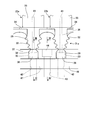
- FIG. 2 is a front view of the main part of the turbine disk in the gas turbine of the present embodiment.
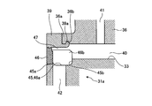
- 3 is a cross-sectional view taken along the line III-III in FIG. 4 is a cross-sectional view taken along the line IV-IV in FIG.
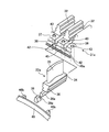
- FIG. 5 is an exploded perspective view of the rotor blade in the gas turbine of the present embodiment.
- FIG. 6 is an explanatory diagram showing the relationship between the diameter and interval of the cooling holes and the stress concentration factor.
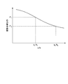
- FIG. 7 is a graph showing a stress concentration factor with respect to the diameter and interval of the cooling holes.
- FIG. 8 is a schematic configuration diagram of the gas turbine of the present embodiment.
- FIG. 9 is a schematic view showing a modification of the turbine disk in the gas turbine of the present embodiment.
- FIG. 1 is a schematic view of a turbine upstream portion of a gas turbine according to an embodiment of the present invention
- FIG. 2 is a front view of a main part of a turbine disk in the gas turbine of the present embodiment
- FIG. FIG. 4 is a sectional view taken along line IV-IV in FIG. 2
- FIG. 5 is an exploded perspective view of a moving blade in the gas turbine of this embodiment
- FIG. 7 is a graph showing a stress concentration coefficient with respect to the diameter and interval of the cooling holes
- FIG. 8 is a schematic configuration diagram of the gas turbine of this embodiment
- FIG. 9 is a gas turbine of this embodiment. It is the schematic showing the modification of the turbine disk in.
- the gas turbine of this embodiment includes a compressor 11, a combustor 12, a turbine 13, and an exhaust chamber 14, and a generator (not shown) is connected to the turbine 13.
- the compressor 11 has an air intake port 15 for taking in air, a plurality of stationary blades 17 and moving blades 18 are alternately arranged in a compressor casing 16, and a bleed manifold 19 is provided on the outside thereof.
- the combustor 12 is combustible by supplying fuel to the compressed air compressed by the compressor 11 and igniting it with a burner.
- a plurality of stationary blades 21 and moving blades 22 are alternately arranged in a turbine casing 20.
- the exhaust chamber 14 has an exhaust diffuser 23 that is continuous with the turbine 13.
- a rotor (turbine shaft) 24 is positioned so as to pass through the center of the compressor 11, the combustor 12, the turbine 13, and the exhaust chamber 14, and an end portion on the compressor 11 side is freely rotatable by a bearing portion 25.
- the end portion on the exhaust chamber 14 side is rotatably supported by the bearing portion 26.
- a plurality of disks are fixed to the rotor 24, the rotor blades 18 and 22 are fixed, and a drive shaft of a generator (not shown) is connected to an end portion on the exhaust chamber 14 side.
- the air taken in from the air intake port 15 of the compressor 11 passes through the plurality of stationary blades 21 and the moving blades 22 and is compressed to become high-temperature and high-pressure compressed air.
- a predetermined fuel is supplied to the compressed air in the combustor 12 and burned.
- the high-temperature and high-pressure combustion gas that is the working fluid generated in the combustor 12 passes through the plurality of stationary blades 21 and the moving blades 22 constituting the turbine 13 to drive and rotate the rotor 24.
- the generator connected to 24 is driven.
- the exhaust gas is converted to static pressure by the exhaust diffuser 23 in the exhaust chamber 14 and then released to the atmosphere.
- the turbine casing 20 is provided with stationary blades 21a, 21b,... Along the fuel gas flow direction (arrow direction in FIG. 1). .. Are provided at equal intervals along the circumferential direction of the turbine casing 20.
- turbine disks 31a, 31b,... are connected to the rotor 24 (see FIG. 8) so as to be integrally rotatable along the axial direction thereof.
- the rotor blades 22a, 22b... are fixed to the outer peripheral portions of the turbine disks 31a, 31b. .. Are provided at equal intervals along the circumferential direction of each turbine disk 31a, 31b.
- the turbine disk 31a has a disk shape, and a plurality of fitting grooves 32 along the axial direction are formed in the outer circumferential portion at equal intervals in the circumferential direction.
- An axial communication groove 33 is formed integrally with the fitting groove 32 below each fitting groove 32.
- the rotor blade main body 35 is erected integrally with the upper surface of the platform 34.
- a blade root portion (fitting protrusion) 36 that can be fitted into the fitting groove 32 is formed integrally with the lower portion of the platform 34.
- a projecting portion 36 a that projects to one side in the axial direction is formed integrally with the lower portion of the blade root portion 36.
- the turbine disk 31a has a circumferential flange portion 37 having a ring shape on one side (front edge side) in the axial direction.
- the circumferential flange portion 37 is formed with a notch 38 that is positioned linearly with each axial communication groove 33.
- the projecting portion 36a of the blade root portion 36 can be fitted into the cutout portion 38 of the turbine disk 31a, and the seal piece 39 can be fitted.
- the blade root portion 36 is slidably fitted into the fitting groove 32 and attached to the turbine disk 31a to the plurality of moving blades 22a. If it demonstrates using FIG. 3, the axial direction communication path 40 will be comprised by forming a clearance gap between the lower surface of the blade root part 36, and the axial direction communication groove 33 at this time.
- the axial communication passage 40 communicates with a cooling passage 41 formed inside the rotor blade 22a.
- the protrusion part 36a of the blade root part 36 fits in the notch part 38 of the turbine disc 31a, and the seal piece 39 fits from the outer side, A part of one side of the axial direction communication path 40 is obstruct
- the seal piece 39 has a hook 39a bent upward from the horizontal.
- the hook 39a is engaged with the notch 36b of the blade root portion 36 in a state where the seal piece 39 is fitted to the notch 38, thereby preventing the seal piece 39 from falling off.
- the axial communication path 40 is closed by fitting a seal piece (not shown) on the other side (rear edge side).
- a plurality of first cooling holes 42 penetrating from the inner side to the outer side of the turbine disk and communicating with the cooling passage 41 of each rotor blade 22a are provided side by side in the circumferential direction.
- a plurality of second cooling holes 43 that are located between the first cooling holes 42 and penetrate from the inside to the outside of the turbine disk are provided in the turbine disk 31a in the circumferential direction.
- the first cooling hole 42 is provided corresponding to the axial communication path 40, and a base end thereof opens to the inside of the turbine casing 20, while a distal end thereof is communicated with the axial communication path 40. Referring to FIG. 4, the base end of the second cooling hole 43 opens to the inside of the turbine casing 20, similarly to the first cooling hole 42.
- the front end portion of the second cooling hole 43 passes through the circumferential flange portion 37 and is closed by fitting the plug 44.
- the turbine disk 31a is formed with a radial communication groove 45 having a ring shape in the flat portion on the outer peripheral side.
- An annular radial communication passage 47 is formed by fixing and closing the seal ring 46 on the opening side of the radial communication groove 45.
- the radial communication groove 45 intersects and communicates with each first cooling hole 42 and each second cooling hole 43.
- the seal ring 46 has a threaded portion 46 a that is screwed into the threaded portion 45 a of the radial communication groove 45 on the inner peripheral portion.
- a plurality of positioning projections 46b that can contact the bottom 45b of the radial communication groove 45 are formed at predetermined intervals in the circumferential direction on the side surface of the radial communication path.
- the seal ring 46 is rotated so that the screw portion 46 a is screwed with the screw portion 45 a, and the positioning protrusion 46 b is abutted against the bottom portion 45 b of the radial communication groove 45, so that the seal ring 46 is positioned and fixed, and the radial communication passage 47. Is formed.
- the first cooling hole 42 and the second cooling hole 43 are communicated with each other through the radial communication path 47.
- the radial communication path 47 is communicated with the axial communication path 40.
- a space portion 52 defined by a turbine disk 31 a and a cover 51 is provided inside the turbine casing 20. Cooling air extracted and cooled from the compressor 11 is supplied to the space 52. The compressed air compressed by the compressor 11 (see FIG. 8) is sent to a cooler (not shown), cooled to a predetermined temperature, and then sent to the space 52. Cooling air (cooling gas) sent to the space 52 is sucked into the cooling holes 42 and 43 through the throttle 53.
- the cooling air is supplied to the axial communication path 40 through the first cooling holes 42, and the radial communication path 47 through the second cooling holes 43. To the axial communication passage 40. By supplying this cooling air from the axial communication path 40 to the cooling path 41, the moving blade 22a is cooled.
- the first cooling holes 42 and the second cooling holes 43 are alternately formed along the circumferential direction, whereby the distance between the cooling holes 42 and 43 is shortened, and the stress concentration is reduced.
- the inner diameter of the cooling holes 42 and 43 is a
- the center distance between the adjacent cooling holes 42 and 43 is b
- the stress concentration coefficient is ⁇ .
- the stress concentration coefficient ⁇ tends to decrease as a / b increases.
- the stress concentration factor sigma 1 for a 1 / b 1 is higher.
- the turbine disk 31a of the present embodiment is solidified to the rotor 24.
- the rotor 24 is rotatably supported.
- a plurality of rotor blades 22a are juxtaposed in the circumferential direction on the outer periphery of the turbine disk 31a.
- first cooling holes 42 penetrating from the inner side to the outer side of the turbine disk and communicating with the cooling passage 41 inside the rotor blade 22a are provided side by side in the circumferential direction.
- the second cooling holes 43 are located between the first cooling holes 42 and penetrate from the inside to the outside of the turbine disk.
- the first cooling holes 42 and the second cooling holes 43 are alternately arranged in the circumferential direction, and the distance between the plurality of cooling holes 42 and 43 in the circumferential direction is reduced. Therefore, the stress concentration acting on the periphery of the cooling holes 42 and 43 when the rotor rotates can be alleviated. Further, by newly providing the second cooling hole 43, the turbine disk 31a can be reduced in weight. As a result, it is possible to improve the durability of the turbine disk 31a.
- the cooling gas can be supplied from the base ends of the first cooling hole 42 and the second cooling hole 43, and the distal ends of the first cooling hole 42 and the second cooling hole 43 are provided. It communicates with a radial communication passage 47 provided along the circumferential direction, and supplies the cooling gas from the first cooling hole 42 and the second cooling hole 43 to the cooling passage 41 of the moving blade 22a through the radial communication passage 47. .
- the pressure loss can be reduced by increasing the passage area of the cooling gas, and the cooling efficiency of the rotor blade 22a can be improved.
- the blade root portions 36 of the rotor blades 22a are fitted into a large number of fitting grooves 32 arranged in parallel in the circumferential direction on the outer peripheral portion, so that the gap between them is aligned along the axial direction.
- An axial communication passage 40 is provided, a first cooling hole 42 is provided in the axial communication passage 40 corresponding to the circumferential direction, and a tip portion communicates with the radial communication passage 47 and the axial communication passage 40 while the second cooling.
- the hole 43 is provided between the first cooling holes 42 in the circumferential direction, the tip is closed by the plug 44 and communicates with the radial communication path 47, and the first cooling hole 42 and the second cooling hole 43 are positioned at appropriate positions.
- the cooling gas is efficiently supplied to the cooling passage 41 of the rotor blade 22a. It is possible to simplify the structure.
- both end portions of the axial communication path 40 are closed by the seal pieces 39.
- the workability of the fitting groove 32 into which the blade root portion 36 of the moving blade 22a is fitted can be improved.
- the seal piece 39 can appropriately form the leak-free axial communication path 40.
- the radial communication passage 47 is provided in an annular shape by closing the radial communication groove 45 having a ring shape with the seal ring 46.
- the workability can be improved by easily configuring the radial communication path 47.
- the seal ring 46 can form a radial communication path 47 that does not leak.
- the compressor 11, the combustor 12, and the turbine 13 are configured, and the turbine 13 is rotatably supported by the turbine disks 31 a, 31 b.
- a plurality of rotor blades 22a, 22b,... Arranged in the circumferential direction on the outer peripheral portion of 31b... And provided with cooling passages 41 therein are provided, and turbine disks 31a, 31b.
- a plurality of first cooling holes 42 penetrating from the inside to the outside and communicating with the cooling passage 41 are juxtaposed in the circumferential direction, and are positioned between the first cooling holes 42 to be outside from the inside of the turbine disk.
- the 2nd cooling hole 43 penetrated toward is provided.
- the first cooling holes 42 and the second cooling holes 43 are alternately arranged in the circumferential direction in the turbine disks 31a, 31b,..., And the distance between the plurality of cooling holes 42, 43 in the circumferential direction. Decrease. The stress concentration acting on the periphery of each cooling hole 42, 43 during rotation can be relaxed. Further, by newly providing the second cooling hole 43, the weight can be reduced and the durability can be improved. As a result, turbine output and efficiency can be improved.
- the first cooling holes 42 are provided from the inner side to the outer side of the turbine disk 31a, and the second cooling holes 42 are provided between the first cooling holes 42 from the inner side to the outer side of the turbine disk.
- the cooling hole 43 is provided, it is not limited to this configuration.
- a plurality of second cooling holes may be provided between the first cooling holes, or the inner diameter of the second cooling holes may be smaller than that of the first cooling holes.
- the hole shape of the 1st cooling hole 42 and the 2nd cooling hole 43 is not restricted to a perfect circle shape, It is good also as unusual shapes, such as elliptical shape.
- providing the first cooling holes 42 and the second cooling holes 43 from the inside to the outside of the turbine disk may be provided so as to be inclined in the axial direction with respect to the circumferential direction, as shown in FIG. Relaxation of stress concentration at the opening of the cooling hole can be realized outside the rotor disk.
- the second cooling hole of the present invention has been described as the second cooling hole 43 provided between the first cooling holes 42 of the turbine disk 31a.
- the second cooling hole may have a closed end without providing the directional communication passage 47. Even in this case, the stress concentration acting on the turbine disk can be reduced and the weight can be reduced. it can.
- the turbine disk and gas turbine according to the present invention are intended to improve durability by reducing stress concentration acting on the turbine disk, and can be applied to any kind of gas turbine.
Landscapes
- Engineering & Computer Science (AREA)
- Mechanical Engineering (AREA)
- General Engineering & Computer Science (AREA)
- Turbine Rotor Nozzle Sealing (AREA)
Abstract
Description
12 燃焼器
13 タービン
14 排気室
21,21a,21b・・・ 静翼
22,22a,22b・・・ 動翼
31a,31b・・・ タービンディスク
32 嵌合溝
36 翼根部(嵌合突起)
39 シールピース
40 軸方向連通路
41 冷却通路
42 第1冷却孔
43 第2冷却孔
44 プラグ
46 シールリング
47 径方向連通路
Claims (6)
- 回転自在に支持されて外周部に複数の動翼が周方向に並設されるタービンディスクにおいて、
タービンディスクの内側から外側に向かって貫通して前記各動翼内部の冷却通路に連通する複数の第1冷却孔が周方向に並設されると共に、
前記各第1冷却孔の間に位置してタービンディスクの内側から外側に向かって貫通する第2冷却孔が設けられる、
ことを特徴とするタービンディスク。 - 前記第1冷却孔と前記第2冷却孔の基端部から冷却ガスを供給可能であると共に、
前記第1冷却孔と前記第2冷却孔の先端部が周方向に沿って設けられた径方向連通路により連通されることを特徴とする請求項1に記載のタービンディスク。 - 外周部に周方向に並設された多数の嵌合溝に前記各動翼の嵌合突起が嵌合することで、両者の隙間に軸方向に沿う軸方向連通路が設けられ、
前記第1冷却孔は、前記軸方向連通路に周方向に対応して設けられ、先端部が前記径方向連通路及び前記軸方向連通路に連通する一方、
前記第2冷却孔は、周方向における前記第1冷却孔の間に設けられ、先端部が閉塞されると共に前記径方向連通路に連通することを特徴とする請求項2に記載のタービンディスク。 - 前記軸方向連通路は、両端部がシールピースにより閉塞されることを特徴とする請求項3に記載のタービンディスク。
- 前記径方向連通路は、リング形状をなす連通溝がシールリングにより閉塞されることで環状に設けられることを特徴とする請求項2から4のいずれか一つに記載のタービンディスク。
- 圧縮機で圧縮した圧縮空気に燃焼器で燃料を供給して燃焼し、発生した燃焼ガスをタービンに供給することで回転動力を得るガスタービンにおいて、
前記タービンは、回転自在に支持されるタービンディスクと、該タービンディスクの外周部に周方向に並設されて内部に冷却通路が設けられる複数の動翼とを有し、
前記タービンディスクに、
タービンディスクの内側から外側に向かって貫通して前記冷却通路に連通する複数の第1冷却孔が周方向に並設されると共に、
前記各第1冷却孔の間に位置してタービンディスクの内側から外側に向かって貫通する第2冷却孔が設けられる、
ことを特徴とするガスタービン。
Priority Applications (4)
| Application Number | Priority Date | Filing Date | Title |
|---|---|---|---|
| EP20090715480 EP2246526B8 (en) | 2008-02-27 | 2009-01-16 | Rotor, turbine disc and gas turbine |
| CN2009801064385A CN101960092B (zh) | 2008-02-27 | 2009-01-16 | 涡轮盘及燃气轮机 |
| US12/864,006 US8770919B2 (en) | 2008-02-27 | 2009-01-16 | Turbine disk and gas turbine |
| KR1020107018233A KR101245094B1 (ko) | 2008-02-27 | 2009-01-16 | 터빈 디스크 및 가스 터빈 |
Applications Claiming Priority (2)
| Application Number | Priority Date | Filing Date | Title |
|---|---|---|---|
| JP2008-046698 | 2008-02-27 | ||
| JP2008046698A JP4939461B2 (ja) | 2008-02-27 | 2008-02-27 | タービンディスク及びガスタービン |
Publications (1)
| Publication Number | Publication Date |
|---|---|
| WO2009107418A1 true WO2009107418A1 (ja) | 2009-09-03 |
Family
ID=41015824
Family Applications (1)
| Application Number | Title | Priority Date | Filing Date |
|---|---|---|---|
| PCT/JP2009/050551 Ceased WO2009107418A1 (ja) | 2008-02-27 | 2009-01-16 | タービンディスク及びガスタービン |
Country Status (6)
| Country | Link |
|---|---|
| US (1) | US8770919B2 (ja) |
| EP (1) | EP2246526B8 (ja) |
| JP (1) | JP4939461B2 (ja) |
| KR (1) | KR101245094B1 (ja) |
| CN (1) | CN101960092B (ja) |
| WO (1) | WO2009107418A1 (ja) |
Families Citing this family (14)
| Publication number | Priority date | Publication date | Assignee | Title |
|---|---|---|---|---|
| US20120183389A1 (en) * | 2011-01-13 | 2012-07-19 | Mhetras Shantanu P | Seal system for cooling fluid flow through a rotor assembly in a gas turbine engine |
| JP5791430B2 (ja) | 2011-08-29 | 2015-10-07 | 三菱日立パワーシステムズ株式会社 | ディスク吊り上げ用治具 |
| CN103233900B (zh) * | 2013-05-09 | 2018-02-06 | 林钧浩 | 管道轮增压通风压缩机 |
| CN104153882B (zh) * | 2013-05-15 | 2017-09-22 | 林钧浩 | 飞行器管道轮燃气发动机 |
| CN105275499B (zh) * | 2015-06-26 | 2016-11-30 | 中航空天发动机研究院有限公司 | 一种具有离心增压和封严效果的双辐板涡轮盘盘心进气结构 |
| US10018065B2 (en) * | 2015-09-04 | 2018-07-10 | Ansaldo Energia Ip Uk Limited | Flow control device for rotating flow supply system |
| KR101663306B1 (ko) * | 2015-10-02 | 2016-10-06 | 두산중공업 주식회사 | 가스터빈 디스크 |
| US10519857B2 (en) | 2016-10-24 | 2019-12-31 | Rolls-Royce Corporation | Disk with lattice features adapted for use in gas turbine engines |
| US11143041B2 (en) * | 2017-01-09 | 2021-10-12 | General Electric Company | Turbine have a first and second rotor disc and a first and second cooling fluid conduit wherein the second cooling fluid conduit is extended through an annular axially extended bore having a radially outer extent defined by a radially innermost surface of the rotor discs |
| JP7328794B2 (ja) | 2019-05-24 | 2023-08-17 | 三菱重工業株式会社 | ロータディスク、ロータ軸、タービンロータ、及びガスタービン |
| CN116201606B (zh) * | 2023-02-17 | 2025-09-23 | 清启动力(北京)科技有限公司 | 一种机械动叶片和轮盘的装配结构及燃气轮机 |
| CN116104586A (zh) * | 2023-04-11 | 2023-05-12 | 中国航发沈阳发动机研究所 | 一种涡轮转子叶片与涡轮盘的锁紧固定结构 |
| DE102023111513A1 (de) * | 2023-05-03 | 2024-11-07 | MTU Aero Engines AG | Rotorscheibe für einen Schaufelkranz |
| WO2025205631A1 (ja) * | 2024-03-27 | 2025-10-02 | 三菱パワー株式会社 | ロータディスク、ロータ軸、タービンロータ、及びガスタービン |
Citations (7)
| Publication number | Priority date | Publication date | Assignee | Title |
|---|---|---|---|---|
| JPS62169201U (ja) * | 1986-04-17 | 1987-10-27 | ||
| JPH0231355U (ja) * | 1988-08-19 | 1990-02-27 | ||
| JPH08218804A (ja) | 1995-02-10 | 1996-08-27 | Mitsubishi Heavy Ind Ltd | タービンのシール装置 |
| JPH11247603A (ja) * | 1997-12-24 | 1999-09-14 | Asea Brown Boveri Ag | 流体機械のロータ |
| JPH11257019A (ja) * | 1998-03-12 | 1999-09-21 | Toshiba Corp | ガスタービン |
| JP2001012205A (ja) * | 1999-06-29 | 2001-01-16 | Mitsubishi Heavy Ind Ltd | ガスタービン動翼冷却流量調整構造 |
| WO2006115484A1 (en) * | 2005-04-25 | 2006-11-02 | Williams International Co., L.L.C. | Gas turbine engine cooling system and method |
Family Cites Families (12)
| Publication number | Priority date | Publication date | Assignee | Title |
|---|---|---|---|---|
| GB617472A (en) * | 1946-10-02 | 1949-02-07 | Adrian Albert Lombard | Improvements in or relating to gas-turbine-engines |
| GB612097A (en) * | 1946-10-09 | 1948-11-08 | English Electric Co Ltd | Improvements in and relating to the cooling of gas turbine rotors |
| JPS62169201A (ja) * | 1986-01-22 | 1987-07-25 | Hitachi Ltd | 機器保護ユニツト |
| JPH0231355A (ja) * | 1988-07-20 | 1990-02-01 | Seiko Epson Corp | ヘッド構造 |
| DE19705442A1 (de) * | 1997-02-13 | 1998-08-20 | Bmw Rolls Royce Gmbh | Turbinen-Laufradscheibe mit Kühlluftkanälen |
| JP3442959B2 (ja) * | 1997-02-21 | 2003-09-02 | 三菱重工業株式会社 | ガスタービン動翼の冷却媒体通路 |
| US5984636A (en) * | 1997-12-17 | 1999-11-16 | Pratt & Whitney Canada Inc. | Cooling arrangement for turbine rotor |
| JP3518447B2 (ja) * | 1999-11-05 | 2004-04-12 | 株式会社日立製作所 | ガスタービン,ガスタービン装置およびガスタービン動翼の冷媒回収方法 |
| JP3361501B2 (ja) * | 2000-03-02 | 2003-01-07 | 株式会社日立製作所 | 閉回路翼冷却タービン |
| GB0405679D0 (en) * | 2004-03-13 | 2004-04-21 | Rolls Royce Plc | A mounting arrangement for turbine blades |
| US6988367B2 (en) * | 2004-04-20 | 2006-01-24 | Williams International Co. L.L.C. | Gas turbine engine cooling system and method |
| JP5129633B2 (ja) * | 2008-03-28 | 2013-01-30 | 三菱重工業株式会社 | 冷却通路用カバーおよび該カバーの製造方法ならびにガスタービン |
-
2008
- 2008-02-27 JP JP2008046698A patent/JP4939461B2/ja active Active
-
2009
- 2009-01-16 US US12/864,006 patent/US8770919B2/en active Active
- 2009-01-16 EP EP20090715480 patent/EP2246526B8/en active Active
- 2009-01-16 CN CN2009801064385A patent/CN101960092B/zh active Active
- 2009-01-16 KR KR1020107018233A patent/KR101245094B1/ko active Active
- 2009-01-16 WO PCT/JP2009/050551 patent/WO2009107418A1/ja not_active Ceased
Patent Citations (7)
| Publication number | Priority date | Publication date | Assignee | Title |
|---|---|---|---|---|
| JPS62169201U (ja) * | 1986-04-17 | 1987-10-27 | ||
| JPH0231355U (ja) * | 1988-08-19 | 1990-02-27 | ||
| JPH08218804A (ja) | 1995-02-10 | 1996-08-27 | Mitsubishi Heavy Ind Ltd | タービンのシール装置 |
| JPH11247603A (ja) * | 1997-12-24 | 1999-09-14 | Asea Brown Boveri Ag | 流体機械のロータ |
| JPH11257019A (ja) * | 1998-03-12 | 1999-09-21 | Toshiba Corp | ガスタービン |
| JP2001012205A (ja) * | 1999-06-29 | 2001-01-16 | Mitsubishi Heavy Ind Ltd | ガスタービン動翼冷却流量調整構造 |
| WO2006115484A1 (en) * | 2005-04-25 | 2006-11-02 | Williams International Co., L.L.C. | Gas turbine engine cooling system and method |
Non-Patent Citations (1)
| Title |
|---|
| See also references of EP2246526A4 * |
Also Published As
| Publication number | Publication date |
|---|---|
| EP2246526A1 (en) | 2010-11-03 |
| JP2009203870A (ja) | 2009-09-10 |
| EP2246526B1 (en) | 2015-03-18 |
| CN101960092B (zh) | 2013-09-11 |
| KR101245094B1 (ko) | 2013-03-18 |
| US8770919B2 (en) | 2014-07-08 |
| EP2246526A4 (en) | 2014-03-05 |
| US20100290922A1 (en) | 2010-11-18 |
| KR20100116619A (ko) | 2010-11-01 |
| JP4939461B2 (ja) | 2012-05-23 |
| CN101960092A (zh) | 2011-01-26 |
| EP2246526B8 (en) | 2015-04-22 |
Similar Documents
| Publication | Publication Date | Title |
|---|---|---|
| JP4939461B2 (ja) | タービンディスク及びガスタービン | |
| CN105637199B (zh) | 燃气轮机 | |
| CN114075998B (zh) | 涡轮动叶的密封组装结构和包含其的燃气轮机以及涡轮动叶的密封组装方法 | |
| CN108138655B (zh) | 燃气轮机转子、燃气轮机以及燃气轮机设备 | |
| WO2017188040A1 (ja) | ガスタービン | |
| JP5863894B2 (ja) | 動翼体及び回転機械 | |
| JP5675282B2 (ja) | 動翼体及び回転機械 | |
| US11035240B2 (en) | Turbine vane assembly and gas turbine including the same | |
| CN109667627A (zh) | 燃气轮机的转子轮盘总成 | |
| KR20190047841A (ko) | 가스 터빈 | |
| KR101986021B1 (ko) | 씰링어셈블리 및 이를 포함하는 가스터빈 | |
| JP4773810B2 (ja) | ガスタービン | |
| WO2021039531A1 (ja) | 圧縮機、ガスタービン | |
| KR101914879B1 (ko) | 터빈 블레이드 및 이를 포함하는 터빈 및 가스터빈 | |
| JP2007146787A (ja) | ガスタービン | |
| KR101955116B1 (ko) | 터빈 베인, 터빈 및 이를 포함하는 가스터빈 | |
| KR101965505B1 (ko) | 터빈 블레이드 링 세그멘트 및 이를 포함하는 터빈 및 가스터빈 | |
| US11111803B2 (en) | Sealing structure between turbine rotor disk and interstage disk | |
| EP3456922B1 (en) | Turbine blade with cooling structure, turbine including same turbine blade, and gas turbine including same turbine | |
| KR101985098B1 (ko) | 가스 터빈 | |
| KR101958110B1 (ko) | 터빈 스테이터, 터빈 및 이를 포함하는 가스터빈 | |
| KR101965506B1 (ko) | 터빈 로터, 터빈 및 이를 포함하는 가스터빈 | |
| KR102887774B1 (ko) | 터빈 블레이드의 씰 조립구조와 이를 포함하는 가스 터빈 | |
| KR101984397B1 (ko) | 로터, 터빈 및 이를 포함하는 가스터빈 | |
| KR20190043870A (ko) | 가스 터빈 디스크 |
Legal Events
| Date | Code | Title | Description |
|---|---|---|---|
| WWE | Wipo information: entry into national phase |
Ref document number: 200980106438.5 Country of ref document: CN |
|
| 121 | Ep: the epo has been informed by wipo that ep was designated in this application |
Ref document number: 09715480 Country of ref document: EP Kind code of ref document: A1 |
|
| WWE | Wipo information: entry into national phase |
Ref document number: 2009715480 Country of ref document: EP |
|
| WWE | Wipo information: entry into national phase |
Ref document number: 12864006 Country of ref document: US |
|
| ENP | Entry into the national phase |
Ref document number: 20107018233 Country of ref document: KR Kind code of ref document: A |
|
| NENP | Non-entry into the national phase |
Ref country code: DE |