WO2009107643A1 - ベルト組立用治具およびベルト組立方法ならびにベルト製造方法 - Google Patents
ベルト組立用治具およびベルト組立方法ならびにベルト製造方法 Download PDFInfo
- Publication number
- WO2009107643A1 WO2009107643A1 PCT/JP2009/053381 JP2009053381W WO2009107643A1 WO 2009107643 A1 WO2009107643 A1 WO 2009107643A1 JP 2009053381 W JP2009053381 W JP 2009053381W WO 2009107643 A1 WO2009107643 A1 WO 2009107643A1
- Authority
- WO
- WIPO (PCT)
- Prior art keywords
- ring
- belt
- curvature
- radius
- elements
- Prior art date
- Legal status (The legal status is an assumption and is not a legal conclusion. Google has not performed a legal analysis and makes no representation as to the accuracy of the status listed.)
- Ceased
Links
Images





Classifications
-
- F—MECHANICAL ENGINEERING; LIGHTING; HEATING; WEAPONS; BLASTING
- F16—ENGINEERING ELEMENTS AND UNITS; GENERAL MEASURES FOR PRODUCING AND MAINTAINING EFFECTIVE FUNCTIONING OF MACHINES OR INSTALLATIONS; THERMAL INSULATION IN GENERAL
- F16G—BELTS, CABLES, OR ROPES, PREDOMINANTLY USED FOR DRIVING PURPOSES; CHAINS; FITTINGS PREDOMINANTLY USED THEREFOR
- F16G5/00—V-belts, i.e. belts of tapered cross-section
- F16G5/16—V-belts, i.e. belts of tapered cross-section consisting of several parts
-
- B—PERFORMING OPERATIONS; TRANSPORTING
- B29—WORKING OF PLASTICS; WORKING OF SUBSTANCES IN A PLASTIC STATE IN GENERAL
- B29D—PRODUCING PARTICULAR ARTICLES FROM PLASTICS OR FROM SUBSTANCES IN A PLASTIC STATE
- B29D29/00—Producing belts or bands
-
- Y—GENERAL TAGGING OF NEW TECHNOLOGICAL DEVELOPMENTS; GENERAL TAGGING OF CROSS-SECTIONAL TECHNOLOGIES SPANNING OVER SEVERAL SECTIONS OF THE IPC; TECHNICAL SUBJECTS COVERED BY FORMER USPC CROSS-REFERENCE ART COLLECTIONS [XRACs] AND DIGESTS
- Y10—TECHNICAL SUBJECTS COVERED BY FORMER USPC
- Y10T—TECHNICAL SUBJECTS COVERED BY FORMER US CLASSIFICATION
- Y10T29/00—Metal working
- Y10T29/49—Method of mechanical manufacture
- Y10T29/49826—Assembling or joining
- Y10T29/49895—Associating parts by use of aligning means [e.g., use of a drift pin or a "fixture"]
- Y10T29/49899—Associating parts by use of aligning means [e.g., use of a drift pin or a "fixture"] by multiple cooperating aligning means
-
- Y—GENERAL TAGGING OF NEW TECHNOLOGICAL DEVELOPMENTS; GENERAL TAGGING OF CROSS-SECTIONAL TECHNOLOGIES SPANNING OVER SEVERAL SECTIONS OF THE IPC; TECHNICAL SUBJECTS COVERED BY FORMER USPC CROSS-REFERENCE ART COLLECTIONS [XRACs] AND DIGESTS
- Y10—TECHNICAL SUBJECTS COVERED BY FORMER USPC
- Y10T—TECHNICAL SUBJECTS COVERED BY FORMER US CLASSIFICATION
- Y10T29/00—Metal working
- Y10T29/53—Means to assemble or disassemble
- Y10T29/53961—Means to assemble or disassemble with work-holder for assembly
Definitions
- the present invention relates to a jig, an assembling method, and a manufacturing method for assembling a belt constituted by arranging a large number of plate-like elements facing each other in an annular shape and binding these elements by a ring. .
- This type of belt is configured to transmit torque by the pressing force between the metal pieces arranged in contact with each other, and the metal piece sandwiched in the winding groove in the pulley on the driving side, By rotating the pulley, the pulley is sequentially pushed out from the winding groove to press the preceding metal piece. As the metal piece thus advanced enters the winding groove in the driven pulley, torque is transmitted to the driven pulley as the metal piece advances.
- FIG. 7 shows the shape of the block 100.
- the block 100 shown here is annularly arranged so that the short side is the inner peripheral side.
- the left and right side portions 101 and 102 in the arrangement state are inclined corresponding to the tapered inner surface of the V-shaped winding groove in the pulley (not shown).
- a saddle surface 104 around which the endless carrier 103 is wound is formed at substantially the center in the vertical direction and the width direction.
- the saddle surface 104 is formed to have a width equal to or larger than the width of the two endless carriers 103 arranged side by side in the width direction.
- locking portions 105 and 106 for preventing the block 100 from coming off the endless carrier 103 are provided.
- These locking portions 105, 106 cover the left and right side portions of the saddle surface 104 or the upper sides of the left and right side portions of the endless carrier 103 placed on the saddle surface 104, and rise on both the left and right sides of the saddle surface 104.
- it is an inverted L-shaped portion, and the gaps 105 and 106 are open to form an opening 107 for the saddle surface 104.
- convex portions 108 and 109 having a circular cross section are formed at two positions on the left and right sides of one surface (for example, the front surface) of the locking portions 105 and 106, and on the surface opposite to the convex portions 108 and 109.
- a recess (not shown) for fitting the protrusions 108 and 109 is formed.
- the endless carrier that binds the blocks which are metal pieces arranged in an annular shape, not only contacts the saddle surface and binds the blocks, but also pulls out the blocks from the winding groove in the pulley. Therefore, as described in JP 2000-205342 A, a locking portion is essential.
- the endless carrier is arranged at the center in the width direction of the block, the locking portions are provided on both the left and right sides of the block. Both side edges of the carrier will be engaged.
- the interval between the locking portions that is, the width of the opening is narrower than the width of the entire endless carrier in a state where the blocks are bound. Therefore, when the endless carrier and the block are assembled to each other, if the endless carrier and the block are arranged at the same relative positions as after the completion of the assembly, the endless carrier cannot pass through the opening in the block, so that they cannot be assembled to each other. . For this reason, it is necessary to devise some means to assemble the blocks on the endless carrier. However, in the past, a method or apparatus for assembling a large number of blocks to the endless carrier has not been developed.
- the present invention has been made paying attention to the above technical problem, and has as its object to efficiently assemble or manufacture a belt comprising a large number of elements and a ring for binding them in an annular shape.
- the belt assembling jig of the present invention is a belt assembling jig for assembling a belt formed by bundling a large number of plate-like elements arranged in an annular shape with a uniform posture, and the ring for assembling the elements sequentially. And a holding member that holds a part of the head so that the radius of curvature of the part is larger than the radius of curvature of the other part.
- the element includes a saddle surface on which the ring is mounted, and a retaining portion that is formed to project to the outer peripheral side in the annularly arranged state on both the left and right sides of the saddle surface and prevents the ring on the saddle surface from coming off. ing.
- the holding member can be configured to hold the ring so that the curvature radius of a part of the ring is larger than the curvature radius of the other part when the shape of the entire ring is an oval shape or an elliptical shape.
- the belt is configured by bundling a plurality of elements by a plurality of rings arranged adjacent to each other in the width direction, and the holding member has at least two rings adjacent to each other in the width direction and in parallel. It is preferably configured to be held side by side.
- the holding member includes at least a pair of expansion members having an arc surface around which the ring is wound on the outer peripheral portion and having a mutual interval widened so as to apply tension to the ring.
- the holding member can include a shape holder that regulates the position of the outer peripheral surface of the ring and holds the ring in an oval shape or an elliptical shape.
- the belt assembling method and the belt manufacturing method according to the present invention are a method of assembling a belt formed by bundling a large number of plate-like elements arranged in an annular shape with the same posture, and the ring has a radius of curvature of a part thereof. Is held so as to be larger than the radius of curvature of the other part, and the element is sequentially assembled to the part of the ring in a state in which the element is prevented from coming off from the ring.
- the element includes a saddle surface on which the ring is placed, and a retaining portion that protrudes toward the outer peripheral side in a state of being annularly arranged on both the left and right sides of the saddle surface and prevents the ring on the saddle surface from coming off. Yes.
- the ring can be held so that the radius of curvature of a part of the ring is larger than the radius of curvature of the other part by making the entire shape into an oval shape or an oval shape.
- the belt is configured by bundling a plurality of elements by a plurality of rings arranged adjacent to each other in the width direction and holding at least two rings adjacent to each other in the width direction and arranged in parallel. It is preferable to assemble an element with respect to these two rings.
- the ring for binding the elements is an endless ring as a whole.
- the radius of curvature of a part of the ring is larger than that of the other part, that is, a part of the ring is straight or If the shape is close to that, it becomes easier to deform that part than other parts. Therefore, when assembling the element to the ring, by assembling to the part having a large curvature radius, the part of the ring is deformed into a shape matched to the element, and the deformation operation is easily performed for assembling. As a result, the assembly operation or the belt assembly operation as a whole can be easily and efficiently performed.
- an element comprising a saddle surface on which a ring is placed, and a retaining portion that protrudes to the outer peripheral side in an annular arrangement on both the left and right sides of the saddle surface and prevents the ring on the saddle surface from coming off. If there is a retaining portion that engages the left and right edges of the ring on the saddle surface to prevent it from coming off, even if it is formed on both the left and right sides of the saddle surface, it is held in a straight line shape or a state close thereto.
- the element can be assembled to the ring by deforming a part of the ring.
- the holding member has a configuration for holding the ring so that the curvature radius of a part of the ring is larger than the curvature radius of the other part when the shape of the entire ring becomes an oval shape or an elliptical shape
- the whole becomes an ellipse or an ellipse
- a part of the part becomes a straight line having a larger radius of curvature than other parts or a state close to this part.
- the element can be assembled easily.
- the belt is configured by bundling a plurality of elements by a plurality of rings arranged in parallel adjacent to each other in the width direction, and the holding member has at least two of the rings adjacent to each other in the width direction and in parallel.
- the belt is configured by binding a plurality of elements by a plurality of rings arranged adjacent to each other in the width direction in parallel.
- One of the rings can be deformed at a large portion and a part can be overlapped with the other ring, and the operation can be facilitated. Therefore, the assembly of the element or the assembly of the belt becomes easy, and the manufacturability of the belt can be improved.
- the holding member includes at least a pair of expansion members having an arc surface on which the ring is wound on the outer peripheral portion and the mutual distance is increased so as to apply tension to the ring, the interval between the expansion members is increased.
- the mutually symmetrical portions of the rings wound around these are pulled outward in the radial direction. Therefore, a portion located in the middle of them can be linear or a shape close to this, that is, a part of the radius of curvature can be increased.
- the holding member includes a shape holder that regulates the position of the outer peripheral surface of the ring and holds the ring in an oval shape or an elliptical shape
- the positions of a plurality of locations on the outer peripheral surface of the ring are regulated.
- the ring has its own elasticity and has a shape that gently connects their restricting positions.
- the belt assembling method or the belt manufacturing method of the present invention when an element is assembled to a ring, a part of the ring is extended in a straight line shape or a shape close thereto, and is assembled to that part.
- the element can be easily deformed, for example, bent, so that the element can be easily assembled to the ring, and the manufacturability of the belt can be improved.
- the element has a saddle surface on which the ring is placed, and a retaining portion that protrudes to the outer peripheral side in an annular arrangement on both the left and right sides of the saddle surface and prevents the ring on the saddle surface from coming off
- the retaining portions for retaining the right and left side edges of the ring on the saddle surface are held straight.
- the element can be assembled to the ring by deforming a part of the ring. That is, the ring can be inserted into the saddle surface by passing between the retaining portions. In this case, since a part of the ring can be easily deformed, the assembly of the elements becomes easy, and as a result, the belt can be efficiently assembled to improve the manufacturability.
- the ring when the ring is held in such a manner that the curvature radius of one part of the ring is larger than the curvature radius of the other part due to the overall shape of the ring being an ellipse or an ellipse, the symmetrical points in the ring are mutually connected.
- the whole becomes an oval shape or an ellipse shape, and a part of the part becomes a straight line having a larger curvature radius than the other part or a state close to this, and the element is easily assembled to that part. be able to.
- the belt is configured by bundling a plurality of elements by a plurality of rings arranged in parallel adjacent to each other in the width direction, and at least two rings are adjacent to each other in the width direction and held side by side in parallel.
- the belt is formed by bundling a plurality of elements by a plurality of the rings arranged in parallel adjacent to each other in the width direction.
- One ring can be deformed at a relatively large part and a part can be overlapped with the other ring, and the operation can be facilitated, so that the assembly of the element or the belt can be facilitated.
- the manufacturability can be improved.
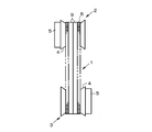
- FIG. 4 is a cross-sectional view taken along line IV-IV in FIG. 3. It is a schematic diagram of the continuously variable transmission using the belt made into object by this invention. It is a front view of the element which comprises the belt made into object by this invention. It is a front view of the block which comprises the conventional belt.
- the belt is used, for example, in a continuously variable transmission, and is sandwiched in a winding groove having a V-shaped cross section formed on the outer peripheral portion of the pulley, and as a result, a frictional force generated between the belt and the pulley. It is configured to transmit torque.
- An example thereof is schematically shown in FIG. 5, and the belt 1 is wound around a driving pulley 2 and a driven pulley 3 that constitute a continuously variable transmission.
- Each of these pulleys 2 and 3 has a fixed sheave and a movable sheave each provided with a tapered surface so as to face each other, thereby forming a winding groove 4 having a V-shaped cross section between these sheaves.
- the movable sheave is configured to change the width of the winding groove 4 by moving the movable sheave back and forth with respect to the fixed sheave by an actuator 5 such as a hydraulic cylinder.
- the belt used in this manner is formed by annularly binding a number of elements with a ring so that the entire belt has an annular shape and both side surfaces are V-shaped or tapered.
- An example of the element 6 constituting the belt 1 shown in FIG. 5 is shown in FIG.
- the element 6 is a metal plate piece, and elements having the same shape and size are arranged in an annular shape with the same posture.
- a convex portion called a dimple 7 and a concave portion (not shown) called a hole into which the dimple 7 is loosely fitted. are formed at one location on both the front and back sides of the element.
- the dimple 7 is formed so as to protrude from the back surface or the front surface as a hole is formed by pressing one portion of the front surface or back surface of the element 6 in the thickness direction to form a hole. Therefore, when the dimple 7 is fitted into the hole of the adjacent element 6, the relative movement of the element 6 in the radial direction, that is, the vertical direction and the horizontal direction is restricted.
- each element 6 is arranged in a ring shape, there is always a place where each element 6 is arranged in a so-called fan-shaped (radial) open state around the center of curvature of the belt 1 without being parallel.
- a locking edge 8 is formed on the element 6 to allow a fan-shaped arrangement with the elements 6 in contact with each other.
- the rocking edge 8 is a boundary line or a boundary region where the thickness of the element changes, and the width direction (direction parallel to the rotation center axis of the pulley) is substantially at the center of the element 6 in the height direction. ).
- the peripheral length on the upper side of the element 6 (the outer peripheral side as the belt 1) becomes longer. Since the circumference of the lower side of the element 6 (inner circumference side as the belt 1) becomes shorter, the interval between the elements 6 becomes narrower. Therefore, the lower part of the element 6 is configured to be thin at the lower end side, and the portion where the plate thickness changes between the upper side and the lower side of the element is the rocking edge 8. Therefore, each element 6 rotates in the plate thickness direction around the rocking edge 8, that is, pitching occurs and opens like a fan as described above.
- the locking edge 8 may be formed on either one of the front and back surfaces. For example, the locking edge 8 is formed on the surface from which the dimple 7 protrudes.
- each element 6 has a saddle surface 10 on which a ring 9 is placed (placed). Since the saddle surface 10 is in contact with a ring 9 that binds a large number of elements 6, the contact pressure increases when the belt 1 is transmitting torque, whereas the element 6 In the case where the pulleys 2 and 3 are wound around the pulleys 2 and 3 and opened in a fan shape from the linearly arranged state, sliding occurs between the ring 9 and the saddle surface 10, and accordingly, a large frictional force is generated.
- the saddle surface 10 is formed at a position as close as possible to the aforementioned locking edge 8 so that the moment due to the frictional force does not increase. Therefore, the saddle surface 10 is formed at a substantially central portion of each element 6 in the vertical direction.
- the ring 9 in the belt 1 is formed by laminating thin metal strips, and the two rings 9 are arranged adjacent to the saddle surface 10 in the width direction so as to bind the elements 6. It is configured.
- the saddle surface 10 is formed to have a width equal to or greater than the width of the two rings 9 arranged in parallel.
- the ring is placed on the saddle surface and binds the elements so that the elements maintain an annular arrangement so that the elements do not separate outward in the radial direction.
- the ring also acts to pull out the element from the winding groove when the element is fed out from the winding groove of the pulley. Therefore, in order to prevent the ring from coming out of the element in the radial direction, a retaining portion for holding the ring in a state of being sandwiched between the saddle surface is provided.
- hook portions 11 are provided on both the left and right sides of the element 6, as hooking portions 11 extending upward from the saddle surface 10 and covering a part of the upper side of the saddle surface 10.
- the hook portion 11 is a hook-shaped (inverted L-shaped) portion, and the left and right side edges of the ring 9 arranged in parallel with the saddle surface 10 are connected to the saddle surface 10. It is designed to be loosely sandwiched between the two. Therefore, the tip portions of the hook portions 11 are separated from each other, and an opening portion 12 for the saddle surface 10 is formed here.
- the interval between the hook portions 11, in other words, the opening width of the saddle surface 10 is wider than the width of one ring 9 and smaller than the sum of the widths of the two rings 9.
- an example of the belt 1 that is the subject of the present invention is that the width of any one (one) ring 9 is narrower than the width of the opening 12 in the element 6 and two (two) rings 9. Is wider than the width of the opening 12 in the element 6. Therefore, after assembling all the elements 6 to any one ring 9 and then assembling the other ring 9 to those elements 6, the element 6 falls off in the process of assembling the other ring 9. Cannot be assembled. Further, in the state in which the two rings 9 are adjacent to each other in the width direction and arranged in parallel to each other in the same manner as in the assembled state as the belt 1, the entire width becomes wider than the width of the opening 12, so the saddle of the element 6 The surface 10 cannot be inserted as it is. Therefore, in the present invention, the belt 1 is assembled or manufactured by the method described below using the following jig.
- FIG. 1 is a schematic front view of a jig according to the present invention, and a jig 20 shown here is an elliptical shape or a ring in which two rings 9 constituting the belt 1 described above are adjacent to each other in parallel. It is configured to be held in an oval shape. That is, an actuator 22 that causes the pair of rods 21 to protrude in the opposite directions in the substantially horizontal direction and to move backward is disposed on the base 23.
- the actuator 22 has a configuration in which the rod 21 is advanced and retracted by rotating a pinion meshed with a rack integral with each rod 21 by a motor (each not shown), a configuration in which the rod is advanced and retracted by hydraulic pressure,
- a configuration in which the rod is advanced and retracted by hydraulic pressure An appropriate configuration such as a configuration in which the pinion is rotated manually instead of a motor, a configuration in which thrust is constantly applied to the rod 21 by an elastic force generation mechanism such as a spring, or the like can be adopted as necessary. .
- a pusher 24 corresponding to the holding member or the expansion member in the present invention is provided at the tip of each rod 21.
- the pusher 24 is used to hold the two rings 9 arranged in parallel with each other while maintaining the arrangement state and to apply a predetermined tension. Therefore, the pusher 24 has a smooth curved surface so as not to bend the ring 9. It is configured to hold the ring 9.
- the pusher 24 can be constituted by a grooved roller or a semicircular support that can fit the two rings 9 in a parallel state, and FIG. 1 shows a semicircular roller. An example is shown.
- FIG. 1 shows a state in which the ring 9 is held in an elliptical shape.
- the element 6 is assembled with a small curvature (the radius of curvature). Assembling is performed on the upper part of the middle part C, particularly the middle part of the upper and lower parts.
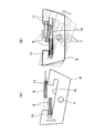
- the assembling procedure (method) is shown in FIG.
- the element 6 includes the hook portions 11 on both the left and right sides of the saddle surface 10 as described above, first, the inner portion C of the ring 9 is arranged so that the opening portion 12 faces the inner peripheral surface of the ring 9.
- the element 6 is inserted into the circumferential side, and one hook portion 11 is hooked on the side edge portion (so-called outer side edge portion) of one of the rings 9, and in this state, as shown in FIG.
- the one ring 9 together with the element 6 is pulled down to the inner peripheral side.
- the two rings 9 arranged with the side edges approaching or contacting each other are shifted vertically.
- the overall width of the double ring 9 is larger than the width of the opening 12 of the element 6, and therefore the other ring 9 cannot be inserted into the saddle surface 10.
- the upper ring 9 that is, the ring 9 not yet placed on the saddle surface 10 side of the element 6 is directed toward the outer peripheral side of the ring 9 pulled down together with the element 6.
- To move in the width direction This is performed by deforming a part of the ring 9 in the width direction.
- the portion where the element 6 is assembled has a large curvature radius as described above, and is easily deformed. Therefore, a part of each ring 9 can be easily overlapped vertically.
- the ring 9 moved in the width direction does not move in parallel as a whole, and as shown in FIG. 2B, a part of the ring 9 moves with twisting, and the upper ring 9 is inclined. Part of the lever overlaps the lower ring 9.
- the element 6 is centered on one hook portion 11 (the left hook portion 11 in FIG. 2) in the counterclockwise direction in FIG. If it rotates, the other hook part 11 will be lifted and the side edge part of the outer side of the ring 9 which overlaps with the upper side will pass the opening part 12, and will enter into the saddle surface 10 side.
- the rings 9 are arranged in parallel, so that the assembly of the element 6 to the double ring 9 is completed.
- the element 6 that has been assembled is moved along the ring 9, the portion C having a small curvature in the ring 9, that is, the assembly site C is vacated, and the subsequent element 6 is assembled to the ring 9 in the same procedure as described above. .
- the above elements 6 may be assembled one by one, or a plurality of elements 6 may be placed in a suitable holder or cartridge (not shown) and assembled to the ring 9 in a lump. Good.
- an automatic machine or industrial robot (not shown) that can move the element 6 as described above is prepared, and can be automatically assembled by the automatic machine or industrial robot. it can.
- the element 6 also advances to the portion pressed by the pusher 24. In this case, the pusher 24 is moved backward by the dimension of the element 6 and the ring 9 is moved to the element 6 And hold the entire shape in the shape shown in FIG.
- a portion C having a large curvature radius (small curvature) is generated in the two rings 9 held by the jig 20, and a part of the ring 9 is bent or twisted easily at that portion. And can be displaced. Therefore, the hook portions 11 are formed on both the left and right sides of the saddle surface 10, and even if the width of the opening 12 between the hook portions 11 is narrower than the width of the double ring 9, The element 6 can be easily assembled by causing displacement and deformation. As a result, the belt 1 can be efficiently assembled and its manufacturability can be improved.
- the present invention is not limited to the specific examples described above, and the assembly jig according to the present invention applies a compressive force to the ring 9 in addition to a configuration in which tension is applied to the ring 9 to hold the ring 9 in a predetermined shape.
- maintains 9 in an ellipse shape or an ellipse shape may be sufficient.
- An example thereof is schematically shown in FIG. 3, and a plurality of so-called linear motion type actuators 30 are arranged on the outer peripheral side of the two-ring 9. These actuators 30 are electric or hydraulic actuators configured to move the rod 31 forward and backward, and are arranged toward the inner periphery of the ring 9 or toward the center of the ring 9. Yes.
- a ring pressing member 32 is attached to the tip of the rod 31 in each actuator 30.
- the ring pressing members 32 hold the rings 9 in an appropriate shape such as an elliptical shape or an oval shape by pressing the outer peripheral surfaces of the two adjacent rings 9 arranged in parallel adjacent to each other.
- the pressing surface is a flat surface so as to hold the ring 9 by the frictional force generated by pressing the ring 9.
- positioning annularly) of the element 6 You may have a recessed part along the outline of a part.
- the ring 9 is held in a desired shape such as an oval shape or an oval shape by appropriately adjusting the pressing force of each part of the ring 9 by each actuator 30. be able to. Then, the radius of curvature of a part of the ring 9 becomes larger than that of the other part, and the ring 9 can be easily bent or twisted at the part.
- the element 6 can be easily assembled to the double ring 9.
- the present invention is not limited to a jig and a method for assembling a belt using the two-ring 9, and the present invention is basically related to the side edge portions of the ring on the right and left hook portions. It is only necessary to be configured so as to prevent them from coming off, and therefore, a plurality of rings may be used.
- the holding member in the present invention is not limited to the configuration provided with a drive mechanism such as an actuator.
- a frame or the like that holds and holds about half or one third of the entire circumference of the ring. It may be of a structure.
Landscapes
- Engineering & Computer Science (AREA)
- General Engineering & Computer Science (AREA)
- Mechanical Engineering (AREA)
- Devices For Conveying Motion By Means Of Endless Flexible Members (AREA)
- Clamps And Clips (AREA)
Abstract
Description
Claims (14)
- 姿勢を揃えて環状に配列された板片状の多数のエレメントをリングによって結束してなるベルトを組み立てるベルト組立用治具において、
前記エレメントを順次組み付ける前記リングにおける一部を、該一部の曲率半径が他の部分の曲率半径より大きくなるように保持する保持部材を備えていることを特徴とするベルト組立用治具。 - 前記エレメントは、前記リングを載せるサドル面と、そのサドル面の左右両側に前記環状に配列した状態で外周側に突出して形成されかつ前記サドル面上のリングを抜け止めする抜け止め部とを備えている請求項1に記載のベルト組立用治具。
- 前記保持部材は、前記リング全体の形状が長円形状もしくは楕円形状となることにより前記一部の曲率半径が他の部分の曲率半径より大きくなるように前記リングを保持する構成を備えている請求項1または2に記載のベルト組立用治具。
- 前記ベルトは、互いに幅方向に隣接させて平行に配列された複数の前記リングによって複数の前記エレメントを結束して構成され、
前記保持部材は、少なくとも二条の前記リングをその幅方向に互いに隣接させかつ平行に並べて保持するように構成されている請求項1ないし3のいずれかに記載のベルト組立用治具。 - 前記保持部材は、前記リングが巻き掛けられる円弧面を外周部に有しかつ前記リングに張力を付与するように相互の間隔が拡げられる少なくとも一対の拡張部材を含む請求項1ないし4のいずれかに記載のベルト組立用治具。
- 前記保持部材は、前記リングの外周面の位置を規制して前記リングを長円形状もしくは楕円形状に保持する形状保持具を含む請求項1ないし4のいずれかに記載のベルト組立用治具。
- 姿勢を揃えて環状に配列された板片状の多数のエレメントをリングによって結束してなるベルトを組み立てるベルト組立方法において、
前記リングをその一部の曲率半径が他の部分の曲率半径より大きくなるように保持し、そのリングにおける前記一部に前記エレメントをリングに対して抜け止めした状態に順次組み付けることを特徴とするベルト組立方法。 - 前記エレメントは、前記リングを載せるサドル面と、そのサドル面の左右両側に前記環状に配列した状態で外周側に突出して形成されかつ前記サドル面上のリングを抜け止めする抜け止め部とを備えている請求項7に記載のベルト組立方法。
- 前記リングを、その全体の形状が長円形状もしくは楕円形状となることにより前記一部の曲率半径が他の部分の曲率半径より大きくなるように保持する請求項7または8に記載のベルト組立方法。
- 前記ベルトは、互いに幅方向に隣接させて平行に配列された複数の前記リングによって複数の前記エレメントを結束して構成され、
少なくとも二条の前記リングをその幅方向に互いに隣接させかつ平行に並べて保持し、
これら二条のリングに対して前記エレメントを組み付ける請求項7ないし9のいずれかに記載のベルト組立方法。 - 姿勢を揃えて環状に配列された板片状の多数のエレメントをリングによって結束してなるベルトを製造するベルト製造方法において、
前記リングをその一部の曲率半径が他の部分の曲率半径より大きくなるように保持し、そのリングにおける前記一部に前記エレメントをリングに対して抜け止めした状態に順次組み付けることを特徴とするベルト製造方法。 - 前記エレメントは、前記リングを載せるサドル面と、そのサドル面の左右両側に前記環状に配列した状態で外周側に突出して形成されかつ前記サドル面上のリングを抜け止めする抜け止め部とを備えている請求項11に記載のベルト製造方法。
- 前記リングを、その全体の形状が長円形状もしくは楕円形状となることにより前記一部の曲率半径が他の部分の曲率半径より大きくなるように保持する請求項11または13に記載のベルト製造方法。
- 前記ベルトは、互いに幅方向に隣接させて平行に配列された複数の前記リングによって複数の前記エレメントを結束して構成され、
少なくとも二条の前記リングをその幅方向に互いに隣接させかつ平行に並べて保持し、
これら二条のリングに対して前記エレメントを組み付ける請求項11ないし13のいずれかに記載のベルト製造方法。
Priority Applications (3)
| Application Number | Priority Date | Filing Date | Title |
|---|---|---|---|
| US12/919,710 US20100325866A1 (en) | 2008-02-28 | 2009-02-25 | Belt assembling device, belt assembling method, and belt manufacturing method |
| EP09714432A EP2246589A4 (en) | 2008-02-28 | 2009-02-25 | DEVICE FOR ASSEMBLING A TAPE, METHOD FOR ASSEMBLING A TAPE AND METHOD FOR PRODUCING THE TAPE |
| CN2009801068085A CN101960168A (zh) | 2008-02-28 | 2009-02-25 | 带组装用夹具、带组装方法以及带制造方法 |
Applications Claiming Priority (2)
| Application Number | Priority Date | Filing Date | Title |
|---|---|---|---|
| JP2008-047851 | 2008-02-28 | ||
| JP2008047851A JP4743217B2 (ja) | 2008-02-28 | 2008-02-28 | ベルト組立用治具およびベルト組立方法 |
Publications (1)
| Publication Number | Publication Date |
|---|---|
| WO2009107643A1 true WO2009107643A1 (ja) | 2009-09-03 |
Family
ID=41016032
Family Applications (1)
| Application Number | Title | Priority Date | Filing Date |
|---|---|---|---|
| PCT/JP2009/053381 Ceased WO2009107643A1 (ja) | 2008-02-28 | 2009-02-25 | ベルト組立用治具およびベルト組立方法ならびにベルト製造方法 |
Country Status (5)
| Country | Link |
|---|---|
| US (1) | US20100325866A1 (ja) |
| EP (1) | EP2246589A4 (ja) |
| JP (1) | JP4743217B2 (ja) |
| CN (1) | CN101960168A (ja) |
| WO (1) | WO2009107643A1 (ja) |
Families Citing this family (3)
| Publication number | Priority date | Publication date | Assignee | Title |
|---|---|---|---|---|
| JP4862844B2 (ja) * | 2008-02-28 | 2012-01-25 | トヨタ自動車株式会社 | ベルト組立装置およびベルト組立方法 |
| CN102528696B (zh) * | 2010-12-31 | 2014-08-27 | 海洋王照明科技股份有限公司 | 一种灯具组装装置 |
| CN116650051A (zh) * | 2022-02-25 | 2023-08-29 | 奥林巴斯医疗株式会社 | 夹具及夹具装置 |
Citations (5)
| Publication number | Priority date | Publication date | Assignee | Title |
|---|---|---|---|---|
| JPS5922344U (ja) * | 1982-08-02 | 1984-02-10 | トヨタ自動車株式会社 | 駆動ベルトの組付装置 |
| JPS63190953A (ja) * | 1987-01-20 | 1988-08-08 | ファン ドールネス トランスミシー ベスローテン フェンノートチャップ | 多節集合伝動ベルトの組立方法及びそのベルトの組立装置 |
| JPS63210438A (ja) * | 1987-02-25 | 1988-09-01 | Kobe Steel Ltd | 無限金属バンドの分解方法及び分解装置 |
| JP2000205342A (ja) | 1999-01-19 | 2000-07-25 | Mitsuboshi Belting Ltd | 高負荷伝動ベルト |
| JP2006170240A (ja) * | 2004-12-13 | 2006-06-29 | Mitsuboshi Belting Ltd | 高負荷伝動ベルトおよびその製造方法 |
Family Cites Families (6)
| Publication number | Priority date | Publication date | Assignee | Title |
|---|---|---|---|---|
| JPS5922344A (ja) * | 1982-07-28 | 1984-02-04 | Fujitsu Ltd | 半導体装置の製造方法 |
| JPS63273532A (ja) * | 1987-04-29 | 1988-11-10 | Honda Motor Co Ltd | 無端伝動ベルトにおける無端ストリツプへのv形ブロツク組付装置 |
| JPS63278730A (ja) * | 1987-05-11 | 1988-11-16 | Honda Motor Co Ltd | 無端伝動ベルトにおける無端ストリップへのv形ブロック組付装置 |
| US6684473B1 (en) * | 1999-10-21 | 2004-02-03 | Honda Giken Kogyo Kabushiki Kaisha | Method of and apparatus for manufacturing belt for continuously variable transmission |
| JP3581317B2 (ja) * | 2001-02-01 | 2004-10-27 | 本田技研工業株式会社 | 無端状金属ベルトの組立方法及びその組立用治具 |
| JP4766064B2 (ja) * | 2008-02-15 | 2011-09-07 | トヨタ自動車株式会社 | 無段変速機用ベルトのエレメントおよび無段変速機用ベルト |
-
2008
- 2008-02-28 JP JP2008047851A patent/JP4743217B2/ja not_active Expired - Fee Related
-
2009
- 2009-02-25 US US12/919,710 patent/US20100325866A1/en not_active Abandoned
- 2009-02-25 EP EP09714432A patent/EP2246589A4/en not_active Withdrawn
- 2009-02-25 CN CN2009801068085A patent/CN101960168A/zh active Pending
- 2009-02-25 WO PCT/JP2009/053381 patent/WO2009107643A1/ja not_active Ceased
Patent Citations (5)
| Publication number | Priority date | Publication date | Assignee | Title |
|---|---|---|---|---|
| JPS5922344U (ja) * | 1982-08-02 | 1984-02-10 | トヨタ自動車株式会社 | 駆動ベルトの組付装置 |
| JPS63190953A (ja) * | 1987-01-20 | 1988-08-08 | ファン ドールネス トランスミシー ベスローテン フェンノートチャップ | 多節集合伝動ベルトの組立方法及びそのベルトの組立装置 |
| JPS63210438A (ja) * | 1987-02-25 | 1988-09-01 | Kobe Steel Ltd | 無限金属バンドの分解方法及び分解装置 |
| JP2000205342A (ja) | 1999-01-19 | 2000-07-25 | Mitsuboshi Belting Ltd | 高負荷伝動ベルト |
| JP2006170240A (ja) * | 2004-12-13 | 2006-06-29 | Mitsuboshi Belting Ltd | 高負荷伝動ベルトおよびその製造方法 |
Non-Patent Citations (1)
| Title |
|---|
| See also references of EP2246589A4 |
Also Published As
| Publication number | Publication date |
|---|---|
| JP2009204106A (ja) | 2009-09-10 |
| EP2246589A4 (en) | 2012-03-07 |
| JP4743217B2 (ja) | 2011-08-10 |
| CN101960168A (zh) | 2011-01-26 |
| EP2246589A1 (en) | 2010-11-03 |
| US20100325866A1 (en) | 2010-12-30 |
Similar Documents
| Publication | Publication Date | Title |
|---|---|---|
| CN101512182B (zh) | 传动带及其组装装置和组装方法 | |
| WO2008026609A1 (en) | Power transmission belt and method of assembling the same | |
| JP4743217B2 (ja) | ベルト組立用治具およびベルト組立方法 | |
| JP4752852B2 (ja) | ベルト組立用治具およびベルト組立方法 | |
| KR101026973B1 (ko) | 전동 벨트의 조립 장치 및 조립 방법 그리고 제조 방법 | |
| JP4862844B2 (ja) | ベルト組立装置およびベルト組立方法 | |
| JP4862843B2 (ja) | ベルト組付装置 | |
| JP4946925B2 (ja) | 無段変速機用ベルト | |
| JP5621685B2 (ja) | 薄板状無端金属リングの製造方法 | |
| JP5228790B2 (ja) | チェーンベルトおよびベルト式無段変速機 | |
| JP2009204100A (ja) | ベルト組立方法およびベルト | |
| JP2013167284A (ja) | 伝動ベルトおよび伝動ベルトの製造方法 | |
| JP2009204098A (ja) | ベルト組立方法および組立装置 | |
| JP2011069462A (ja) | 動力伝達用ベルトおよび動力伝達用ベルトの組み付け方法 | |
| JP4941358B2 (ja) | 無段変速機用ベルトおよび無段変速機用ベルトのエレメント | |
| JP5930723B2 (ja) | Vベルト掛け渡し装置 | |
| JP4660373B2 (ja) | リンクベルト | |
| JP2012107668A (ja) | 無段変速機用ベルト | |
| JP2013217441A (ja) | 無段変速機 | |
| JP2011202689A (ja) | 動力伝達チェーンおよび動力伝達装置 | |
| JP2009257487A (ja) | 動力伝達チェーンおよび動力伝達装置 | |
| JP2009047296A (ja) | 動力伝達チェーン用リンク、動力伝達チェーンの製造方法、動力伝達チェーンおよび動力伝達装置 | |
| JP2008215522A (ja) | 動力伝達チェーンおよび動力伝達装置 | |
| JP2011027149A (ja) | 伝動ベルトの製造方法 | |
| JP2013001014A (ja) | カーカスバンドの嵌合装置 |
Legal Events
| Date | Code | Title | Description |
|---|---|---|---|
| WWE | Wipo information: entry into national phase |
Ref document number: 200980106808.5 Country of ref document: CN |
|
| 121 | Ep: the epo has been informed by wipo that ep was designated in this application |
Ref document number: 09714432 Country of ref document: EP Kind code of ref document: A1 |
|
| WWE | Wipo information: entry into national phase |
Ref document number: 5904/DELNP/2010 Country of ref document: IN |
|
| WWE | Wipo information: entry into national phase |
Ref document number: 2009714432 Country of ref document: EP |
|
| WWE | Wipo information: entry into national phase |
Ref document number: 12919710 Country of ref document: US |
|
| NENP | Non-entry into the national phase |
Ref country code: DE |