WO2009113282A1 - 編地のデザインシステム - Google Patents
編地のデザインシステム Download PDFInfo
- Publication number
- WO2009113282A1 WO2009113282A1 PCT/JP2009/001014 JP2009001014W WO2009113282A1 WO 2009113282 A1 WO2009113282 A1 WO 2009113282A1 JP 2009001014 W JP2009001014 W JP 2009001014W WO 2009113282 A1 WO2009113282 A1 WO 2009113282A1
- Authority
- WO
- WIPO (PCT)
- Prior art keywords
- knitting
- gauge
- pattern data
- different
- knitted fabric
- Prior art date
- Legal status (The legal status is an assumption and is not a legal conclusion. Google has not performed a legal analysis and makes no representation as to the accuracy of the status listed.)
- Ceased
Links
Images



Classifications
-
- D—TEXTILES; PAPER
- D04—BRAIDING; LACE-MAKING; KNITTING; TRIMMINGS; NON-WOVEN FABRICS
- D04B—KNITTING
- D04B37/00—Auxiliary apparatus or devices for use with knitting machines
- D04B37/02—Auxiliary apparatus or devices for use with knitting machines with weft knitting machines
-
- D—TEXTILES; PAPER
- D04—BRAIDING; LACE-MAKING; KNITTING; TRIMMINGS; NON-WOVEN FABRICS
- D04B—KNITTING
- D04B7/00—Flat-bed knitting machines with independently-movable needles
- D04B7/20—Flat-bed knitting machines with independently-movable needles with provision for changing the fabric construction, e.g. from plain to rib-loop fabric
Definitions
- the present invention relates to a knitted fabric design system for designing a knitted fabric in which stitches having different gauges are mixed.
- the present invention has been made in view of the above circumstances, and an object thereof is to provide a knitted fabric design system capable of easily designing a knitted fabric having different gauge regions.
- the design system for a knitted fabric of the present invention specifies a knitting unit corresponding to a gauge by designating a gauge which is the number of stitches per predetermined length in the vertical and horizontal directions of the knitted fabric, and also determines the pattern of the knitted fabric. Is converted into pattern data consisting of knitting units and displayed on the display means, and the knitted fabric is designed on the computer by arranging the knitting codes for designating the knitting operation in the flat knitting machine in the knitting units.
- This design system for knitted fabric is based on different gauge information setting means for setting different gauge information related to knitting with a gauge different from the initial gauge information set in designing the knitted fabric, and based on the initial gauge information and the different gauge information.
- Pattern data editing means for creating a plurality of gauge pattern data having a plurality of knitting units having different gauges and editing the plurality of gauge pattern data so that a knitting code can be assigned to each knitting unit in the plurality of gauge pattern data;
- Display processing means for displaying the editing state of the gauge pattern data on the display means, and knitting program creating means for creating a knitting program for the knitted fabric based on the knitting code assigned to each knitting unit of the plurality of gauge pattern data.
- the pattern data editing means may include a boundary region knitting setting unit that determines a stitch knitting method at a boundary portion between regions knitted in different knitting units.
- the pattern data editing means determines the stitch knitting method in the different gauge region according to the size difference between the knitting unit in the initial gauge and the knitting unit in the different gauge. You may have a gauge area
- the pattern data editing means may convert the multiple gauge pattern data into single gauge pattern data composed of a single knitting unit. Then, the display processing means causes the display means to display a plurality of gauge pattern data and single gauge pattern data in a switchable manner.
- a plurality of gauge pattern data composed of a plurality of knitting units having different gauges is displayed on the display means, and a knitting code can be assigned to each of these knitting units.
- the knitted fabric can be designed while assuming the state.
- the knitted fabric design system can determine the knitting method for finishing the boundary between different knitting units without a sense of incongruity. For this reason, it is possible to save the trouble of setting the knitting code at the boundary portion, which was conventionally performed by the operator.
- the knitted fabric design system can determine the stitch knitting method in the different gauge area. Therefore, it is possible to save the trouble of setting the knitting code in the knitting area with a different gauge, which was conventionally performed by the operator.
- Efficient knitted fabric design is possible by displaying multiple gauge pattern data and single gauge pattern data obtained by converting multiple gauge pattern data into a single gauge representation simultaneously or switchably. If multiple gauge pattern data is displayed on the display means, the knitted fabric can be designed while assuming the finished knitted fabric. Further, by switching the multiple gauge pattern data to single gauge pattern data, the knitting method of the knitted fabric can be easily finely adjusted in order to improve the actual knitting finish of the knitted fabric.
- Knitting code setting means 100 Knitted fabric design system 1
- Pattern information setting means 2 Initial gauge setting means 3 Different gauge information setting means 31 Different gauge setting means 32 Different gauge area setting means 4 Knitting unit calculation means 5 Pattern data editing means 51 Different gauge area knitting setting section 52 Boundary area knitting setting unit 6
- Display processing means 7 Display means 8 Knitting program creation means 9 Knitting code setting means 10 Knitting code storage means
- FIGS. 3 to 5 the left-right direction (horizontal direction) on the paper surface is the course direction, and the vertical direction (vertical direction) on the paper surface is the wale direction.
- FIG. 1 is a block diagram showing a knitted fabric design system of the present invention.
- the knitted fabric design system 100 includes setting means for inputting various settings when designing a knitted fabric.
- the setting means include a pattern information setting means 1, an initial gauge setting means 2, a different gauge information setting means 3, and a knitting code setting means 9, and are configured in the form of, for example, a keyboard or a digitizer.
- the knitted fabric design system includes a pattern data editing unit 5, a display processing unit 6, a display unit 7 (for example, a monitor), and a knitting program creating unit 8.
- the pattern data editing means 5 creates a plurality of gauge pattern data having a plurality of knitting units with different gauges based on the input information from the setting means, and assigns a knitting code to each knitting unit in the plurality of gauge pattern data. Edit multiple gauge pattern data as possible. Further, the display processing means 6 displays the plural gauge pattern data on the display means 7 in a state where the knitting units determined based on different gauges are mixed. Further, the knitting program creating means 8 creates a knitting program for knitting the knitted fabric based on the knitting code assigned to each knitting unit of the multi-gauge pattern data. Each means will be described in detail below by showing an example of a knitted fabric design using this knitted fabric design system.
- the actual knitted fabric dimensions that is, the shape and dimensions of the pattern are input by the pattern information setting means 1.
- the pattern information is output to the knitting unit calculating means 4 and the pattern data editing means 5 described later.
- an initial gauge which is the number of stitches per predetermined length in the longitudinal and lateral directions of the knitted fabric is set by the initial gauge setting means 2.
- the set initial gauge is input to the knitting unit calculating means 4.
- the pattern information setting unit 1 and the initial gauge setting unit 2 are generally configured to input numerical values from a keyboard into a dialog box displayed on the display unit 7.
- the knitting unit calculating means 4 calculates a first size for the knitted fabric, that is, the size of the initial gauge knitting unit, from the input initial gauge and pattern information, and outputs the calculated value to the pattern data editing means 5.
- the pattern data editing means 5 converts the pattern into pattern data composed of initial gauge knitting units and outputs the pattern data to the display processing means 6.
- the display processing means 6 causes the display means 7 to display a state in which the initial gauge knitting units are arranged in the pattern data.
- the display processing unit 6 creates an initial gauge knitting unit having a shape reflecting the aspect ratio of the actual stitch and displays it on the display unit 7. .
- Knitting code setting means 9 for arranging the knitting code in the initial gauge knitting unit is used as to what kind of knitting is performed in the initial gauge knitting unit of the pattern.
- the knitting code represents a knitting operation such as knit, tack, or mistake by, for example, colors, numbers, figures, or a combination thereof, and is stored in the knitting code storage means 10.
- the knitting operation in the initial gauge knitting unit can be defined inside the pattern data editing means 5, and the knitting operation can be grasped on the display means 7.
- FIG. 3 shows a state in which all the faces are arranged in the initial gauge knitting unit.
- a different gauge area having a different gauge (different gauge) from the initial gauge can be set in the pattern data (initial gauge area).
- the gauge value in the different gauge region is set by the different gauge setting means 31 of the different gauge information setting means 3.
- the setting in the different gauge setting means 31 is input to the knitting unit calculating means 4, and the knitting unit (different gauge knitting unit) in the different gauge area is calculated.
- the different gauge area setting means 32 can designate a different gauge area knitted with the gauge set by the different gauge setting means 31 in the pattern data. For example, as shown in FIG.
- an icon for designating a knitting area with a different gauge is displayed, and when this icon is clicked, it switches to a different gauge area setting mode, and the different gauge area is displayed with a pointer on the display means 7.
- a different gauge region is designated by determining a starting point of the first point and an ending point that is diagonal to the starting point.
- Different gauge information such as different gauge knitting units and different gauge area position information is reflected on the pattern by the pattern data editing means 5, and pattern data (multi-gauge pattern data) having an initial knitting unit and different gauge knitting units is obtained.
- the image is displayed on the display means 7 via the display processing means 6. For example, when different gauges are set to double the vertical direction and double the horizontal direction with respect to the initial gauge, as shown in FIG.
- the icon indicating the different gauge knitting unit is four times as large as the initial gauge knitting unit. Is displayed.
- the knitting code can be assigned to the different gauge knitting unit by the knitting code setting means 9. Therefore, it is possible to grasp what kind of knitting is performed on the different gauge region on the display means 7, and it is possible to easily design the knitted fabric assuming the finished state of the knitted fabric.
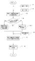
- the display as shown in FIG. 4 is convenient in terms of the design of the knitted fabric, but when actually knitting the knitted fabric, the knitting of a different gauge region having stitches having a size different from the initial gauge region is performed. It is necessary to create a knitting program that reflects how the different gauge region and the initial gauge region are joined. Therefore, the knitted fabric design system 100 according to the present invention determines the knitting method in the different gauge area by the different gauge area knitting setting unit 51 provided in the pattern data editing means 5 and the boundary area knitting provided in the pattern data editing means 5. The setting unit 52 determines the knitting method at the boundary between the different gauge region and the initial gauge region, and the knitting program creating means 8 creates a knitting program based on these pieces of information. In the following, referring to the block diagram of FIG.
- the different gauge region knitting setting unit 51 acquires initial gauge information including an initial gauge knitting unit and different gauge information including a different gauge knitting unit and a different gauge knitting region (steps 1 and 2).
- the initial gauge information and the different gauge information may be those already input to the pattern data editing means 5 when the different gauge area is set in the pattern data composed of the initial gauge knitting unit.
- the different gauge region knitting setting unit 51 specifies the number and position information of the different gauge knitting units in the different gauge region from the initial gauge information and the different gauge information (step 3).
- the different gauge area knitting setting unit 51 determines how to perform knitting in the different gauge area. For example, it is determined whether the difference in size between the initial gauge knitting unit and the different gauge knitting unit is a predetermined value or more (step 4), and the knitting in step 5-1 described below is performed, or the knitting in step 5-2 is performed. Decide whether or not to perform.
- the predetermined value may be a fixed value that is input in advance, or may be a correction value that is automatically corrected with reference to information relating to knitting such as the thickness of the knitting yarn, and can be changed by the operator. You may do it. Further, without providing this step 4, it may be configured to shift directly from step 3 to step 5-1 or step 5-2 described below.
- the different gauge area knitting setting unit 51 adjusts the number of knitting needles used to execute the knitting code set in the different gauge knitting unit to thereby create stitches in the different gauge area.
- a knitting for adjusting the size of the knives is set (step 5-1). Taking FIG. 4 as an example, the size of the different gauge knitting units corresponds to exactly four initial gauge knitting units. Therefore, for example, as shown in FIG. 5 referred to in the description of the prior art, the different gauge knitting units are disassembled into four knitting units, and knits and mistakes are distributed to the lower two knitting units (first course). The size of the stitches in the different gauge area is secured, and two mistakes are set in the upper two knitting units (second course).
- four knitting needles are used to execute the knit knitting code set in the different gauge knitting unit.
- a knit knitting code is set for the initial gauge knitting unit in the initial gauge region, one knitting needle is used to execute the knit knitting code. For example, if total needle knitting is performed in the initial gauge region, the knitting method is changed so that needle knitting is performed in the different gauge region.
- the different gauge knitting unit is larger than the initial gauge knitting unit, but in the opposite case, in order to execute the knitting code set in the different gauge knitting unit.
- the number of knitting needles to be used may be smaller than the number of knitting needles used in the initial gauge knitting unit in which the same knitting code is set. For example, when the initial gauge area is knitted without needles, to make a stitch in the initial gauge knitting unit, two knitting needles that make a knit and a mistake are used, whereas in the different gauge area, the total needle knitting can be performed. It ’s fine.
- the different gauge area knitting setting unit 51 changes the loop length of the stitch of the different gauge knitting unit in order to execute the knitting code set in the different gauge knitting unit.
- a knitting for adjusting the size of the stitch is set (step 5-2).
- the loop length of the stitch can be changed by adjusting the pull-in amount of the knitting needle when making the stitch. For example, when the different gauge knitting unit is larger than the initial gauge knitting unit, the knitting needle pull-in amount is increased, and when the different gauge knitting unit is smaller than the initial gauge knitting unit, the knitting needle pull-in amount is decreased.
- the boundary region knitting setting unit 52 of the pattern data editing means 5 calls the knitting method data of the boundary portion (step 6), and the boundary portion between the initial gauge region and the different gauge region
- the knitting method is determined (step 7).
- the boundary knitting method data is a collection of known knitting methods stored in storage means (not shown) in the knitted fabric design system 100.
- the boundary region knitting setting unit 52 includes initial gauge information, An optimum knitting method is determined from a group of knitting methods with reference to the gauge information and the knitting method of different gauge regions. Usually, the initial gauge region and the different gauge region have different numbers of stitches at the upper and lower boundary portions arranged in the wale direction of both regions, and therefore, the knitting method is mainly selected so that these numbers are matched.
- the size of the different gauge knitting units in the course direction is two initial gauge knitting units. Therefore, at the lower boundary portion where the initial gauge region changes to the different gauge region, for example, two adjacent stitches in the stitch row of the initial gauge region arranged in the boundary portion are overlapped to form the course of the different gauge region. Double stitches are formed so as to match the number of stitches in the direction, and stitches in different gauge regions are knitted on these double stitches. In addition, at the upper boundary where the different gauge region changes from the initial gauge region, for example, the stitches in the stitch row of the different gauge region aligned with the boundary are increased to match the number of stitches in the initial gauge region, The stitches in the initial gauge area are knitted on these split stitches. When the size difference between the different gauge region and the initial gauge region is very small, the number of stitches arranged in the boundary portion in the initial gauge region and the different gauge region may be the same. It is not necessary to adjust the number of stitches.
- the initial gauge area and the different gauge area may differ in the number of courses at the boundary in the course direction of both areas.
- the boundary region knitting setting unit 52 selects a knitting method of the boundary portion so that the knitted fabric is not pulled or slack due to the difference in the number of courses. It is determined how many courses the initial gauge and the different gauge area are connected to each other according to the ratio of the initial gauge area and the different gauge area. In the case shown in FIG. 4, the connection of one course in the different gauge region is made to two courses in the initial gauge region.
- the knitting program creation means 8 sets the actual operation of the knitting needle and the knitting yarn feeding procedure based on the knitting code.
- a program is created (step 8).
- the created knitting program is sent to a flat knitting machine via a recording medium such as a magnetic disk, wired or wireless.
- FIG. 2 illustrates the relationship between the initial gauge region and the different gauge region as an example.
- the knitting method in the different gauge region and the knitting method in the boundary portion where the gauge is different are shown in this flowchart. If the concept for determination is used, two or more different gauge regions different from the initial gauge region can be set.
- the knitting method in the different gauge region may be determined based on the initial gauge knitting unit. Further, the knitting method at the boundary portion where the gauges are different may be determined based on the initial gauge knitting unit.
- the knitting method at the boundary between one different gauge region and the initial gauge region is determined based on the initial gauge knitting unit, one different gauge region and the other
- the knitting method at the boundary with the different gauge region is also indirectly determined based on the initial gauge knitting unit.
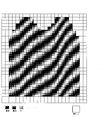
- the processing described above is executed inside the pattern data editing means 5 and differs from the initial gauge as shown in FIG. Pattern data having a gauge (multiple gauge pattern data) is displayed, but the pattern data editing means 5 has pattern data (single gauge pattern data) represented by a single gauge as shown in FIG. ) Data exists.
- the display processing means 6 is instructed to switch between the display with a plurality of gauges and the display with a single gauge by a display switching command means (not shown) (for example, an icon or a keyboard displayed on the display means 7).
- a display switching command means not shown
- the display processing means 6 may be operated so as to simultaneously display with a plurality of gauges and display with a single gauge.
- the display since the knitting program has been created, the display may be switched to the knitting program display.
- the knitted fabric design system of the present invention can be suitably used for knitting knitted fabrics having various organizational patterns in which a plurality of gauges are mixed.
Landscapes
- Engineering & Computer Science (AREA)
- Textile Engineering (AREA)
- Knitting Machines (AREA)
Abstract
ゲージの異なる領域を有する編地を容易にデザインすることができる編地のデザインシステムを提供する。編地をデザインするにあたり設定した初期ゲージ情報とは異なるゲージでの編成に関する異ゲージ情報を設定する異ゲージ情報設定手段3と、初期ゲージ情報と異ゲージ情報に基づいてゲージの異なる複数の編成単位を有する複数ゲージ柄データを作成し、この複数ゲージ柄データにおける各編成単位に編成コードを割り当てることができるように複数ゲージ柄データを編集する柄データ編集手段5と、複数ゲージ柄データの編集状態を表示手段7に表示させる表示処理手段6と、複数ゲージ柄データの各編成単位に割り当てられた編成コードに基づいて編地の編成プログラムを作成する編成プログラム作成手段8とを備える。
Description
本発明は、ゲージの異なる編目が混在した編地をデザインするための編地のデザインシステムに関する。
従来から、モニター上で編地をデザインするシステムが提案されている(例えば、特許文献1を参照)。このシステムでは、まず、編地の外形寸法を決定してシステム上に型紙を形成し、次いで、編地の縦方向(ウェール方向)および横方向(コース方向)の所定長さ当たり(例えば、10cm)の目数であるゲージを決定して、ゲージに基づいた編成単位を型紙に割り当てた柄データを作成する。そして、このシステムでは、柄データに配列される編成単位に対してどのような編成動作を行うかを規定した編成コードを当てはめることで、編地のデザインを行っている。また、このシステムでは、実際の編目の縦横比を反映した編成単位をモニター上に表示することで、出来上がりの状態を想定したデザインを行い易いようにしている。
ところで、編地のファッション性を高めるために、大きさの異なる編目が混在した編地、即ち、ゲージの異なる領域が混在した編地を編成したいというニーズがあった。これに対して、上述した特許文献1のシステムを含め、柄データの作成時に設定した初期ゲージと異なるゲージを柄データに組み込むシステムはなかった。そのため、編地に対して異ゲージでの編成領域を設ける場合、当該領域で編目が所望の大きさになるようにシステム操作者が編成単位に編成コードを配置する以外に方法がなかった。例えば、図5に示すように、異ゲージでの編成領域を想定した場合、図面下部から編成を実施していき、異ゲージでの編成領域に差しかかったときにニット(表目)の編成コードとミスの編成コードを組み合わせた針抜き編成をして編目のループ長を長くし、さらに針抜き編成の上の編成コースでは、長くしたループ長の分だけミスの編成コードを指定していた。つまり、このような方法では、実際の編地では一つの編目からなる部分であるにも拘らず、モニター上ではニットの編成コードが1つとミスの編成コードが3つ配置されており、モニター上で編地の出来上がり状態を想定し難いという問題があった。
本発明は、上記事情に鑑みてなされたものであり、ゲージの異なる領域を有する編地を容易にデザインすることができる編地のデザインシステムを提供することを目的とする。
本発明の編地のデザインシステムは、編地の縦方向および横方向の所定長さ当たりの目数であるゲージを指定することで、ゲージに対応した編成単位を決定すると共に、編地の型紙を編成単位からなる柄データに変換して表示手段に表示し、横編機における編成動作を指定する編成コードを前記編成単位に配列することで編地のデザインをコンピュータ上で行う。この編地のデザインシステムは、編地をデザインするにあたり設定した初期ゲージ情報とは異なるゲージでの編成に関する異ゲージ情報を設定する異ゲージ情報設定手段と、初期ゲージ情報と異ゲージ情報に基づいてゲージの異なる複数の編成単位を有する複数ゲージ柄データを作成し、この複数ゲージ柄データにおける各編成単位に編成コードを割り当てることができるように複数ゲージ柄データを編集する柄データ編集手段と、複数ゲージ柄データの編集状態を表示手段に表示させる表示処理手段と、複数ゲージ柄データの各編成単位に割り当てられた編成コードに基づいて編地の編成プログラムを作成する編成プログラム作成手段とを備える。
本発明の一形態として、柄データ編集手段は、異なる編成単位で編成される領域同士の境界部における編目の編成方法を決定する境界領域編成設定部を有していても良い。
また、本発明の一形態として、柄データ編集手段は、初期ゲージでの編成単位と異ゲージでの編成単位とのサイズの相違に応じて、異ゲージ領域での編目の編成方法を決定する異ゲージ領域編成設定部を有していても良い。
さらに、本発明の一形態として、柄データ編集手段は、複数ゲージ柄データを単一の編成単位からなる単一ゲージ柄データに変換するようにしても良い。そして、表示処理手段は、複数ゲージ柄データと単一ゲージ柄データとを切り替え可能に表示手段に表示させるようにする。
本発明の構成によれば、表示手段上にゲージの異なる複数の編成単位からなる複数ゲージ柄データが表示され、これら編成単位のそれぞれに対して編成コードを割り当てることができるので、編地の出来上がり状態を想定しつつ編地のデザインを行うことができる。
境界領域編成設定部を備えることにより、異なる編成単位間の境界部を違和感なく仕上げるための編成方法の決定を編地のデザインシステムに行わせることができる。そのため、従来であれば操作者が行っていた境界部における編成コードの設定の手間を省くことができる。
異ゲージ領域編成設定部を備えることにより、異ゲージ領域における編目の編成方法の決定を編地のデザインシステムに行わせることができる。そのため、従来であれば操作者が行っていた異ゲージでの編成領域における編成コードの設定の手間を省くことができる。
複数ゲージ柄データと、複数ゲージ柄データを単一のゲージでの表現に変換した単一ゲージ柄データとを同時にあるいは切り替え可能に表示することにより、効率的な編地のデザインを行うことができる。複数ゲージ柄データが表示手段に表示された状態であれば、編地の出来上がりを想定しつつ編地をデザインすることができる。また、この複数ゲージ柄データを単一ゲージ柄データに切り替えれば、実際の編地の編み上がり具合を良くするために編地の編成方法を容易に微調整することができる。
100 編地のデザインシステム
1 型紙情報設定手段
2 初期ゲージ設定手段
3 異ゲージ情報設定手段
31 異ゲージ設定手段 32 異ゲージ領域設定手段
4 編成単位算出手段
5 柄データ編集手段
51 異ゲージ領域編成設定部 52 境界領域編成設定部
6 表示処理手段 7 表示手段
8 編成プログラム作成手段
9 編成コード設定手段 10 編成コード記憶手段
1 型紙情報設定手段
2 初期ゲージ設定手段
3 異ゲージ情報設定手段
31 異ゲージ設定手段 32 異ゲージ領域設定手段
4 編成単位算出手段
5 柄データ編集手段
51 異ゲージ領域編成設定部 52 境界領域編成設定部
6 表示処理手段 7 表示手段
8 編成プログラム作成手段
9 編成コード設定手段 10 編成コード記憶手段
以下、本発明の実施形態を図に基づいて説明する。なお、図3~5において、紙面左右方向(横方向)をコース方向、紙面上下方向(縦方向)をウェール方向とする。
図1は、本発明の編地のデザインシステムを示すブロック図である。編地のデザインシステム100は、編地をデザインするにあたって種々の設定を入力するための設定手段を備える。設定手段としては、型紙情報設定手段1と、初期ゲージ設定手段2と、異ゲージ情報設定手段3と、編成コード設定手段9とが挙げられ、例えば、キーボードやデジタイザなどの形態で構成される。また、編地のデザインシステムは、柄データ編集手段5と、表示処理手段6と、表示手段7(例えば、モニター)と、編成プログラム作成手段8とを備える。柄データ編集手段5は、上記各設定手段からの入力情報に基づいてゲージの異なる複数の編成単位を有する複数ゲージ柄データを作成し、複数ゲージ柄データにおける各編成単位に編成コードを割り当てることができるように複数ゲージ柄データを編集する。また、表示処理手段6は、複数ゲージ柄データを、異なるゲージに基づいて決定された編成単位が混在した状態のまま表示手段7に表示させる。さらに、編成プログラム作成手段8は、複数ゲージ柄データの各編成単位に割り当てられた編成コードに基づいて編地を編成するための編成プログラムを作成する。以下、この編地のデザインシステムを利用した編地のデザインの一例を示すことで、各手段についても詳細に説明する。
まず、型紙情報設定手段1により実際の編地の寸法、即ち、型紙の形状や寸法を入力する。型紙の情報は、後述する編成単位算出手段4と柄データ編集手段5とに出力される。次いで、初期ゲージ設定手段2により編地の縦方向および横方向の所定長さ当たりの編目数である初期ゲージを設定する。設定された初期ゲージは、編成単位算出手段4に入力される。これら型紙情報設定手段1と初期ゲージ設定手段2としては、表示手段7に表示されるダイアログボックスにキーボードから数値を入力する構成が一般的である。
編成単位算出手段4は、入力された初期ゲージと型紙の情報から、編地に対する一目の大きさ、即ち、初期ゲージ編成単位の大きさを算出し、柄データ編集手段5に出力する。柄データ編集手段5は、型紙を初期ゲージ編成単位からなる柄データに変換し、表示処理手段6に出力する。表示処理手段6は、柄データに初期ゲージ編成単位が並んだ状態を表示手段7に表示させる。ここで、表示処理手段6は、特許文献1に記載のように、実際の編目の縦横比を反映した形状を有する初期ゲージ編成単位を作成し、表示手段7に表示させるようにすることが好ましい。
型紙の初期ゲージ編成単位でどのような編成を行わせるかについては、初期ゲージ編成単位に編成コードを配置するための編成コード設定手段9を用いる。編成コードは、ニットやタック、ミスなどの編成動作を、例えば、色や数字、図形あるいはこれらの組み合わせにより表現したものであり、編成コード記憶手段10に記憶されている。初期ゲージ編成単位に編成コードを配置することで、柄データ編集手段5の内部で初期ゲージ編成単位での編成動作を規定でき、表示手段7上ではその編成動作を把握できる。例示として、初期ゲージ編成単位に全て表目を配置した状態を図3に示す。
初期ゲージの設定をした後に、本発明の編地のデザインシステム100では、初期ゲージと異なるゲージ(異ゲージ)を有する異ゲージ領域を柄データ(初期ゲージ領域)内に設定することができる。具体的には、まず、異ゲージ情報設定手段3の異ゲージ設定手段31により異ゲージ領域でのゲージの値を設定する。異ゲージ設定手段31での設定は編成単位算出手段4に入力され、異ゲージ領域での編成単位(異ゲージ編成単位)が算出される。異ゲージ編成単位が決定されると、異ゲージ領域設定手段32により、異ゲージ設定手段31で設定したゲージで編成される異ゲージ領域を柄データ内に指定することができる。例えば、図4に示すように、異ゲージでの編成領域を指定するためのアイコンを表示させ、このアイコンをクリックすることで異ゲージ領域設定モードに切り替え、表示手段7上のポインタで異ゲージ領域の始点と、この始点と対角位置にある終点とを決定することで異ゲージ領域を指定する構成とすることが挙げられる。異ゲージ編成単位や異ゲージ領域の位置情報などの異ゲージ情報は、柄データ編集手段5により型紙に反映され、初期編成単位と異ゲージ編成単位とを有する柄データ(複数ゲージ柄データ)が、表示処理手段6を介して表示手段7に表示される。例えば、初期ゲージに対して縦方向2倍、横方向2倍の異ゲージを設定した場合、図4に示すように、異ゲージ編成単位を示すアイコンが、初期ゲージ編成単位の4倍の大きさを有するように表示される。この異ゲージ編成単位に対しても、初期ゲージ編成単位と同様に、編成コード設定手段9での編成コードの割り当てが可能である。そのため、表示手段7上で異ゲージ領域に対してどのような編成が行われるかについて把握することができ、編地の出来上がり状態を想定した編地のデザインを容易に行うことができる。
ここで、図4のような表示は、編地のデザイン上は便利であるが、実際に編地を編成する際は、初期ゲージ領域とは異なる大きさの編目を持つ異ゲージ領域の編成をどのように行うのか、異ゲージ領域と初期ゲージ領域との接合をどのように行うのかを反映させた編成プログラムを作成しなければならない。そこで、本発明の編地のデザインシステム100は、柄データ編集手段5に備わる異ゲージ領域編成設定部51により異ゲージ領域での編成方法を決定すると共に、柄データ編集手段5に備わる境界領域編成設定部52により異ゲージ領域と初期ゲージ領域との境界部における編成方法を決定し、これらの情報に基づいて編成プログラム作成手段8により編成プログラムを作成する。以下、図4に示すように異ゲージ編成単位にニット(表目)の編成コードを割り当てた場合を例にして、編成プログラムの作成手順を図1のブロック図と図2のフローチャートを参照して説明する。
まず、異ゲージ領域編成設定部51は、初期ゲージ編成単位を含む初期ゲージ情報と、異ゲージ編成単位および異ゲージ編成領域を含む異ゲージ情報とを取得する(ステップ1および2)。初期ゲージ情報と異ゲージ情報とは、初期ゲージ編成単位からなる柄データに異ゲージ領域を設定した際に既に柄データ編集手段5に入力されているものを使用すれば良い。次いで、異ゲージ領域編成設定部51は、初期ゲージ情報と異ゲージ情報から、異ゲージ領域における異ゲージ編成単位の数と位置情報を特定する(ステップ3)。
異ゲージ編成単位の数と位置情報を特定すれば、異ゲージ領域編成設定部51は、異ゲージ領域での編成をどのように行うのかを決定する。例えば、初期ゲージ編成単位と異ゲージ編成単位とのサイズの相違が所定値以上であるかを判断し(ステップ4)、次述するステップ5-1の編成を行なうか、ステップ5-2の編成を行なうのかを決定する。この所定値は、予め入力された固定値としても良いし、この固定値を編糸の太さなどの編成に関する情報を参照して自動で補正した補正値としても良いし、操作者が変更できるようにしても良い。また、このステップ4を設けずに、ステップ3から直接、次述するステップ5-1もしくはステップ5-2に移行するように構成してもかまわない。
サイズ差が所定値以上であれば、異ゲージ領域編成設定部51は、異ゲージ編成単位に設定された編成コードを実行するために使用する編針の数を調節することで異ゲージ領域での編目の大きさを調節する編成を設定する(ステップ5-1)。図4を例にすれば、異ゲージ編成単位の大きさが初期ゲージ編成単位のちょうど4つ分に相当する。そこで、例えば、従来技術の説明で参照した図5のように、異ゲージ編成単位を4つの編成単位に分解し、下段の2つ(1コース目)の編成単位にニットとミスを振り分けて、異ゲージ領域での編目の大きさを確保し、上段の2つ(2コース目)の編成単位に2つのミスを設定する。つまり、異ゲージ編成単位に設定されたニットの編成コードを実行するために4本の編針が使用されている。これに対して、初期ゲージ領域の初期ゲージ編成単位にニットの編成コードを設定すれば、ニットの編成コードを実行するために使用される編針は1本である。例えば、初期ゲージ領域で総針編成をしていれば、異ゲージ領域では針抜き編成となるように編成方法を変更する。
ここで、図4を参照した説明では初期ゲージ編成単位よりも異ゲージ編成単位の方が大きい場合であったが、その逆の場合、異ゲージ編成単位に設定された編成コードを実行するために使用する編針の数を、同じ編成コードが設定された初期ゲージ編成単位で使用する編針の数よりも少なくすれば良い。例えば、初期ゲージ領域が針抜き編成されている場合、初期ゲージ編成単位で編目を作るには、ニットとミスをする2つの編針を使用するのに対して、異ゲージ領域では総針編成を行なえば良い。
一方、サイズ差が所定値未満であれば、異ゲージ領域編成設定部51は、異ゲージ編成単位に設定された編成コードを実行するために異ゲージ編成単位の編目のループ長を変更することで編目の大きさを調節する編成を設定する(ステップ5-2)。代表的には、編目を作る際に編針の引き込み量を調節することで編目のループ長を変更することができる。例えば、初期ゲージ編成単位よりも異ゲージ編成単位が大きい場合は、編針の引き込み量を大きくし、初期ゲージ編成単位よりも異ゲージ編成単位が小さい場合は、編針の引き込み量を小さくする。
異ゲージ領域の編成方法が決定されれば、柄データ編集手段5の境界領域編成設定部52は、境界部の編成方法データを呼び出し(ステップ6)、初期ゲージ領域と異ゲージ領域との境界部分における編成方法を決定する(ステップ7)。境界部の編成方法データは、編地のデザインシステム100内の記憶手段(図示せず)に記憶される公知の編成方法の集合体であり、境界領域編成設定部52は、初期ゲージ情報、異ゲージ情報および異ゲージ領域の編成方法を参照して、編成方法の集合体のなかから最適な編成方法を決定する。通常、初期ゲージ領域と異ゲージ領域は、両領域のウェール方向に並ぶ上下の境界部における編目の数が異なるため、主として、これらの数を一致させておくような編成方法が選択される。例えば、図4の場合、異ゲージ編成単位のコース方向の大きさは、初期ゲージ編成単位の2つ分である。従って、初期ゲージ領域から異ゲージ領域に変化する下側の境界部では、例えば、境界部に並ぶ初期ゲージ領域の編目列のうち、隣接する2つの編目同士を重ね合わせて、異ゲージ領域のコース方向の編目数と一致するようにした重ね目を形成し、これら重ね目の上に異ゲージ領域の編目を編成する。また、異ゲージ領域から初期ゲージ領域に変化する上側の境界部では、例えば、境界部に並ぶ異ゲージ領域の編目列の編目を割り増やしして、初期ゲージ領域の編目数と一致するようにし、これら割り増やし目の上に初期ゲージ領域の編目を編成する。なお、異ゲージ領域と初期ゲージ領域とのサイズ差が非常に小さい場合は、初期ゲージ領域と異ゲージ領域とで境界部に並ぶ編目の数が同じこともあり得るので、そのときは、境界部における編目数の調節をしなければ良い。
さらに、初期ゲージ領域と異ゲージ領域は、両領域のコース方向の境界部におけるコースの数が異なることもある。そのときは、境界領域編成設定部52は、コース数の相違により編地に引きつれやたるみなどが生じないような境界部の編成方法を選択する。初期ゲージ領域と異ゲージ領域との比率に応じて初期ゲージと異ゲージ領域とを何コース毎に接続するかを決定する。図4に示す場合では、初期ゲージ領域2コースに対して異ゲージ領域1コースの接続を行う。
異ゲージ領域での編成方法と、ゲージの異なる境界部における編成方法が決定したら、編成プログラム作成手段8は、この編成コードに基づいて実際の編針の動作および編糸の繰り出し手順などを設定した編成プログラムを作成する(ステップ8)。作成した編成プログラムは、磁気ディスクなどの記録媒体や、有線、無線などを介して横編機へ送られる。
なお、上述した図2のフローチャートは、初期ゲージ領域と異ゲージ領域との関係を例として挙げているが、このフローチャートに示す異ゲージ領域での編成方法とゲージの異なる境界部での編成方法を決定するための考え方を利用すれば、初期ゲージ領域とは異なる2つ以上の異ゲージ領域を設定することもできる。異ゲージ領域での編成方法は、あくまで初期ゲージ編成単位を基準として決定すれば良い。また、ゲージの異なる境界部における編成方法も初期ゲージ編成単位を基準として決定すれば良い。例えば、ゲージの異なる異ゲージ領域が隣接する場合でも、一方の異ゲージ領域と初期ゲージ領域との境界部の編成方法が初期ゲージ編成単位を基準として決定されれば、一方の異ゲージ領域と他方の異ゲージ領域との境界部の編成方法も間接的に初期ゲージ編成単位を基準に決定される。
以上説明した処理は、柄データ編集手段5の内部で実行されており、出来上がりを想定して編地をデザインし易くするために、表示手段7上ではあくまで図4に示すような初期ゲージと異ゲージとを有する柄データ(複数ゲージ柄データ)が表示されているが、柄データ編集手段5の内部には、図5に示すような単一ゲージで表される柄データ(単一ゲージ柄データ)のデータが存在する。本実施形態では、図示しない表示切り替え指令手段(例えば、表示手段7に表示されるアイコンや、キーボード)により、複数ゲージでの表示と単一ゲージでの表示との切り替えを表示処理手段6に指令するように構成する。もちろん、複数ゲージでの表示と単一ゲージでの表示を同時に行うように表示処理手段6を操作してもかまわない。また、編成プログラムが作成されているので、編成プログラムの表示に切り替えられるようにしても良い。
なお、上述した実施の形態は、あくまで一例であって、本発明の要旨を逸脱しない範囲において適宜変更することができる。
本発明の編地のデザインシステムは、複数ゲージが混在した多様な組織柄を有する編地の編成に好適に利用可能である。
Claims (4)
- 編地の縦方向および横方向の所定長さ当たりの目数であるゲージを指定することで、ゲージに対応した編成単位を決定すると共に、編地の型紙を編成単位からなる柄データに変換して表示手段に表示し、横編機における編成動作を指定する編成コードを前記編成単位に配列することで編地のデザインをコンピュータ上で行うための編地のデザインシステムであって、
編地をデザインするにあたり設定した初期ゲージ情報とは異なるゲージでの編成に関する異ゲージ情報を設定する異ゲージ情報設定手段と、
初期ゲージ情報と異ゲージ情報に基づいてゲージの異なる複数の編成単位を有する複数ゲージ柄データを作成し、この複数ゲージ柄データにおける各編成単位に編成コードを割り当てることができるように複数ゲージ柄データを編集する柄データ編集手段と、
複数ゲージ柄データの編集状態を表示手段に表示させる表示処理手段と、
複数ゲージ柄データの各編成単位に割り当てられた編成コードに基づいて編地の編成プログラムを作成する編成プログラム作成手段とを備えることを特徴とする編地のデザインシステム。 - 柄データ編集手段は、異なる編成単位で編成される領域同士の境界部における編目の編成方法を決定する境界領域編成設定部を有することを特徴とする請求項1に記載の編地のデザインシステム。
- 柄データ編集手段は、初期ゲージでの編成単位と異ゲージでの編成単位とのサイズの相違に応じて、異ゲージ領域での編目の編成方法を決定する異ゲージ領域編成設定部を有することを特徴とする請求項1または2に記載の編地のデザインシステム。
- 柄データ編集手段は、複数ゲージ柄データを単一の編成単位からなる単一ゲージ柄データに変換し、
表示処理手段は、複数ゲージ柄データと単一ゲージ柄データとを切り替え可能に表示手段に表示させることを特徴とする請求項1~3のいずれか一項に記載の編地のデザインシステム。
Priority Applications (3)
| Application Number | Priority Date | Filing Date | Title |
|---|---|---|---|
| CN200980106222.9A CN101952497B (zh) | 2008-03-12 | 2009-03-06 | 针织物设计系统 |
| EP09719046.6A EP2273002B1 (en) | 2008-03-12 | 2009-03-06 | Knitted fabric designing system |
| JP2010502715A JP5161297B2 (ja) | 2008-03-12 | 2009-03-06 | 編地のデザインシステム |
Applications Claiming Priority (2)
| Application Number | Priority Date | Filing Date | Title |
|---|---|---|---|
| JP2008062406 | 2008-03-12 | ||
| JP2008-062406 | 2008-03-12 |
Publications (1)
| Publication Number | Publication Date |
|---|---|
| WO2009113282A1 true WO2009113282A1 (ja) | 2009-09-17 |
Family
ID=41064956
Family Applications (1)
| Application Number | Title | Priority Date | Filing Date |
|---|---|---|---|
| PCT/JP2009/001014 Ceased WO2009113282A1 (ja) | 2008-03-12 | 2009-03-06 | 編地のデザインシステム |
Country Status (4)
| Country | Link |
|---|---|
| EP (1) | EP2273002B1 (ja) |
| JP (1) | JP5161297B2 (ja) |
| CN (1) | CN101952497B (ja) |
| WO (1) | WO2009113282A1 (ja) |
Cited By (6)
| Publication number | Priority date | Publication date | Assignee | Title |
|---|---|---|---|---|
| WO2011065263A1 (ja) * | 2009-11-26 | 2011-06-03 | 株式会社島精機製作所 | ニットデザイン装置とデザイン方法、デザインプログラム |
| DE102010053862A1 (de) * | 2010-12-08 | 2012-06-14 | H. Stoll Gmbh & Co. Kg | Simultane Gestricksimulation während der Mustererstellung anhand einer komprimirten Symboldarstellung |
| KR20150108770A (ko) * | 2014-03-18 | 2015-09-30 | 가부시키가이샤 시마세이키 세이사쿠쇼 | 니트 디자인 시스템과 니트 디자인 방법 |
| JP2015175083A (ja) * | 2014-03-18 | 2015-10-05 | 株式会社島精機製作所 | ニットデザインシステムとニットデザイン方法 |
| JP2016003403A (ja) * | 2014-06-13 | 2016-01-12 | 株式会社島精機製作所 | 編地のデザインシステム |
| US20230147207A1 (en) * | 2021-11-09 | 2023-05-11 | Shanghai Cimpress Technology Company Limited | Method and apparatus for customizing knitted products |
Families Citing this family (2)
| Publication number | Priority date | Publication date | Assignee | Title |
|---|---|---|---|---|
| JP5980273B2 (ja) * | 2014-07-14 | 2016-08-31 | 株式会社島精機製作所 | 縄柄の編成方法、編地のデザインシステム、および記憶媒体 |
| CN108960381A (zh) * | 2018-06-08 | 2018-12-07 | 北京三快在线科技有限公司 | 标识编织方法、装置、电子设备、存储介质及编织标识 |
Citations (8)
| Publication number | Priority date | Publication date | Assignee | Title |
|---|---|---|---|---|
| JPH0321661B2 (ja) * | 1983-09-27 | 1991-03-25 | Shima Seiki Mfg | |
| JPH0770889A (ja) | 1993-08-31 | 1995-03-14 | Shima Seiki Mfg Ltd | ニットペイントシステム |
| JPH07140893A (ja) * | 1993-11-18 | 1995-06-02 | Sanyo Electric Co Ltd | 料理教示装置及び編物教示装置 |
| JPH0841773A (ja) * | 1994-07-27 | 1996-02-13 | Shima Seiki Mfg Ltd | ニット製品への刺繍方法及び刺繍cad装置 |
| JP2656405B2 (ja) * | 1991-09-17 | 1997-09-24 | 旭化成工業株式会社 | ニットデザインシステムおよびその編成データの作成方法 |
| JP2001003247A (ja) * | 1999-06-17 | 2001-01-09 | Tsudakoma Corp | 横編み機における編み糸量制御方法及び装置 |
| US6611730B1 (en) * | 1999-01-16 | 2003-08-26 | H. Stoll Gmbh & Co. | Device and method of designing knit products to be manufactured on a knitting machine |
| WO2007058123A1 (ja) * | 2005-11-17 | 2007-05-24 | Shima Seiki Manufacturing, Ltd. | ニットデザイン装置とニットデザイン方法及びそのプログラム |
Family Cites Families (2)
| Publication number | Priority date | Publication date | Assignee | Title |
|---|---|---|---|---|
| DE3812488A1 (de) * | 1988-04-15 | 1989-11-02 | Stoll & Co H | Flachstrickmaschine |
| DE4431898A1 (de) * | 1994-09-07 | 1996-03-14 | Scheller Gmbh | Einrichtung zur Entwicklung eines Steuerprogramms für eine Strick- oder Wirkmaschine |
-
2009
- 2009-03-06 WO PCT/JP2009/001014 patent/WO2009113282A1/ja not_active Ceased
- 2009-03-06 CN CN200980106222.9A patent/CN101952497B/zh not_active Expired - Fee Related
- 2009-03-06 EP EP09719046.6A patent/EP2273002B1/en not_active Not-in-force
- 2009-03-06 JP JP2010502715A patent/JP5161297B2/ja not_active Expired - Fee Related
Patent Citations (9)
| Publication number | Priority date | Publication date | Assignee | Title |
|---|---|---|---|---|
| JPH0321661B2 (ja) * | 1983-09-27 | 1991-03-25 | Shima Seiki Mfg | |
| JP2656405B2 (ja) * | 1991-09-17 | 1997-09-24 | 旭化成工業株式会社 | ニットデザインシステムおよびその編成データの作成方法 |
| JPH0770889A (ja) | 1993-08-31 | 1995-03-14 | Shima Seiki Mfg Ltd | ニットペイントシステム |
| JP2741473B2 (ja) * | 1993-08-31 | 1998-04-15 | 株式会社島精機製作所 | ニットペイントシステム |
| JPH07140893A (ja) * | 1993-11-18 | 1995-06-02 | Sanyo Electric Co Ltd | 料理教示装置及び編物教示装置 |
| JPH0841773A (ja) * | 1994-07-27 | 1996-02-13 | Shima Seiki Mfg Ltd | ニット製品への刺繍方法及び刺繍cad装置 |
| US6611730B1 (en) * | 1999-01-16 | 2003-08-26 | H. Stoll Gmbh & Co. | Device and method of designing knit products to be manufactured on a knitting machine |
| JP2001003247A (ja) * | 1999-06-17 | 2001-01-09 | Tsudakoma Corp | 横編み機における編み糸量制御方法及び装置 |
| WO2007058123A1 (ja) * | 2005-11-17 | 2007-05-24 | Shima Seiki Manufacturing, Ltd. | ニットデザイン装置とニットデザイン方法及びそのプログラム |
Non-Patent Citations (2)
| Title |
|---|
| FUJITSU S: "Family Designer's Workbench Knit Module Shiyo Tebikisho (Textile Designer Shien System), 1st edition", FUJITSU ESU E SHISUTEMUZU KABUSHIKI KAISHA, 31 July 1995 (1995-07-31), pages 47 - 48, XP008145963 * |
| See also references of EP2273002A4 * |
Cited By (10)
| Publication number | Priority date | Publication date | Assignee | Title |
|---|---|---|---|---|
| WO2011065263A1 (ja) * | 2009-11-26 | 2011-06-03 | 株式会社島精機製作所 | ニットデザイン装置とデザイン方法、デザインプログラム |
| KR101356987B1 (ko) | 2009-11-26 | 2014-01-29 | 가부시키가이샤 시마세이키 세이사쿠쇼 | 니트 디자인 장치와 디자인 방법, 디자인 프로그램 |
| DE102010053862A1 (de) * | 2010-12-08 | 2012-06-14 | H. Stoll Gmbh & Co. Kg | Simultane Gestricksimulation während der Mustererstellung anhand einer komprimirten Symboldarstellung |
| KR20150108770A (ko) * | 2014-03-18 | 2015-09-30 | 가부시키가이샤 시마세이키 세이사쿠쇼 | 니트 디자인 시스템과 니트 디자인 방법 |
| JP2015175082A (ja) * | 2014-03-18 | 2015-10-05 | 株式会社島精機製作所 | ニットデザインシステムとニットデザイン方法 |
| JP2015175083A (ja) * | 2014-03-18 | 2015-10-05 | 株式会社島精機製作所 | ニットデザインシステムとニットデザイン方法 |
| KR101690526B1 (ko) * | 2014-03-18 | 2016-12-28 | 가부시키가이샤 시마세이키 세이사쿠쇼 | 니트 디자인 시스템과 니트 디자인 방법 |
| JP2016003403A (ja) * | 2014-06-13 | 2016-01-12 | 株式会社島精機製作所 | 編地のデザインシステム |
| US20230147207A1 (en) * | 2021-11-09 | 2023-05-11 | Shanghai Cimpress Technology Company Limited | Method and apparatus for customizing knitted products |
| US12060664B2 (en) * | 2021-11-09 | 2024-08-13 | Shanghai Cimpress Technology Company Limited | Method and apparatus for customizing knitted products |
Also Published As
| Publication number | Publication date |
|---|---|
| EP2273002B1 (en) | 2016-04-27 |
| JPWO2009113282A1 (ja) | 2011-07-21 |
| EP2273002A1 (en) | 2011-01-12 |
| CN101952497B (zh) | 2012-06-20 |
| JP5161297B2 (ja) | 2013-03-13 |
| EP2273002A4 (en) | 2015-03-18 |
| CN101952497A (zh) | 2011-01-19 |
Similar Documents
| Publication | Publication Date | Title |
|---|---|---|
| JP5161297B2 (ja) | 編地のデザインシステム | |
| KR950000478B1 (ko) | 니팅 설계시스템과 그 시스템용의 니팅 데이타의 작성방법 | |
| US6895787B2 (en) | Knit design method and apparatus | |
| JP4489702B2 (ja) | 弾性糸使用の編成方法および装置 | |
| KR101753629B1 (ko) | 케이블 패턴의 편성방법, 편성포의 디자인 시스템 및 기억매체 | |
| JP2851864B2 (ja) | 電子柄編機における柄情報作成方法 | |
| WO2006126453A1 (ja) | ニットシミュレーション装置とシミュレーション方法及びそのプログラム | |
| JP5674631B2 (ja) | ベクトル輪郭データに基いて型編物を設計する方法 | |
| JP6653600B2 (ja) | ミシン | |
| EP1956129B1 (en) | Knit design device and knit design method and its program | |
| US8108062B2 (en) | Embroidery data generation | |
| CN112084617B (zh) | 编织设计系统 | |
| JP5530107B2 (ja) | 刺繍縫い可能なミシン | |
| JP2000027055A (ja) | デザイン装置 | |
| CN108138413B (zh) | 准备簇绒过程的方法 | |
| EP2955258B1 (en) | Design system for knitted fabric | |
| JP6143415B2 (ja) | 横編機で編成時間を最適化されて製造される編物を設計する設計装置 | |
| KR101262807B1 (ko) | 자수기 및 그의 디자인 예약 방법 | |
| JP2010136872A (ja) | ボタン付けデータ作成装置及びボタン付けデータ作成方法 | |
| JP4644524B2 (ja) | 縫製データ編集表示装置 |
Legal Events
| Date | Code | Title | Description |
|---|---|---|---|
| WWE | Wipo information: entry into national phase |
Ref document number: 200980106222.9 Country of ref document: CN |
|
| 121 | Ep: the epo has been informed by wipo that ep was designated in this application |
Ref document number: 09719046 Country of ref document: EP Kind code of ref document: A1 |
|
| WWE | Wipo information: entry into national phase |
Ref document number: 2010502715 Country of ref document: JP |
|
| NENP | Non-entry into the national phase |
Ref country code: DE |
|
| WWE | Wipo information: entry into national phase |
Ref document number: 2009719046 Country of ref document: EP |