WO2009118902A1 - Unité d'affichage d'image par projection - Google Patents
Unité d'affichage d'image par projection Download PDFInfo
- Publication number
- WO2009118902A1 WO2009118902A1 PCT/JP2008/056147 JP2008056147W WO2009118902A1 WO 2009118902 A1 WO2009118902 A1 WO 2009118902A1 JP 2008056147 W JP2008056147 W JP 2008056147W WO 2009118902 A1 WO2009118902 A1 WO 2009118902A1
- Authority
- WO
- WIPO (PCT)
- Prior art keywords
- diffusion plate
- image display
- light
- cooling mechanism
- speckle
- Prior art date
- Legal status (The legal status is an assumption and is not a legal conclusion. Google has not performed a legal analysis and makes no representation as to the accuracy of the status listed.)
- Ceased
Links
Images


Classifications
-
- G—PHYSICS
- G03—PHOTOGRAPHY; CINEMATOGRAPHY; ANALOGOUS TECHNIQUES USING WAVES OTHER THAN OPTICAL WAVES; ELECTROGRAPHY; HOLOGRAPHY
- G03B—APPARATUS OR ARRANGEMENTS FOR TAKING PHOTOGRAPHS OR FOR PROJECTING OR VIEWING THEM; APPARATUS OR ARRANGEMENTS EMPLOYING ANALOGOUS TECHNIQUES USING WAVES OTHER THAN OPTICAL WAVES; ACCESSORIES THEREFOR
- G03B21/00—Projectors or projection-type viewers; Accessories therefor
- G03B21/14—Details
- G03B21/16—Cooling; Preventing overheating
-
- H—ELECTRICITY
- H04—ELECTRIC COMMUNICATION TECHNIQUE
- H04N—PICTORIAL COMMUNICATION, e.g. TELEVISION
- H04N9/00—Details of colour television systems
- H04N9/12—Picture reproducers
- H04N9/31—Projection devices for colour picture display, e.g. using electronic spatial light modulators [ESLM]
- H04N9/3102—Projection devices for colour picture display, e.g. using electronic spatial light modulators [ESLM] using two-dimensional electronic spatial light modulators
- H04N9/3105—Projection devices for colour picture display, e.g. using electronic spatial light modulators [ESLM] using two-dimensional electronic spatial light modulators for displaying all colours simultaneously, e.g. by using two or more electronic spatial light modulators
-
- G—PHYSICS
- G02—OPTICS
- G02B—OPTICAL ELEMENTS, SYSTEMS OR APPARATUS
- G02B27/00—Optical systems or apparatus not provided for by any of the groups G02B1/00 - G02B26/00, G02B30/00
- G02B27/48—Laser speckle optics
-
- G—PHYSICS
- G03—PHOTOGRAPHY; CINEMATOGRAPHY; ANALOGOUS TECHNIQUES USING WAVES OTHER THAN OPTICAL WAVES; ELECTROGRAPHY; HOLOGRAPHY
- G03B—APPARATUS OR ARRANGEMENTS FOR TAKING PHOTOGRAPHS OR FOR PROJECTING OR VIEWING THEM; APPARATUS OR ARRANGEMENTS EMPLOYING ANALOGOUS TECHNIQUES USING WAVES OTHER THAN OPTICAL WAVES; ACCESSORIES THEREFOR
- G03B21/00—Projectors or projection-type viewers; Accessories therefor
- G03B21/005—Projectors using an electronic spatial light modulator but not peculiar thereto
-
- G—PHYSICS
- G03—PHOTOGRAPHY; CINEMATOGRAPHY; ANALOGOUS TECHNIQUES USING WAVES OTHER THAN OPTICAL WAVES; ELECTROGRAPHY; HOLOGRAPHY
- G03B—APPARATUS OR ARRANGEMENTS FOR TAKING PHOTOGRAPHS OR FOR PROJECTING OR VIEWING THEM; APPARATUS OR ARRANGEMENTS EMPLOYING ANALOGOUS TECHNIQUES USING WAVES OTHER THAN OPTICAL WAVES; ACCESSORIES THEREFOR
- G03B21/00—Projectors or projection-type viewers; Accessories therefor
- G03B21/14—Details
- G03B21/20—Lamp housings
- G03B21/2006—Lamp housings characterised by the light source
- G03B21/2033—LED or laser light sources
-
- H—ELECTRICITY
- H04—ELECTRIC COMMUNICATION TECHNIQUE
- H04N—PICTORIAL COMMUNICATION, e.g. TELEVISION
- H04N9/00—Details of colour television systems
- H04N9/12—Picture reproducers
- H04N9/31—Projection devices for colour picture display, e.g. using electronic spatial light modulators [ESLM]
- H04N9/3141—Constructional details thereof
- H04N9/3144—Cooling systems
-
- H—ELECTRICITY
- H04—ELECTRIC COMMUNICATION TECHNIQUE
- H04N—PICTORIAL COMMUNICATION, e.g. TELEVISION
- H04N9/00—Details of colour television systems
- H04N9/12—Picture reproducers
- H04N9/31—Projection devices for colour picture display, e.g. using electronic spatial light modulators [ESLM]
- H04N9/3141—Constructional details thereof
- H04N9/315—Modulator illumination systems
- H04N9/3161—Modulator illumination systems using laser light sources
-
- H—ELECTRICITY
- H04—ELECTRIC COMMUNICATION TECHNIQUE
- H04N—PICTORIAL COMMUNICATION, e.g. TELEVISION
- H04N9/00—Details of colour television systems
- H04N9/12—Picture reproducers
- H04N9/31—Projection devices for colour picture display, e.g. using electronic spatial light modulators [ESLM]
- H04N9/3197—Projection devices for colour picture display, e.g. using electronic spatial light modulators [ESLM] using light modulating optical valves
-
- G—PHYSICS
- G02—OPTICS
- G02F—OPTICAL DEVICES OR ARRANGEMENTS FOR THE CONTROL OF LIGHT BY MODIFICATION OF THE OPTICAL PROPERTIES OF THE MEDIA OF THE ELEMENTS INVOLVED THEREIN; NON-LINEAR OPTICS; FREQUENCY-CHANGING OF LIGHT; OPTICAL LOGIC ELEMENTS; OPTICAL ANALOGUE/DIGITAL CONVERTERS
- G02F1/00—Devices or arrangements for the control of the intensity, colour, phase, polarisation or direction of light arriving from an independent light source, e.g. switching, gating or modulating; Non-linear optics
- G02F1/01—Devices or arrangements for the control of the intensity, colour, phase, polarisation or direction of light arriving from an independent light source, e.g. switching, gating or modulating; Non-linear optics for the control of the intensity, phase, polarisation or colour
- G02F1/13—Devices or arrangements for the control of the intensity, colour, phase, polarisation or direction of light arriving from an independent light source, e.g. switching, gating or modulating; Non-linear optics for the control of the intensity, phase, polarisation or colour based on liquid crystals, e.g. single liquid crystal display cells
- G02F1/133—Constructional arrangements; Operation of liquid crystal cells; Circuit arrangements
- G02F1/1333—Constructional arrangements; Manufacturing methods
- G02F1/1335—Structural association of cells with optical devices, e.g. polarisers or reflectors
- G02F1/1336—Illuminating devices
- G02F1/133602—Direct backlight
- G02F1/133606—Direct backlight including a specially adapted diffusing, scattering or light controlling members
-
- G—PHYSICS
- G02—OPTICS
- G02F—OPTICAL DEVICES OR ARRANGEMENTS FOR THE CONTROL OF LIGHT BY MODIFICATION OF THE OPTICAL PROPERTIES OF THE MEDIA OF THE ELEMENTS INVOLVED THEREIN; NON-LINEAR OPTICS; FREQUENCY-CHANGING OF LIGHT; OPTICAL LOGIC ELEMENTS; OPTICAL ANALOGUE/DIGITAL CONVERTERS
- G02F1/00—Devices or arrangements for the control of the intensity, colour, phase, polarisation or direction of light arriving from an independent light source, e.g. switching, gating or modulating; Non-linear optics
- G02F1/01—Devices or arrangements for the control of the intensity, colour, phase, polarisation or direction of light arriving from an independent light source, e.g. switching, gating or modulating; Non-linear optics for the control of the intensity, phase, polarisation or colour
- G02F1/13—Devices or arrangements for the control of the intensity, colour, phase, polarisation or direction of light arriving from an independent light source, e.g. switching, gating or modulating; Non-linear optics for the control of the intensity, phase, polarisation or colour based on liquid crystals, e.g. single liquid crystal display cells
- G02F1/133—Constructional arrangements; Operation of liquid crystal cells; Circuit arrangements
- G02F1/1333—Constructional arrangements; Manufacturing methods
- G02F1/1335—Structural association of cells with optical devices, e.g. polarisers or reflectors
- G02F1/1336—Illuminating devices
- G02F1/133628—Illuminating devices with cooling means
-
- G—PHYSICS
- G03—PHOTOGRAPHY; CINEMATOGRAPHY; ANALOGOUS TECHNIQUES USING WAVES OTHER THAN OPTICAL WAVES; ELECTROGRAPHY; HOLOGRAPHY
- G03B—APPARATUS OR ARRANGEMENTS FOR TAKING PHOTOGRAPHS OR FOR PROJECTING OR VIEWING THEM; APPARATUS OR ARRANGEMENTS EMPLOYING ANALOGOUS TECHNIQUES USING WAVES OTHER THAN OPTICAL WAVES; ACCESSORIES THEREFOR
- G03B21/00—Projectors or projection-type viewers; Accessories therefor
Definitions
- the light tunnels 4a to 4c are hollow prisms.
- a reflective film is deposited on the inner wall surfaces of the light tunnels 4a to 4c.
- the laser beams 12a to 12c incident on the light tunnels 4a to 4c from one opening of the light tunnels 4a to 4c travel toward the other opening while being repeatedly reflected inside the light tunnels 4a to 4c.
- the luminance distribution in the beam cross section of the laser beams 12a to 12c is made uniform, and the cross sectional shape is adjusted to a rectangle.
- approach 2 uses an average speckle noise by superimposing (integrating) speckle patterns in an image multiple times within a time period that human eyes cannot discern ( ⁇ 40 msec). This is a technique for reducing the energy.
- Approach 2 includes a method of vibrating a screen or an optical component. Since the technique belonging to approach 2 does not change the light property itself, speckles are generated.
- Approach 2 is a technique for preventing speckles from being recognized by the human eye using the illusion of the human brain.
- FIG. 2 is a perspective view showing a first technique for reducing speckle noise.
- FIG. 2A shows an example of the first technique
- FIG. 2B shows another example. Details of the first technique are disclosed in JP-A-11-64789.
- an optical integrator 17a composed of two fly-eye lenses 13c and 13d rotates around the optical axis.
- the speckle pattern moves temporally and spatially in the optical system, the speckle imaged on the retina is integrated, and apparent speckle noise is reduced.
- the rod-type optical integrator 19a transparent medium such as glass having a rectangular cross section
- FIG. 3 is a block diagram showing a second technique for reducing speckle noise.
- FIG. 3A shows an example of the second technique
- FIG. 3B shows another example. Details of the second technique are disclosed in Japanese Patent Laid-Open No. 7-297111.
- a diffusion plate 16b that is rotated by the motor 20 is disposed in the middle of the optical path.
- the scattering state on the optical path changes, and the speckle pattern vibrates temporally and spatially.
- speckle imaged on the retina is integrated, and apparent speckle noise is reduced.
- FIG. 3B a diffusion plate 16c that is vibrated by the transducer 23 is disposed in the middle of the optical path. When the diffusion plate 16c vibrates, apparent speckle noise is reduced by the same principle as described above.
- FIG. 4 is a cross-sectional view showing a third technique for reducing speckle noise.
- FIG. 4A shows an example of the third technique
- FIG. 4B shows another example. Details of the third technique are disclosed in Japanese Patent Laid-Open No. 2003-98476.
- a beam expansion optics 25 including a magnifying lens (collimator lens 3f) and a collimator lens 3g
- a beam shaping optics 27 including two fly-eye lenses 13e and 13f and condenser lenses 14h and 14i.
- a diffusion plate 16d is disposed between the two.
- the diffuser plate 16d is vibrated by the motion applying means 26a. When the diffusion plate 16d vibrates, the speckle pattern vibrates temporally and spatially.
- a diffusion plate 16e is also disposed between the beam shaping optics 27 and the spatial light modulation element 5f.
- the diffusion plates 16d and 16e are vibrated by the motion applying means 26a and 26b.
- FIG. 5 is a block diagram showing a fourth technique for reducing speckle noise.
- FIG. 5A shows an example of the fourth technique
- FIG. 5B shows another example. Details of the fourth technique are disclosed in WO2005 / 008330.
- the diffusion plate 16f disposed in the middle of the optical path is connected to the diffusion plate swinging portion 28a.
- the diffusion plate swinging portion 28a swings the diffusion plate 16f at the swing speed V.
- the swing speed V is set so as to satisfy the relationship of V> d ⁇ 30, where d is the particle size of the diffusion plate 16f.
- WO 2005/008330 discloses that the diffusion angle of the diffusion plate is limited based on the relationship between the numerical aperture of the illumination optical system and the F-number of the projection lens in order to suppress the optical loss of the laser light due to the diffusion plate.
- a rod-type optical integrator 19b is used instead of the two fly-eye lenses 13g and 13h.
- the light transmittance of the diffuser is lower than that of the lens (about 80 to 90%). Further, as the diffusion angle increases, the interval between the hologram patterns becomes closer, so that the speckle integration effect due to vibration increases, but the light transmittance decreases. Therefore, when a diffusion plate having a large diffusion angle is used in order to enhance the speckle reduction effect, light loss increases and brightness decreases.
- two diffusion plates are arranged on the optical path. In this case, not only the speckle reduction effect but also the optical loss is integrated, so that the problem of luminance reduction becomes more serious.
- the following conditions can be considered for the operating conditions (frequency and amplitude) of the diffusion plate.
- the vibration frequency of the diffuser must be set so that the moving speed of the speckle pattern imaged on the retina exceeds the human recognition limit. There is. Further, the vibration amplitude of the diffusion plate needs to be set so that the amount of displacement of the speckle pattern formed on the retina exceeds the average size of the speckle pattern.
- the vibration frequency of the diffuser is F
- the vibration amplitude is ⁇ A
- the displacement of the speckle pattern on the retina is ⁇ a
- the recognition time limit for flicker in the image is T
- Equation (1) and (2) can be rewritten as follows: F> (n ⁇ ⁇ ) / (2k ⁇ A ⁇ T) (1) ′ A> ⁇ / 2k (2) '
- the vibration frequency (F) and vibration amplitude (A) of the diffuser are determined from a certain threshold. It is necessary to enlarge it.
- the vibration frequency (F) and vibration amplitude (A) increase beyond the threshold, the number of speckle superpositions (n) increases and the speckle noise reduction effect increases (however, the effect is effective to some extent). Asymptotically). Therefore, when the speckle pattern is averaged by vibrating the diffusion plate disposed on the optical path, it is necessary to vibrate the diffusion plate with a high frequency and a large amplitude. However, when the diffusion plate is vibrated at a high frequency and a large amplitude, power consumption and noise increase.
- An object of the present invention is to reduce speckle noise without increasing power consumption or noise.
- (A) is a typical perspective view which shows the 3rd Embodiment of this invention, (b) is a typical top view, (c) is a typical side view.
- (A) is a perspective view of the analysis model of the diffusion plate in 2nd Embodiment, (b) is a perspective view which shows the mode shape of a diffusion plate.
- (A) is a perspective view of the analysis model of the diffusion plate in 3rd Embodiment, (b) is a perspective view which shows the mode shape of a diffusion plate. It is a block diagram which shows the structure of a water cooling system. It is a typical perspective view which shows the 4th Embodiment of this invention.
- the present invention relates to a projection display device using a laser light source.
- the oscillation wavelength and output of a laser light source have temperature dependence.
- the oscillation wavelength shifts to the longer wavelength side at a rate of about 0.3 nm / ° C.
- the oscillation wavelength shifts to the short wavelength side at a rate of about 0.3 nm / ° C.
- the temperature of the semiconductor laser element becomes high, its output decreases. Therefore, in order to stabilize the oscillation wavelength and output of the semiconductor laser, it is necessary to adjust the temperature during operation. In other words, it is necessary to cool the semiconductor laser or lower the environmental temperature of the semiconductor laser during operation.
- the present invention is characterized in that speckle noise is reduced by using a cooling mechanism for directly cooling the laser light source or a cooling mechanism for lowering the environmental temperature of the laser light source.
- the light modulation element of the projection type image display apparatus of the present embodiment is a liquid crystal panel, and the light integrator is a light tunnel.
- the light modulation element is not limited to the liquid crystal panel, and the light integrator is not limited to the light tunnel.
- a DMD Digital Micro-mirror Device
- a rod-type light integrator or two fly-eye lenses may be used as the optical integrator.
- FIG. 6 is a schematic diagram showing the first embodiment. Specifically, FIG. 6A is a schematic perspective view, FIG. 6B is a schematic top view, and FIG. 6C is a schematic side view.
- the projection image display device 29a shown in FIG. A polarizing beam splitter (PBS) 8f is disposed between the diffusion plate 16g and the semiconductor laser 30a.
- An incident side polarizing plate 9e is disposed on the light incident side of the liquid crystal panel 31.
- an exit side polarizing plate 10e is disposed on the light exit side of the liquid crystal panel 31.
- the transmittance of the polarizing beam splitter (PBS) 8f is greatly reduced when the incident angle of light deviates from the vertical direction. Therefore, when the optical system is configured by a combination of a diffusion plate and a light tunnel, it is desirable to dispose the polarizing beam splitter (PBS) 8f in front of the diffusion plate. That is, it is desirable to arrange a polarizing beam splitter (PBS) 8f between the semiconductor laser 30a and the diffusion plate 16g.
- an air cooling fan 32a for cooling the semiconductor laser 30a is disposed.
- the air cooling fan 32a is connected to the diffusion plate 16g by a leaf spring 33a.
- a part of the leaf spring 33a (fixing portion 34a) is fixed to an arbitrary part (for example, a holding stage of a semiconductor laser) in the housing.
- the laser light emitted from the semiconductor laser 30a is converted into specific linearly polarized light by the polarization beam splitter (PBS) 8f, and enters the diffusion plate 16g.
- the laser beam that has passed through the diffusion plate 16g enters the light tunnel 4d.
- the beam diameter of the laser light that has passed through the diffusion plate 16g gradually expands before entering the light tunnel 4d.
- the laser light incident on the light tunnel 4d proceeds in a process of being repeatedly reflected inside the light tunnel 4d, and the luminance distribution is uniform and the cross-sectional shape is shaped into a rectangular light beam.
- the shaped laser light passes through the condenser lenses 14l and 14m, and enters the light modulation unit 35 including the incident side polarizing plate 9e, the liquid crystal panel 31, and the output side polarizing plate 10e.
- the laser light incident on the light modulation unit 35 undergoes light modulation according to the image signal.
- the laser light subjected to the light modulation enters the dichroic prism 6 and is combined with the color light of other channels (not shown).
- the combined laser beam is enlarged and projected onto a screen via a projection lens (not shown).
- the air cooling fan 32a supplies cooling air to the semiconductor laser 30a and resonates the leaf spring 33a and the diffusion plate 16g at the solid propagation frequency.
- the diffusion plate 16g is a plate corresponding to the resonance frequency f D. It vibrates with the response amplitude of the spring 33a.
- the diffusing plate can be vibrated at the solid-state propagation frequency of the air cooling fan by using the kinetic energy of the air cooling fan that cools the semiconductor laser. Further, the amount of displacement of the diffusion plate due to vibration coincides with the response amplitude at the resonance point of the leaf spring. In short, the diffusion plate can be vibrated at a high frequency and a large amplitude.
- FIG. 7 is a schematic diagram showing the second embodiment. Specifically, FIG. 7A is a schematic perspective view, FIG. 7B is a schematic top view, and FIG. 7C is a schematic side view.
- FIG. 7 in order to emphasize the difference from the first embodiment, illustration of a polarization beam splitter, a light modulation unit (incident side polarizing plate, liquid crystal panel, outgoing side polarizing plate), a dichroic prism, and the like is omitted.
- the diffusion plate 36a and the diffusion plate 37a are connected to an air cooling fan 32b for cooling the semiconductor laser 30b by a plate spring 33b so that the diffusion plates 36a and 37a can individually vibrate.
- the rigidity of the leaf spring 33b is designed such that the first diffusion plate 36a and the second diffusion plate 37a vibrate in opposite phases at the solid propagation frequency of the air cooling fan 32b. Thereby, during the operation of the air cooling fan 32b, the leaf spring 33b which has received the solid propagation vibration of the air cooling fan 32b resonates, and the first diffusion plate 36a and the second diffusion plate 37a arranged in parallel are in the opposite directions. Vibrate. As a result, the relative speed and relative displacement (resonance amplitude) of the two diffusion plates are doubled. Therefore, even when a diffusion plate having a small diffusion angle is used to suppress light loss, a sufficient speckle pattern integration effect can be obtained.
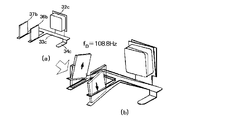
- FIG. 8 is a schematic diagram showing the third embodiment. Specifically, FIG. 8A is a schematic perspective view, FIG. 8B is a schematic top view, and FIG. 8C is a schematic side view.
- FIG. 8 illustration of a polarization beam splitter, a light modulation unit (incident side polarizing plate, liquid crystal panel, output side polarizing plate), dichroic prism, and the like is omitted.
- the optical integrator is divided into a first light tunnel 38 and a second light tunnel 39.
- the projection image display device 29c includes two diffusion plates (a first diffusion plate 36b and a second diffusion plate 37b).
- the first diffusion plate 36b, the first light tunnel 38, the second diffusion plate 37b, and the second light tunnel 39 are arranged on the optical axis in this order.
- the first diffusion plate 36b and the second diffusion plate 37b are connected to an air cooling fan 32c for cooling the semiconductor laser 30c by a plate spring 33c so that the diffusion plates 36b and 37b can individually vibrate.
- the beam diameter of the laser light incident on the light modulator (not shown) is expanded twice, and the luminance distribution is made uniform twice. Therefore, the luminance unevenness is extremely small, and a light beam having an ideal cross-sectional shape can be obtained.
- the plate spring 33c is designed to have a resonance mode in which the first diffusion plate 36b and the second diffusion plate 37b vibrate in opposite phases at the solid propagation frequency of the air cooling fan 32c. Therefore, as in the second embodiment, the relative speed and relative displacement between the first diffusion plate 36b and the second diffusion plate 37b are doubled, and a sufficient speckle pattern integration effect is obtained.
- the vibration mode of the diffusion plate in the second embodiment and the third embodiment will be described based on the result of eigenvalue analysis by simulation.
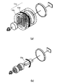
- FIG. 9A is a perspective view of an analysis model of the diffusion plates 36a and 37a in the second embodiment.
- FIG. 9B shows mode shapes of the diffusion plates 36a and 37a at the solid-state propagation frequency of the air cooling fan 32b.
- the analysis model shown in FIG. 9 (a) is modeled by taking out only the drive parts of the diffusion plates 36a and 37a in the second embodiment.
- the first diffusion plate 36a and the second diffusion plate 37a are connected to the air cooling fan 32b via a leaf spring 33b.
- the calculation is performed on the assumption that the fixing portion 34b of the leaf spring 33b is completely fixed.
- the mass of the first diffusion plate 36a and the second diffusion plate 37a is 1 g each, and the plate spring 33b is made of stainless steel having a thickness of 0.5 mm.
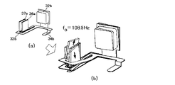
- FIG. 10A is a perspective view of an analysis model of the diffusion plates 36b and 37b in the third embodiment.
- FIG. 10B shows mode shapes of the diffusion plates 36b and 37b at the solid-state propagation frequency of the air cooling fan 32c.
- the analysis model shown in FIG. 10 (a) is modeled by taking out only the drive parts of the diffusion plates 36b and 37b in the third embodiment.
- the first diffusion plate 36b and the second diffusion plate 37b are connected to the air cooling fan 32c via a leaf spring 33c.
- the calculation is performed on the assumption that the fixing portion 34c of the leaf spring 33c is completely fixed.
- the mass of the first diffusion plate 36b and the second diffusion plate 37b is 1 g each, and the leaf spring 33c is made of stainless steel having a thickness of 0.5 mm.
- the first diffusion plate 36b and the second diffusion plate 37b are out of phase with each other at 108.8 kHz which coincides with the solid propagation frequency of the air cooling fan 32c.
- a vibration mode that vibrates in the vertical direction (direction perpendicular to the optical axis) is obtained.
- the speckle pattern of the laser light passing through the two diffusion plates is effectively averaged, and the speckle noise is greatly reduced.
- the shape of the leaf spring shown in the figure is only an example.
- the shape of the leaf spring is not limited to a specific shape as long as a desired vibration mode can be obtained at a predetermined frequency (solid propagation frequency of the fan).
- FIG. 11 is a block diagram of a water cooling system used in this embodiment.
- the 11 includes a heat receiving jacket 41a, a radiator 42a, a circulation pump 43a, and a reserve tank 44a.
- the heat receiving jacket 41a is thermally connected to the heating element 45 and absorbs heat generated by the heating element 45.
- the heat absorbed by the heat receiving jacket 41a is carried to the radiator 42a via the refrigerant liquid flowing in the heat receiving jacket 41a.
- the radiator 42a the refrigerant liquid is cooled by heat exchange (heat radiation) between the refrigerant liquid and the outside air. Natural air cooling or forced air cooling is used for cooling the refrigerant liquid in the radiator 42a.
- the cooled refrigerant liquid is transported by the circulation pump 43a to the heat receiving jacket 41a through the reserve tank 44a.
- the reserve tank 44a compensates for a decrease in the refrigerant liquid due to volatilization, and maintains the amount of the refrigerant liquid in the system.
- the above water cooling system has quiet operation noise and higher cooling performance than the air cooling system, so it is suitable for silent cooling of a heating element with a large amount of heat generation. Therefore, when a high-power semiconductor laser is used in a high-brightness type projector, the above-described water cooling system may be employed as a cooling means for the semiconductor laser.
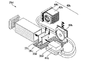
- FIG. 12 is a schematic perspective view of the projection type image display apparatus of the fourth embodiment. Also in FIG. 12, illustration of a polarization beam splitter, a light modulation part (incident side polarizing plate, liquid crystal panel, outgoing side polarizing plate), a dichroic prism, etc. is omitted.
- the first diffusion plate 36c and the second diffusion plate 37c are connected to the circulation pump 43b of the water cooling system 40b via a leaf spring 33d.
- the leaf spring 33d is designed such that the first diffusion plate 36c and the second diffusion plate 37c vibrate in opposite phases at the solid propagation frequency of the circulation pump 43b. Therefore, even when the water cooling system 40b is applied to the cooling of the semiconductor laser 30d, the same effect as that of the second embodiment described above can be obtained.
- the circulation pump 43b in Fig. 12 corresponds to the circulation pump 43a in Fig. 11.
- the heat receiving jacket 41b corresponds to the heat receiving jacket 41a.
- the radiator 42b corresponds to the radiator 42a.
- the reserve tank 44b corresponds to the reserve tank 44a.
- the semiconductor laser 30b corresponds to the heating element 45.
- FIG. 12 shows an example in which the air cooling system of the second embodiment is replaced with a water cooling system.
- the air cooling system of the first embodiment or the third embodiment can be replaced with a water cooling system. .
- a low-power semiconductor laser may be used as a light source.
- a cooling means air cooling fan dedicated to the semiconductor laser may not be prepared.
- the speckle pattern is considerably reduced as compared with the first speckle image.
- the speckle contrast was reduced by 58% or more.
Landscapes
- Physics & Mathematics (AREA)
- Engineering & Computer Science (AREA)
- Multimedia (AREA)
- Signal Processing (AREA)
- General Physics & Mathematics (AREA)
- Optics & Photonics (AREA)
- Projection Apparatus (AREA)
- Liquid Crystal (AREA)
Abstract
Priority Applications (6)
| Application Number | Priority Date | Filing Date | Title |
|---|---|---|---|
| US12/736,284 US8550633B2 (en) | 2008-03-28 | 2008-03-28 | Laser projector having a diffuser vibrated by using component of a cooling mechanism |
| PCT/JP2008/056147 WO2009118902A1 (fr) | 2008-03-28 | 2008-03-28 | Unité d'affichage d'image par projection |
| EP08739265.0A EP2273308A4 (fr) | 2008-03-28 | 2008-03-28 | Unité d'affichage d'image par projection |
| CN2008801283710A CN101981493B (zh) | 2008-03-28 | 2008-03-28 | 投影式图像显示设备 |
| JP2008538219A JP4235769B1 (ja) | 2008-03-28 | 2008-03-28 | 投写型画像表示装置 |
| US14/044,375 US8905549B2 (en) | 2008-03-28 | 2013-10-02 | Laser projector having a diffuser vibrated by using component of a cooling mechanism |
Applications Claiming Priority (1)
| Application Number | Priority Date | Filing Date | Title |
|---|---|---|---|
| PCT/JP2008/056147 WO2009118902A1 (fr) | 2008-03-28 | 2008-03-28 | Unité d'affichage d'image par projection |
Related Child Applications (2)
| Application Number | Title | Priority Date | Filing Date |
|---|---|---|---|
| US12/736,284 A-371-Of-International US8550633B2 (en) | 2008-03-28 | 2008-03-28 | Laser projector having a diffuser vibrated by using component of a cooling mechanism |
| US14/044,375 Continuation US8905549B2 (en) | 2008-03-28 | 2013-10-02 | Laser projector having a diffuser vibrated by using component of a cooling mechanism |
Publications (1)
| Publication Number | Publication Date |
|---|---|
| WO2009118902A1 true WO2009118902A1 (fr) | 2009-10-01 |
Family
ID=40506397
Family Applications (1)
| Application Number | Title | Priority Date | Filing Date |
|---|---|---|---|
| PCT/JP2008/056147 Ceased WO2009118902A1 (fr) | 2008-03-28 | 2008-03-28 | Unité d'affichage d'image par projection |
Country Status (5)
| Country | Link |
|---|---|
| US (2) | US8550633B2 (fr) |
| EP (1) | EP2273308A4 (fr) |
| JP (1) | JP4235769B1 (fr) |
| CN (1) | CN101981493B (fr) |
| WO (1) | WO2009118902A1 (fr) |
Cited By (11)
| Publication number | Priority date | Publication date | Assignee | Title |
|---|---|---|---|---|
| WO2010151296A1 (fr) * | 2009-06-22 | 2010-12-29 | Eastman Kodak Company | Système optique de projection laser équipé d'un élément mobile de réduction de chatoiement et élément d'intégration de lumière |
| JP2012145804A (ja) * | 2011-01-13 | 2012-08-02 | Seiko Epson Corp | プロジェクター |
| WO2012143990A1 (fr) * | 2011-04-18 | 2012-10-26 | Necディスプレイソリューションズ株式会社 | Dispositif d'affichage d'image par projection |
| JP2012226292A (ja) * | 2011-04-04 | 2012-11-15 | Sony Corp | 照明装置および表示装置 |
| WO2013008323A1 (fr) * | 2011-07-13 | 2013-01-17 | Necディスプレイソリューションズ株式会社 | Dispositif de source lumineuse et dispositif d'affichage du type par projection |
| JP2013037335A (ja) * | 2011-07-13 | 2013-02-21 | Sony Corp | 照明装置および表示装置 |
| WO2013140591A1 (fr) * | 2012-03-23 | 2013-09-26 | Necディスプレイソリューションズ株式会社 | Mécanisme de rotation de plaque de diffusion, projecteur, et système projecteur |
| JP2013210487A (ja) * | 2012-03-30 | 2013-10-10 | Dainippon Printing Co Ltd | 照明装置、投射装置および投射型映像表示装置 |
| JP2014153697A (ja) * | 2013-02-14 | 2014-08-25 | Seiko Epson Corp | 照明装置およびプロジェクター |
| JP2015090497A (ja) * | 2013-11-04 | 2015-05-11 | クリスティ デジタル システムズ カナダ インコーポレイテッド | 高ダイナミックレンジのための2段階光変調 |
| JP2017134992A (ja) * | 2016-01-27 | 2017-08-03 | 株式会社リコー | 照明装置、パターン照射装置およびシステム |
Families Citing this family (30)
| Publication number | Priority date | Publication date | Assignee | Title |
|---|---|---|---|---|
| JP4235769B1 (ja) * | 2008-03-28 | 2009-03-11 | Necディスプレイソリューションズ株式会社 | 投写型画像表示装置 |
| JP2010256572A (ja) * | 2009-04-23 | 2010-11-11 | Olympus Corp | 投射型表示装置 |
| US8172404B2 (en) * | 2009-05-21 | 2012-05-08 | Eastman Kodak Company | Projection with lenslet arrangement on speckle reduction element |
| WO2011040479A1 (fr) * | 2009-09-29 | 2011-04-07 | 三洋電機株式会社 | Unité optique, dispositif d'affichage d'image de projection, et élément optique de diffusion |
| US9039192B2 (en) | 2009-11-24 | 2015-05-26 | Nec Display Solutions, Ltd. | Projection display device comprising a light source |
| JP5540991B2 (ja) * | 2010-08-19 | 2014-07-02 | ソニー株式会社 | 光学装置および表示装置 |
| TW201232153A (en) * | 2011-01-26 | 2012-08-01 | Hon Hai Prec Ind Co Ltd | Laser projecting device |
| CN103597400B (zh) * | 2011-04-12 | 2017-05-03 | 巴库股份有限公司 | 散斑减少的激光投影仪 |
| JP2012230321A (ja) * | 2011-04-27 | 2012-11-22 | Hitachi Media Electoronics Co Ltd | 走査型画像表示装置 |
| US8955988B1 (en) | 2011-04-28 | 2015-02-17 | Rawles Llc | Image modification in optical path |
| US9158063B2 (en) * | 2011-07-07 | 2015-10-13 | Reald Inc. | Apparatus for despeckling laser systems and methods thereof |
| CN102591120B (zh) * | 2012-02-22 | 2014-10-15 | 海信集团有限公司 | 光源装置、光源产生方法及包含光源装置的激光投影机 |
| JP5867721B2 (ja) * | 2012-04-02 | 2016-02-24 | ソニー株式会社 | 照明装置および表示装置 |
| TWI504938B (zh) * | 2013-11-21 | 2015-10-21 | Univ Nat Chiao Tung | 照明系統以及投影裝置 |
| US9461286B2 (en) | 2014-08-25 | 2016-10-04 | Ford Global Technologies, Llc | Twist-lock battery pack attachment device |
| US9684181B2 (en) * | 2014-09-19 | 2017-06-20 | Panasonic Intellectual Property Management Co., Ltd. | Optical device and projection video display device |
| WO2016076947A1 (fr) * | 2014-11-12 | 2016-05-19 | Carrier Corporation | Système de réfrigération |
| CN104833367A (zh) * | 2015-05-11 | 2015-08-12 | 京东方科技集团股份有限公司 | 车载投影系统 |
| DE102016111600B4 (de) * | 2015-06-26 | 2021-12-30 | Cognex Corporation | Beleuchtungsanordnung |
| US20170092324A1 (en) * | 2015-09-30 | 2017-03-30 | Apple Inc. | Automatic Video Compositing |
| CN106918865A (zh) * | 2015-12-28 | 2017-07-04 | 无锡视美乐激光显示科技有限公司 | 导光装置及其应用的投影设备 |
| TWI592609B (zh) | 2015-12-30 | 2017-07-21 | 中強光電股份有限公司 | 照明系統以及投影裝置 |
| JP6641028B2 (ja) * | 2016-11-18 | 2020-02-05 | Necディスプレイソリューションズ株式会社 | 輝度調整装置、表示装置及び輝度調整方法 |
| JP6851029B2 (ja) * | 2017-03-09 | 2021-03-31 | パナソニックIpマネジメント株式会社 | 投射光源装置 |
| CN107787164B (zh) * | 2017-09-26 | 2019-08-27 | 青岛海信电器股份有限公司 | 一种液冷块、液冷散热系统以及激光投影机 |
| JP6992502B2 (ja) * | 2017-12-27 | 2022-01-13 | セイコーエプソン株式会社 | プロジェクター |
| CN112859497B (zh) * | 2019-11-12 | 2023-07-14 | 深圳光峰科技股份有限公司 | 激光投影显示系统 |
| US20210165236A1 (en) * | 2019-12-03 | 2021-06-03 | Corning Incorporated | Acoustically coupled vibration of an optical component for reducing laser coherence effects including speckle |
| JP7485567B2 (ja) | 2020-08-14 | 2024-05-16 | デクセリアルズ株式会社 | 光学系、表示装置、投影装置及び照明装置 |
| CN120522956A (zh) * | 2024-02-21 | 2025-08-22 | 台达电子工业股份有限公司 | 激光投影机 |
Citations (5)
| Publication number | Priority date | Publication date | Assignee | Title |
|---|---|---|---|---|
| JPH07297111A (ja) | 1994-04-27 | 1995-11-10 | Sony Corp | 露光照明装置 |
| JPH1164789A (ja) | 1997-08-15 | 1999-03-05 | Sony Corp | レーザディスプレイ装置 |
| JP2003098476A (ja) | 2001-08-27 | 2003-04-03 | Eastman Kodak Co | レーザ投影型表示システム |
| WO2005008330A1 (fr) | 2003-07-22 | 2005-01-27 | Matsushita Electric Industrial Co., Ltd. | Appareil de formation d'image bidimensionnel |
| WO2006095855A1 (fr) * | 2005-03-11 | 2006-09-14 | Matsushita Electric Industrial Co., Ltd. | Projecteur d’images |
Family Cites Families (11)
| Publication number | Priority date | Publication date | Assignee | Title |
|---|---|---|---|---|
| JP2003149567A (ja) * | 2001-11-16 | 2003-05-21 | Toshiba Corp | レーザ光源装置 |
| CN100531534C (zh) * | 2003-05-30 | 2009-08-19 | 松下电器产业株式会社 | 冷却装置 |
| US7156522B2 (en) * | 2003-07-16 | 2007-01-02 | Plut William J | Projection-type display devices with reduced weight and size |
| JP4307206B2 (ja) * | 2003-09-30 | 2009-08-05 | パナソニック株式会社 | ディスプレイ装置 |
| US7399084B2 (en) * | 2004-04-09 | 2008-07-15 | Matsushita Electric Industrial Co., Ltd. | Laser image display apparatus |
| JP4581946B2 (ja) * | 2005-09-29 | 2010-11-17 | セイコーエプソン株式会社 | 画像表示装置 |
| JP2007279204A (ja) * | 2006-04-04 | 2007-10-25 | Seiko Epson Corp | プロジェクタ |
| US20080088804A1 (en) * | 2006-10-13 | 2008-04-17 | Mark Peterson | Method, System and Apparatus for Diffuser Vibration |
| WO2009104392A1 (fr) * | 2008-02-20 | 2009-08-27 | パナソニック株式会社 | Dispositif de source de lumière, dispositif d'éclairage et dispositif d'affichage d'image |
| US20090213350A1 (en) * | 2008-02-22 | 2009-08-27 | Nikon Corporation | Coherence-reduction devices and methods for pulsed lasers |
| JP4235769B1 (ja) * | 2008-03-28 | 2009-03-11 | Necディスプレイソリューションズ株式会社 | 投写型画像表示装置 |
-
2008
- 2008-03-28 JP JP2008538219A patent/JP4235769B1/ja not_active Expired - Fee Related
- 2008-03-28 WO PCT/JP2008/056147 patent/WO2009118902A1/fr not_active Ceased
- 2008-03-28 EP EP08739265.0A patent/EP2273308A4/fr not_active Withdrawn
- 2008-03-28 CN CN2008801283710A patent/CN101981493B/zh not_active Expired - Fee Related
- 2008-03-28 US US12/736,284 patent/US8550633B2/en not_active Expired - Fee Related
-
2013
- 2013-10-02 US US14/044,375 patent/US8905549B2/en not_active Expired - Fee Related
Patent Citations (5)
| Publication number | Priority date | Publication date | Assignee | Title |
|---|---|---|---|---|
| JPH07297111A (ja) | 1994-04-27 | 1995-11-10 | Sony Corp | 露光照明装置 |
| JPH1164789A (ja) | 1997-08-15 | 1999-03-05 | Sony Corp | レーザディスプレイ装置 |
| JP2003098476A (ja) | 2001-08-27 | 2003-04-03 | Eastman Kodak Co | レーザ投影型表示システム |
| WO2005008330A1 (fr) | 2003-07-22 | 2005-01-27 | Matsushita Electric Industrial Co., Ltd. | Appareil de formation d'image bidimensionnel |
| WO2006095855A1 (fr) * | 2005-03-11 | 2006-09-14 | Matsushita Electric Industrial Co., Ltd. | Projecteur d’images |
Non-Patent Citations (1)
| Title |
|---|
| See also references of EP2273308A4 |
Cited By (14)
| Publication number | Priority date | Publication date | Assignee | Title |
|---|---|---|---|---|
| WO2010151296A1 (fr) * | 2009-06-22 | 2010-12-29 | Eastman Kodak Company | Système optique de projection laser équipé d'un élément mobile de réduction de chatoiement et élément d'intégration de lumière |
| US8235531B2 (en) | 2009-06-22 | 2012-08-07 | Eastman Kodak Company | Optical interference reducing element for laser projection |
| JP2012145804A (ja) * | 2011-01-13 | 2012-08-02 | Seiko Epson Corp | プロジェクター |
| JP2012226292A (ja) * | 2011-04-04 | 2012-11-15 | Sony Corp | 照明装置および表示装置 |
| WO2012143990A1 (fr) * | 2011-04-18 | 2012-10-26 | Necディスプレイソリューションズ株式会社 | Dispositif d'affichage d'image par projection |
| US9500935B2 (en) | 2011-04-18 | 2016-11-22 | Nec Display Solutions, Ltd. | Projection image display device |
| JP2013037335A (ja) * | 2011-07-13 | 2013-02-21 | Sony Corp | 照明装置および表示装置 |
| US9448416B2 (en) | 2011-07-13 | 2016-09-20 | Nec Display Solutions, Ltd. | Light source device and projection-type display device |
| WO2013008323A1 (fr) * | 2011-07-13 | 2013-01-17 | Necディスプレイソリューションズ株式会社 | Dispositif de source lumineuse et dispositif d'affichage du type par projection |
| WO2013140591A1 (fr) * | 2012-03-23 | 2013-09-26 | Necディスプレイソリューションズ株式会社 | Mécanisme de rotation de plaque de diffusion, projecteur, et système projecteur |
| JP2013210487A (ja) * | 2012-03-30 | 2013-10-10 | Dainippon Printing Co Ltd | 照明装置、投射装置および投射型映像表示装置 |
| JP2014153697A (ja) * | 2013-02-14 | 2014-08-25 | Seiko Epson Corp | 照明装置およびプロジェクター |
| JP2015090497A (ja) * | 2013-11-04 | 2015-05-11 | クリスティ デジタル システムズ カナダ インコーポレイテッド | 高ダイナミックレンジのための2段階光変調 |
| JP2017134992A (ja) * | 2016-01-27 | 2017-08-03 | 株式会社リコー | 照明装置、パターン照射装置およびシステム |
Also Published As
| Publication number | Publication date |
|---|---|
| CN101981493B (zh) | 2012-12-19 |
| EP2273308A1 (fr) | 2011-01-12 |
| EP2273308A4 (fr) | 2014-04-02 |
| CN101981493A (zh) | 2011-02-23 |
| US8905549B2 (en) | 2014-12-09 |
| US20140036238A1 (en) | 2014-02-06 |
| JP4235769B1 (ja) | 2009-03-11 |
| US20110013149A1 (en) | 2011-01-20 |
| US8550633B2 (en) | 2013-10-08 |
| JPWO2009118902A1 (ja) | 2011-07-21 |
Similar Documents
| Publication | Publication Date | Title |
|---|---|---|
| JP4235769B1 (ja) | 投写型画像表示装置 | |
| US9448416B2 (en) | Light source device and projection-type display device | |
| US9500935B2 (en) | Projection image display device | |
| US7370973B2 (en) | Displaying optical system and image projection apparatus | |
| TWI485439B (zh) | 用於減少經投影影像中之斑點之裝置及方法 | |
| JP4898121B2 (ja) | 画像投影装置 | |
| US9176367B2 (en) | Illumination device and display unit including a light source section, first and second uniformization optical members, an optical device, and a drive section | |
| CN101681078B (zh) | 光源装置、照明装置以及图像显示装置 | |
| JP2012088451A (ja) | 照明装置および表示装置 | |
| KR20100106487A (ko) | 광학계 및 방법 | |
| CN102734700B (zh) | 照明装置和显示单元 | |
| JP2004534276A (ja) | 画像投影装置および方法 | |
| WO2007116935A1 (fr) | Affichage par projection et element de reduction de la granularite | |
| JP2003098476A (ja) | レーザ投影型表示システム | |
| JP2013044800A (ja) | 照明装置および表示装置 | |
| JP2004144936A (ja) | 照明装置及び画像表示装置 | |
| JP2004138669A (ja) | 照明装置及び画像表示装置 | |
| JP2009527772A (ja) | レーザ投影ディスプレイのための角度走査によるスペックル低減装置及び方法 | |
| US10976565B2 (en) | Speckle reduction device and method of reducing speckle | |
| JP2009003091A (ja) | 照明光学装置及び投写型画像表示装置 | |
| JP2014178693A (ja) | 照明装置および表示装置 | |
| Niesten et al. | Scanning laser beam displays | |
| JP2008122823A (ja) | プロジェクタ | |
| KR20190094309A (ko) | 전자 디바이스 | |
| JP2007241024A (ja) | シンチレーション除去装置及びプロジェクタ |
Legal Events
| Date | Code | Title | Description |
|---|---|---|---|
| WWE | Wipo information: entry into national phase |
Ref document number: 200880128371.0 Country of ref document: CN |
|
| WWE | Wipo information: entry into national phase |
Ref document number: 2008538219 Country of ref document: JP |
|
| 121 | Ep: the epo has been informed by wipo that ep was designated in this application |
Ref document number: 08739265 Country of ref document: EP Kind code of ref document: A1 |
|
| REEP | Request for entry into the european phase |
Ref document number: 2008739265 Country of ref document: EP |
|
| WWE | Wipo information: entry into national phase |
Ref document number: 2008739265 Country of ref document: EP |
|
| WWE | Wipo information: entry into national phase |
Ref document number: 12736284 Country of ref document: US |
|
| NENP | Non-entry into the national phase |
Ref country code: DE |