WO2009128381A1 - Feuille de nettoyage et son procédé de production - Google Patents
Feuille de nettoyage et son procédé de production Download PDFInfo
- Publication number
- WO2009128381A1 WO2009128381A1 PCT/JP2009/057248 JP2009057248W WO2009128381A1 WO 2009128381 A1 WO2009128381 A1 WO 2009128381A1 JP 2009057248 W JP2009057248 W JP 2009057248W WO 2009128381 A1 WO2009128381 A1 WO 2009128381A1
- Authority
- WO
- WIPO (PCT)
- Prior art keywords
- sheet
- fiber
- long
- cleaning
- long fibers
- Prior art date
- Legal status (The legal status is an assumption and is not a legal conclusion. Google has not performed a legal analysis and makes no representation as to the accuracy of the status listed.)
- Ceased
Links
Images


Classifications
-
- A—HUMAN NECESSITIES
- A47—FURNITURE; DOMESTIC ARTICLES OR APPLIANCES; COFFEE MILLS; SPICE MILLS; SUCTION CLEANERS IN GENERAL
- A47L—DOMESTIC WASHING OR CLEANING; SUCTION CLEANERS IN GENERAL
- A47L13/00—Implements for cleaning floors, carpets, furniture, walls, or wall coverings
- A47L13/10—Scrubbing; Scouring; Cleaning; Polishing
- A47L13/20—Mops
-
- A—HUMAN NECESSITIES
- A47—FURNITURE; DOMESTIC ARTICLES OR APPLIANCES; COFFEE MILLS; SPICE MILLS; SUCTION CLEANERS IN GENERAL
- A47L—DOMESTIC WASHING OR CLEANING; SUCTION CLEANERS IN GENERAL
- A47L13/00—Implements for cleaning floors, carpets, furniture, walls, or wall coverings
- A47L13/10—Scrubbing; Scouring; Cleaning; Polishing
- A47L13/38—Other dusting implements
-
- B—PERFORMING OPERATIONS; TRANSPORTING
- B32—LAYERED PRODUCTS
- B32B—LAYERED PRODUCTS, i.e. PRODUCTS BUILT-UP OF STRATA OF FLAT OR NON-FLAT, e.g. CELLULAR OR HONEYCOMB, FORM
- B32B5/00—Layered products characterised by the non- homogeneity or physical structure, i.e. comprising a fibrous, filamentary, particulate or foam layer; Layered products characterised by having a layer differing constitutionally or physically in different parts
- B32B5/02—Layered products characterised by the non- homogeneity or physical structure, i.e. comprising a fibrous, filamentary, particulate or foam layer; Layered products characterised by having a layer differing constitutionally or physically in different parts characterised by structural features of a fibrous or filamentary layer
- B32B5/08—Layered products characterised by the non- homogeneity or physical structure, i.e. comprising a fibrous, filamentary, particulate or foam layer; Layered products characterised by having a layer differing constitutionally or physically in different parts characterised by structural features of a fibrous or filamentary layer the fibres or filaments of a layer being of different substances, e.g. conjugate fibres, mixture of different fibres
-
- B—PERFORMING OPERATIONS; TRANSPORTING
- B32—LAYERED PRODUCTS
- B32B—LAYERED PRODUCTS, i.e. PRODUCTS BUILT-UP OF STRATA OF FLAT OR NON-FLAT, e.g. CELLULAR OR HONEYCOMB, FORM
- B32B5/00—Layered products characterised by the non- homogeneity or physical structure, i.e. comprising a fibrous, filamentary, particulate or foam layer; Layered products characterised by having a layer differing constitutionally or physically in different parts
- B32B5/22—Layered products characterised by the non- homogeneity or physical structure, i.e. comprising a fibrous, filamentary, particulate or foam layer; Layered products characterised by having a layer differing constitutionally or physically in different parts characterised by the presence of two or more layers which are next to each other and are fibrous, filamentary, formed of particles or foamed
- B32B5/24—Layered products characterised by the non- homogeneity or physical structure, i.e. comprising a fibrous, filamentary, particulate or foam layer; Layered products characterised by having a layer differing constitutionally or physically in different parts characterised by the presence of two or more layers which are next to each other and are fibrous, filamentary, formed of particles or foamed one layer being a fibrous or filamentary layer
- B32B5/26—Layered products characterised by the non- homogeneity or physical structure, i.e. comprising a fibrous, filamentary, particulate or foam layer; Layered products characterised by having a layer differing constitutionally or physically in different parts characterised by the presence of two or more layers which are next to each other and are fibrous, filamentary, formed of particles or foamed one layer being a fibrous or filamentary layer another layer next to it also being fibrous or filamentary
-
- D—TEXTILES; PAPER
- D04—BRAIDING; LACE-MAKING; KNITTING; TRIMMINGS; NON-WOVEN FABRICS
- D04H—MAKING TEXTILE FABRICS, e.g. FROM FIBRES OR FILAMENTARY MATERIAL; FABRICS MADE BY SUCH PROCESSES OR APPARATUS, e.g. FELTS, NON-WOVEN FABRICS; COTTON-WOOL; WADDING ; NON-WOVEN FABRICS FROM STAPLE FIBRES, FILAMENTS OR YARNS, BONDED WITH AT LEAST ONE WEB-LIKE MATERIAL DURING THEIR CONSOLIDATION
- D04H11/00—Non-woven pile fabrics
-
- D—TEXTILES; PAPER
- D04—BRAIDING; LACE-MAKING; KNITTING; TRIMMINGS; NON-WOVEN FABRICS
- D04H—MAKING TEXTILE FABRICS, e.g. FROM FIBRES OR FILAMENTARY MATERIAL; FABRICS MADE BY SUCH PROCESSES OR APPARATUS, e.g. FELTS, NON-WOVEN FABRICS; COTTON-WOOL; WADDING ; NON-WOVEN FABRICS FROM STAPLE FIBRES, FILAMENTS OR YARNS, BONDED WITH AT LEAST ONE WEB-LIKE MATERIAL DURING THEIR CONSOLIDATION
- D04H3/00—Non-woven fabrics formed wholly or mainly of yarns or like filamentary material of substantial length
- D04H3/02—Non-woven fabrics formed wholly or mainly of yarns or like filamentary material of substantial length characterised by the method of forming fleeces or layers, e.g. reorientation of yarns or filaments
- D04H3/04—Non-woven fabrics formed wholly or mainly of yarns or like filamentary material of substantial length characterised by the method of forming fleeces or layers, e.g. reorientation of yarns or filaments in rectilinear paths, e.g. crossing at right angles
-
- D—TEXTILES; PAPER
- D04—BRAIDING; LACE-MAKING; KNITTING; TRIMMINGS; NON-WOVEN FABRICS
- D04H—MAKING TEXTILE FABRICS, e.g. FROM FIBRES OR FILAMENTARY MATERIAL; FABRICS MADE BY SUCH PROCESSES OR APPARATUS, e.g. FELTS, NON-WOVEN FABRICS; COTTON-WOOL; WADDING ; NON-WOVEN FABRICS FROM STAPLE FIBRES, FILAMENTS OR YARNS, BONDED WITH AT LEAST ONE WEB-LIKE MATERIAL DURING THEIR CONSOLIDATION
- D04H3/00—Non-woven fabrics formed wholly or mainly of yarns or like filamentary material of substantial length
- D04H3/08—Non-woven fabrics formed wholly or mainly of yarns or like filamentary material of substantial length characterised by the method of strengthening or consolidating
- D04H3/14—Non-woven fabrics formed wholly or mainly of yarns or like filamentary material of substantial length characterised by the method of strengthening or consolidating with bonds between thermoplastic yarns or filaments produced by welding
-
- A—HUMAN NECESSITIES
- A47—FURNITURE; DOMESTIC ARTICLES OR APPLIANCES; COFFEE MILLS; SPICE MILLS; SUCTION CLEANERS IN GENERAL
- A47L—DOMESTIC WASHING OR CLEANING; SUCTION CLEANERS IN GENERAL
- A47L13/00—Implements for cleaning floors, carpets, furniture, walls, or wall coverings
- A47L13/10—Scrubbing; Scouring; Cleaning; Polishing
- A47L13/40—Cleaning implements actuated by electrostatic attraction; Devices for cleaning same; Magnetic cleaning implements
-
- B—PERFORMING OPERATIONS; TRANSPORTING
- B29—WORKING OF PLASTICS; WORKING OF SUBSTANCES IN A PLASTIC STATE IN GENERAL
- B29C—SHAPING OR JOINING OF PLASTICS; SHAPING OF MATERIAL IN A PLASTIC STATE, NOT OTHERWISE PROVIDED FOR; AFTER-TREATMENT OF THE SHAPED PRODUCTS, e.g. REPAIRING
- B29C2793/00—Shaping techniques involving a cutting or machining operation
- B29C2793/009—Shaping techniques involving a cutting or machining operation after shaping
-
- B—PERFORMING OPERATIONS; TRANSPORTING
- B29—WORKING OF PLASTICS; WORKING OF SUBSTANCES IN A PLASTIC STATE IN GENERAL
- B29C—SHAPING OR JOINING OF PLASTICS; SHAPING OF MATERIAL IN A PLASTIC STATE, NOT OTHERWISE PROVIDED FOR; AFTER-TREATMENT OF THE SHAPED PRODUCTS, e.g. REPAIRING
- B29C65/00—Joining or sealing of preformed parts, e.g. welding of plastics materials; Apparatus therefor
- B29C65/02—Joining or sealing of preformed parts, e.g. welding of plastics materials; Apparatus therefor by heating, with or without pressure
- B29C65/08—Joining or sealing of preformed parts, e.g. welding of plastics materials; Apparatus therefor by heating, with or without pressure using ultrasonic vibrations
- B29C65/083—Joining or sealing of preformed parts, e.g. welding of plastics materials; Apparatus therefor by heating, with or without pressure using ultrasonic vibrations using a rotary sonotrode or a rotary anvil
- B29C65/086—Joining or sealing of preformed parts, e.g. welding of plastics materials; Apparatus therefor by heating, with or without pressure using ultrasonic vibrations using a rotary sonotrode or a rotary anvil using a rotary anvil
-
- B—PERFORMING OPERATIONS; TRANSPORTING
- B29—WORKING OF PLASTICS; WORKING OF SUBSTANCES IN A PLASTIC STATE IN GENERAL
- B29C—SHAPING OR JOINING OF PLASTICS; SHAPING OF MATERIAL IN A PLASTIC STATE, NOT OTHERWISE PROVIDED FOR; AFTER-TREATMENT OF THE SHAPED PRODUCTS, e.g. REPAIRING
- B29C65/00—Joining or sealing of preformed parts, e.g. welding of plastics materials; Apparatus therefor
- B29C65/02—Joining or sealing of preformed parts, e.g. welding of plastics materials; Apparatus therefor by heating, with or without pressure
- B29C65/18—Joining or sealing of preformed parts, e.g. welding of plastics materials; Apparatus therefor by heating, with or without pressure using heated tools
-
- B—PERFORMING OPERATIONS; TRANSPORTING
- B29—WORKING OF PLASTICS; WORKING OF SUBSTANCES IN A PLASTIC STATE IN GENERAL
- B29C—SHAPING OR JOINING OF PLASTICS; SHAPING OF MATERIAL IN A PLASTIC STATE, NOT OTHERWISE PROVIDED FOR; AFTER-TREATMENT OF THE SHAPED PRODUCTS, e.g. REPAIRING
- B29C66/00—General aspects of processes or apparatus for joining preformed parts
- B29C66/01—General aspects dealing with the joint area or with the area to be joined
- B29C66/05—Particular design of joint configurations
- B29C66/20—Particular design of joint configurations particular design of the joint lines, e.g. of the weld lines
- B29C66/21—Particular design of joint configurations particular design of the joint lines, e.g. of the weld lines said joint lines being formed by a single dot or dash or by several dots or dashes, i.e. spot joining or spot welding
-
- B—PERFORMING OPERATIONS; TRANSPORTING
- B29—WORKING OF PLASTICS; WORKING OF SUBSTANCES IN A PLASTIC STATE IN GENERAL
- B29C—SHAPING OR JOINING OF PLASTICS; SHAPING OF MATERIAL IN A PLASTIC STATE, NOT OTHERWISE PROVIDED FOR; AFTER-TREATMENT OF THE SHAPED PRODUCTS, e.g. REPAIRING
- B29C66/00—General aspects of processes or apparatus for joining preformed parts
- B29C66/01—General aspects dealing with the joint area or with the area to be joined
- B29C66/05—Particular design of joint configurations
- B29C66/20—Particular design of joint configurations particular design of the joint lines, e.g. of the weld lines
- B29C66/23—Particular design of joint configurations particular design of the joint lines, e.g. of the weld lines said joint lines being multiple and parallel or being in the form of tessellations
- B29C66/232—Particular design of joint configurations particular design of the joint lines, e.g. of the weld lines said joint lines being multiple and parallel or being in the form of tessellations said joint lines being multiple and parallel, i.e. the joint being formed by several parallel joint lines
-
- B—PERFORMING OPERATIONS; TRANSPORTING
- B29—WORKING OF PLASTICS; WORKING OF SUBSTANCES IN A PLASTIC STATE IN GENERAL
- B29C—SHAPING OR JOINING OF PLASTICS; SHAPING OF MATERIAL IN A PLASTIC STATE, NOT OTHERWISE PROVIDED FOR; AFTER-TREATMENT OF THE SHAPED PRODUCTS, e.g. REPAIRING
- B29C66/00—General aspects of processes or apparatus for joining preformed parts
- B29C66/69—General aspects of joining filaments
-
- B—PERFORMING OPERATIONS; TRANSPORTING
- B29—WORKING OF PLASTICS; WORKING OF SUBSTANCES IN A PLASTIC STATE IN GENERAL
- B29C—SHAPING OR JOINING OF PLASTICS; SHAPING OF MATERIAL IN A PLASTIC STATE, NOT OTHERWISE PROVIDED FOR; AFTER-TREATMENT OF THE SHAPED PRODUCTS, e.g. REPAIRING
- B29C66/00—General aspects of processes or apparatus for joining preformed parts
- B29C66/70—General aspects of processes or apparatus for joining preformed parts characterised by the composition, physical properties or the structure of the material of the parts to be joined; Joining with non-plastics material
- B29C66/71—General aspects of processes or apparatus for joining preformed parts characterised by the composition, physical properties or the structure of the material of the parts to be joined; Joining with non-plastics material characterised by the composition of the plastics material of the parts to be joined
-
- B—PERFORMING OPERATIONS; TRANSPORTING
- B29—WORKING OF PLASTICS; WORKING OF SUBSTANCES IN A PLASTIC STATE IN GENERAL
- B29C—SHAPING OR JOINING OF PLASTICS; SHAPING OF MATERIAL IN A PLASTIC STATE, NOT OTHERWISE PROVIDED FOR; AFTER-TREATMENT OF THE SHAPED PRODUCTS, e.g. REPAIRING
- B29C66/00—General aspects of processes or apparatus for joining preformed parts
- B29C66/70—General aspects of processes or apparatus for joining preformed parts characterised by the composition, physical properties or the structure of the material of the parts to be joined; Joining with non-plastics material
- B29C66/72—General aspects of processes or apparatus for joining preformed parts characterised by the composition, physical properties or the structure of the material of the parts to be joined; Joining with non-plastics material characterised by the structure of the material of the parts to be joined
- B29C66/729—Textile or other fibrous material made from plastics
- B29C66/7294—Non woven mats, e.g. felt
-
- B—PERFORMING OPERATIONS; TRANSPORTING
- B29—WORKING OF PLASTICS; WORKING OF SUBSTANCES IN A PLASTIC STATE IN GENERAL
- B29L—INDEXING SCHEME ASSOCIATED WITH SUBCLASS B29C, RELATING TO PARTICULAR ARTICLES
- B29L2031/00—Other particular articles
- B29L2031/74—Domestic articles
- B29L2031/7406—Sponges; Cleaning equipment
-
- Y—GENERAL TAGGING OF NEW TECHNOLOGICAL DEVELOPMENTS; GENERAL TAGGING OF CROSS-SECTIONAL TECHNOLOGIES SPANNING OVER SEVERAL SECTIONS OF THE IPC; TECHNICAL SUBJECTS COVERED BY FORMER USPC CROSS-REFERENCE ART COLLECTIONS [XRACs] AND DIGESTS
- Y10—TECHNICAL SUBJECTS COVERED BY FORMER USPC
- Y10T—TECHNICAL SUBJECTS COVERED BY FORMER US CLASSIFICATION
- Y10T156/00—Adhesive bonding and miscellaneous chemical manufacture
- Y10T156/10—Methods of surface bonding and/or assembly therefor
- Y10T156/1052—Methods of surface bonding and/or assembly therefor with cutting, punching, tearing or severing
Definitions
- the present invention relates to a cleaning sheet comprising a plurality of long fibers oriented substantially in one direction.
- a cleaning sheet provided with countless long fibers is known as a cleaning sheet that is used by being mounted on a head unit in a cleaning tool having a head unit and a handle connected to the head unit.
- a cleaning sheet that is used by being mounted on a head unit in a cleaning tool having a head unit and a handle connected to the head unit.
- Patent Document 1 an infinite number of heat-fusible long fibers extending in one direction are continuously extended in a direction intersecting with the fibers and intermittently provided in the direction in which the heat-fusible long fibers extend.
- a cleaning sheet formed by being joined to a heat-sealing sheet by the welded portion thus disclosed is disclosed.
- Patent Document 2 in order to improve the degree of freedom of the heat-fusible long fibers, innumerable heat-fusible long fibers are cut between adjacent welded portions, and the length of the heat-fusible long fibers is determined.
- seat for cleaning including the process which bisects is described.
- Patent Document 3 in order to improve the degree of freedom of the heat-fusible long fibers, a number of heat-fusible long fibers are cut between adjacent continuously extending weld parts, and the lengths are different. A cleaning sheet provided with heat-fusible long fibers is described.
- the cleaning sheet described in Patent Document 3 is arranged between the adjacent continuously extending weld portions by arranging intermittent cutting lines in the same direction as the continuously extending weld portions. Since the heat-fusible long fibers are cut, a large number of heat-fusible long fibers between adjacent welded portions are not completely separated. Therefore, the freedom degree of the heat-fusible continuous fiber between the adjacent welding parts extended continuously is restrict
- the degree of freedom of the long-fiber bundle is not limited by the joint portion for joining the heat-fusible long fiber and the heat-fusion sheet, and the degree of freedom of the heat-fusible long fiber is improved and dust collection
- the present invention relates to a cleaning sheet having excellent properties and a method for manufacturing the same.
- the degree of freedom of the heat-fusible long fiber is not limited by the joining portion for joining the heat-fusible long fiber and the heat-fusible sheet, and the heat-fusible long fiber is caught on the object to be cleaned. It relates to a difficult cleaning sheet. Further, the present invention relates to a cleaning sheet having a random length from the welded portion to the tip of the heat-fusible long fiber and having excellent dust collection properties.
- the present invention is a cleaning sheet provided with at least one long fiber bundle in which long fibers oriented substantially in one direction are gathered on at least one surface of a base sheet.
- the long fiber bundle is formed by bonding long fibers to each other by a fiber bonding portion extending linearly in a direction orthogonal to the orientation direction of the long fibers.
- the cleaning sheet is formed by bonding a long fiber bundle to a base sheet through a sheet bonding portion.
- the cleaning sheet is formed such that all of the fiber bonding portions or at least a part of the fiber bonding portions are not bonded to the base sheet, and the sheet bonding portions are in contact with the fiber bonding portions at a right angle.
- the present invention unwinds the aggregate of the long fibers oriented in one direction, widens them to a predetermined width, and joins the long fibers together by the fiber joining portion extending in a direction intersecting the orientation direction of the long fibers.
- the present invention is based on a long fiber bundle in which a large number of long fibers oriented substantially in one direction are made into a fiber bundle by a plurality of fiber joints extending linearly in a direction intersecting the orientation direction of the long fibers. It is the cleaning sheet joined on at least one surface of the material sheet.
- the plurality of fiber joint portions are arranged at a predetermined interval, and a plurality of long fibers are cut at a plurality of linear cut portions between adjacent fiber joint portions.
- two discontinuous lines in which linear cut portions and uncut portions are alternately arranged are formed in parallel between adjacent fiber joint portions. The two discontinuous lines of the cleaning sheet are continuous when viewed from the orientation direction of the long fibers.
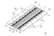
- FIG. 1 is a perspective view of a cleaning sheet according to the first embodiment of the present invention.
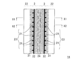
- FIG. 2 is a plan view of the cleaning sheet shown in FIG.
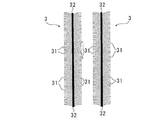
- FIG. 3 is a plan view showing the form of long fiber bundles in the cleaning sheet shown in FIG. 1.
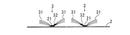
- 4 is a partial cross-sectional view taken along line X1-X1 of the cleaning sheet shown in FIG.
- FIG. 5 is a partial cross-sectional view taken along line X2-X2 of the cleaning sheet shown in FIG.
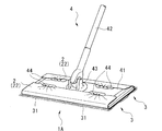
- FIG. 6 is a perspective view showing a state where the cleaning sheet shown in FIG. 1 is mounted on a cleaning tool.
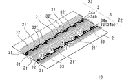
- FIG. 7 is a perspective view of a cleaning sheet according to the second embodiment of the present invention.
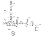
- FIG. 8 is a diagram schematically showing the whole aspect of one embodiment of the method for manufacturing a cleaning sheet of the present invention.
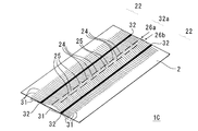
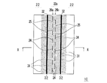
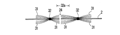
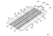
- FIG. 9 is a perspective view of a cleaning sheet according to the third embodiment of the present invention. 10 is a plan view of the cleaning sheet shown in FIG. 11 is a partial cross-sectional view taken along line X1-X1 of the cleaning sheet shown in FIG.
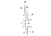
- FIG. 12 is an enlarged view of a plurality of linear cut portions of the cleaning sheet according to the third embodiment.
- FIG. 13 is a perspective view showing a state where the cleaning sheet shown in FIG. 9 is mounted on a cleaning tool.
- FIG. 14 is a perspective view of a cleaning sheet according to the fourth embodiment of the present invention.
- FIG. 15 is a perspective view of a cleaning sheet according to the fifth embodiment of the present invention.
- FIG. 16 is a perspective view of a cleaning sheet according to the sixth embodiment of the present invention.
- FIG. 17 is a partial cross-sectional view taken along line X1-X1 of the cleaning sheet according to another embodiment of the present invention.
- the cleaning sheet 1A of the first embodiment is a long fiber bundle in which long fibers 31 that are oriented substantially in one direction are gathered on at least one surface of the base sheet 2.
- 3 is a cleaning sheet including at least one 3.
- the long fiber bundle 3 is formed by bonding long fibers 31 to each other by a fiber bonding portion 32 extending linearly in a direction intersecting with the orientation direction of the long fibers 31.
- 1 A of cleaning sheets join the long fiber bundle 3 formed in this way to the base material sheet 2 via the sheet
- the plurality of sheet joining portions 21 of the cleaning sheet 1 ⁇ / b> A are intermittently arranged in a direction intersecting with the orientation direction of the long fibers 31.
- the cleaning sheet 1A of the first embodiment will be described in detail.
- the cleaning sheet 1A is provided with preferably 2 to 30 long fiber bundles 3 on one or both sides of the base sheet 2 on one side.
- a cleaning sheet 1A provided with two long fiber bundles 3 on one side on both sides of the base sheet 2 will be specifically described with reference to the drawings.
- the base sheet 2 has a rectangular shape, the length of the base sheet 2 is 10 cm to 60 cm, and the width of the base sheet 2 is 5 cm to 40 cm. .
- the cleaning sheet 1 ⁇ / b> A the long fiber bundle 3 is arranged on both surfaces of the base sheet 2 via the sheet bonding portion 21.
- the long fibers 31 constituting the long fiber bundle 3 are usually oriented in the conveying direction of the material at the time of manufacture.
- “the long fibers 31 are substantially oriented in one direction” means that the orientation direction of some of the long fibers 31 is different due to manufacturing errors, crimp processing of the long fibers 31, etc. This means that the case where it deviates from the orientation direction of most of the long fibers 31 is not excluded.
- the long fiber bundle 3 includes a number 1 of continuous fibers 31 extending continuously in a direction orthogonal to the orientation direction of the long fibers 31, as shown in FIG. 3. It is formed by being joined by the fiber joining portion 32 of the book. As shown in FIG. 3, the long fiber bundle 3 has a rectangular shape when viewed macroscopically.
- the long fiber bundle 3 is formed on the both sides of the base sheet 2 in the longitudinal direction of the long fiber bundle 3 and the base sheet, as shown in FIGS. It arrange
- 1 A of cleaning sheets of 1st Embodiment arrange
- the length of the long fiber bundle 3 is the same as the length of the base sheet 2 and the width of the long fiber bundle 3 is 2 cm to 30 cm.
- the width of the base sheet 2 is wider than the total width of the two long fiber bundles 3, and the region in the width direction outside the long fiber bundle 3 in the base sheet 2 (hereinafter, “ The flap 22 ”) is a portion used when being mounted on the head portion of the cleaning tool (details will be described later).
- the long fibers 31 are preferably provided in a length of 1000 to 50000 on one side per 1 cm of the fiber bonded portion 32 in the long fiber bundle 3 from the viewpoint of dust entanglement. More preferably, it is.
- the fiber length of the long fibers 31 is preferably 5 to 150 mm, more preferably 10 to 120 mm, from the viewpoint of dust entanglement.
- the fiber length of the long fiber 31 is the length from the fiber bonding portion 32 to the tip of the long fiber 31.
- the long fibers 31 having such a fiber length are used in a fiber aggregate (tow) state. It is preferable that the fiber assembly (tow) is sufficiently opened using a known opening device.
- the thickness of the long fiber 31 is not particularly critical, but is preferably 0.1 to 200 dtex, particularly 2 to 30 dtex, from the viewpoint of dust entanglement and prevention of damage to the surface to be cleaned. preferable.
- a crimpable fiber as the long fiber 31 because dust entanglement is further improved.
- those having a color other than white for example, orange or light blue
- the fiber joint portion 32 is for forming the long fiber bundle 3, and in this embodiment, at least a part of the fiber joint portion 32 is not joined to the base sheet 2.
- the fiber joint portion 32 is formed by heat fusion or hot melt adhesive, and in the present embodiment, the fiber joint portion 32 is formed by heat fusion of the long fibers 31.
- the fiber bonding portion 32 is formed in one continuous straight line in the direction orthogonal to the orientation direction of the long fibers 31, that is, in the longitudinal direction of the base sheet 2. Yes.
- the length of the fiber bonding portion 32 is the same as the length of the base sheet 2 as shown in FIGS. 1 to 3, and the width of the fiber bonding portion 32 is 0. 0 as shown in FIGS. 5 to 10 mm.
- the sheet joining portion 21 is for joining the long fiber bundle 3 to the base sheet 2 and is formed by heat fusion or hot melt adhesive.
- the sheet joining portion 21 is based on the long fibers 31. It is formed by heat-sealing to the material sheet 2.
- the plurality of sheet joining portions 21 are aligned in a direction orthogonal to the orientation direction of the long fibers 31, that is, in the longitudinal direction of the base sheet 2.
- they are intermittently arranged with the adjacent sheet bonding portions 21 to form a sheet bonding portion group 23 as a whole.
- the intervals between adjacent sheet joining portions 21 are substantially equal.
- the distance between the sheet bonding portion 21 and the adjacent sheet bonding portion 21 is preferably 10 mm to 45 mm, and preferably 15 mm to 40 mm. Further preferred. It is because the freedom degree of a long fiber bundle will become low that the space
- the fiber bonding portion 32 is bonded to the sheet bonding portion 21 as shown in FIG. 4, and at least a part of the fiber bonding portion 32 is based on the base as shown in FIGS. 4 and 5.
- the material sheet 2 is not joined.
- each of the sheet bonding portions 21 is disposed on the fiber bonding portion 32, and is provided so that the sheet bonding portion 21 and the fiber bonding portion 32 are in contact with each other.
- each of the sheet bonding portions 21 is in contact with the fiber bonding portion 32 at a right angle as shown in FIGS. 1 and 2, and the long fiber bundle 3 is attached to the base sheet 2 as shown in FIG. 4. It is made to join. Further, as shown in FIG.
- the long fiber bundle 3 and the base sheet 2 are not joined between the adjacent sheet joining portions 21 and 21, and the long fiber bundle 3 is separated from the base sheet 2. ing. That is, in the fiber bonding portion 32, only the portion that contacts the sheet bonding portion 21 is bonded to the base sheet 2, and the other portion (the portion that does not contact the sheet bonding portion 21 in the fiber bonding portion 32). Then, it is not joined to the base material sheet 2, and the long fiber bundle 3 is separated from the base material sheet 2.
- the cleaning sheet 1 ⁇ / b> A has two sheet joining portion groups 23, 23.
- the material sheet 2 is formed by cutting a plurality of linear cut portions 24.
- the linear cut portions 24 are arranged in two parallel discontinuous linear shapes in which discontinuous portions are alternately arranged in a longitudinal direction of the base sheet 2, so-called staggered shapes. Has been.
- the material for forming the cleaning sheet 1A of the first embodiment will be described.
- the said base material sheet 2 has a softness
- the base material sheet 2 fiber sheets, such as a nonwoven fabric used for the conventional cleaning sheet, can be used. In particular, an air-through nonwoven fabric or a spunbonded nonwoven fabric is preferable.
- the forming material of the base material sheet 2 may be a nonwoven fabric, a net-like sheet, a film, synthetic paper, or a composite material thereof.
- the long fibers 31 heat-weldable synthetic fibers, composite fibers, and crimped fibers obtained by heat-treating them can be used. Further, the long fibers 31 may be subjected to an oil agent impregnation treatment, an antistatic treatment, a charging treatment, a hydrophilization treatment, or the like as necessary.
- the cleaning sheet 1 ⁇ / b> A of the first embodiment uses the base material sheet 2, and the head unit 41 in the cleaning tool 4 including the head unit 41 and the handle 42 connected to the head unit 41. Used by being attached to.
- the cleaning tool 4 shown in FIG. 6 includes a head portion 41 to which the cleaning sheet 1A of the present embodiment can be mounted, and a rod-shaped handle 42 connected to the head portion 41 via a universal joint 43.
- the mounting surface (bottom surface) of the head portion 41 has a rectangular shape in plan view, and in a normal use mode, the cleaning tool 4 performs cleaning by moving the head portion 41 in the width direction (particularly, reciprocating movement). . That is, the cleaning direction of the cleaning tool 4 is the width direction of the head portion 41.
- cleaning sheets of 1st Embodiment are the same as the longitudinal direction of the base material sheet 2, and the longitudinal direction of the head part 41 of the cleaning tool 4, and the center point of the base material sheet 2 and the center point of the head part 41 Are attached to the mounting surface (bottom surface) of the head portion 41.
- the flaps 22 and 22 in the base material sheet 2 are folded back to the upper surface side of the head portion 41. Further, the flap 22 is pushed into a plurality of flexible sheet holding portions 44 having radial slits in the head portion 41. Thereby, the cleaning sheet 1 ⁇ / b> A can be fixed to the head portion 41 of the cleaning tool 4.
- the cleaning sheet 1A of the present embodiment can be used for, for example, floor cleaning. Therefore, the orientation direction of the long fibers 31 of the long fiber bundle 3 coinciding with the width direction of the base sheet 2 is substantially oriented in the cleaning direction of the cleaning tool 30.
- the cleaning sheet 1 ⁇ / b> A of the first embodiment in the state of being mounted on the head portion 41 of the cleaning tool 4, it is used for cleaning such as sweeping cleaning (floor cleaning) of a flooring room in the same manner as a normal mop cleaning tool. be able to.
- the cleaning sheet 1 ⁇ / b> A according to the first embodiment is configured to join the fiber bonding portion 32 for forming the long fiber bundle 3 and the long fiber bundle 3 to the base sheet 2.
- the sheet joining portion 21 exists separately.
- the cleaning sheet 1 ⁇ / b> A is not bonded between the adjacent sheet bonding portions 21 and 21, and the long fiber bundle 3 and the base sheet 2 are separated from each other.
- the bundle 3 is not restrained by the sheet joining portion 21. That is, since the degree of freedom of the long fibers 31 constituting the long fiber bundle 3 is not limited by the sheet bonding portion 21 between the adjacent sheet bonding portions 21 and 21, dust collection of the cleaning sheet 1A is prevented. Concentration is improved.
- the size of each sheet bonding portion 21 is formed long in the orientation direction of the long fibers 31. Therefore, entanglement between the long fibers 31 can be prevented, and the dust collecting property of the cleaning sheet 1A is improved. Moreover, since the magnitude
- a cleaning sheet according to a second embodiment of the present invention will be described with reference to FIG.
- the points that are not particularly described are the same as those of the cleaning sheet 1A of the first embodiment, and the description of the cleaning sheet 1A of the first embodiment is appropriately applied.
- the plurality of fiber joint portions 32 ′ of the cleaning sheet 1 ⁇ / b> B of the second embodiment are in a direction orthogonal to the orientation direction of the long fibers 31, that is, in the longitudinal direction of the base sheet 2.
- the discontinuous portions 33 are formed in two discontinuous linear shapes (so-called zigzag) that are alternately arranged and form a fiber joint portion group as a whole.
- the two fiber junction part groups 34a and 34b are provided.
- the plurality of fiber joint portions 32 ′ of the cleaning sheet 1 ⁇ / b> B of the second embodiment form another fiber joint portion group 34 a and 34 b when viewed from the width direction of the base sheet 2.
- the ends of adjacent fiber joint portions 32 'and 32' overlap each other.
- the end of the fiber joint portion 32 ′ constituting the fiber joint portion group 34 a and the end of the fiber joint portion 32 ′ constituting another fiber joint portion group 34 b adjacent thereto are overlapped,
- the interval w is preferably 0 mm to 10 mm, and more preferably 0 mm to 5 mm.
- the distance d between the fiber joint portion 32 ′ constituting the fiber joint portion group 34a and the fiber joint portion 32 ′ constituting another fiber joint portion group 34b adjacent to the fiber joint portion group 34a is 1 mm to from the viewpoint of the degree of freedom of the fiber bundle. It is preferably 50 mm, and more preferably 10 mm to 40 mm. Further, the length l of each of the fiber joint portions 32 'is 5 mm to 100 mm as shown in FIG. The long fiber bundle 3 of the cleaning sheet 1B according to the second embodiment is formed by such a fiber joint portion 32 '.
- each of the sheet bonding portions 21 ′ of the cleaning sheet 1 ⁇ / b> B of the second embodiment is disposed on a part of the fiber bonding portions 32 ′.
- the fiber joint portion 32' are in contact with each other.
- each sheet joint portion 21 ′ intersects the fiber joint portion 32 ′ at a right angle as shown in FIG. Only the portion 32 ′ is joined to the base sheet 2, and the other fiber joint portion 32 ′ is not joined to the base sheet 2.
- other fiber joint parts 32 'other than the part of fiber joint parts 32' described above are not in contact with the sheet joint part 21 ', and in the other fiber joint parts 32', all of them are substrate sheets. Not joined.
- the flooring room can be used for cleaning such as sweeping (floor cleaning).
- the cleaning sheet 1B of the second embodiment can obtain the same effects as the cleaning sheet 1A of the first embodiment. That is, since the degree of freedom of the long fibers 31 constituting the long fiber bundle 3 is not limited by the sheet bonding portion 21 ′ between the adjacent sheet bonding portions 21 ′ and 21 ′, the cleaning sheet 1B Improved garbage collection.
- the cleaning sheet 1A is manufactured through the following steps (1) to (6).
- the central continuous seal line 132 that becomes the fiber joint portion 32 is formed by being pressed by the first heating embossing machine 51, and in the orientation direction of the long fibers 31 of the aggregate of the unrolled long fibers 31. It is formed intermittently.
- the central continuous seal line 132 is made non-peelable by known sealing means such as heat sealing or ultrasonic sealing.
- This step is a step of cutting the integrated long fiber bundle 3 to a required length as shown in FIGS.
- this process between the adjacent central continuous seal lines 132, 132 is pressed by the first cutter 61 in a direction orthogonal to the orientation direction of the long fibers 31 (conveying direction of the long fibers 31), and the long fibers 31 are cut. By doing so, the long fiber bundle 3 shown in FIG. 3 is obtained.
- This process is a process of supplying the long fiber bundle 3 cut into a required length onto at least one surface of a continuous strip-shaped nonwoven fabric 102 as shown in FIG. .
- a continuous belt-shaped nonwoven fabric 102 is unwound, and the long fiber bundle 3 is arranged on both the outer surface side and the inner surface side of the belt-shaped nonwoven fabric 102 in the same direction as the orientation direction of the long fibers 31. Supply in the direction.
- the nonwoven fabric 102 becomes the base material sheet 2.
- the laminate 5 is obtained by joining the long fiber bundle 3 cut to a required length and the strip-shaped nonwoven fabric 102 via the sheet joining portion 21.
- the side non-continuous seal line 121 to be the sheet joining portion 21 is formed by being pressed by the second heating embossing machine 52, and in a direction orthogonal to the orientation direction of the long fibers 31. That is, it is formed intermittently in a direction orthogonal to the conveyance direction of the nonwoven fabric 102.
- each intermittently formed side non-continuous seal line 121 is long in the orientation direction of the long fibers 31, and the side non-continuous seal line 121 is a center continuous seal. It is formed in contact with the line 132 at a right angle.
- the sealing means of the side non-continuous seal line 121 is the same as the central continuous seal line.
- This step is a step of obtaining individual cleaning sheets 1A by cutting the laminate 5 into a required length as shown in FIG.
- the strip-shaped nonwoven fabric 102 is pressed and cut by the second cutter 62 so as to be shorter in the transport direction than the width thereof.
- the laminated body 5 is preferably cut so that the long fiber bundle 3 is disposed on the both sides of the belt-like base sheet 2 so that 2 to 30 pieces are arranged on one side.
- the long fiber bundle 3 is cut long.
- a cleaning sheet 1A in which two bundles of fiber bundles 3 are arranged on one side is obtained.
- Cut part forming process In this process, slits are cut in a zigzag manner between adjacent side non-continuous seal lines 121 and 121 in a direction perpendicular to the orientation direction of the long fibers 31 (conveying direction of the nonwoven fabric 102). This is a step of forming the linear cut portion 24. This step is a step performed between (4) the laminate forming step and (5) the cleaning sheet forming step.
- Step of opening so that long fibers are randomly raised in the three-dimensional direction This step is performed after the layered product forming step.
- This step is a step of performing air blowing on the long fiber bundle 3 of the laminate 5 to open the fiber layer 11 and raising the fibers.
- the manufacturing method of the second embodiment is the same as the manufacturing method of the first embodiment, except that (1) the long fiber bundle forming step and (4) the laminate forming step of the manufacturing method of the first embodiment are different.
- the description of the manufacturing method of one embodiment is applied as appropriate.
- the fiber joining portion 32 ′ is in a direction orthogonal to the orientation direction of the long fibers 31 (the uncut portion forming step, the conveying direction of the woven fabric 102). , Formed as a central discontinuous seal line 132 ′ extending in a staggered manner.
- the side non-continuous seal line 121 ′ is formed so as to intersect the central non-continuous seal line 132 ′ at a right angle.
- the cleaning sheet of the present invention is not limited to the cleaning sheet of the first or second embodiment described above, and can be changed as appropriate. Moreover, each component in the cleaning sheet of the first or second embodiment described above can be appropriately combined and implemented within a range that does not impair the gist of the present invention.
- the plurality of fiber joint portions 32 and 32 ′ are made of long fibers 31. Although it extends in the direction orthogonal to the orientation direction, it only needs to intersect the orientation direction of the long fibers 31.
- the sizes of the sheet bonding portions 21 and 21 ' may be provided so as to be different from each other.
- the method for producing the cleaning sheet of the present invention is not limited to the first and second embodiments described above, and can be appropriately changed without departing from the gist of the present invention.
- the manufacturing method of the first or second embodiment described above includes (2) a long fiber bundle cutting step between (1) the long fiber bundle forming step and (3) the long fiber bundle supplying step.
- it may be supplied directly to the long fiber bundle supplying step after the long fiber bundle is formed without cutting.
- the cut portion forming step is provided between the (4) laminate forming step and (5) the cleaning sheet forming step, it may not be provided.
- the long fiber bundle 3 is cut for each of the two central continuous seal lines 132, 132 so as to have a pair of central continuous seal lines 132, 132, (6)
- the linear cut portion 24 may be formed by slit-cutting between the pair of central continuous seal lines 132 and 132.
- the long fiber bundle cutting step the long fiber bundle 3 is cut so as to have the two central continuous seal lines 132, 132, and the fibers between the two central continuous seal lines 132, 132 are not cut.
- the linear cut portion 24 may be formed by slit-cutting between the pair of central continuous seal lines 132, 132.
- a cleaning sheet according to a third embodiment of the present invention will be described with reference to FIGS.
- the points that are not particularly described are the same as those of the cleaning sheet 1A of the first embodiment, and the description of the cleaning sheet 1A of the first embodiment is appropriately applied.
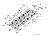
- the cleaning sheet 1C of the third embodiment has a plurality of long fibers 31 oriented substantially in one direction on at least one surface of the base sheet 2.
- This is a cleaning sheet 1 ⁇ / b> C in which long fiber bundles that are fiber bundles are joined by a plurality of fiber joining portions 32 that extend linearly in a direction that intersects the orientation direction of the long fibers 31.
- the plurality of fiber joint portions 32 of the cleaning sheet 1 ⁇ / b> C are arranged at a predetermined interval, and a plurality of long fibers 31 are arranged between the adjacent fiber joint portions 32, 32. It has been cut with.
- the cleaning sheet 1 ⁇ / b> C forms two discontinuous lines 26 a and 26 b in parallel in which linear cut portions 24 and uncut portions 25 are alternately arranged.
- the two discontinuous lines 26 a and 26 b are continuous as viewed from the orientation direction of the long fibers 31.
- the base sheet 2 has a rectangular shape as shown in FIGS. 9 and 10, the length of the base sheet 2 is 10 cm to 60 cm, and the width of the base sheet 2 is 5 cm to 40 cm. .
- long fibers 31 are arranged on both surfaces of the base material sheet 2 via fiber bonding portions 32.
- the long fibers 31 are usually oriented in the conveying direction of the material during production.
- “the long fibers 31 are substantially oriented in one direction” means that the orientation direction of some of the long fibers 31 is different due to manufacturing errors, crimp processing of the long fibers 31, etc. This means that the case where it deviates from the orientation direction of most of the long fibers 31 is not excluded.
- a large number of the long fibers 31 are orthogonal to the orientation direction of the long fibers 31 on both surfaces of the base sheet 2 as shown in FIGS. It arrange
- the orientation direction of the long fibers 31 coincides with the width direction of the base sheet 2.
- a large number of long fibers 31 are uniformly distributed over both longitudinal ends of the base sheet 2 as shown in FIGS. 9 and 10.
- the base sheet 2 is disposed over 50% to 90% of the width.
- the width of the base sheet 2 is wider than the range in which the long fibers 31 are arranged, and is an area outward in the width direction from the long fibers 31 in the base sheet 2 (hereinafter referred to as “flap 22”). ) Is a portion used when being mounted on the head portion of the cleaning tool (details will be described later).
- the long fibers 31 are preferably provided at 1000 to 50000 on one side per 1 cm of the base sheet 2. More preferably, 40,000 are provided.
- the long fibers 31 are used in a fiber aggregate (tow) state. It is preferable that the fiber assembly (tow) is sufficiently opened using a known opening device. Further, the thickness of the long fiber 31 is not particularly critical, but is preferably 0.1 to 200 dtex, particularly 2 to 30 dtex, from the viewpoint of dust entanglement and prevention of damage to the surface to be cleaned. preferable. Moreover, it is preferable to use a crimpable fiber as the long fiber 31 because dust entanglement is further improved. In addition, as the long fibers 31, those having a color other than white (for example, orange or light blue) can also be used in order to improve the appearance as a product and improve the visibility of attached dirt.
- a color other than white for example, orange or light blue
- the fiber joint portion 32 is for making a large number of long fibers 31 into a long fiber bundle.
- the long fiber bundle 3 is formed and the long fiber bundle 3 is formed into a base sheet. 2 is bonded on the surface.
- the fiber bonding portion 32 is formed by heat fusion or a hot melt adhesive, and in this embodiment, is formed by heat fusion.
- the number of the fiber bonding portions 32 of the cleaning sheet 1C of the present embodiment is preferably 2 to 30.
- the cleaning sheet 1C of the present embodiment having two fiber bonding portions 32 is illustrated in the drawings. Will be described with reference to FIG. In this embodiment, as shown in FIGS. 9 and 10, the two fiber bonding portions 32 and 32 are respectively in the direction orthogonal to the orientation direction of the long fibers 31, that is, both longitudinal ends of the base sheet 2. It is formed in one continuous straight line.
- each of the fiber joint portions 32 is the same as the length of the base sheet 2 as shown in FIGS. 9 and 10, and the width of the fiber joint portion 32 is as shown in FIGS. 0.5 mm to 10 mm.
- the two adjacent fiber joint portions 32, 32 are arranged at a predetermined interval, and the interval is preferably 1 mm to 50 mm, more preferably 10 mm to 40 mm from the viewpoint of the degree of freedom of the fibers. is there.
- the cleaning sheet 1 ⁇ / b> C forms the long fiber 31 and the base sheet 2 at the same position as the long fiber 31 in the middle portion 32 a of the two fiber joint portions 32 and 32. It is obtained by cutting with the shape cut portion 24.
- the intermediate portion 32a is located approximately in the middle of the adjacent fiber joint portions 32, 32, and has a width of 1 cm to 10 cm.
- the plurality of linear cut portions 24 are, as shown in FIGS. 9 and 10, two parallel discontinuous linear shapes in which discontinuous portions 25 are alternately arranged in the longitudinal direction of the base sheet 2, It is arranged in a so-called zigzag shape. As shown in FIGS. 9 and 10, the plurality of linear cut portions 24 are arranged in a zigzag shape in the longitudinal direction of the base sheet 2, and as a whole, from the two linear cut portions 24 group. Discontinuous lines 26a and 26b are formed. Each of the two discontinuous lines 26a and 26b is discontinuous in a plan view as shown in FIGS. 10 and 12, but when viewed from the orientation direction of the long fibers 31, one continuous line is formed. is doing.
- the two fiber joint portions 32 and 32 are arranged.
- the long fibers 31 in between can be cut reliably.
- the distance d1 between the linear cut part 24 constituting the discontinuous line 26a and the linear cut part 24 constituting another discontinuous line 26b adjacent thereto is determined from the viewpoint of the fiber length and the strength of the base sheet.
- the thickness is preferably 1 mm to 50 mm, more preferably 5 mm to 30 mm.
- the length l1 of each of the linear cut portions 24 is 5 mm to 50 mm as shown in FIG.
- the long fiber length of the long fiber 31 is preferably 20 to 50 mm, more preferably 20 to 30 mm.
- the short fiber length of the long fiber 31 is preferably 10 to 25 mm, More preferably, it is 10 to 20 mm.
- the fiber length of the long fiber 31 is the length from the fiber bonding portion 32 to the tip of the long fiber 31.
- the fiber lengths of the long fibers 31 located on both outer sides in the width direction of the cleaning sheet 1C are more than entangled with dust than the two fiber joint portions 32, 32 of the cleaning sheet 1C of the third embodiment.
- the thickness is preferably 10 to 150 mm, more preferably 30 to 120 mm.
- the said base material sheet 2 has a softness
- the base material sheet 2 and the long fiber 31 the thing similar to what was demonstrated in 1 A of cleaning sheets of 1st Embodiment can be used.
- the longitudinal direction of the base sheet 2 and the longitudinal direction of the head part 41 of the cleaning tool 4 are the same direction, and the central point of the base sheet 2 and the central part of the head part 41 Are attached to the mounting surface (bottom surface) of the head portion 41.
- the flaps 22 and 22 in the base material sheet 2 are folded back to the upper surface side of the head portion 41. Further, the flap 22 is pushed into a plurality of flexible sheet holding portions 44 having radial slits in the head portion 41. Accordingly, the cleaning sheet 1 ⁇ / b> C can be fixed to the head portion 41 of the cleaning tool 4.
- the cleaning sheet 1 ⁇ / b> C of the present embodiment can be used for, for example, floor cleaning. Therefore, the orientation direction of the long fibers 31 coinciding with the width direction of the base sheet 2 is substantially oriented in the cleaning direction of the cleaning tool 30.
- the cleaning sheet 1 ⁇ / b> C of the third embodiment in the state of being mounted on the head portion 41 of the cleaning tool 4, as with a normal mop cleaning tool, it is used for cleaning such as sweeping (floor cleaning) of a flooring room. be able to.
- the cleaning sheet 1C of the third embodiment as shown in FIGS. 9 to 11, the long fibers 31 between the adjacent fiber joint portions 32, 32 form two discontinuous lines in parallel, and are long. Since it is cut by a plurality of linear cut portions 24 extending so as to form one continuous line as viewed from the fiber orientation direction, it is surely cut. Therefore, the long fiber 31 is not restrained by the fiber joint part 32, and the dust collection property of the cleaning sheet 1C is improved. In addition, the long fibers 31 are not easily caught on the object to be cleaned.
- the cleaning sheet 1C of the third embodiment has a plurality of linear shapes in which long fibers 31 between adjacent fiber joint portions 32, 32 are formed in a staggered manner. It is cut by the cut portion 24. Therefore, one or the other of the adjacent fiber bonded portions 32 and 32 includes long fibers 31 having two types of fiber lengths, a longer fiber length and a shorter fiber length. These two types of fiber lengths are different from the fiber lengths of the long fibers 31 located on both outer sides in the width direction of the cleaning sheet 1C, rather than the fiber joint portions 32, 32.
- the fiber lengths of the long fibers 31 included in one or the other of the fiber joint portions 32 and 32 are not uniform but have three types of fiber lengths, and are random, so that the dust collection property is improved. Can do. Moreover, after cutting by the linear cut part 24, the long fiber 31 which has three types of fiber lengths is randomly raised in the three-dimensional direction, so that the fiber length of the long fiber 31 becomes further random, and dust collection The property is further improved.
- a cleaning sheet according to a fourth embodiment of the present invention will be described with reference to FIG. About cleaning sheet 1D of 4th Embodiment, a different point from cleaning sheet 1C of 3rd Embodiment is demonstrated. The points that are not particularly described are the same as the cleaning sheet 1C of the third embodiment, and the description of the cleaning sheet 1C of the third embodiment is applied as appropriate.
- the number of the fiber joint portions 32 of the cleaning sheet 1D of the fourth embodiment is three, and the three fiber joint portions 32, 32, and 31 are each oriented in the orientation direction of the long fibers 31, as shown in FIG. Is formed in one continuous straight line in the direction orthogonal to the longitudinal direction of the base sheet 2.
- the linear cut portions 24 of the cleaning sheet 1D of the fourth embodiment are arranged in a zigzag shape and are two discontinuous like the linear cut portions 24 of the cleaning sheet 1C of the third embodiment.
- the lines 26a and 26b are formed, the two discontinuous lines 26a and 26b of the cleaning sheet 1D of the fourth embodiment are in a direction orthogonal to the orientation direction of the long fibers 31, as shown in FIG. Two sets are formed. In each of the two sets of discontinuous lines 26a and 26b, the formation position of one of the discontinuous lines 26a and 26b is different from the formation position of the other discontinuous lines 26a and 26b at the position of the intermediate portion 32a between the fiber bonded portions. As shown in FIG.
- the cleaning sheet 1D of the fourth embodiment similarly to the cleaning sheet 1C of the third embodiment, the flooring room can be used for cleaning such as sweeping (floor cleaning).
- the cleaning sheet 1D of the fourth embodiment can obtain the same effects as the cleaning sheet 1C of the third embodiment. That is, the cleaning sheet 1D of the fourth embodiment forms two discontinuous lines that are parallel to each other, as in the cleaning sheet 1C of the third embodiment, and is continuous when viewed from the orientation direction of the long fibers.
- the cleaning sheet 1D of the fourth embodiment includes two sets of two discontinuous lines 26a and 26b, and the formation positions of the long fibers 31 are different from each other. Compared with the cleaning sheet 1C, the randomness is further improved, and the dust collecting property can be further enhanced.
- a cleaning sheet according to a fifth embodiment of the present invention will be described with reference to FIG. About the cleaning sheet 1E of 5th Embodiment, a different point from the cleaning sheet 1C of 3rd Embodiment is demonstrated. The points that are not particularly described are the same as the cleaning sheet 1C of the third embodiment, and the description of the cleaning sheet 1C of the third embodiment is applied as appropriate.
- the plurality of fiber bonding portions 32 ′ of the cleaning sheet 1 ⁇ / b> E of the fifth embodiment are in a direction orthogonal to the orientation direction of the long fibers 31, that is, in the longitudinal direction of the base sheet 2.
- the discontinuous portions 33 are formed in two discontinuous linear shapes (so-called zigzag) that are alternately arranged and form a fiber joint portion group as a whole.
- the two fiber junction part groups 34a and 34b are provided.
- the plurality of fiber joint portions 32 ′ of the cleaning sheet 1 ⁇ / b> E of the fifth embodiment form another fiber joint portion group 34 a and 34 b when viewed from the width direction of the base sheet 2.
- the ends of adjacent fiber joint portions 32 'and 32' overlap each other.
- the end of the fiber joint portion 32 ′ constituting the fiber joint portion group 34 a and the end of the fiber joint portion 32 ′ constituting another fiber joint portion group 34 b adjacent to it overlap each other.
- the interval w2 is preferably 0 mm to 10 mm, and more preferably 0 mm to 5 mm.
- the distance d2 between the fiber joint portion 32 ′ constituting the fiber joint portion group 34a and the fiber joint portion 32 ′ constituting another fiber joint portion group 34b adjacent to the fiber joint portion group 34a is 5 mm or more from the viewpoint of the strength of the fiber joint portion. It is preferably 50 mm, and more preferably 10 mm to 40 mm. Further, the length l2 of each of the fiber joined portions 32 'is 5 mm to 50 mm as shown in FIG.
- the cleaning sheet 1E of the fifth embodiment which explains the operational effects when using the cleaning sheet 1C of the fifth embodiment of the present invention described above, similarly to the cleaning sheet 1C of the third embodiment,
- the flooring room can be used for cleaning such as sweeping (floor cleaning).
- the cleaning sheet 1E of the fifth embodiment can obtain the same effects as the cleaning sheet 1C of the third embodiment. That is, the cleaning sheet 1E of the fifth embodiment forms two discontinuous lines that are parallel to each other and is continuous as viewed from the orientation direction of the long fibers, like the cleaning sheet 1C of the third embodiment.
- the cleaning sheet 1E of the fifth embodiment includes a plurality of fiber joint portions 32 ′ formed in a staggered pattern, the fiber length of the long fibers 31 is the cleaning sheet 1C of the third embodiment. Compared to the above, the randomness is further improved, and the dust collecting property can be further enhanced.
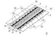
- a cleaning sheet according to a sixth embodiment of the present invention will be described with reference to FIG. Regarding the cleaning sheet 1F of the sixth embodiment, differences from the cleaning sheet 1C of the third embodiment will be described. The points that are not particularly described are the same as the cleaning sheet 1C of the third embodiment, and the description of the cleaning sheet 1C of the third embodiment is applied as appropriate.
- the fiber bonding portion 32 of the cleaning sheet 1 ⁇ / b> F of the sixth embodiment is for forming a long fiber bundle 3 in which a large number of long fibers 31 are gathered. It is a joining part that does not participate in joining with the material sheet 2, and the joining between the long fibers 31 constituting the long fiber bundle 3 and the base sheet 2 is joined via the sheet joining part 21.
- the plurality of sheet bonding portions 21 of the cleaning sheet 1 ⁇ / b> F of the sixth embodiment are intermittently disposed on the fiber bonding portions 32 in a direction intersecting with the orientation direction of the long fibers 31.
- the sheet joining portion group 23 is formed.
- the linear cut portions 24 of the cleaning sheet 1 ⁇ / b> F according to the sixth embodiment are disposed in the middle portion of the two rows of sheet joining portion groups 23.
- the cleaning sheet 1F of the sixth embodiment similarly to the cleaning sheet 1C of the third embodiment, In a state of being mounted on the head portion 41 of the cleaning tool 4, the flooring room can be used for cleaning such as sweeping (floor cleaning).
- the cleaning sheet 1F of the sixth embodiment has the same effects as the cleaning sheet 1C of the third embodiment. That is, the cleaning sheet 1F of the sixth embodiment, like the cleaning sheet 1C of the third embodiment, forms two discontinuous lines in parallel and is continuous when viewed from the orientation direction of the long fibers.
- the long fibers 31 between the adjacent fiber joint portions 32 and 32 are surely cut and caught on the object to be cleaned. hard. Moreover, the fiber length of the long fiber 31 becomes random and can improve dust collection property.
- the cleaning sheet of the present invention is not limited to the cleaning sheets of the third to sixth embodiments described above, and can be changed as appropriate.
- the constituent requirements of the cleaning sheets of the third to sixth embodiments described above can be appropriately combined and implemented within a range that does not impair the gist of the present invention.
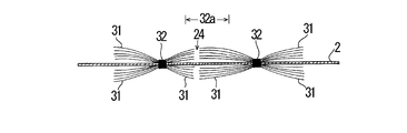
- the long fiber 31 and the base sheet 2 at the same position as the long fiber 31 are linearly formed as shown in FIG. Although it cuts by the cut part 24, as shown in FIG. 17, only the long fiber 31 may be cut.
- the fiber joint portions 32 and 32 are used. 'Extends in a direction orthogonal to the orientation direction of the long fibers 31, but it only needs to intersect the orientation direction of the long fibers 31.
- the orientation direction of the long fibers 31 is long. Is formed so that the longitudinal direction of the base sheet 2 coincides with the longitudinal direction of the base sheet 2, but it does not have to coincide with the longitudinal direction of the base sheet 2.
- the cut portion 24 is formed in the intermediate portion 32a that is located approximately in the middle of the adjacent fiber joint portions 32 and 32. However, what is necessary is just between the fiber joint parts 32 and 32 which adjoin.
- the lengths of the cut portions 24 may not be the same length.
- Example 1 The cleaning sheet shown in FIG. 1 or FIG. 2 was produced.
- the long fiber 31 constituting the long fiber bundle 3 a core-sheath type heat-fusible composite fiber having a core of polyethylene terephthalate and a sheath of polyethylene having a thickness of 2.2 dtex was used.
- One fiber joint so that the long fibers 31 do not fall apart and extend in the center in the width direction of the long fiber bundle 3 over the entire length in the longitudinal direction (direction perpendicular to the orientation direction of the long fibers 31).
- the portion 32 is applied and joined.
- the width of the fiber joint portion 32 is 3 mm.
- the bonding method of the fiber bonding portion 32 is a heat fusion method.
- the width direction of the long fiber bundle 3 coincides with the orientation direction of the long fibers 31.
- the long fiber bundle 3 is maintained in the aggregated state of the long fibers 31 in a state where the long fiber bundle 3 is not bonded to the base sheet 2 by the fiber bonding portion 32 extending in the longitudinal direction of the long fiber bundle 3.
- An air-through nonwoven fabric having a basis weight of 40 g / m 2 was used as the base sheet 2.
- the constituent fiber was a core-sheath type heat-fusible conjugate fiber (2.2 dtex ⁇ 51 mm) having a core made of polyethylene terephthalate and a sheath made of polyethylene.
- the dimension of the base sheet 2 was length: 285 mm ⁇ width: 205 mm.
- Example 2 The second embodiment is the same as the first embodiment except that the interval between the adjacent sheet joining portions 21 is changed as compared to the first embodiment.
- seat junction parts 21 of Example 2 is 40 mm.
- Example 3 Similar to the second embodiment, the third embodiment is the same as the first embodiment except that the interval between adjacent sheet joining portions 21 is changed.
- seat junction parts 21 of Example 3 is 10 mm.
- Comparative Example 1 In Comparative Example 1, as compared with Example 1, the sheet bonding portion 21 is not intermittently formed in a direction orthogonal to the orientation direction of the long fibers 31, and the fiber bonding portion 32 is formed on the fiber bonding portion 32. 32 and a straight line continuous in the same direction.
- the sheet joining portion 21 and the fiber joining portion 32 are the same shape and size and are formed at the same position. The rest is the same as in Example 1.
- Comparative Example 2 Comparative Example 2 is the same as Example 1 except that the interval between adjacent sheet joining portions 21 is changed as compared to Example 1.
- interval of the adjacent sheet junction parts 21 of the comparative example 2 is 5 mm.
- Comparative Example 3 Comparative Example 3 is the same as Example 1 except that the interval between adjacent sheet joining portions 21 is changed as compared to Example 1.
- interval of the adjacent sheet junction parts 21 of the comparative example 3 is 50 mm.
- Example 4 A cleaning sheet shown in FIG. 9 or 10 was produced.
- the long fiber 31 constituting the long fiber bundle 3 a core-sheath type heat-fusible composite fiber having a core of polyethylene terephthalate and a sheath of polyethylene having a thickness of 2.2 dtex was used.
- the long fibers 31 are bonded to the base sheet 2 via the two fiber bonding portions 32 and 32 so that the long fibers 31 do not fall apart.
- Each of the two fiber bonded portions 32, 32 is formed in one continuous linear shape so as to extend over the entire length of the base sheet 2 in the longitudinal direction (direction orthogonal to the orientation direction of the long fibers 31). ing.
- variety of each fiber junction part 32 is 3 mm.
- the interval between the two adjacent fiber joint portions 32, 32 is 8 cm.
- the joining method of the fiber joining part 32 is a heat sealing
- the width direction of the long fiber bundle 3 coincides with the orientation direction of the long fibers 31.
- An air-through nonwoven fabric having a basis weight of 40 g / m 2 was used as the base sheet 2.
- the constituent fiber was a core-sheath type heat-fusible conjugate fiber (2.2 dtex ⁇ 51 mm) having a core made of polyethylene terephthalate and a sheath made of polyethylene.
- the dimension of the base sheet 2 was length: 285 mm ⁇ width: 205 mm.
- the long fibers 31 and the base sheet 2 were cut by a plurality of linear cut portions 24 to form the cleaning sheet of Example 4.
- the plurality of linear cut portions 24 arranged in a staggered pattern has an overlap interval w of 0.1 mm between adjacent linear cut portions 24 and a distance d between adjacent linear cut portions 24 of 30 mm. Each portion 24 is formed so that the length l thereof is 40 mm.
- Example 5 The fifth embodiment is the same as the fourth embodiment except that the overlap interval w between the adjacent linear cut portions 24 is changed as compared to the fourth embodiment.
- the overlap interval w between the adjacent linear cut portions 24 of Example 5 is 0.5 mm.
- Example 6 The sixth embodiment is the same as the fourth embodiment except that the overlapping interval w between the adjacent linear cut portions 24 is changed as in the fifth embodiment.
- the overlap interval w between the adjacent linear cut portions 24 in Example 6 is 2.0 mm.
- Example 7 The seventh embodiment is the same as the fourth embodiment except that the overlapping interval w between the adjacent linear cut portions 24 is changed as in the fifth and sixth embodiments.
- the overlapping interval w between the adjacent linear cut portions 24 of Example 7 is 0 mm.
- Comparative Example 4 In Comparative Example 4, the long fibers 31 and the base sheet 2 are not cut as compared with Example 4. The rest is the same as in Example 4.
- Comparative Example 5 In Comparative Example 5, as compared with Example 4, the long fibers 31 and the base sheet 2 are not cut by the plurality of linear cut portions 24 arranged in a staggered shape, and one continuous straight line The long fibers 31 and the base material sheet 2 are cut with a cut line. The rest is the same as in Example 4.
- Comparative Example 6 Compared to Example 4, Comparative Example 6 does not cut the long fibers 31 and the base sheet 2 by a plurality of linear cut portions 24 arranged in a staggered pattern, but a single continuous straight line. The long fibers 31 are cut with a cut line. Further, the base sheet 2 is not cut, and only the long fibers 31 are cut by the plurality of linear cut portions 24. The rest is the same as in Example 4.
- the cleaning sheet of Comparative Example 4 does not cut the long fibers 31 between two adjacent fiber joints, the degree of freedom of the long fibers 31 is limited, the dust collecting property is poor, and the long fibers 31 was easily caught on the object to be cleaned.
- the cleaning sheet of Comparative Example 5 is evaluated as a cleaning sheet because not only the long fibers 31 between two adjacent fiber joints but also the base sheet 2 is cut with a straight cut line. could not.
- the cleaning sheet of Comparative Example 6 was inferior to the cleaning sheets of Examples 4 to 7 in terms of dust collection, which is the highest priority function of the cleaning sheet.
- the base sheet 2 is not cut and only the long fibers 31 between two adjacent fiber joints are cut by a cut line extending in a straight line, it is very difficult to make.
- the degree of freedom of the long-fiber bundle is not limited by the joint portion for joining the heat-fusible long fiber and the heat-fusible sheet, and the degree of freedom of the heat-fusible long fiber is improved. , Can improve garbage collection. Moreover, according to the manufacturing method of this invention, this cleaning sheet can be manufactured easily.
- the degree of freedom of the heat-fusible long fiber is not limited by the joining portion for joining the heat-fusible long fiber and the heat-fusible sheet, and the heat-fusible long fiber is to be cleaned. It is difficult to get caught in things. Further, since the length from the welded portion to the tip of the heat-fusible long fiber is random, it is possible to improve dust collection.
Landscapes
- Engineering & Computer Science (AREA)
- Textile Engineering (AREA)
- Cleaning Implements For Floors, Carpets, Furniture, Walls, And The Like (AREA)
Abstract
Priority Applications (6)
| Application Number | Priority Date | Filing Date | Title |
|---|---|---|---|
| AU2009237048A AU2009237048B2 (en) | 2008-04-16 | 2009-04-09 | Cleaning sheet and process for producing the same |
| CA2721340A CA2721340C (fr) | 2008-04-16 | 2009-04-09 | Feuille de nettoyage et son procede de production |
| US12/988,224 US9113768B2 (en) | 2008-04-16 | 2009-04-09 | Cleaning sheet and process for producing the same |
| CN200980113391.5A CN102006812B (zh) | 2008-04-16 | 2009-04-09 | 清扫用片材及其制造方法 |
| MYPI2010004773A MY175164A (en) | 2008-04-16 | 2009-04-09 | Cleaning sheet and process for producing the same |
| EP09732197.0A EP2283758B1 (fr) | 2008-04-16 | 2009-04-09 | Feuille de nettoyage et son procédé de production |
Applications Claiming Priority (4)
| Application Number | Priority Date | Filing Date | Title |
|---|---|---|---|
| JP2008106357A JP5231854B2 (ja) | 2008-04-16 | 2008-04-16 | 清掃用シート及びその製造方法 |
| JP2008-106357 | 2008-04-16 | ||
| JP2008-152015 | 2008-06-10 | ||
| JP2008152015A JP5241334B2 (ja) | 2008-06-10 | 2008-06-10 | 清掃用シート |
Publications (1)
| Publication Number | Publication Date |
|---|---|
| WO2009128381A1 true WO2009128381A1 (fr) | 2009-10-22 |
Family
ID=41199078
Family Applications (1)
| Application Number | Title | Priority Date | Filing Date |
|---|---|---|---|
| PCT/JP2009/057248 Ceased WO2009128381A1 (fr) | 2008-04-16 | 2009-04-09 | Feuille de nettoyage et son procédé de production |
Country Status (8)
| Country | Link |
|---|---|
| US (1) | US9113768B2 (fr) |
| EP (1) | EP2283758B1 (fr) |
| KR (1) | KR101585636B1 (fr) |
| CN (1) | CN102006812B (fr) |
| AU (1) | AU2009237048B2 (fr) |
| CA (1) | CA2721340C (fr) |
| MY (1) | MY175164A (fr) |
| WO (1) | WO2009128381A1 (fr) |
Cited By (1)
| Publication number | Priority date | Publication date | Assignee | Title |
|---|---|---|---|---|
| WO2013105469A1 (fr) * | 2012-01-10 | 2013-07-18 | ユニ・チャーム株式会社 | Dispositif de fabrication d'organe de bande de nettoyage et son procédé de fabrication |
Families Citing this family (33)
| Publication number | Priority date | Publication date | Assignee | Title |
|---|---|---|---|---|
| US10952587B2 (en) * | 2010-04-16 | 2021-03-23 | Unger Marketing International, Llc | Dusting devices |
| GB2504342B (en) * | 2012-07-26 | 2015-06-10 | Ronald Alexander Scot Young | Mop material, a mop pad, a mop, and a method of manufacturing mop material |
| WO2014104325A1 (fr) | 2012-12-29 | 2014-07-03 | ユニ・チャーム株式会社 | Procédé et système de production d'élément de nettoyage |
| JP6047401B2 (ja) | 2012-12-29 | 2016-12-21 | ユニ・チャーム株式会社 | 開繊された繊維束の製造方法、清掃部材の製造方法、繊維束の開繊装置、及び清掃部材の製造システム |
| US20140182767A1 (en) | 2012-12-29 | 2014-07-03 | Unicharm Corporation | Method of producing cleaning member |
| US20140187406A1 (en) | 2012-12-29 | 2014-07-03 | Unicharm Corporation | Method of producing cleaning member |
| DE102013006191B3 (de) * | 2013-04-11 | 2014-10-02 | Carl Freudenberg Kg | Verfahren zur Herstellung eines Reinigungstextils |
| USD765931S1 (en) * | 2014-10-20 | 2016-09-06 | Rubbermaid Commercial Products, Llc | String mop headband |
| EP3078316B1 (fr) * | 2015-04-09 | 2019-11-20 | The Procter and Gamble Company | Article de nettoyage ayant des liaisons d'étanchéité discrètes |
| DE102017115027B4 (de) * | 2017-07-05 | 2024-10-02 | Vorwerk & Co. Interholding Gmbh | Reinigungstuch für eine Reinigungseinrichtung und Reinigungseinrichtung mit einem Reinigungstuch |
| US11253128B2 (en) | 2017-09-11 | 2022-02-22 | The Procter & Gamble Company | Cleaning article with differential pitch tow tufts |
| US11045061B2 (en) | 2017-09-11 | 2021-06-29 | The Procter & Gamble Company | Method of making a tufted laminated cleaning article |
| US11950737B2 (en) | 2017-09-11 | 2024-04-09 | The Procter & Gamble Company | Cleaning article with irregularly spaced tow tufts |
| US10730081B2 (en) | 2017-09-11 | 2020-08-04 | The Procter & Gamble Company | Method of making a cleaning article having cutouts |
| EP3453305B1 (fr) | 2017-09-11 | 2022-11-02 | The Procter & Gamble Company | Procédé de fabrication d'un article de nettoyage laminé touffeté |
| US10722091B2 (en) | 2017-10-06 | 2020-07-28 | The Procter & Gamble Company | Cleaning article with preferentially coated tow fibers |
| US10653286B2 (en) | 2017-10-06 | 2020-05-19 | The Procter & Gamble Company | Cleaning article with preferential coating |
| US11903542B2 (en) | 2018-04-03 | 2024-02-20 | The Procter & Gamble Company | Cleaning article with double bonded tow tufts |
| US12082760B2 (en) | 2018-04-03 | 2024-09-10 | The Procter & Gamble Company | Cleaning article with irregularly spaced tow tufts |
| US11375867B2 (en) | 2018-04-03 | 2022-07-05 | The Procter & Gamble Company | Cleaning article with differential sized tow tufts |
| JP2023518022A (ja) | 2020-04-10 | 2023-04-27 | ザ プロクター アンド ギャンブル カンパニー | 剃毛に使用するための流動性固体組成物 |
| WO2021207442A1 (fr) | 2020-04-10 | 2021-10-14 | The Procter & Gamble Company | Composition orale solide rhéologique |
| US12138333B2 (en) | 2020-04-10 | 2024-11-12 | The Procter & Gamble Company | Rheological solid composition for use in personal care compositions |
| WO2021207438A1 (fr) | 2020-04-10 | 2021-10-14 | The Procter & Gamble Company | Produit de soin buccal comprenant une composition solide rhéologique |
| WO2021216288A1 (fr) | 2020-04-10 | 2021-10-28 | The Procter & Gamble Company | Outil de nettoyage avec une composition solide rhéologique |
| US12122979B2 (en) | 2020-04-10 | 2024-10-22 | The Procter & Gamble Company | Cleaning article with preferential rheological solid composition |
| WO2021207439A1 (fr) | 2020-04-10 | 2021-10-14 | The Procter & Gamble Company | Composition solide rhéologique |
| EP4133047B1 (fr) | 2020-04-10 | 2026-02-11 | The Procter & Gamble Company | Article de nettoyage ayant une composition solide rhéologique préférentielle |
| CN111374616A (zh) * | 2020-05-09 | 2020-07-07 | 杭州汇海机械有限公司 | 超柔软高蓬松除尘掸 |
| WO2022082192A1 (fr) | 2020-10-16 | 2022-04-21 | The Procter & Gamble Company | Article de nettoyage à revêtement préférentiel |
| US11833237B2 (en) | 2021-03-09 | 2023-12-05 | The Procter & Gamble Company | Method for enhancing scalp active deposition |
| EP4349233B1 (fr) * | 2022-10-06 | 2025-08-13 | The Procter & Gamble Company | Procédé d'emballage d'une lingette nettoyante |
| EP4349230A1 (fr) | 2022-10-06 | 2024-04-10 | The Procter & Gamble Company | Chiffon de nettoyage |
Citations (6)
| Publication number | Priority date | Publication date | Assignee | Title |
|---|---|---|---|---|
| EP0777997A2 (fr) | 1995-12-01 | 1997-06-11 | Uni-Charm Corporation | Procédé pour la fabrication d'un dispositif d'essuyage jetable |
| JP2000245670A (ja) | 1999-03-04 | 2000-09-12 | Uni Charm Corp | 清掃用シート及びその製造方法 |
| US6329308B1 (en) | 1995-11-17 | 2001-12-11 | Uni-Charm Corporation | Disposable wipe-off article |
| JP3107183U (ja) * | 2004-08-12 | 2005-01-27 | 王子ネピア株式会社 | 清掃用複合シート |
| JP2006230536A (ja) * | 2005-02-23 | 2006-09-07 | Yamazaki Corp | 払拭材 |
| JP2007289341A (ja) * | 2006-04-24 | 2007-11-08 | Yamada Chiyoe | 清掃シート |
Family Cites Families (39)
| Publication number | Priority date | Publication date | Assignee | Title |
|---|---|---|---|---|
| US5143393A (en) * | 1991-03-19 | 1992-09-01 | Una-Goose Company, Inc. | Gooseneck trailer mounting ball installation for pick-up truck |
| JP3107183B2 (ja) * | 1993-12-27 | 2000-11-06 | 株式会社ニレコ | 溶融金属の変位測定方法および装置 |
| JP3771325B2 (ja) | 1996-06-20 | 2006-04-26 | ユニ・チャーム株式会社 | 使い捨ての汚れ拭き取り材 |
| US6143393A (en) | 1997-12-16 | 2000-11-07 | Uni-Charm Corporation | Cleaning product and production process therefor |
| JP3100578B2 (ja) | 1997-12-16 | 2000-10-16 | ユニ・チャーム株式会社 | 清掃用物品及びその製造方法 |
| US6716514B2 (en) * | 1998-01-26 | 2004-04-06 | The Procter & Gamble Company | Disposable article with enhanced texture |
| US6180214B1 (en) * | 1998-01-26 | 2001-01-30 | The Procter & Gamble Company | Wiping article which exhibits differential wet extensibility characteristics |
| JP3642944B2 (ja) | 1998-03-19 | 2005-04-27 | ユニ・チャーム株式会社 | 長繊維を利用した清掃用物品 |
| JP3558892B2 (ja) * | 1998-09-24 | 2004-08-25 | ユニ・チャーム株式会社 | 清掃用シート |
| JP3668630B2 (ja) | 1999-02-26 | 2005-07-06 | ユニ・チャーム株式会社 | 清掃用シート |
| JP2000296084A (ja) * | 1999-04-13 | 2000-10-24 | Uni Charm Corp | 使い捨て拭き取り用具およびその製造方法 |
| US20020042962A1 (en) * | 2000-02-24 | 2002-04-18 | Willman Kenneth William | Cleaning sheets comprising a polymeric additive to improve particulate pick-up and minimize residue left on surfaces and cleaning implements for use with cleaning sheets |
| CN1184922C (zh) * | 2000-07-10 | 2005-01-19 | 尤妮佳股份有限公司 | 清扫物品 |
| EP1212972B1 (fr) | 2000-10-13 | 2015-12-09 | Kao Corporation | Feuille de nettoyage pour nettoyer des surfaces veloutées |
| IL152340A (en) * | 2001-02-23 | 2007-12-03 | Yoshinori Tanaka | Cleaning article |
| US20030106568A1 (en) | 2001-12-12 | 2003-06-12 | Kimberly-Clark Worldwide, Inc. | Cleaning sheet, system and apparatus |
| CN1886083A (zh) * | 2004-04-01 | 2006-12-27 | 山田千代惠 | 清扫工具用片材及清扫工具 |
| WO2005099549A1 (fr) | 2004-04-01 | 2005-10-27 | Yamada, Chiyoe | Feuille d'outil de nettoyage et outil de nettoyage |
| JP4018690B2 (ja) | 2004-12-20 | 2007-12-05 | ユニ・チャーム株式会社 | 長繊維を利用した清掃用物品 |
| CA2561362C (fr) | 2004-12-27 | 2012-01-17 | Yamada, Chiyoe | Dispositif de nettoyage et procede de fabrication idoine |
| US7566671B2 (en) * | 2005-01-28 | 2009-07-28 | S.C. Johnson & Son, Inc. | Cleaning or dusting pad |
| ES2388746T3 (es) * | 2005-10-19 | 2012-10-18 | Kao Corporation | Utensilio de limpieza |
| JP4845525B2 (ja) * | 2006-02-08 | 2011-12-28 | ユニ・チャーム株式会社 | 清掃体及び清掃用具 |
| ES2397856T3 (es) * | 2006-03-09 | 2013-03-11 | Kao Corporation | Artículo de limpieza y método de producción |
| JP4859490B2 (ja) * | 2006-03-09 | 2012-01-25 | 花王株式会社 | 清掃用物品 |
| JP5048274B2 (ja) * | 2006-05-31 | 2012-10-17 | ユニ・チャーム株式会社 | 清掃体及び清掃用具 |
| JP3906260B2 (ja) | 2006-08-24 | 2007-04-18 | 株式会社東芝 | 情報記憶媒体とその情報記録方法及び装置と情報再生装置 |
| JP4709105B2 (ja) * | 2006-09-12 | 2011-06-22 | ユニ・チャーム株式会社 | 清掃体及び清掃用具 |
| JP5314432B2 (ja) | 2007-02-13 | 2013-10-16 | 大作 山田 | 清掃用シート |
| JP4823105B2 (ja) * | 2007-03-05 | 2011-11-24 | ユニ・チャーム株式会社 | 清掃用具及び清掃体 |
| JP5048375B2 (ja) * | 2007-03-30 | 2012-10-17 | ユニ・チャーム株式会社 | 清掃体及び清掃用具 |
| JP5235478B2 (ja) | 2007-04-27 | 2013-07-10 | 花王株式会社 | 清掃用シート |
| WO2008146821A1 (fr) | 2007-05-28 | 2008-12-04 | Kao Corporation | Feuille de nettoyage |
| JP5007218B2 (ja) | 2007-12-27 | 2012-08-22 | 花王株式会社 | 清掃用シート |
| JP5171347B2 (ja) * | 2008-03-31 | 2013-03-27 | ユニ・チャーム株式会社 | 清掃用具 |
| US8752232B2 (en) | 2009-02-13 | 2014-06-17 | Kao Corporation | Cleaning sheet |
| JP5436042B2 (ja) * | 2009-05-21 | 2014-03-05 | ユニ・チャーム株式会社 | 清掃体ホルダ、清掃用具 |
| JP5427628B2 (ja) * | 2010-02-03 | 2014-02-26 | ユニ・チャーム株式会社 | 清掃用具、清掃体 |
| US8148197B2 (en) * | 2010-07-27 | 2012-04-03 | Micron Technology, Inc. | Methods of forming germanium-antimony-tellurium materials and a method of forming a semiconductor device structure including the same |
-
2009
- 2009-04-09 MY MYPI2010004773A patent/MY175164A/en unknown
- 2009-04-09 EP EP09732197.0A patent/EP2283758B1/fr not_active Not-in-force
- 2009-04-09 CA CA2721340A patent/CA2721340C/fr active Active
- 2009-04-09 US US12/988,224 patent/US9113768B2/en not_active Expired - Fee Related
- 2009-04-09 KR KR1020107022859A patent/KR101585636B1/ko not_active Expired - Fee Related
- 2009-04-09 CN CN200980113391.5A patent/CN102006812B/zh active Active
- 2009-04-09 WO PCT/JP2009/057248 patent/WO2009128381A1/fr not_active Ceased
- 2009-04-09 AU AU2009237048A patent/AU2009237048B2/en not_active Ceased
Patent Citations (6)
| Publication number | Priority date | Publication date | Assignee | Title |
|---|---|---|---|---|
| US6329308B1 (en) | 1995-11-17 | 2001-12-11 | Uni-Charm Corporation | Disposable wipe-off article |
| EP0777997A2 (fr) | 1995-12-01 | 1997-06-11 | Uni-Charm Corporation | Procédé pour la fabrication d'un dispositif d'essuyage jetable |
| JP2000245670A (ja) | 1999-03-04 | 2000-09-12 | Uni Charm Corp | 清掃用シート及びその製造方法 |
| JP3107183U (ja) * | 2004-08-12 | 2005-01-27 | 王子ネピア株式会社 | 清掃用複合シート |
| JP2006230536A (ja) * | 2005-02-23 | 2006-09-07 | Yamazaki Corp | 払拭材 |
| JP2007289341A (ja) * | 2006-04-24 | 2007-11-08 | Yamada Chiyoe | 清掃シート |
Non-Patent Citations (1)
| Title |
|---|
| See also references of EP2283758A4 |
Cited By (3)
| Publication number | Priority date | Publication date | Assignee | Title |
|---|---|---|---|---|
| WO2013105469A1 (fr) * | 2012-01-10 | 2013-07-18 | ユニ・チャーム株式会社 | Dispositif de fabrication d'organe de bande de nettoyage et son procédé de fabrication |
| JP2013141498A (ja) * | 2012-01-10 | 2013-07-22 | Unicharm Corp | 清掃用ウエブ部材の製造装置、及び製造方法 |
| US9486991B2 (en) | 2012-01-10 | 2016-11-08 | Unicharm Corporation | Manufacturing apparatus and manufacturing method for cleaning web member |
Also Published As
| Publication number | Publication date |
|---|---|
| KR20100135256A (ko) | 2010-12-24 |
| US20110088189A1 (en) | 2011-04-21 |
| EP2283758B1 (fr) | 2018-08-08 |
| CN102006812A (zh) | 2011-04-06 |
| EP2283758A1 (fr) | 2011-02-16 |
| EP2283758A4 (fr) | 2016-11-16 |
| CA2721340C (fr) | 2016-01-12 |
| KR101585636B1 (ko) | 2016-01-14 |
| US9113768B2 (en) | 2015-08-25 |
| AU2009237048B2 (en) | 2014-09-25 |
| CN102006812B (zh) | 2014-08-06 |
| CA2721340A1 (fr) | 2009-10-22 |
| AU2009237048A1 (en) | 2009-10-22 |
| MY175164A (en) | 2020-06-11 |
Similar Documents
| Publication | Publication Date | Title |
|---|---|---|
| KR101585636B1 (ko) | 청소용 시트 및 그 제조방법 | |
| JP4543124B1 (ja) | 清掃用シート | |
| US8617685B2 (en) | Cleaning sheet | |
| JP5235478B2 (ja) | 清掃用シート | |
| JP5231854B2 (ja) | 清掃用シート及びその製造方法 | |
| JP3100578B2 (ja) | 清掃用物品及びその製造方法 | |
| AU9711898A (en) | Cleaning product and production process therefor | |
| JP4384448B2 (ja) | 清掃用物品およびその製造方法 | |
| JP2009142358A (ja) | 清掃シートおよび清掃用具 | |
| JP2008272147A (ja) | 清掃用シート及びその製造方法 | |
| JP5241334B2 (ja) | 清掃用シート | |
| JP5912256B2 (ja) | 清掃用具および清掃用物品 | |
| JP2014050558A (ja) | 清掃用シート | |
| JP2022117902A (ja) | 清掃用シート | |
| JP2020044099A (ja) | 清掃用物品及びその製造方法 |
Legal Events
| Date | Code | Title | Description |
|---|---|---|---|
| WWE | Wipo information: entry into national phase |
Ref document number: 200980113391.5 Country of ref document: CN |
|
| 121 | Ep: the epo has been informed by wipo that ep was designated in this application |
Ref document number: 09732197 Country of ref document: EP Kind code of ref document: A1 |
|
| ENP | Entry into the national phase |
Ref document number: 20107022859 Country of ref document: KR Kind code of ref document: A |
|
| WWE | Wipo information: entry into national phase |
Ref document number: 2721340 Country of ref document: CA |
|
| NENP | Non-entry into the national phase |
Ref country code: DE |
|
| WWE | Wipo information: entry into national phase |
Ref document number: 2009732197 Country of ref document: EP |
|
| WWE | Wipo information: entry into national phase |
Ref document number: 2009237048 Country of ref document: AU |
|
| ENP | Entry into the national phase |
Ref document number: 2009237048 Country of ref document: AU Date of ref document: 20090409 Kind code of ref document: A |
|
| WWE | Wipo information: entry into national phase |
Ref document number: 12988224 Country of ref document: US |