WO2009130953A1 - Equipement de test par vibrations électrodynamiques - Google Patents
Equipement de test par vibrations électrodynamiques Download PDFInfo
- Publication number
- WO2009130953A1 WO2009130953A1 PCT/JP2009/054616 JP2009054616W WO2009130953A1 WO 2009130953 A1 WO2009130953 A1 WO 2009130953A1 JP 2009054616 W JP2009054616 W JP 2009054616W WO 2009130953 A1 WO2009130953 A1 WO 2009130953A1
- Authority
- WO
- WIPO (PCT)
- Prior art keywords
- electrodynamic
- rail
- actuator
- intermediate stage
- runner block
- Prior art date
- Legal status (The legal status is an assumption and is not a legal conclusion. Google has not performed a legal analysis and makes no representation as to the accuracy of the status listed.)
- Ceased
Links
Images






Classifications
-
- G—PHYSICS
- G01—MEASURING; TESTING
- G01M—TESTING STATIC OR DYNAMIC BALANCE OF MACHINES OR STRUCTURES; TESTING OF STRUCTURES OR APPARATUS, NOT OTHERWISE PROVIDED FOR
- G01M7/00—Vibration-testing of structures; Shock-testing of structures
- G01M7/02—Vibration-testing by means of a shake table
- G01M7/06—Multidirectional test stands
Definitions
- the present invention relates to an electrodynamic vibration test apparatus that vibrates a subject with a voice coil motor.
- An electrodynamic vibration test apparatus that vibrates a table and a subject fixed thereon by a voice coil motor in a predetermined direction (for example, up and down direction) such as that described in Japanese Patent Application Laid-Open No. 2004-219196 is widely used. ing.
- the electrodynamic vibration testing apparatus arranges a movable coil attached to a movable part to which a table is fixed in a DC magnetic field, and then supplies an AC current to the movable coil, thereby causing the table to be driven at the frequency of the AC current. It is to vibrate.
- the vibration frequency of the table is determined by the frequency of the alternating current supplied to the moving coil. Therefore, the electrodynamic vibration test apparatus is particularly suitable for vibration tests at a high frequency of several hundred to several thousand hertz. Is suitable.
- the electrodynamic vibration test apparatus applies not only the uniaxial direction as described in the above publication but also the orthogonal biaxial or triaxial directions (X, Y, Z axis directions). It is preferable to be able to vibrate.
- X, Y, Z axis directions it is preferable to be able to vibrate.
- crosstalk occurs in a configuration in which three electrodynamic actuators are simply connected to a table, when one electrodynamic actuator is driven, a bending moment is applied to the drive shaft of another electrodynamic actuator, so-called crosstalk occurs. The subject could not be vibrated in the triaxial direction.
- an object of the present invention is to provide an electrodynamic vibration test apparatus that can vibrate a table and a subject on the table in directions of two orthogonal axes or three axes.
- an electrodynamic vibration testing apparatus includes first and second electrodynamic types capable of exciting a table in first and second directions orthogonal to each other.
- An actuator a first connecting means that allows the table to slide in a second direction relative to the first electrodynamic actuator, and a table that can slide in the first direction relative to the second electrodynamic actuator Second connecting means.
- each actuator is slidable in a direction perpendicular to the excitation direction of the actuator with respect to the table. Therefore, even if the table is vibrated by a certain actuator, the table slides with respect to the other actuator, so that the other actuator is not displaced and the vibration direction of the other actuator is not changed. Therefore, according to the embodiment of the present invention, since crosstalk does not occur, an electrodynamic vibration test apparatus that vibrates the table in the orthogonal 2-axis or 3-axis direction is realized.
- each of the first and second connecting means has an intermediate stage disposed between the first and second electrodynamic actuators and the table, and the intermediate stage of the first connecting means is the first stage. Slidable with respect to the table only in one direction perpendicular to the first direction, and slidable relative to the first electrodynamic actuator only in a direction perpendicular to both the one direction and the first direction.
- the intermediate stage of the two connecting means is slidable with respect to the table only in one direction perpendicular to the second direction, and the second electrodynamic movement is performed only in a direction perpendicular to both the one direction and the second direction. It is slidable with respect to the mold actuator.
- one of the two directions in which the intermediate stage of the first connecting means is slidable with respect to the table and the first electrodynamic actuator is the second direction
- the intermediate stage of the second connecting means is the table and
- One of the two directions slidable with respect to the second electrodynamic actuator is the first direction.
- the table and the intermediate stage have a first linear guide mechanism having a rail attached to one of them and a runner block attached to the other side and engaged with the rail.
- the electrodynamic actuator and the intermediate stage are
- the second linear guide mechanism may have a rail attached to one side thereof and a runner block attached to the other side and engaged with the rail.
- the runner block has a groove formed in the concave portion along the movement direction of the runner block, and a retreat path formed inside the runner block and connected to both ends of the groove in the movement direction so as to form a closed circuit. And a plurality of balls adapted to circulate through the closed circuit and to come into contact with the rail when positioned in the groove.
- the balls arranged in the grooves of two of the four closed circuits are approximately ⁇ 45 degrees with respect to the radial direction of the runner block. It is preferable that a ball having a contact angle and disposed in each of the other two closed circuit grooves has a contact angle of approximately ⁇ 45 degrees with respect to the reverse radial direction of the runner block.
- the runner block includes a recess surrounding the rail, a plurality of rollers arranged so that its cylindrical surface is sandwiched between the rail and the recess, and attached to the recess.
- a roller holding member that forms a rolling groove in which the roller rolls in the sliding direction of the runner block; and both ends of the rolling groove in the sliding direction that are formed inside the runner block and form a closed circuit with the rolling groove.
- a plurality of rollers may circulate in a closed circuit.
- four closed circuits are formed in the runner block, and the four rows of rollers arranged in each of the four closed circuits have their axes every 90 ° on a plane perpendicular to the rail axis. It is arranged as follows. More preferably, the diameter of the roller is smaller than the distance between the runner block and the rail in the rolling groove, and the difference is 1 micrometer or less.
- the linear guide mechanism having such a configuration can smoothly move the runner block along the rail even when a heavy load is applied to the runner block. Further, each roller, the rail, and the runner block are in contact with each other with a relatively large contact area, and vibration from the actuator can be transmitted to the table without a response delay. For this reason, the table can be vibrated at a relatively high frequency of several kHz or more.
- a retainer for preventing contact between the two adjacent rollers is provided. More preferably, the retainer has a cylindrical concave surface that comes into contact with the cylindrical surface of the roller.
- the rollers contact each other with a relatively small contact area, so that a large stress is applied to the contact portion.
- the cylindrical surfaces of the roller and the retainer are in contact with each other with a relatively large contact area, and the stress applied to the roller by this contact is kept relatively small. Therefore, the roller can be prevented from being damaged or worn as compared with a linear guide mechanism having no retainer.
- the linear guide mechanism according to the embodiment of the present invention is configured such that the rollers do not directly contact each other. When the rollers are in direct contact with each other, noise is generated. However, in the linear guide mechanism according to the embodiment of the present invention, since the retainer is disposed between the rollers, such noise can be suppressed.
- the rail has a plurality of through holes arranged along the axial direction thereof, the rails are fixed to the table or the intermediate stage through the bolts through the through holes, and the mounting interval of the bolts is 50 of the rail width. ⁇ 80%.
- the bolt mounting interval is 60 to 70% of the rail width.
- the rail is firmly fixed to the table or intermediate stage without bending.
- the electrodynamic vibration testing apparatus includes a third electrodynamic actuator capable of exciting the table in a third direction perpendicular to both the first and second directions, and the table.
- a third connection means slidably connected to the third electrodynamic actuator in the first and second directions, and the first and second connection means respectively include the first table and the third connection means. It is more preferable that the second electrodynamic actuator is connected to be slidable in the third direction.
- the third connecting means has an intermediate stage disposed between the third electrodynamic actuator and the table, and the intermediate stage of the third connecting means is only in one direction perpendicular to the third direction. And can slide relative to the first electrodynamic actuator only in a direction perpendicular to both the one direction and the third direction.
- the two directions in which the intermediate stage of the third connecting means can slide with respect to the table are the first and second directions.
- the third direction is the vertical direction.
- the intermediate stage of the third connecting means and the third electrodynamic actuator are slidable via a plurality of rails arranged in parallel to each other and a plurality of runner blocks engaging with each of the plurality of rails. It is preferable that the structure is connected to the.
- the table and the intermediate stage are preferably slidably connected via a plurality of rails arranged in parallel to each other and a plurality of runner blocks engaging with each of the plurality of rails.
- the third electrodynamic actuator preferably has a plurality of intermediate stages. A large load is applied to the third connection means, such as a table or a test pair. If such a configuration is adopted, the load is distributed to a plurality of runner blocks and intermediate stages. Etc. can be prevented.
- the electrodynamic actuator includes a cylindrical fixed portion made of, for example, a magnetic material, and a movable portion that is inserted into the hollow of the fixed portion so as to be movable in the axial direction of the fixed portion.
- a fixed coil Is provided with a fixed coil
- the movable part is provided with a movable coil.
- a Lorentz force is generated, which is used as a driving force for sliding the table in the first, second or third direction.
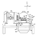
- 1 is a top view of an electrodynamic vibration test apparatus according to an embodiment of the present invention.
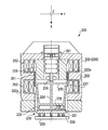
- 1 is a front view of an electrodynamic vibration testing apparatus according to an embodiment of the present invention. It is sectional drawing of the 1st actuator of the electrodynamic type vibration testing apparatus which concerns on embodiment of this invention. It is a top view of the 1st connection part of the electrodynamic vibration testing apparatus concerning an embodiment of the invention. It is the side view which looked at the 1st connection part of the electrodynamic vibration testing device concerning an embodiment of the invention from the Y-axis direction. It is sectional drawing of the rail and runner block which are used for the 1st connection part of the electrodynamic vibration testing apparatus which concerns on embodiment of this invention. It is II sectional drawing of FIG.
- FIG. 10 is a sectional view taken along line II-II in FIG.
- FIG. 10 is a cross-sectional view taken along the line III-III in FIG. 9. It is a perspective view of the roller provided in the runner block of the linear guide mechanism used in the modification of embodiment of this invention.
- 1 is a block diagram of an electrodynamic vibration testing apparatus according to an embodiment of the present invention.
- FIG. 1 and 2 are a top view and a side view, respectively, of the electrodynamic vibration test apparatus of the present embodiment.
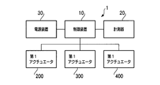
- FIG. 13 is a block diagram of the electrodynamic vibration test apparatus of this embodiment.
- the vibration test apparatus 1 of the present embodiment is configured such that the vibration test apparatus 1 of the present embodiment fixes a subject to be subjected to a vibration test on a table 100, and Using the second and third actuators 200, 300, and 400, the table 100 and the subject on the table 100 are vibrated in three orthogonal directions. As shown in FIG.
- the first, second, and third actuators 200, 300, and 400 are controlled by the control device 10, and the first, second, and third actuators 200, 300, and 400 are controlled.
- the control device 10 controls the magnitude and frequency of an alternating current (described later) input to the movable coil, so that the table 100 can be vibrated with a desired amplitude and frequency.
- the table 100 is provided with a measuring device 20 such as a vibration pickup, and the measuring device 20 can measure the degree of vibration (speed, acceleration, amplitude, etc.) of the table. Further, the control device 10 adjusts the magnitude and frequency of an alternating current (described later) input to the movable coils of the first, second, and third actuators 200, 300, and 400 based on the measurement result of the measuring instrument 20.
- control device 10 can control the actuators 200, 300, and 400 so that a predetermined direction component of the maximum speed of the table 100 has a predetermined magnitude.
- the control device 10, the measuring instrument 20, and the actuators 200, 300, and 400 are configured to be driven by receiving power supplied from the power supply device 30.
- the direction in which the first actuator 200 vibrates the table 100 is the X-axis direction
- the direction in which the second actuator 300 vibrates the table 100 is the horizontal direction in FIG. 1).
- the Y-axis direction, the direction in which the third actuator 400 vibrates the table, that is, the vertical direction (the direction orthogonal to the paper surface in FIG. 1) is defined as the Z-axis direction.
- the first, second, and third actuators 200, 300, and 400 are fixed to the apparatus base 2 via first, second, and third fixing blocks 210, 310, and 410, respectively.
- the first, second, and third fixing blocks 210, 310, and 410 are fixed to the apparatus base 2 by the block fixing bolt B1, and the first and second fixing blocks B2 (FIG. 2) are used.
- the third actuators 200, 300, and 400 are fixed to the first, second, and third fixing blocks 210, 310, and 410, respectively.
- grooves 202 extending in the Z-axis direction are formed at both ends of the first actuator 200 in the Y-axis direction.
- the bottom surface of the groove 202 is formed in a planar shape substantially parallel to the XZ plane.
- the first fixed block 210 is formed with protrusions 212 whose width and height are approximately equal to the width and maximum height of the groove 202, respectively.
- the top surface of the projecting portion 212 (the surface on the tip side of the projecting portion 212 projecting in the Y-axis direction) is also substantially parallel to the XZ plane, and the projecting portion 212 fits in the groove 202 with almost no gap. And the top surface of the protruding portion 212 abut.
- the first actuator 200 When the first actuator 200 is fixed to the first fixing block 210 with the actuator fixing bolt B2 in a state where the protruding portion 212 is fitted in the groove 202, the groove 202 and the protruding portion 212 are engaged. Further, since the top surface of the projecting portion 212 having a large area urges the bottom surface of the groove 202 over almost the whole surface by tightening the bolt B2, the groove 202 and the first fixed block are caused by concentrated load. 210 is not greatly deformed. As a result, the first actuator 200 is firmly fixed.
- the second and third actuators 300 and 400 are also provided with grooves 302 and 402 similar to the groove 202, and the second and third fixing blocks 310 and 410 are provided in the grooves 302 and 402. Corresponding protrusions 312 and 412 are formed, respectively. Accordingly, the second actuators 300 and 400 are also firmly fixed by the engagement between the grooves 302 and 402 and the protruding portions 312 and 412.
- the first, second, and third actuators 200, 300, and 400 are different only in the mounting direction with respect to the table 100, and the configuration for driving the table 100 is the same. Only the explanation is given.
- FIG. 3 is a cross-sectional view of the first actuator 200.
- the first actuator includes a fixed portion 220 having a cylindrical body 222 and a movable portion 230 that is housed in a cylinder of the fixed portion 220 and is slidable in the X axis direction with respect to the fixed portion.
- the movable part 230 includes a movable frame 232 having a tapered cylindrical shape and a top plate 231 fixed to the end of the movable frame 232 on the table 100 side.
- An intermediate table 233 is fixed to the top plate 231 via a plurality of bars 236.
- the movable coil 251 is attached to the end of the movable frame 232 opposite to the top plate 231 via a movable coil holding member 237.
- the movable coil 251 is disposed substantially coaxially with the movable frame 232.
- a cylindrical inner magnetic pole 225 formed coaxially with the cylindrical body 22 is fixed inside the cylindrical body 222 of the fixing portion 220.
- the outer diameter of the inner magnetic pole 225 is smaller than the inner diameter of the movable coil 251, and the movable coil 251 is disposed between the outer peripheral surface of the inner magnetic pole 225 and the inner peripheral surface of the cylindrical body 222.
- a plurality of concave portions 222 a that are concave toward the radially outer side of the cylindrical body 222 are provided on the inner peripheral surface of the cylindrical body 222, and the radius of the cylindrical body 222 is provided inside each of the concave portions 222 a.
- a fixed coil 252 formed by winding a conducting wire around the direction is attached.
- the cylindrical body 222 and the inner magnetic pole 225 are both formed of a ferromagnetic body or a ferrimagnetic body, and when a direct current is passed through the fixed coil 252, the radial direction of the cylindrical body 222, that is, the radius of the movable coil 251. A magnetic field is generated in the direction.
- the intermediate table 233 can be vibrated in the X-axis direction by supplying an alternating current to the movable coil 251 and reciprocating the movable frame 232 in the X-axis direction. it can.
- an air spring 261 is accommodated in the inner magnetic pole 225.
- One end (the upper side in the figure) of the air spring 261 is fixed to the fixing portion 220.
- the air spring 261 and the movable frame 232 are connected via a connecting bar 234 extending vertically upward from the other end (lower side in the figure) of the air spring 261.
- the connecting bar 234 passes through the movable frame 232 and reaches the vicinity of the top plate 231, and the plurality of beams 235 extending in the radial direction of the movable frame 232 are connected to the movable frame 232.
- the inner peripheral surface and the connecting bar 234 are connected.
- a bearing 238 that supports the connecting bar 234 so that the moving direction of the connecting bar 234 is only in the X-axis direction is fixed in the inner space of the inner magnetic pole 225.
- the first, second, and third actuators 200, 300, and 400 and the table 100 include the first, second, and third connecting portions 240, respectively. 340 and 440 are connected. Next, the configuration of the first, second, and third connecting portions 240, 340, and 440 will be described.
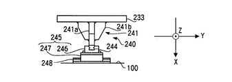
- FIG. 4 is a top view of the first connecting portion 240.
- FIG. 5 is a side view of the first connecting portion 240 viewed from the Y-axis direction.
- the first connecting portion includes a Z-axis rail spacer 241, a Z-axis rail 244, an intermediate stage 245, and a Y-axis rail 248.
- the Z-axis rail spacer 241 includes a plate portion 241a welded to the intermediate table 233 so as to be orthogonal to the intermediate table 233, and a rib 241b welded to a corner formed by the plate portion 241a and the intermediate table 233.
- the plate portion 241a is disposed in parallel with the ZX plane, and is an end portion on the X-axis positive direction side (side from the first actuator 200 toward the table 100, the lower side in FIG. 4, the right side in FIG. 5), that is, the middle.
- a Z-axis rail 244 is fixed to the end opposite to the side fixed to the table 233.
- the Z-axis rail 244 is a rail extending in the Z-axis direction.
- the Y-axis rail 248 is a rail that is fixed to the end surface of the table 100 that faces the intermediate table 233 and extends in the Y-axis direction. 4 is fixed to the end of the upper side of FIG.
- the intermediate stage 245 includes a Z-axis runner block 246 that engages with the Z-axis rail 244 on the X-axis negative direction side, and a Y-axis runner block 247 that engages with the Y-axis rail 248 on the X-axis positive direction side. Is a block.
- the intermediate stage 245 can slide in the Z-axis direction with respect to the Z-axis rail 246 and in the Y-axis direction with respect to the Y-axis rail 248, respectively.
- the intermediate stage 245 can slide in the Y-axis direction with respect to the table 100 and can slide in the Z-axis direction with respect to the first actuator 200. Therefore, the first actuator 200 can slide in the Y-axis direction and the Z-axis direction with respect to the table 100.
- the first actuator 200 is thereby moved in the Y-axis direction and the Z-axis direction. No load is applied, and bending stress due to the displacement of the table 100 in the Y-axis direction and / or the Z-axis direction is not applied to the movable portion 230 (FIG. 3) of the first actuator 200 or the like.
- the second connecting portion 340 has the same structure except that the first connecting portion 240 described above is installed in a different direction (X axis and Y axis are interchanged). Therefore, the description of the second connection part 340 is omitted.
- the third connecting portion 440 includes a pair of Y-axis rails 444, a pair of X-axis rails 448, and a plurality of intermediate stages 445.
- the pair of Y-axis rails 444 are both rails extending in the Y-axis direction, and are arranged and fixed on the upper surface of the intermediate table 433 of the third actuator 400 in the X-axis direction.
- the pair of X-axis rails 448 are rails that extend in the X-axis direction, and are fixed to the lower surface of the table 100 side by side in the Y-axis direction.
- the intermediate stage 445 is a block in which an X-axis runner block 447 that engages with the X-axis rail 448 is provided at the upper portion, and a Y-axis runner block 446 that engages with the Y-axis rail 444 is provided at the lower portion.
- the intermediate stage 445 can slide with respect to both the X-axis rail 448 and the Y-axis rail 444.
- One intermediate stage 445 is provided for each position where the X-axis rail 448 and the Y-axis rail 444 cross each other. Since two X-axis rails 448 and two Y-axis rails 444 are provided, the X-axis rail 448 and the Y-axis rail 444 intersect at four points. Therefore, in this embodiment, four intermediate stages 445 are used.
- each of the intermediate stages 445 is slidable in the X-axis direction with respect to the table 100 and slidable in the Y-axis direction with respect to the third actuator 300. That is, the table 100 is slidable in the X axis direction and the Y axis direction with respect to the third actuator 400. Therefore, even if the table 100 is vibrated in the X-axis direction and / or the Y-axis direction by the first actuator 200 and / or the second actuator 300, the third actuator 400 is thereby caused to move in the X-axis direction and the Y-axis direction. No load is applied, and bending stress resulting from displacement of the table 100 in the X-axis direction and / or Y-axis direction is not applied to the movable portion of the third actuator 400 or the like.
- the third actuator 400 is provided with a pair of X-axis rails 448 and Y-axis rails 444 to support the relatively heavy table 100 and the subject, and the X-axis rails 448 and Y-axis are provided.
- An intermediate stage 445 is disposed at each portion where the rail 444 intersects.
- the load of the subject and the heavy table 100 is applied to the third actuator 400.
- the center of gravity of the table 100 is shifted from the central axis of the movable part of the third actuator 400 due to the vibration in the X-axis and Y-axis directions, and a large moment is applied to the movable part.
- a rail 451 extending in the Z-axis direction and a runner block that can be advanced and retracted along the rail 451 by engaging with the rail 451 so that the movable portion does not fall down due to this moment.
- the movable portion of the third actuator 400 is supported by a linear guide mechanism 450 having 452.
- an L-shaped guide frame 453 is fixed to the upper surface 423 of the fixing portion 420 of the third actuator 400, and the rail 451 extending in the Z-axis direction is
- the guide frame 453 is fixed to one surface of the upright portion 453a (a plate standing vertically from the upper surface 423 of the fixing portion 420).
- the runner block 452 that engages with the rail 451 is fixed to the intermediate table 433 of the third actuator 400.
- Four sets of linear guides 450 are provided on the circumference centering on the central axis of the third actuator at about 90 degrees, and the movable parts of the third actuator 400 are guided from four directions by these four sets. It has become so.
- the table 100 can slide in any direction on a plane perpendicular to the driving direction of the actuator. For this reason, even if the table 100 is displaced by a certain actuator, the load or moment resulting from this displacement is not applied to the other actuator, and the other actuator and the table 100 are engaged via the intermediate stage. Is maintained. That is, even if the table is displaced to an arbitrary position, a state in which each actuator can displace the table is maintained. Therefore, in the present embodiment, the three actuators 200, 300, and 400 can be simultaneously driven to vibrate the table 100 and the subject fixed on the table 100 in three axial directions.
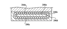
- FIG. 6 is a cross-sectional view of the rail 244 and the runner block 246 of the first connecting portion 240 taken along a plane perpendicular to the major axis direction of the rail 244 (that is, the XY plane), and FIG. 7 is a cross-sectional view taken along II of FIG. It is sectional drawing.
- the runner block 246 is formed with a recess so as to surround the rail 244, and in this recess, four grooves 246 a and 246 a ′ extending in the axial direction of the rail 244 are formed.
- Numerous stainless steel balls 246b are accommodated in the grooves 246a and 246a '.
- the rail 244 is provided with grooves 244a and 244a ′ at positions facing the grooves 246a and 246a ′ of the runner block 246, respectively, and the ball 246b is formed with the grooves 246a and 244a or the grooves 246a ′ and 244a ′. It is designed to be sandwiched between.
- the cross-sectional shape of the grooves 246a, 246a ', 244a, 244a' is an arc shape, and the radius of curvature thereof is substantially equal to the radius of the ball 246b. For this reason, the ball 246b is in close contact with the grooves 246a, 246a ', 244a, 244a' with almost no play.
- each ball retraction paths 246c, 246c ' are provided substantially parallel to the grooves 246a, 246a'.
- the groove 246a and the retreat path 246c are connected to each other via U-shaped paths 246d, and the grooves 246a, 244a, retreat paths 246c, and U-shaped paths 46d
- a circulation path for circulating 246b is formed.
- a similar circulation path is also formed by the groove 246a ', the groove 244a', and the retreat path 246c '.
- the two rows of balls 246b sandwiched between the grooves 246a and 244a form a front combination angular contact ball bearing having a contact angle of approximately ⁇ 45 °.
- the contact angle in this case is the radial direction of the rail 244 and the runner block 246 (the direction from the runner block to the rail), where the grooves 246a and 244a contact the balls 246b. It is an angle made with respect to (upward direction).
- the angular ball bearing formed in this way is in the reverse radial direction (the direction from the rail toward the runner block, the downward direction in FIG. 6) and the lateral direction (the direction orthogonal to both the radial direction and the advance / retreat direction of the runner block). Yes, the load in the left-right direction in FIG. 6 can be supported.
- the two rows of balls 246b sandwiched between the grooves 246a ′ and 244a ′ have a contact angle (the line connecting the contact points where the grooves 246a ′ and 244a ′ are in contact with the ball 246b is the reverse of the linear guide).
- a front combination angular contact ball bearing having an angle of about ⁇ 45 ° with respect to the radial direction is formed. This angular ball bearing can support radial and lateral loads.
- Two rows of balls 246b sandwiched between one of the grooves 246a and 244a (right side in the figure) and one of the grooves 246a ′ and 244a ′ (right side in the figure) are also provided with a front combination type angular ball bearing.
- two rows of balls 246b sandwiched between the other of the grooves 246a and 244a (left side in the figure) and the other of the grooves 246a ′ and 244a ′ (left side in the figure) are also provided with a front combination type angular ball bearing.
- the front combination angular contact ball bearing having a large number of balls 246b supports the loads acting in the radial direction, the reverse radial direction, and the lateral direction, and the rail shaft A large load applied in a direction other than the direction can be sufficiently supported.
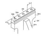
- FIG. 8 is a perspective view showing the rail 244 attached to the Z-axis rail spacer 241.
- the rail mounting structure is the same for other rails used in the vibration testing apparatus of this embodiment.
- the rail 244 is formed with a plurality of through holes 244b arranged in the axial direction. Although not shown in the drawing, a plurality of bolt holes are formed at positions corresponding to the through holes 244b of the plate portion 241a of the Z-axis rail spacer 241.
- the rail 244 is fixed to the Z-axis rail spacer 241 by screwing the bolt 244c through the through-hole 244b into the bolt hole of the plate portion 241a.
- the interval between the through-holes 244b of the rail 244 (and the interval between the bolt holes of Anzaka) s is relatively short, 50 to 80%, preferably 60 to 70% of the width w of the rail 244. Yes.
- the rail 244 is firmly fixed to the Z-axis rail spacer 241 without bending.
- the runner block 246 is slid with respect to the rail 244 by rolling of the ball 246b.
- the embodiment of the present invention is not limited to the above configuration. Absent.
- a roller 1246b may be used instead of the ball 246b, and a linear guide mechanism that slides the runner block 1246 relative to the rail 1244 by rolling of the roller 1246b may be used.
- FIG. 9 to 12 show a linear guide mechanism used in a modification of the present embodiment. Except for the linear guide mechanism described below, the configuration of this modification is the same as that of the above embodiment.
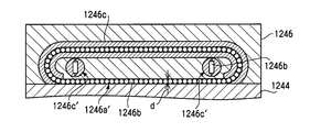
- FIG. 9 is a cross-sectional view of the runner block 1246 and the rail 1244 cut along a plane perpendicular to the major axis direction of the rail 1244.
- 10 and 11 are a II-II sectional view and a III-III sectional view of FIG. 9, respectively.
- the runner block 1246 is formed with a recess 1246 e so as to surround the rail 1244.
- a roller holding member 1246f is sandwiched between the recess 1246e and the outer peripheral surface of the rail 1244.
- roller holding member 1246f By this roller holding member 1246f, four rolling grooves 1246a and 1246a 'extending in the axial direction are formed in the gap between the recess 1246e and the outer peripheral surface of the rail 1244. A number of stainless steel rollers 1246b are accommodated in the rolling grooves 1246a and 1246a '. Both ends of the roller 1246b in the axial direction are held by a roller holding member 1246f, and the cylindrical surface is in contact with both the recess of the runner block 1246 and the outer peripheral surface of the rail 1244.
- the distance between the recess of the runner block 1246 and the outer peripheral surface of the rail 1244 is substantially equal to the diameter of the roller 1246b, and the roller 1246b is in close contact with the recess 1246e of the runner block 1246 and the outer peripheral surface of the rail 1244 with little play.
- two rail retreat paths 1246c ' are provided that are substantially parallel to the rolling grooves 1246a.
- the rail retracting path 246c ' is formed by bending a tube that accommodates the roller 1246b into a C-shape.
- the rolling groove 1246a and the retreat path 1246c ' are connected at both ends, and form a circulation path for circulating the roller 1246b.
- two rail retractions 1246 c that are substantially parallel to the rolling grooves 1246 a ′ are provided inside the runner block 1246, and the retreating path 1246 c and the rolling grooves 1246 a ′ are also provided.
- a similar circulation path is formed.
- the distance d (FIGS. 10 and 11) between the recess 1246e of the runner block 1246 and the outer peripheral surface of the rail 1244 is a length that is slightly larger (1 micrometer or less) than the diameter of the roller 1246b. ing. In such a state, the preload from the roller 1246b is applied to the runner block 1246 and the rail 1244, and the outer peripheral surface of the roller 1246b is in close contact with the concave portion 1246e of the runner block 1246 and the outer peripheral surface of the rail 1244.
- the four rows of rollers 1246b arranged in the four rolling grooves 1246a and 1246a ′ have their axes every 90 ° on a plane orthogonal to the axis of the rail 1244. It is arranged as follows.
- each roller 1246b is arranged in this way, when a load in a direction from the runner block 1246 toward the upper surface of the rail 1244 (a direction from bottom to top in FIG. 9) is applied, this load mainly includes two rolling elements. Two rows of rollers 1246b disposed in the moving groove 1246a receive the movement. In addition, when a load in a direction away from the upper surface of the rail 1244 is applied to the runner block 1246 (the direction from the top to the bottom in FIG. 9), this load is mainly disposed in the two rolling grooves 1246a ′. Two rows of rollers 1246b receive.
- the load when a load is applied to the runner block 1246 in a direction from one side surface (left side in the figure) to the other side surface (right side in the figure), the load is mainly the runner blocks of the rolling grooves 1246a ′ and 1246a. Two rows of rollers 1246b arranged on one side (left side in the figure) receive.
- the load when a load is applied to the runner block 1246 in the direction from the other side to the one side, the load is mainly disposed on the other side of the runner block (right side in the drawing) of the rolling grooves 1246a ′ and 1246a. The two rows of rollers 1246b are received.
- the linear guide mechanism of this embodiment does not cause damage to the roller 1246b by applying a load only to the roller 1246b in a specific row even if a large load is applied in these directions, and smoothly rolls.
- the runner block 1246 can be smoothly moved along the rail 1244 by the roller 1246b.
- FIG. 12 A perspective view of the roller 1246b of the runner block 1246 is shown in FIG.
- a retainer 1246g is provided between the rollers of the runner block used in the vibration test apparatus 1 of the present embodiment.
- the retainer 1246g has two cylindrical surfaces that are in contact with the outer peripheral surfaces of the two adjacent rollers 1246b, and the retainer 246g contacts the roller 1246b through the cylindrical surfaces.
- the axes of the two cylindrical surfaces of the retainer 1246g are parallel to each other. Since the retainer 1246g is in contact with the roller 1246b before and after the retainer 1246g, the rollers 1246b in the circulation path are aligned so that their axial directions are parallel to each other. For this reason, the roller 1246b circulates smoothly in the circulation path without rattling.
- the rollers 1246b are in contact with each other with a relatively small contact area, so that a large stress is applied to the contact portion.
- the cylindrical surfaces of the roller 1246b and the retainer 1246g are in contact with each other with a relatively wide contact area, and the stress applied to the roller 1246b by this contact is kept relatively small. Therefore, the linear guide mechanism of this embodiment can suppress the damage and wear of the roller 1246b, compared to the linear guide mechanism that does not have a retainer.
- the linear guide mechanism of the present embodiment is configured such that the rollers 1246b do not directly contact each other.
- the rollers 1246b are in direct contact with each other, noise is generated.
- the retainer 1246g is disposed between the rollers 1246b, such noise can be suppressed.
Landscapes
- Physics & Mathematics (AREA)
- General Physics & Mathematics (AREA)
- Bearings For Parts Moving Linearly (AREA)
Abstract
L'invention porte sur un équipement de test par vibrations électrodynamiques qui comprend : des premier et second actionneurs électrodynamiques qui peuvent faire vibrer une table dans des première et seconde directions orthogonales entre elles ; des premiers moyens de couplage pour permettre à la table de coulisser dans la seconde direction par rapport au premier actionneur électrodynamique ; et de seconds moyens de couplage pour permettre à la table de coulisser dans la première direction par rapport au second actionneur électrodynamique. Chaque actionneur peut coulisser par rapport à la table dans la direction orthogonale à la direction de vibration de l'actionneur, de telle sorte que même lorsque la table est amenée à vibrer par l'un des actionneurs, étant donné que la table coulisse par rapport à l'autre actionneur, l'autre actionneur n'est pas déplacé et la direction de vibration de l'autre actionneur n'est pas changée. Ainsi, une diaphonie ne se produit pas, de telle sorte que l'équipement de test de vibration électrodynamique fait vibrer une table dans des directions à deux axes orthogonales ou des directions à trois axes orthogonales.
Priority Applications (1)
| Application Number | Priority Date | Filing Date | Title |
|---|---|---|---|
| TW098113448A TW200944774A (en) | 2008-04-25 | 2009-04-23 | Electrodynamic vibration test equipment |
Applications Claiming Priority (2)
| Application Number | Priority Date | Filing Date | Title |
|---|---|---|---|
| JP2008116436 | 2008-04-25 | ||
| JP2008-116436 | 2008-04-25 |
Publications (1)
| Publication Number | Publication Date |
|---|---|
| WO2009130953A1 true WO2009130953A1 (fr) | 2009-10-29 |
Family
ID=41216694
Family Applications (1)
| Application Number | Title | Priority Date | Filing Date |
|---|---|---|---|
| PCT/JP2009/054616 Ceased WO2009130953A1 (fr) | 2008-04-25 | 2009-03-11 | Equipement de test par vibrations électrodynamiques |
Country Status (2)
| Country | Link |
|---|---|
| TW (1) | TW200944774A (fr) |
| WO (1) | WO2009130953A1 (fr) |
Cited By (10)
| Publication number | Priority date | Publication date | Assignee | Title |
|---|---|---|---|---|
| JPH0487386A (ja) * | 1990-07-31 | 1992-03-19 | Toshiba Corp | パルス色素レーザシステム |
| WO2012147607A1 (fr) | 2011-04-26 | 2012-11-01 | 国際計測器株式会社 | Actionneur électrodynamique et dispositif d'excitation électrodynamique |
| CN104406608A (zh) * | 2014-11-28 | 2015-03-11 | 陕西宝成航空仪表有限责任公司 | 陀螺静平衡用振动台 |
| CN105115521A (zh) * | 2015-08-31 | 2015-12-02 | 芜湖宏景电子股份有限公司 | 汽车导航模组振动测试装置 |
| WO2016017744A1 (fr) * | 2014-07-30 | 2016-02-04 | 国際計測器株式会社 | Dispositif d'application de vibrations, actionneur électrodynamique, dispositif de guidage croisé, dispositif de guidage linéaire, et table vibrante |
| JP2016035471A (ja) * | 2011-04-26 | 2016-03-17 | 国際計測器株式会社 | 動電型アクチュエータ及び動電型加振装置 |
| CN106289696A (zh) * | 2016-10-10 | 2017-01-04 | 镇江高等职业技术学校 | 基于并联机构的三平移振动台 |
| JP2018009982A (ja) * | 2016-06-30 | 2018-01-18 | 国際計測器株式会社 | 加振装置 |
| CN115406610A (zh) * | 2022-09-01 | 2022-11-29 | 中国矿业大学 | 一种电动振动台三轴向自动倒台装置 |
| US11898944B2 (en) | 2016-01-15 | 2024-02-13 | Kokusai Keisokuki Kabushiki Kaisha | Oscillation device with a vibrating table that houses an oscillated object |
Families Citing this family (1)
| Publication number | Priority date | Publication date | Assignee | Title |
|---|---|---|---|---|
| TWI480122B (zh) * | 2012-07-13 | 2015-04-11 | Univ Nat Kaohsiung Applied Sci | 工具機振動載台 |
Citations (3)
| Publication number | Priority date | Publication date | Assignee | Title |
|---|---|---|---|---|
| JPH03277810A (ja) * | 1990-03-23 | 1991-12-09 | Nippon Seiko Kk | 耐衝撃性リニアガイド装置 |
| JP2001108570A (ja) * | 1999-10-07 | 2001-04-20 | Sanesu:Kk | 3軸方向振動試験装置 |
| JP2006234032A (ja) * | 2005-02-23 | 2006-09-07 | Nsk Ltd | 直動案内軸受装置 |
-
2009
- 2009-03-11 WO PCT/JP2009/054616 patent/WO2009130953A1/fr not_active Ceased
- 2009-04-23 TW TW098113448A patent/TW200944774A/zh unknown
Patent Citations (3)
| Publication number | Priority date | Publication date | Assignee | Title |
|---|---|---|---|---|
| JPH03277810A (ja) * | 1990-03-23 | 1991-12-09 | Nippon Seiko Kk | 耐衝撃性リニアガイド装置 |
| JP2001108570A (ja) * | 1999-10-07 | 2001-04-20 | Sanesu:Kk | 3軸方向振動試験装置 |
| JP2006234032A (ja) * | 2005-02-23 | 2006-09-07 | Nsk Ltd | 直動案内軸受装置 |
Cited By (47)
| Publication number | Priority date | Publication date | Assignee | Title |
|---|---|---|---|---|
| JPH0487386A (ja) * | 1990-07-31 | 1992-03-19 | Toshiba Corp | パルス色素レーザシステム |
| US11289991B2 (en) | 2011-04-26 | 2022-03-29 | Kokusai Keisokuki Kabushiki Kaisha | Electrodynamic actuator and electrodynamic excitation device with movable part support mechanism and fixed part support mechanism |
| JP2012237736A (ja) * | 2011-04-26 | 2012-12-06 | Kokusai Keisokki Kk | 動電型アクチュエータ及び動電型加振装置 |
| US20140049122A1 (en) * | 2011-04-26 | 2014-02-20 | Kokusai Keisokuki Kabushiki Kaisha | Electrodynamic actuator and electrodynamic excitation device |
| KR20140028024A (ko) | 2011-04-26 | 2014-03-07 | 고쿠사이 게이소쿠키 가부시키가이샤 | 동전형 액추에이터 및 동전형 가진 장치 |
| US20240055968A1 (en) * | 2011-04-26 | 2024-02-15 | Kokusai Keisokuki Kabushiki Kaisha | Electrodynamic Actuator and Electrodynamic Excitation Device |
| US11824416B2 (en) | 2011-04-26 | 2023-11-21 | Kokusai Keisokuki Kabushiki Kaisha | Electrodynamic actuator and electrodynamic excitation device |
| EP4191846A1 (fr) | 2011-04-26 | 2023-06-07 | Kokusai Keisokuki Kabushiki Kaisha | Actionneur électrodynamique et dispositif d'excitation électrodynamique |
| EP2713487A4 (fr) * | 2011-04-26 | 2016-03-16 | Kokusai Keisokuki Kk | Actionneur électrodynamique et dispositif d'excitation électrodynamique |
| JP2016035471A (ja) * | 2011-04-26 | 2016-03-17 | 国際計測器株式会社 | 動電型アクチュエータ及び動電型加振装置 |
| KR102181674B1 (ko) * | 2011-04-26 | 2020-11-23 | 고쿠사이 게이소쿠키 가부시키가이샤 | 동전형 액추에이터 및 동전형 가진 장치 |
| CN103609009B (zh) * | 2011-04-26 | 2017-03-29 | 国际计测器株式会社 | 电动致动器和电动激振装置 |
| WO2012147607A1 (fr) | 2011-04-26 | 2012-11-01 | 国際計測器株式会社 | Actionneur électrodynamique et dispositif d'excitation électrodynamique |
| KR102266234B1 (ko) | 2011-04-26 | 2021-06-17 | 고쿠사이 게이소쿠키 가부시키가이샤 | 동전형 액추에이터 및 가진 장치 |
| KR20200135546A (ko) | 2011-04-26 | 2020-12-02 | 고쿠사이 게이소쿠키 가부시키가이샤 | 동전형 액추에이터 및 가진 장치 |
| EP3624316A1 (fr) | 2011-04-26 | 2020-03-18 | Kokusai Keisokuki Kabushiki Kaisha | Actionneur électrodynamique et dispositif d'excitation électrodynamique |
| EP3176562A4 (fr) * | 2014-07-30 | 2018-05-23 | Kokusai Keisokuki Kabushiki Kaisha | Dispositif d'application de vibrations, actionneur électrodynamique, dispositif de guidage croisé, dispositif de guidage linéaire, et table vibrante |
| KR102498200B1 (ko) * | 2014-07-30 | 2023-02-09 | 고쿠사이 게이소쿠키 가부시키가이샤 | 가진 장치 |
| JP2018185341A (ja) * | 2014-07-30 | 2018-11-22 | 国際計測器株式会社 | 加振装置、アクチュエータ及びアクチュエータの固定部支持機構 |
| JP2018205322A (ja) * | 2014-07-30 | 2018-12-27 | 国際計測器株式会社 | 加振装置 |
| US10281356B2 (en) | 2014-07-30 | 2019-05-07 | Kokusai Keisokuki Kabushiki Kaisha | Oscillating device, electrodynamic actuator, cross guideway, linear guideway and vibrating table |
| US10436670B2 (en) | 2014-07-30 | 2019-10-08 | Kokusai Keisokuki Kabushiki Kaisha | Oscillating device, electrodynamic actuator, cross guideway, linear guideway and vibrating table |
| CN110530591A (zh) * | 2014-07-30 | 2019-12-03 | 国际计测器株式会社 | 电动型致动器、激振装置、致动器及其固定部支承机构 |
| KR20200071779A (ko) * | 2014-07-30 | 2020-06-19 | 고쿠사이 게이소쿠키 가부시키가이샤 | 가진 장치 |
| KR102595796B1 (ko) * | 2014-07-30 | 2023-10-30 | 고쿠사이 게이소쿠키 가부시키가이샤 | 가진 장치 |
| KR20230022306A (ko) * | 2014-07-30 | 2023-02-14 | 고쿠사이 게이소쿠키 가부시키가이샤 | 가진 장치 |
| WO2016017744A1 (fr) * | 2014-07-30 | 2016-02-04 | 国際計測器株式会社 | Dispositif d'application de vibrations, actionneur électrodynamique, dispositif de guidage croisé, dispositif de guidage linéaire, et table vibrante |
| EP3760998A1 (fr) * | 2014-07-30 | 2021-01-06 | Kokusai Keisokuki Kabushiki Kaisha | Dispositif oscillant pour coupler une table vibrante à une unité oscillante sur l'axe z |
| JPWO2016017744A1 (ja) * | 2014-07-30 | 2017-06-22 | 国際計測器株式会社 | 加振装置、動電型アクチュエータ、クロスガイドウェイ、リニアガイドウェイ及び振動テーブル |
| CN110530591B (zh) * | 2014-07-30 | 2021-12-10 | 国际计测器株式会社 | 电动型致动器、激振装置、致动器及其固定部支承机构 |
| KR102350411B1 (ko) * | 2014-07-30 | 2022-01-14 | 고쿠사이 게이소쿠키 가부시키가이샤 | 가진 장치 |
| KR20220011778A (ko) * | 2014-07-30 | 2022-01-28 | 고쿠사이 게이소쿠키 가부시키가이샤 | 가진 장치 |
| KR102357171B1 (ko) | 2014-07-30 | 2022-02-08 | 고쿠사이 게이소쿠키 가부시키가이샤 | 가진 장치 |
| KR20170036050A (ko) * | 2014-07-30 | 2017-03-31 | 고쿠사이 게이소쿠키 가부시키가이샤 | 가진 장치, 동전형 액추에이터, 크로스 가이드웨이, 리니어 가이드웨이 및 진동 테이블 |
| EP4036548A1 (fr) * | 2014-07-30 | 2022-08-03 | Kokusai Keisokuki Kabushiki Kaisha | Dispositif oscillant pour coupler une table vibrante à une unité oscillante sur l'axe z |
| JP2018185340A (ja) * | 2014-07-30 | 2018-11-22 | 国際計測器株式会社 | 加振装置及び動電型アクチュエータ |
| CN104406608B (zh) * | 2014-11-28 | 2017-10-20 | 陕西宝成航空仪表有限责任公司 | 陀螺静平衡用振动台 |
| CN104406608A (zh) * | 2014-11-28 | 2015-03-11 | 陕西宝成航空仪表有限责任公司 | 陀螺静平衡用振动台 |
| CN105115521A (zh) * | 2015-08-31 | 2015-12-02 | 芜湖宏景电子股份有限公司 | 汽车导航模组振动测试装置 |
| US11898944B2 (en) | 2016-01-15 | 2024-02-13 | Kokusai Keisokuki Kabushiki Kaisha | Oscillation device with a vibrating table that houses an oscillated object |
| US12442715B2 (en) | 2016-01-15 | 2025-10-14 | Kokusai Keisokuki Kabushiki Kaisha | Oscillation device with counter balancer |
| JP2022163199A (ja) * | 2016-06-30 | 2022-10-25 | 国際計測器株式会社 | 加振装置 |
| JP7130221B2 (ja) | 2016-06-30 | 2022-09-05 | 国際計測器株式会社 | 加振装置 |
| JP7333981B2 (ja) | 2016-06-30 | 2023-08-28 | 国際計測器株式会社 | 加振装置 |
| JP2018009982A (ja) * | 2016-06-30 | 2018-01-18 | 国際計測器株式会社 | 加振装置 |
| CN106289696A (zh) * | 2016-10-10 | 2017-01-04 | 镇江高等职业技术学校 | 基于并联机构的三平移振动台 |
| CN115406610A (zh) * | 2022-09-01 | 2022-11-29 | 中国矿业大学 | 一种电动振动台三轴向自动倒台装置 |
Also Published As
| Publication number | Publication date |
|---|---|
| TW200944774A (en) | 2009-11-01 |
Similar Documents
| Publication | Publication Date | Title |
|---|---|---|
| WO2009130953A1 (fr) | Equipement de test par vibrations électrodynamiques | |
| JP5913910B2 (ja) | 直動アクチュエータ及び加振装置 | |
| JP4818436B2 (ja) | 加振試験装置 | |
| US20140150526A1 (en) | Electrodynamic Modal Test Impactor System and Method | |
| JP6971831B2 (ja) | 振動試験機 | |
| JPWO2009130818A1 (ja) | 動電型振動試験装置 | |
| JP2019035705A (ja) | 衝撃試験装置 | |
| US10753438B2 (en) | Lifting drive device and measuring machine using the same | |
| JP2006269509A (ja) | 位置決め装置 | |
| JP2020020817A (ja) | 衝撃試験装置 | |
| US11846609B2 (en) | Electric actuator | |
| JP4717466B2 (ja) | 移送装置{transferapparatus} | |
| KR102009333B1 (ko) | 스테이지장치 | |
| JP2021135249A (ja) | 振動試験装置 | |
| JP2007295702A (ja) | リニアモータ、および、ステージ駆動装置 | |
| JP6416971B2 (ja) | 動電型アクチュエータ及び動電型加振装置 | |
| JP2011258805A (ja) | ヘッド位置決め装置及び部品実装装置 | |
| JPH11281554A (ja) | 材料試験機 | |
| JP2016200434A (ja) | 疲労試験装置および疲労強度評価システム | |
| JPH1010025A (ja) | 2軸型材料試験機 | |
| KR20040012296A (ko) | 이중 h구조를 이용한 장행정 6축 운동 스테이지 | |
| JP7277868B2 (ja) | リニアアクチュエータおよびxyテーブル | |
| JP2006283892A (ja) | テーブル装置 | |
| JP2006281426A (ja) | 位置決め装置 | |
| JP2023158705A (ja) | サスペンション要素部品評価装置 |
Legal Events
| Date | Code | Title | Description |
|---|---|---|---|
| 121 | Ep: the epo has been informed by wipo that ep was designated in this application |
Ref document number: 09735358 Country of ref document: EP Kind code of ref document: A1 |
|
| NENP | Non-entry into the national phase |
Ref country code: DE |
|
| 122 | Ep: pct application non-entry in european phase |
Ref document number: 09735358 Country of ref document: EP Kind code of ref document: A1 |
|
| NENP | Non-entry into the national phase |
Ref country code: JP |