WO2012147607A1 - Actionneur électrodynamique et dispositif d'excitation électrodynamique - Google Patents
Actionneur électrodynamique et dispositif d'excitation électrodynamique Download PDFInfo
- Publication number
- WO2012147607A1 WO2012147607A1 PCT/JP2012/060581 JP2012060581W WO2012147607A1 WO 2012147607 A1 WO2012147607 A1 WO 2012147607A1 JP 2012060581 W JP2012060581 W JP 2012060581W WO 2012147607 A1 WO2012147607 A1 WO 2012147607A1
- Authority
- WO
- WIPO (PCT)
- Prior art keywords
- axis
- actuator
- electrodynamic
- movable
- fixed
- Prior art date
- Legal status (The legal status is an assumption and is not a legal conclusion. Google has not performed a legal analysis and makes no representation as to the accuracy of the status listed.)
- Ceased
Links
Images






Classifications
-
- H—ELECTRICITY
- H02—GENERATION; CONVERSION OR DISTRIBUTION OF ELECTRIC POWER
- H02K—DYNAMO-ELECTRIC MACHINES
- H02K41/00—Propulsion systems in which a rigid body is moved along a path due to dynamo-electric interaction between the body and a magnetic field travelling along the path
- H02K41/02—Linear motors; Sectional motors
-
- B—PERFORMING OPERATIONS; TRANSPORTING
- B06—GENERATING OR TRANSMITTING MECHANICAL VIBRATIONS IN GENERAL
- B06B—METHODS OR APPARATUS FOR GENERATING OR TRANSMITTING MECHANICAL VIBRATIONS OF INFRASONIC, SONIC, OR ULTRASONIC FREQUENCY, e.g. FOR PERFORMING MECHANICAL WORK IN GENERAL
- B06B1/00—Methods or apparatus for generating mechanical vibrations of infrasonic, sonic, or ultrasonic frequency
- B06B1/02—Methods or apparatus for generating mechanical vibrations of infrasonic, sonic, or ultrasonic frequency making use of electrical energy
- B06B1/04—Methods or apparatus for generating mechanical vibrations of infrasonic, sonic, or ultrasonic frequency making use of electrical energy operating with electromagnetism
- B06B1/045—Methods or apparatus for generating mechanical vibrations of infrasonic, sonic, or ultrasonic frequency making use of electrical energy operating with electromagnetism using vibrating magnet, armature or coil system
-
- G—PHYSICS
- G01—MEASURING; TESTING
- G01M—TESTING STATIC OR DYNAMIC BALANCE OF MACHINES OR STRUCTURES; TESTING OF STRUCTURES OR APPARATUS, NOT OTHERWISE PROVIDED FOR
- G01M7/00—Vibration-testing of structures; Shock-testing of structures
- G01M7/02—Vibration-testing by means of a shake table
- G01M7/027—Specimen mounting arrangements, e.g. table head adapters
-
- G—PHYSICS
- G01—MEASURING; TESTING
- G01M—TESTING STATIC OR DYNAMIC BALANCE OF MACHINES OR STRUCTURES; TESTING OF STRUCTURES OR APPARATUS, NOT OTHERWISE PROVIDED FOR
- G01M7/00—Vibration-testing of structures; Shock-testing of structures
- G01M7/02—Vibration-testing by means of a shake table
- G01M7/06—Multidirectional test stands
-
- H—ELECTRICITY
- H02—GENERATION; CONVERSION OR DISTRIBUTION OF ELECTRIC POWER
- H02K—DYNAMO-ELECTRIC MACHINES
- H02K33/00—Motors with reciprocating, oscillating or vibrating magnet, armature or coil system
- H02K33/12—Motors with reciprocating, oscillating or vibrating magnet, armature or coil system with armatures moving in alternate directions by alternate energisation of two coil systems
-
- H—ELECTRICITY
- H02—GENERATION; CONVERSION OR DISTRIBUTION OF ELECTRIC POWER
- H02K—DYNAMO-ELECTRIC MACHINES
- H02K7/00—Arrangements for handling mechanical energy structurally associated with dynamo-electric machines, e.g. structural association with mechanical driving motors or auxiliary dynamo-electric machines
- H02K7/06—Means for converting reciprocating motion into rotary motion or vice versa
-
- H—ELECTRICITY
- H02—GENERATION; CONVERSION OR DISTRIBUTION OF ELECTRIC POWER
- H02K—DYNAMO-ELECTRIC MACHINES
- H02K7/00—Arrangements for handling mechanical energy structurally associated with dynamo-electric machines, e.g. structural association with mechanical driving motors or auxiliary dynamo-electric machines
- H02K7/10—Structural association with clutches, brakes, gears, pulleys or mechanical starters
Definitions
- the present invention relates to an electrodynamic actuator and an electrodynamic excitation device using the same.
- Patent Document 1 discloses a three-axis vibration apparatus 1 in which three electrodynamic actuators 200, 300, and 400 with drive shafts oriented in directions orthogonal to each other are connected to a vibration table 100.
- the drive shaft of each electrodynamic actuator vibrates via a biaxial slider (connecting portions 240, 340, and 440) that can smoothly slide in a biaxial direction perpendicular to the drive shaft. It is connected to the table 100.
- the two-axis slider 240 (340, 440) is formed by connecting a pair of linear guides arranged so that movable axes are orthogonal to each other via an intermediate stage 245 (345, 445). With this configuration, each electrodynamic actuator can drive the vibration table 100 without being strongly influenced by driving of the vibration table 100 by other electrodynamic actuators (that is, with relatively little crosstalk).
- the movable portion 230 is attached to the fixed portion 222 only in the vicinity of the end of the elongated bar 234 protruding in the driving direction from one end of the body portion 232. Since it is supported, the body part 232 of the movable part 230 is not supported with high rigidity in a direction (non-driving direction) orthogonal to the driving shaft, and easily vibrates in the non-driving direction. For this reason, the vibration in the non-driving direction of the movable part 230 may cause crosstalk between the drive shafts, which may reduce the excitation accuracy.
- An object of the present invention is to provide an electrodynamic actuator in which a movable part is unlikely to vibrate in a non-driving direction, and an electrodynamic excitation device having excellent excitation accuracy by using the electrodynamic actuator.
- An electrodynamic actuator includes a substantially cylindrical fixed portion, a movable portion at least partially housed in a hollow portion of the fixed portion, and reciprocally driven in the axial direction of the fixed portion, and a movable portion And a plurality of movable part support mechanisms that support the side part so as to be reciprocally movable in the axial direction of the fixed part.
- the movable part support mechanism includes a rail extending in the axial direction of the fixed part attached to the side surface of the movable part, and a runner block that is attached to the fixed part and engages with the rail, and is centered on the axis of the fixed part Are arranged at substantially equal intervals in the circumferential direction.
- This configuration makes it difficult for the movable portion to vibrate in the non-driving direction because movement of the movable portion in the non-driving direction is restricted by the plurality of movable portion support mechanisms.
- the movable part may be configured to be sandwiched from both sides in two orthogonal directions by two pairs of movable part support mechanisms.
- the electrodynamic actuator may be placed horizontally so that the axis of the fixed part faces the horizontal direction, and one of the movable part support mechanisms may be arranged below the axis of the fixed part.
- the movable portion may include a rod that protrudes from one end thereof and extends on the axis of the fixed portion, and the fixed portion may include a bearing that supports the rod movably in the axial direction of the fixed portion.
- a base and a fixed part support mechanism for supporting the fixed part are provided, and the fixed part support mechanism is slidable in the axial direction of the fixed part, the movable block attached to the fixed part of the electrodynamic actuator, and the movable block and the base.
- the buffer means which is arrange
- the buffer means is, for example, an air spring.
- the fixed part When driving an electrodynamic actuator, the fixed part vibrates strongly in the axial direction due to the reaction force. According to this configuration, since the fixing portion is fixed to the base via the buffering means of the fixing portion support mechanism, transmission of strong axial vibration of the fixing portion to the base is prevented. If such an electrodynamic actuator is used in a multi-axis shaker, crosstalk between excitation axes and unnecessary vibration noise are reduced, and an accurate excitation test can be performed.
- a pair of movable blocks may be provided, and the pair of movable blocks may be attached to both side surfaces sandwiching the axis of the fixed portion.
- the electrodynamic excitation device may include the above electrodynamic actuator and a vibration table coupled to the tip of the movable portion of the electrodynamic actuator.
- an electrodynamic excitation device capable of high-accuracy excitation is provided by using the electrodynamic actuator that causes less vibration in the non-driving direction that causes noise.
- One of the electrodynamic actuators is a first actuator having a drive shaft in the first direction, and the other electrodynamic actuator is orthogonal to the first direction.
- a second actuator having a drive shaft in a second direction, a first slider that slidably connects the vibration table and the first actuator in a second direction, and the vibration table and the second actuator. It is good also as a structure provided with the 2nd slider slidably connected to a 1st direction.
- the two electrodynamic actuators can independently drive the vibration table without interfering with each other, so that a biaxial electrodynamic excitation device capable of accurate excitation is realized.
- a third actuator having a drive shaft in a third direction orthogonal to the first direction and the second direction, a vibration table, and a third actuator are connected to the first actuator.
- a third slider that is slidably coupled in the second direction and the second direction, and the first slider can slide the vibration table and the first actuator in the second direction and the third direction.
- the second slider may be connected so that the vibration table and the second actuator are slidably connected in the first direction and the third direction.
- the three electrodynamic actuators can independently drive the vibration table without interfering with each other, so that a three-axis electrodynamic excitation device capable of accurate excitation is realized.
- an electrodynamic actuator in which the movable portion is unlikely to vibrate in the non-driving direction, and an electrodynamic exciter having excellent excitation accuracy by using the electrodynamic actuator. Provided.
- 1 is a front view of an electrodynamic excitation device according to a first embodiment of the present invention.
- 1 is a plan view of an electrodynamic excitation device according to a first embodiment of the present invention. It is a block diagram of the drive system of the electrodynamic excitation device according to the first embodiment of the present invention.
- It is a front view of the main body of the Z-axis actuator which concerns on 1st Embodiment of this invention.
- It is a top view of the main body of the Z-axis actuator which concerns on 1st Embodiment of this invention.
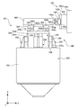
- It is a longitudinal cross-sectional view of the main body of the Z-axis actuator which concerns on 1st Embodiment of this invention.
- FIGS. 1 to 9 an electrodynamic three-axis vibration device 1 (hereinafter abbreviated as “vibration device 1”) according to a first embodiment of the present invention will be described.
- 1 and 2 are a front view and a plan view of the vibration device 1, respectively.
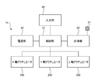
- FIG. 3 is a block diagram showing a schematic configuration of the drive system of the vibration exciter 1.
- the horizontal direction in FIG. 1 is the X-axis direction (the right direction is the X-axis positive direction), and the direction perpendicular to the paper surface is the Y-axis direction (the direction from the front side to the back side is the Y-axis positive direction).
- the vertical direction is the Z-axis direction (the upward direction is the positive Z-axis direction).
- the Z-axis direction is a vertical direction, and the X-axis and Y-axis directions are horizontal directions.
- the vibration device 1 includes a vibration table 400 to which a specimen (not shown) is attached, and three vibration units that vibrate the vibration table 400 in the X-axis, Y-axis, and Z-axis directions, respectively.
- An actuator X-axis actuator 100, Y-axis actuator 200, and Z-axis actuator 300
- the actuators 100, 200, and 300 are electrodynamic linear actuators each having a voice coil motor, and covers 103, 203 that cover the main bodies 101, 201, and 301 and movable portions (described later) protruding from the main bodies. And 303 respectively.
- the vibration table 400 is connected to the actuators 100, 200, and 300 via biaxial sliders (YZ slider 160, ZX slider 260, and XY slider 360), respectively.
- the vibration device 1 can vibrate the specimen attached on the vibration table 400 in three orthogonal directions by driving the vibration table 400 using the actuators 100, 200, and 300.
- the apparatus base 50 is formed by connecting a horizontal bottom plate 54 and a top plate 56 by a plurality of wall plates 58 arranged vertically.
- the actuators 100, 200 and 300 are fixed on the top plate 56 of the apparatus base 50 by a pair of fixing blocks 110, 210 and 310, respectively.
- an opening 57 is formed in the top plate 56, and the lower part of the Z-axis actuator 300 is accommodated in the apparatus base 50 through the opening 57. With this configuration, a reduction in the height of the vibration exciter 1 is realized.
- a plurality of vibration-proof mounts 52 are attached to the lower surface of the bottom plate 54.
- the drive system of the vibration exciter 1 includes a control unit 10 that controls the operation of the entire apparatus, a measurement unit 20 that measures vibration of the vibration table 400, and a power supply unit 30 that supplies power to the control unit 10. And an input unit 40 for receiving user input or data input from an external device.
- the measurement unit 20 includes a three-axis vibration pickup 21 attached to the vibration table 400, amplifies a signal (for example, a speed signal) output from the three-axis vibration pickup 21 and converts it into a digital signal, and then the control unit Send to 10.
- the triaxial vibration pickup 21 detects vibrations in the X-axis, Y-axis, and Z-axis directions of the vibration table 400 independently.
- the control unit 10 determines the magnitude and frequency of the alternating current input to the drive coils (described later) of the actuators 100, 200, and 300. By controlling, the vibration table 400 can be vibrated with a desired amplitude and frequency. Further, the measurement unit 20 calculates various parameters (speed, acceleration, amplitude, power spectral density, etc.) indicating the vibration state of the vibration table 400 based on the signal from the three-axis vibration pickup 21 and sends the calculated parameters to the control unit 10. .
- each actuator 100, 200 and 300 will be described.
- the X-axis actuator 100 and the Y-axis actuator 200 have the same configuration as the Z-axis actuator 300 except that an air spring 330 described later is not provided. A detailed configuration will be described.
- the main body 301 includes a fixed part 320 having a cylindrical body 322 and a movable part 350 accommodated in the cylinder of the fixed part 320.
- the movable part 350 is movable in the Z-axis direction (vertical direction in FIGS. 4 and 6) with respect to the fixed part 320.
- the movable part 350 includes a substantially columnar movable frame 356 and a drive coil 352 disposed substantially coaxially with the movable frame 356.
- the drive coil 352 is attached to the lower end of the movable frame 356 via the drive coil holding member 351.
- the upper part of the movable frame 356 is formed in a columnar shape, but the lower part is formed in a truncated cone shape whose side surface is gently inclined, and the outer diameter increases toward the lower side.
- the movable frame 356 includes a rod 356a extending on the central axis, a top plate 356b, an intermediate plate 356c, and a bottom plate 356d arranged perpendicular to the central axis.
- the top plate 356b, the intermediate plate 356c, and the bottom plate 356d are connected by a rod 356a.
- the rod 356a extends further downward from the bottom plate 356d.
- the vibration table 400 is attached on the top plate 356b via an XY slider 360.
- a substantially cylindrical inner magnetic pole 326 arranged coaxially with the cylindrical body 322 is fixed inside the cylindrical body 322 of the fixing portion 320.
- the outer diameter of the inner magnetic pole 326 is smaller than the inner diameter of the drive coil 352, and the drive coil 352 is disposed in a gap sandwiched between the outer peripheral surface of the inner magnetic pole 326 and the inner peripheral surface of the cylindrical body 322.
- Both the cylindrical body 322 and the inner magnetic pole 326 are made of a magnetic material.
- a bearing 328 for supporting the rod 356a so as to be movable only in the Z-axis direction is fixed in the cylinder of the inner magnetic pole 326.
- a plurality of recesses 322b are formed on the inner peripheral surface 322a of the cylindrical body 322, and an excitation coil 324 is accommodated in each recess 322b.
- a direct current excitation current
- the arrow A extends in the radial direction of the cylindrical body 322 at a location where the inner peripheral surface 322a of the cylindrical body 322 and the outer peripheral surface of the inner magnetic pole 326 approach each other.
- an air spring 330 is accommodated in the cylinder of the inner magnetic pole 326.
- the lower end of the air spring 330 is fixed to the fixing portion 320, and the rod 356a is fixed to the upper end.
- the air spring 330 supports the movable frame 356 from below via the rod 356a. That is, the weight (static load) of the movable part 350, the XY slider 360 supported by the movable part 350, the vibration table 400, and the specimen is supported by the air spring 330. Therefore, by providing the air spring 330 on the Z-axis actuator 300, it is not necessary to support the weight (static load) of the movable part 350, the vibration table 400, etc. by the driving force (Lorentz force) of the Z-axis actuator 300.
- the drive current (that is, power consumption) supplied to the Z-axis actuator 300 is greatly reduced. Further, since the driving coil 352 can be reduced in size by reducing the required driving force, the weight of the movable portion 350 can be reduced, so that the Z-axis actuator 300 can be driven at a higher frequency. In addition, since it is not necessary to supply a large direct current component for supporting the weight of the movable unit 350, the vibration table 400, etc. to the drive coil, it is possible to employ a small and simple circuit for the power supply unit 30. .
- the fixed portion 320 when the movable portion 350 of the Z-axis actuator 300 is driven, the fixed portion 320 also receives a large reaction force (excitation force) in the drive shaft (Z-axis) direction.
- excitation force a large reaction force
- the air spring 330 between the movable portion 350 and the fixed portion 320, the excitation force transmitted from the movable portion 350 to the fixed portion 320 is alleviated. Therefore, for example, the vibration of the movable part 350 is prevented from being transmitted as a noise component to the vibration table 400 via the fixed part 320, the apparatus base 50, and the actuators 100 and 200.
- the movable part support mechanism 340 of the present embodiment includes a guide frame 342, a Z-axis runner block 344, and a Z-axis rail 346.
- Four Z-axis rails 346 extending in the Z-axis direction are attached to the columnar upper side surface of the movable part 350 (movable frame 356) at equal intervals in the circumferential direction.
- four guide frames 342 are fixed on the upper surface of the fixing portion 320 (cylindrical body 322) at equal intervals (90 ° intervals) along the outer peripheral surface of the cylindrical body 322.
- the guide frame 342 is a fixing member having a L-shaped cross section reinforced with ribs.
- a Z-axis runner block 344 that engages with the Z-axis rail 346 is attached to the upright portion 342 u of each guide frame 342.
- the Z-axis runner block 344 has a plurality of freely rotatable balls 344 b (described later), and constitutes a ball bearing type Z-axis linear guide 345 together with the Z-axis rail 346. That is, the movable portion 350 is supported from the side by four support structures including pairs of the guide frame 342 and the Z-axis linear guide 345 at the upper part of the columnar shape so that it cannot move in the X-axis and Y-axis directions. It has become.
- the use of the Z-axis linear guide 345 allows the movable portion 350 to move smoothly in the Z-axis direction. Further, since the movable portion 350 is supported by the bearing 328 so as to be movable only in the Z-axis direction even at the lower portion as described above, the movable portion 350 cannot move in the X-axis direction and the Y-axis direction. And vibration in the Y-axis direction is less likely to occur.
- the Z-axis rail 346 is attached to the guide frame 342 fixed to the fixed portion 320, and the Z-axis runner block 344 is attached to the movable frame 356.
- Configuration is also possible.
- the Z-axis rail 346 is attached to the movable frame 356 and the Z-axis runner block 344 is attached to the guide frame 342. This embodiment achieves suppression of unnecessary vibration by adopting this configuration.
- the Z-axis rail 346 is lighter than the Z-axis runner block 344, has a longer dimension in the driving direction (Z-axis direction) (thus, a smaller mass per unit length), and a mass distribution in the driving direction. Therefore, when the Z-axis rail 346 is attached to the movable side, the variation in mass distribution when the Z-axis actuator 300 is driven is less, and therefore the vibration caused by the variation in mass distribution is suppressed to a low level. Because you can.
- the resonance frequency of the movable frame 356 can be made higher than the excitation frequency band (for example, 0 to 100 Hz), and deterioration of the excitation accuracy due to resonance can be prevented.
- FIG. 7 is an enlarged plan view of the vicinity of the vibration table 400.
- the XY slider 360 includes two Y-axis rails 362a, four Y-axis runner blocks 362b, four connecting plates 364, four X-axis runner blocks 366b, and two X-axis runner blocks 366b. It is comprised from the shaft rail 366a.
- the two Y-axis rails 362a extending in the Y-axis direction are attached to the upper surface of the top plate 356b of the movable frame 356.
- two Y-axis runner blocks 362b that engage with the Y-axis rail 362a are slidably attached along the Y-axis rail 362a.
- Two X-axis rails 366 a extending in the X-axis direction are attached to the lower surface of the vibration table 400.
- two X-axis runner blocks 366b that engage with the X-axis rail 366a are slidably attached along the X-axis rail 366a.
- the X-axis runner block 366b is connected to one Y-axis runner block 362b via a connecting plate 364, respectively.
- one of the X-axis runner blocks 366b that engage with each X-axis rail 366a is connected to one of the Y-axis runner blocks 362b that engages one of the Y-axis rails 362a, and the other X-axis runner block 366b.
- the vibration table 400 is connected to the movable portion 350 of the Z-axis actuator 300 so as to be slidable in the X-axis direction and the Y-axis direction.
- the vibration table 400 is connected to the X-axis actuator 100 and the vibration table 400. Even if the Y-axis actuator 200 vibrates in the X-axis direction and the Y-axis direction, vibration components in the X-axis direction and the Y-axis direction of the vibration table 400 are not transmitted to the Z-axis actuator 300.
- the YZ slider 160 includes two Z-axis rails 162a, two Z-axis runner blocks 162b, two connecting plates 164, two Y-axis runner blocks 166b, and one Y-axis rail 166a.
- the two Z-axis rails 162a extending in the Z-axis direction are attached to the top plate 156b of the movable frame of the X-axis actuator 100 via the spacer 161.
- a Z-axis runner block 162b that engages with the Z-axis rail 162a is slidably attached to each Z-axis rail 162a along the Z-axis rail 162a.
- a Y-axis rail 166a extending in the Y-axis direction is attached to a side surface of the vibration table 400 facing the X-axis actuator 100.
- Two Y-axis runner blocks 166b that engage with the Y-axis rail 166a are slidably attached to the Y-axis rail 166a along the Y-axis rail 166a.
- the Y-axis runner block 166b is connected to one of the Z-axis runner blocks 162b via a connecting plate 164, respectively.
- the Y-axis rail 166a is connected to each Z-axis rail 162a via the Y-axis runner block 166b and the Z-axis runner block 162b connected by the connection plate 164.
- the vibration table 400 is slidably connected to the movable portion 150 of the X-axis actuator 100 in the Y-axis direction and the Z-axis direction.
- the vibration table 400 is connected to the Y-axis actuator 200 and the vibration table 400. Even if the Z-axis actuator 300 vibrates in the Y-axis direction and the Z-axis direction, vibration components in the Y-axis direction and the Z-axis direction of the vibration table 400 are not transmitted to the X-axis actuator 100.
- the ZX slider 260 that connects the Y-axis actuator 200 and the vibration table 400 also has the same configuration as the YZ slider 160, and the vibration table 400 is in the Z-axis direction with respect to the movable part of the Y-axis actuator 200. And slidably connected in the X-axis direction. Therefore, even when the vibration table 400 is vibrated in the Z-axis direction and the X-axis direction by the Z-axis actuator 300 and the X-axis actuator 100, the vibration components in the Z-axis direction and the X-axis direction of the vibration table 400 are transferred to the Y-axis actuator 200. Not transmitted.
- the actuators 100, 200, and 300 can accurately vibrate the vibration table 400 in the respective drive axis directions without interfering with each other.
- each actuator 100, 200, and 300 is not easily vibrated in the non-driving direction because the movable portion is supported by the guide frame and the linear guide so as to be movable only in the driving direction. Therefore, uncontrolled vibration in the non-driving direction is not applied to the vibration table 400 from the actuator. Therefore, the vibration in each axial direction of the vibration table 400 is accurately controlled by driving the corresponding actuators 100, 200, and 300.
- the Z-axis linear guide mechanism 345 ( The Z-axis runner block 344 and the Z-axis rail 346) will be described as an example.
- the other rails and runner blocks are configured in the same manner as the Z-axis runner block 344 and the Z-axis rail 346.
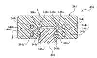
- FIG. 8 is a cross-sectional view of the Z-axis rail 346 and the Z-axis runner block 344 of the movable part support mechanism 340 cut along a plane perpendicular to the major axis of the Z-axis rail 346 (that is, the XY plane).
- FIG. 8 is a II cross-sectional view of FIG.
- the Z-axis runner block 344 is formed with a recess so as to surround the Z-axis rail 346, and in this recess, two pairs of grooves 344a extending in the axial direction of the Z-axis rail 346 are formed. 344a ′.
- a number of stainless steel balls 344b and resin retainers 344r are accommodated in the grooves 344a and 344a '.
- the retainer 344r includes a plurality of spacer portions 344rs disposed between the balls 344b and a pair of bands 344rb that connect the plurality of spacer portions 344rs.
- the ball 344b is held in a space surrounded by the plurality of spacer portions 344rs and the band 344rb.
- the Z-axis rail 346 is provided with grooves 346a and 346a ′ at positions facing the grooves 344a and 344a ′ of the Z-axis runner block 344, respectively, and the ball 344b and the retainer 344r are provided with the grooves 344a and 346a, Alternatively, it is sandwiched between the groove 344a ′ and the groove 346a ′.
- the cross-sectional shape of the grooves 344a, 344a ', 346a, 346a' is an arc shape, and the radius of curvature thereof is substantially equal to the radius of the ball 344b. Therefore, the ball 344b comes into close contact with the grooves 344a, 344a ', 346a, 346a' with almost no play.
- two pairs of ball retraction paths 344c and 344c ' are provided substantially in parallel with the grooves 344a and 344a'.
- the groove 344a ′ and the retreat path 344c ′ are connected to each other via a U-shaped path 344d ′, and the groove 344a ′, the groove 346a ′, the retreat path 344c ′, and the U-shape are connected.
- a circulation path for circulating the ball 344b and the retainer 344r is formed by the path 344d ′.
- a similar circulation path is also formed by the groove 344a, the groove 346a, and the retreat path 344c.
- the inner diameters of the retreat paths 344c and 344c 'and the U-shaped paths 344d and 344d' are slightly larger than the diameter of the ball 344b. For this reason, the frictional force generated between the retreat paths 344c and 344c 'and the U-shaped paths 344d and 344d' and the ball 344b is very small, thereby preventing the circulation of the ball 344b.
- the X-axis actuator 100 and the Y-axis actuator 200 are also provided with a movable part support mechanism (not shown).
- the movable part of the X-axis actuator 100 is supported by guide frames from both sides in two directions (Y-axis and Z-axis directions) perpendicular to the drive direction (X-axis).
- the movable part of the Y-axis actuator 200 is supported by guide frames from both sides in two directions (Z-axis and X-axis directions) perpendicular to the drive direction (Y-axis).
- the movable part is arranged with the longitudinal direction oriented horizontally.
- the movable part is cantilevered only by a rod, and the tip end side (vibration table 400 side) of the movable part hangs downward due to its own weight. This caused friction during driving and unnecessary vibration.
- the movable parts of the X-axis actuator 100 and the Y-axis actuator 200 are supported by the guide frame from below, such a problem is also solved.
- vibration device 1000 an electrodynamic biaxial vibration device 1000 (hereinafter abbreviated as “vibration device 1000”) according to a second embodiment of the present invention will be described with reference to FIGS.
- the main bodies 101, 201, and 301 (specifically, fixing portions) of the actuators are rigidly supported on the device base 50 via the fixing blocks 110, 210, and 310, respectively. ing. Therefore, the vibration of the fixed portion of each actuator is transmitted to the vibration table 400 via the apparatus base 50 and the other actuators 100, 200, 300, and can be a noise component of vibration.
- the vibration device 1000 according to the present embodiment has a configuration in which the fixed portion of each actuator is supported by the device base via an air spring in a driving direction in which strong vibration is generated. For this reason, even more accurate excitation than the excitation device 1 of the first embodiment is possible.
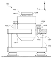
- FIG. 11 and FIG. 12 are a front view, a plan view and a side view (a view showing the left side in FIG. 10) of the vibration exciter 1000, respectively.
- the right direction in FIG. 10 is the X-axis positive direction
- the direction from the front side to the back side is the Y-axis positive direction
- the upward direction is the Z-axis positive direction
- the Z-axis direction is a vertical direction
- the X-axis and Y-axis directions are horizontal directions.
- the same reference numerals are used for the same or similar configurations as those in the first embodiment, and detailed descriptions of the common configurations are omitted.
- the vibration device 1000 is configured to be able to vibrate a specimen (not shown) in two directions, the X-axis direction and the Z-axis direction.
- the vibration table 1400 to which the specimen is attached, and the vibration table 1400 are connected to the X-axis and the vibration table 1400.
- Two actuators X-axis actuator 1100 and Z-axis actuator 1300
- the vibration table 1400 has one side surface connected to the X-axis actuator 1100 via the Z-axis slider 1160 and the lower surface connected to the Z-axis actuator 1300 via a pair of X-axis sliders 1360.
- the vibration apparatus 1000 includes a biaxial vibration pickup, a measurement unit, a control unit, an input unit, and a power supply unit (not shown).
- the internal structures of the actuators 1100 and 1300 and the configuration of the device base 1050 are the same as the configuration of the vibration device 1 of the first embodiment.
- the X-axis actuator 1100 is fixed on the top plate 1056 of the apparatus base 1050 by the support unit 1110.
- the support unit 1110 includes a pair of inverted T-shaped fixed blocks 1112 mounted on the top plate 1056 and a pair of rectangular plate-shaped movable blocks 1118 mounted on both side surfaces of the fixed portion 1120 of the X-axis actuator 1100. And a pair of linear guides 1114 for slidably connecting the fixed block 1112 and the movable block 1118 in the X-axis direction.
- Each linear guide 1114 includes a pair of rails 1114a extending in the X-axis direction attached to the upper surface of the leg 1112b of the inverted T-shaped fixed block 1112 and a pair of rails 1114a attached to the lower surface of the movable block 1118.
- a branch portion 1112a extending upward is fixed to the side surface in the X-axis positive direction of the leg portion 1112b of the fixed block 1112.
- the X-axis positive side surface of the movable block 1118 is connected to the branch portion 1112a of the fixed block 1112 via a pair of air springs 1116 arranged vertically.
- the fixing portion 1120 of the X-axis actuator is driven in the driving direction (X-axis direction) with respect to the fixing block 1112 (and thus the apparatus base 1050) by the fixing portion support mechanism including the linear guide 1114 and the air spring 1116.
- the fixing portion support mechanism including the linear guide 1114 and the air spring 1116.
- the Z-axis actuator 1300 is fixed on the top plate 1056 of the apparatus base 1050 by a pair of support units 1310 arranged on both sides in the Y-axis direction.
- the lower part of the Z-axis actuator 1300 is accommodated in the apparatus base 1050 through an opening 1057 provided in the top plate 1056 of the apparatus base 1050.
- Each support unit 1310 includes a movable block 1318, a pair of angles 1312, and a pair of linear guides 1314.
- the movable block 1318 is a support member attached to the side surface of the fixed portion 1320 of the Z-axis actuator.
- the pair of angles 1312 are disposed so as to face both end surfaces in the X-axis direction of the movable block 1318, and are attached on the top plate 1056.
- Both ends of the movable block 1318 in the X-axis direction and each angle 1312 are coupled to each other by a pair of linear guides 1314 so as to be slidable in the Z-axis direction.
- the movable block 1318 includes an angle block 1318a, a flat plate block 1318b, and a pair of T-shaped blocks 1318c.
- One mounting surface of the L-shaped angle block 1318a is fixed to the side surface of the fixed portion 1320 of the Z-axis actuator.
- a flat plate block 1318b having a substantially rectangular plate shape extending in the X-axis direction is fixed to the other attachment surface directed upward of the angle block 1318a at a substantially central portion in the length direction.
- Legs 1318d of a T-shaped block 1318c are attached to the upper surfaces of both ends in the X-axis direction of the flat block 1318b.
- Rails 1314a of linear guides 1314 extending in the Z-axis direction are attached to attachment surfaces of the T-shaped block 1318c (both end surfaces in the X-axis direction of the movable block 1318).
- Each angle 1312 is provided with a runner block 1314b that engages with an opposing rail 1314a.
- a pair of air springs 1316 sandwiched between the top plate 1056 and the flat plate block 1318b of the apparatus base 1050 are disposed on both sides in the X-axis direction of the angle block 1318a, and the movable block 1318 includes the pair of air springs 1316.
- the Z-axis actuator 1300 is also driven in the drive direction (Z-axis direction) with respect to the apparatus base 1050 by the fixed-portion support mechanism in which the fixed portion 1320 includes the linear guide 1314 and the air spring 1316 in the same manner as the X-axis actuator 1100.
- the strong reaction force (excitation force) in the Z-axis direction applied to the fixed portion 1320 when the Z-axis actuator 1300 is driven is not directly transmitted to the device base 1050, and particularly the high frequency component is greatly attenuated by the air spring 1316. Therefore, vibration noise transmitted to the vibration table 1400 is greatly reduced.
- the vibration device 1 of the first embodiment and the vibration device 1000 of the second embodiment are examples in which the present invention is applied to each actuator of a triaxial and biaxial electrodynamic vibration device, respectively.
- the present invention can also be applied to a single-axis electrodynamic excitation device.
- the movable portion 350 of the electrodynamic actuator 300 is supported from the side by the four movable portion support mechanisms 340 arranged at substantially equal intervals around the axis of the cylindrical body 322.
- the configuration of the embodiment of the present invention is not limited to this.
- the movable part is supported from the side by an arbitrary number of two or more (more preferably three or more) movable part support mechanisms arranged at substantially equal intervals around the axis of the cylindrical body. It is good also as a structure to be made.
- the runner block is fixed via the guide frame 342 fixed to the upper surface of the cylindrical body 322.
- the runner block is directly fixed to the inner peripheral surface of the cylindrical body 322. May be.
- the air springs 1116 and 1316 are used as buffer means for damping the vibration of the fixed portion support mechanism.
- springs for example, steel coils
- spring an elastic body (vibration isolation rubber, etc.), a damper device using a repulsive force of electromagnetic force, or the like can be used.
- the linear motion actuator according to the embodiment of the present invention can be used for devices other than the vibration device.
- it can be used as an actuator for a universal testing device (material testing device) for performing a tensile / compression test of a specimen, a precision positioning device, and a jack device (a heavy machine).
- the drive of each actuator is controlled using the speed of the vibration table as a control variable.
- the control may be performed using the displacement and acceleration of the vibration table as control variables.
Landscapes
- Engineering & Computer Science (AREA)
- Physics & Mathematics (AREA)
- Power Engineering (AREA)
- General Physics & Mathematics (AREA)
- Electromagnetism (AREA)
- Mechanical Engineering (AREA)
- Chemical & Material Sciences (AREA)
- Combustion & Propulsion (AREA)
- Apparatuses For Generation Of Mechanical Vibrations (AREA)
- Reciprocating, Oscillating Or Vibrating Motors (AREA)
- Investigating Strength Of Materials By Application Of Mechanical Stress (AREA)
- Vibration Prevention Devices (AREA)
- Bearings For Parts Moving Linearly (AREA)
- Control Of Position Or Direction (AREA)
- Paper (AREA)
- Audible-Bandwidth Dynamoelectric Transducers Other Than Pickups (AREA)
- Devices That Are Associated With Refrigeration Equipment (AREA)
- General Electrical Machinery Utilizing Piezoelectricity, Electrostriction Or Magnetostriction (AREA)
- Linear Motors (AREA)
Abstract
La présente invention concerne un actionneur électrodynamique doté d'une partie fixe sensiblement cylindrique ; d'une partie mobile qui est au moins partiellement accueillie à l'intérieur d'une partie vide de la partie fixe, et qui est animée d'un mouvement de va-et-vient dans le sens axial de la partie fixe ; et d'une pluralité de mécanismes de support de partie mobile qui supportent latéralement la partie mobile de façon à en permettre le mouvement de va-et-vient dans le sens axial de la partie fixe. Les mécanismes de support de la partie fixe sont disposés autour de la périphérie de l'axe de la partie fixe à des intervalles sensiblement égaux et chacun d'eux est doté d'un rail qui est monté sur la surface latérale de la partie mobile et qui s'étend dans le sens axial de la partie fixe ; et d'un patin de blocage qui est monté sur la partie fixe et qui entre en prise avec le rail.
Priority Applications (10)
| Application Number | Priority Date | Filing Date | Title |
|---|---|---|---|
| CN201280029530.8A CN103609009B (zh) | 2011-04-26 | 2012-04-19 | 电动致动器和电动激振装置 |
| KR1020207033019A KR102266234B1 (ko) | 2011-04-26 | 2012-04-19 | 동전형 액추에이터 및 가진 장치 |
| EP19207390.6A EP3624316B1 (fr) | 2011-04-26 | 2012-04-19 | Actionneur électrodynamique et dispositif d'excitation électrodynamique |
| EP23154084.0A EP4191846A1 (fr) | 2011-04-26 | 2012-04-19 | Actionneur électrodynamique et dispositif d'excitation électrodynamique |
| EP12776949.5A EP2713487A4 (fr) | 2011-04-26 | 2012-04-19 | Actionneur électrodynamique et dispositif d'excitation électrodynamique |
| KR1020137031082A KR102181674B1 (ko) | 2011-04-26 | 2012-04-19 | 동전형 액추에이터 및 동전형 가진 장치 |
| US14/060,969 US20140049122A1 (en) | 2011-04-26 | 2013-10-23 | Electrodynamic actuator and electrodynamic excitation device |
| US16/516,590 US11289991B2 (en) | 2011-04-26 | 2019-07-19 | Electrodynamic actuator and electrodynamic excitation device with movable part support mechanism and fixed part support mechanism |
| US17/672,344 US11824416B2 (en) | 2011-04-26 | 2022-02-15 | Electrodynamic actuator and electrodynamic excitation device |
| US18/377,625 US20240055968A1 (en) | 2011-04-26 | 2023-10-06 | Electrodynamic Actuator and Electrodynamic Excitation Device |
Applications Claiming Priority (4)
| Application Number | Priority Date | Filing Date | Title |
|---|---|---|---|
| JP2011-098775 | 2011-04-26 | ||
| JP2011098775 | 2011-04-26 | ||
| JP2011-238849 | 2011-10-31 | ||
| JP2011238849A JP5913910B2 (ja) | 2011-04-26 | 2011-10-31 | 直動アクチュエータ及び加振装置 |
Related Child Applications (1)
| Application Number | Title | Priority Date | Filing Date |
|---|---|---|---|
| US14/060,969 Continuation-In-Part US20140049122A1 (en) | 2011-04-26 | 2013-10-23 | Electrodynamic actuator and electrodynamic excitation device |
Publications (1)
| Publication Number | Publication Date |
|---|---|
| WO2012147607A1 true WO2012147607A1 (fr) | 2012-11-01 |
Family
ID=47072128
Family Applications (1)
| Application Number | Title | Priority Date | Filing Date |
|---|---|---|---|
| PCT/JP2012/060581 Ceased WO2012147607A1 (fr) | 2011-04-26 | 2012-04-19 | Actionneur électrodynamique et dispositif d'excitation électrodynamique |
Country Status (8)
| Country | Link |
|---|---|
| US (4) | US20140049122A1 (fr) |
| EP (3) | EP2713487A4 (fr) |
| JP (1) | JP5913910B2 (fr) |
| KR (2) | KR102266234B1 (fr) |
| CN (3) | CN105743275B (fr) |
| ES (1) | ES2949419T3 (fr) |
| TW (1) | TWI559987B (fr) |
| WO (1) | WO2012147607A1 (fr) |
Cited By (8)
| Publication number | Priority date | Publication date | Assignee | Title |
|---|---|---|---|---|
| CN105814424A (zh) * | 2013-12-12 | 2016-07-27 | 国际计测器株式会社 | 轴承测试机 |
| WO2017122770A1 (fr) * | 2016-01-15 | 2017-07-20 | 国際計測器株式会社 | Dispositif d'application de vibrations et actionneur électrodynamique |
| JP2018009982A (ja) * | 2016-06-30 | 2018-01-18 | 国際計測器株式会社 | 加振装置 |
| JP2018066658A (ja) * | 2016-10-19 | 2018-04-26 | 国際計測器株式会社 | 加振装置 |
| JP2018205322A (ja) * | 2014-07-30 | 2018-12-27 | 国際計測器株式会社 | 加振装置 |
| JP2019100764A (ja) * | 2017-11-29 | 2019-06-24 | Imv株式会社 | 振動試験装置 |
| US20240055968A1 (en) * | 2011-04-26 | 2024-02-15 | Kokusai Keisokuki Kabushiki Kaisha | Electrodynamic Actuator and Electrodynamic Excitation Device |
| CN117606858A (zh) * | 2023-11-01 | 2024-02-27 | 合肥市中心血站 | 一种白细胞提取样本制作装置及方法 |
Families Citing this family (13)
| Publication number | Priority date | Publication date | Assignee | Title |
|---|---|---|---|---|
| WO2015199633A1 (fr) * | 2014-06-27 | 2015-12-30 | Dogan Adnan | Planche d'expérimentation de tremblement de terre |
| CN104180842B (zh) * | 2014-09-02 | 2016-09-14 | 浙江大学 | 一种宽频带大位移角振动台 |
| CN104265827B (zh) * | 2014-09-08 | 2016-08-24 | 金坛市德博密封技术有限公司 | 一种用于发动机安装的三维减震安装座 |
| CN104406870A (zh) * | 2014-12-09 | 2015-03-11 | 青岛信森机电技术有限公司 | 空气弹簧疲劳试验机 |
| CN104406871A (zh) * | 2014-12-09 | 2015-03-11 | 青岛信森机电技术有限公司 | 空气弹簧垂向疲劳试验机 |
| JP6855050B2 (ja) * | 2016-01-15 | 2021-04-07 | 国際計測器株式会社 | 動電型アクチュエータ及び加振装置 |
| JP6820006B2 (ja) * | 2016-01-15 | 2021-01-27 | 国際計測器株式会社 | 加振装置、振動テーブル及び加振方法 |
| GB2558677A (en) * | 2017-02-06 | 2018-07-18 | Libertine Fpe Ltd | Linear electrical machine |
| JP7319764B2 (ja) * | 2018-07-26 | 2023-08-02 | ニデックインスツルメンツ株式会社 | アクチュエータ |
| KR102883727B1 (ko) * | 2020-06-11 | 2025-11-11 | 엘지이노텍 주식회사 | 모터 및 이를 제조하기 위한 코일 권선장치 |
| CN111551333B (zh) * | 2020-06-12 | 2024-08-16 | 苏州苏试试验集团股份有限公司 | 一种可加载拉力或压力及振动的复合式试验装置 |
| US20220397174A1 (en) * | 2021-06-12 | 2022-12-15 | Raytheon Company | Automated decoupling shock isolation for vibration couplers |
| CN116907781B (zh) * | 2023-09-13 | 2023-11-28 | 中国科学院长春光学精密机械与物理研究所 | 一种微振动模拟与主被动隔振一体化实验平台 |
Citations (5)
| Publication number | Priority date | Publication date | Assignee | Title |
|---|---|---|---|---|
| JPS50147052U (fr) * | 1974-05-23 | 1975-12-05 | ||
| JPS54143154U (fr) * | 1978-03-27 | 1979-10-04 | ||
| JPH0417510U (fr) * | 1990-06-04 | 1992-02-13 | ||
| WO2009130953A1 (fr) | 2008-04-25 | 2009-10-29 | 国際計測器株式会社 | Equipement de test par vibrations électrodynamiques |
| WO2009130818A1 (fr) * | 2008-04-24 | 2009-10-29 | 国際計測器株式会社 | Système de test de vibration électrodynamique |
Family Cites Families (71)
| Publication number | Priority date | Publication date | Assignee | Title |
|---|---|---|---|---|
| GB1546073A (en) * | 1976-05-10 | 1979-05-16 | Ready Seal Ltd | Method of repairing leaks in pipes and pipelines carrying fluent medium under pressure and means for use in the method |
| US4346762A (en) * | 1976-03-16 | 1982-08-31 | Igal Tovim | Plastics material horseshoes |
| DE2842598A1 (de) * | 1977-10-15 | 1979-04-19 | Usm Corp | Blind-befestigungselemente |
| DE2810942C3 (de) * | 1978-03-14 | 1981-04-23 | Uni-Cardan Ag, 5200 Siegburg | Dichtungsanordnung |
| US4243729A (en) * | 1978-07-31 | 1981-01-06 | Semi-Alloys, Inc. | Metallic hermetic sealing cover for a container |
| US4322121A (en) * | 1979-02-06 | 1982-03-30 | Bunker Ramo Corporation | Screw-coupled electrical connectors |
| US4438950A (en) * | 1981-02-20 | 1984-03-27 | Monarch Marking Systems, Inc. | Composite label web, price tag and re-price label combination, and method of price and re-price marking |
| US4457539A (en) * | 1981-02-20 | 1984-07-03 | Monarch Marking Systems, Inc. | Composite label web, price tag and re-price label combination, and method of price and re-price marking |
| DE3106548A1 (de) * | 1981-02-21 | 1982-09-09 | Gewerkschaft Eisenhütte Westfalia, 4670 Lünen | Schwerthobel mit mehrteiliger gelenkiger schwertplatte |
| HU184906B (en) * | 1981-12-01 | 1984-11-28 | Richter Gedeon Vegyeszet | Device for furthering liquid and separating gases sepregating from liquid |
| GB2111663B (en) * | 1981-12-16 | 1986-03-26 | Ocean Phoenix Holdings Nv | Tank for the storage and transport of pressurised fluid |
| JPS58115340A (ja) * | 1981-12-28 | 1983-07-09 | Kokusai Kikai Shindo Kenkyusho:Kk | 振動試験装置 |
| US4495582A (en) * | 1982-06-04 | 1985-01-22 | Harris Graphics Corporation | Control system for pre-setting and operation of a printing press and collator |
| DE3339708C1 (de) * | 1983-11-03 | 1985-02-28 | Goetze Ag, 5093 Burscheid | OElabstreif-Kolbenringsystem |
| US4894610A (en) * | 1985-09-14 | 1990-01-16 | LOZ Landis & Gyr Zug AG | Current-transformer arrangement for an electrostatic meter |
| JPS62152580A (ja) * | 1985-12-26 | 1987-07-07 | 株式会社 振研 | 複数方向加振機 |
| GB8619165D0 (en) * | 1986-08-06 | 1986-09-17 | Thor Hammer Co Ltd | Split head hammers |
| US4791711A (en) * | 1987-11-27 | 1988-12-20 | Simulators Limited, Inc. | Child resistant buckle for seat belt restraints |
| CH675146A5 (fr) * | 1988-02-01 | 1990-08-31 | Asea Brown Boveri | |
| US5341054A (en) * | 1988-08-31 | 1994-08-23 | Aura Systems, Inc. | Low mass electromagnetic actuator |
| US5015426A (en) * | 1989-05-18 | 1991-05-14 | Galic Maus Ventures | Precision single cavity and multicavity plastic injection molding via an adaptive mold process |
| US4981634A (en) * | 1989-05-22 | 1991-01-01 | Galic Maus Ventures | Injection molding process operating without opening the mold to airborne contaminants |
| GB2236434B (en) | 1989-09-29 | 1993-10-13 | Ling Dynamic Systems | Suspension for an electriomagnetic vibration generator |
| DE3939072A1 (de) * | 1989-11-25 | 1991-05-29 | Philips Patentverwaltung | Verfahren zum zeitverschachtelten verarbeiten von datenwoertern und anordnung zur durchfuehrung dieses verfahrens |
| US5291645A (en) * | 1989-12-01 | 1994-03-08 | Yoshitaka Aoyama | Method and apparatus for feeding and tightening threaded parts |
| US5016860A (en) * | 1990-01-31 | 1991-05-21 | Holcroft Inc. | "No-nick" part-handling apparatus and method |
| US5199093A (en) * | 1990-05-22 | 1993-03-30 | Bicc Plc. | Multi-part optical fibre connectors |
| SE469815B (sv) * | 1990-11-27 | 1993-09-27 | Moelnlycke Ab | Hölje för en absorberande artikel |
| GB9105367D0 (en) * | 1991-03-13 | 1991-04-24 | Univ Strathclyde | Computerised information-retrieval database systems |
| US5549198A (en) * | 1991-03-22 | 1996-08-27 | Basf Magnetics Gmbh | Multipack for recording media in tape form wound onto hubs |
| US5334571A (en) * | 1991-10-18 | 1994-08-02 | Moore Business Forms, Inc. | Carbonless paper for non-impact laser printing |
| NZ244699A (en) * | 1991-10-24 | 1995-04-27 | Moore Business Forms Inc | Multi-part business form: upper and lower sheets having adhesive strips, and intermediate sheets having plural apertures: strips and apertures vertically aligned |
| FR2683449A1 (fr) * | 1991-11-08 | 1993-05-14 | Cardon Alain | Endoprothese pour implantation transluminale. |
| DE4138564A1 (de) * | 1991-11-23 | 1993-05-27 | Sf Vollverbundstein | Pflastersteinsatz sowie verfahren und vorrichtung zum herstellen desselben |
| EP0544423B1 (fr) * | 1991-11-23 | 1997-02-12 | Yoshitaka Aoyama | Dispositif pour détecter des pièces, combiné avec un bâton d'alimentation d'une unité pour alimenter des pièces |
| US5231336A (en) * | 1992-01-03 | 1993-07-27 | Harman International Industries, Inc. | Actuator for active vibration control |
| US5386728A (en) * | 1992-02-24 | 1995-02-07 | Automotive Technologies International, Inc. | Vibrator for subjecting an object to vibration |
| US5456658A (en) * | 1992-03-30 | 1995-10-10 | Parker Medical Associates | Custom-fitting body part protector with cure-retarding storage system, method of constructing a body part protector, and method of custom-fitting a body part protector |
| CA2110272C (fr) * | 1992-04-04 | 2003-09-09 | Yoshitaka Aoyama | Methode utilisee pour livrer des pieces, et appareil connexe |
| US5238386A (en) * | 1992-05-20 | 1993-08-24 | Corning Incorporated | Multi-part extrusion die |
| US5293717A (en) * | 1992-07-28 | 1994-03-15 | United Technologies Corporation | Method for removal of abradable material from gas turbine engine airseals |
| SE9202466L (sv) * | 1992-08-28 | 1993-07-26 | Televerket | Foerfarande och anordning vid mobila telekommunikationsnaet foer att moejliggoera en foerbaettrad cellplanering |
| DE4234043C1 (de) * | 1992-10-09 | 1994-03-24 | Daimler Benz Ag | Bremsdruck-Steuereinrichtung für ein Straßenfahrzeug |
| AU6496594A (en) * | 1993-03-26 | 1994-10-24 | Khalil S. Zaidan | Hinge assembly for electronic devices |
| US5269533A (en) * | 1993-03-26 | 1993-12-14 | Kellams John W | Five-part support post for volleyball net |
| US5435281A (en) * | 1994-11-04 | 1995-07-25 | Chrysler Corporation | Cylinder head construction for internal combustion engines |
| JPH08136392A (ja) * | 1994-11-08 | 1996-05-31 | Shinken:Kk | 振動試験機の加振軸連結構造 |
| US5575229A (en) * | 1994-11-21 | 1996-11-19 | Blackmer; Richard | Control tackle apparatus for a sailboard rig outhaul |
| US5575488A (en) * | 1995-03-10 | 1996-11-19 | Srw Associates, Inc. | Hand-held part holder and fixture |
| US5607738A (en) * | 1995-08-29 | 1997-03-04 | Moore Business Forms, Inc. | Multiple-part carbonless pressure seal business form assembly |
| US5623174A (en) * | 1995-12-08 | 1997-04-22 | General Electric Co. | Internal grading of generator stator bars with electrically conducting thermoplastic paints |
| DE19649922A1 (de) * | 1996-12-02 | 1998-06-04 | Krupp Polysius Ag | Verfahren und Vorrichtung zur Wärmebehandlung von feinkörnigem Gut |
| SE506241C2 (sv) * | 1996-03-04 | 1997-11-24 | Ericsson Telefon Ab L M | Förfarande och anordning för bitmönsterdetektering |
| SE506471C2 (sv) * | 1996-04-03 | 1997-12-22 | Kim Silfverberg | Kopplingsstycke för isolering av ledaränddelar eller elektrisk förbindning av dito |
| US5707055A (en) * | 1996-05-20 | 1998-01-13 | Moore Business Forms, Inc. | Method and system for producing multiple part business forms |
| JP3679886B2 (ja) * | 1997-02-25 | 2005-08-03 | 株式会社ミツトヨ | 加振機における振動ピックアップの支持装置 |
| US5989028A (en) * | 1997-05-15 | 1999-11-23 | Core-Vent Corporation | Non-submergible, one-part, root-form endosseous dental implants |
| US6166465A (en) * | 1998-04-30 | 2000-12-26 | Delta Tooling Co., Ltd. | Vibration generating mechanism using repulsive forces of permanent magnets |
| JP3616058B2 (ja) * | 2002-01-25 | 2005-02-02 | 山崎 恒彦 | リニアモータ |
| JP2004253741A (ja) * | 2003-02-21 | 2004-09-09 | Sumitomo Eaton Noba Kk | 移動装置及び半導体製造装置 |
| US7069787B2 (en) * | 2003-09-29 | 2006-07-04 | Crowson Ii Randolph J | Robust low profile shaker |
| US7051593B2 (en) * | 2004-05-21 | 2006-05-30 | Ling Dynamic Systems, Inc. | Vibration testing apparatus and a method of vibration testing |
| CN101542260B (zh) * | 2007-07-19 | 2012-05-09 | 国际计测器株式会社 | 振动试验装置 |
| CN201138278Y (zh) * | 2007-12-04 | 2008-10-22 | 苏州试验仪器总厂 | 电动振动台全气密台体负载支撑结构 |
| JP4812879B2 (ja) * | 2008-05-24 | 2011-11-09 | 国際計測器株式会社 | 振動試験装置 |
| CN101414778B (zh) * | 2008-09-27 | 2010-12-01 | 北京航空航天大学 | 大振幅振动主动隔离杆 |
| WO2010098399A1 (fr) * | 2009-02-27 | 2010-09-02 | 国際計測器株式会社 | Appareil antivibratoire |
| JP5913910B2 (ja) * | 2011-04-26 | 2016-04-27 | 国際計測器株式会社 | 直動アクチュエータ及び加振装置 |
| US9482593B2 (en) * | 2014-09-17 | 2016-11-01 | King Fahd University Of Petroleum And Minerals | Selectable multi-axis shaker table |
| EP3002026A1 (fr) * | 2014-09-30 | 2016-04-06 | Shenzhen Mindray Bio-Medical Electronics Co., Ltd. | Système et procédé de stabilisation d'un moteur à bobine acoustique |
| KR102723693B1 (ko) * | 2016-01-15 | 2024-10-31 | 고쿠사이 게이소쿠키 가부시키가이샤 | 가진 장치 및 동전형 액추에이터 |
-
2011
- 2011-10-31 JP JP2011238849A patent/JP5913910B2/ja active Active
-
2012
- 2012-04-19 KR KR1020207033019A patent/KR102266234B1/ko active Active
- 2012-04-19 CN CN201610161777.5A patent/CN105743275B/zh active Active
- 2012-04-19 ES ES19207390T patent/ES2949419T3/es active Active
- 2012-04-19 EP EP12776949.5A patent/EP2713487A4/fr not_active Withdrawn
- 2012-04-19 WO PCT/JP2012/060581 patent/WO2012147607A1/fr not_active Ceased
- 2012-04-19 KR KR1020137031082A patent/KR102181674B1/ko active Active
- 2012-04-19 CN CN201280029530.8A patent/CN103609009B/zh active Active
- 2012-04-19 EP EP19207390.6A patent/EP3624316B1/fr active Active
- 2012-04-19 CN CN201610161778.XA patent/CN105728305B/zh active Active
- 2012-04-19 EP EP23154084.0A patent/EP4191846A1/fr active Pending
- 2012-04-25 TW TW101114658A patent/TWI559987B/zh active
-
2013
- 2013-10-23 US US14/060,969 patent/US20140049122A1/en not_active Abandoned
-
2019
- 2019-07-19 US US16/516,590 patent/US11289991B2/en active Active
-
2022
- 2022-02-15 US US17/672,344 patent/US11824416B2/en active Active
-
2023
- 2023-10-06 US US18/377,625 patent/US20240055968A1/en not_active Abandoned
Patent Citations (5)
| Publication number | Priority date | Publication date | Assignee | Title |
|---|---|---|---|---|
| JPS50147052U (fr) * | 1974-05-23 | 1975-12-05 | ||
| JPS54143154U (fr) * | 1978-03-27 | 1979-10-04 | ||
| JPH0417510U (fr) * | 1990-06-04 | 1992-02-13 | ||
| WO2009130818A1 (fr) * | 2008-04-24 | 2009-10-29 | 国際計測器株式会社 | Système de test de vibration électrodynamique |
| WO2009130953A1 (fr) | 2008-04-25 | 2009-10-29 | 国際計測器株式会社 | Equipement de test par vibrations électrodynamiques |
Cited By (19)
| Publication number | Priority date | Publication date | Assignee | Title |
|---|---|---|---|---|
| US20240055968A1 (en) * | 2011-04-26 | 2024-02-15 | Kokusai Keisokuki Kabushiki Kaisha | Electrodynamic Actuator and Electrodynamic Excitation Device |
| CN105814424A (zh) * | 2013-12-12 | 2016-07-27 | 国际计测器株式会社 | 轴承测试机 |
| CN105814424B (zh) * | 2013-12-12 | 2020-07-28 | 国际计测器株式会社 | 轴承测试机 |
| JP2018205322A (ja) * | 2014-07-30 | 2018-12-27 | 国際計測器株式会社 | 加振装置 |
| US10942085B2 (en) | 2016-01-15 | 2021-03-09 | Kokusai Keisokuki Kabushiki Kaisha | Oscillation device with counter balancer |
| US11898944B2 (en) | 2016-01-15 | 2024-02-13 | Kokusai Keisokuki Kabushiki Kaisha | Oscillation device with a vibrating table that houses an oscillated object |
| US12442715B2 (en) | 2016-01-15 | 2025-10-14 | Kokusai Keisokuki Kabushiki Kaisha | Oscillation device with counter balancer |
| CN112161772A (zh) * | 2016-01-15 | 2021-01-01 | 国际计测器株式会社 | 激振装置和振动台 |
| WO2017122770A1 (fr) * | 2016-01-15 | 2017-07-20 | 国際計測器株式会社 | Dispositif d'application de vibrations et actionneur électrodynamique |
| JP2018009982A (ja) * | 2016-06-30 | 2018-01-18 | 国際計測器株式会社 | 加振装置 |
| JP7250395B1 (ja) | 2016-06-30 | 2023-04-03 | 国際計測器株式会社 | 加振装置 |
| JP2023054325A (ja) * | 2016-06-30 | 2023-04-13 | 国際計測器株式会社 | 加振装置 |
| JP2023145752A (ja) * | 2016-06-30 | 2023-10-11 | 国際計測器株式会社 | 加振装置 |
| JP7634902B2 (ja) | 2016-06-30 | 2025-02-25 | 国際計測器株式会社 | 加振装置 |
| JP2018066658A (ja) * | 2016-10-19 | 2018-04-26 | 国際計測器株式会社 | 加振装置 |
| JP7073080B2 (ja) | 2017-11-29 | 2022-05-23 | Imv株式会社 | 振動試験装置 |
| JP2019100764A (ja) * | 2017-11-29 | 2019-06-24 | Imv株式会社 | 振動試験装置 |
| CN117606858A (zh) * | 2023-11-01 | 2024-02-27 | 合肥市中心血站 | 一种白细胞提取样本制作装置及方法 |
| CN117606858B (zh) * | 2023-11-01 | 2024-05-10 | 合肥市中心血站 | 一种白细胞提取样本制作装置及方法 |
Also Published As
| Publication number | Publication date |
|---|---|
| CN105743275A (zh) | 2016-07-06 |
| CN105728305A (zh) | 2016-07-06 |
| TWI559987B (en) | 2016-12-01 |
| US20240055968A1 (en) | 2024-02-15 |
| KR102266234B1 (ko) | 2021-06-17 |
| KR102181674B1 (ko) | 2020-11-23 |
| US11824416B2 (en) | 2023-11-21 |
| US20190341837A1 (en) | 2019-11-07 |
| EP2713487A4 (fr) | 2016-03-16 |
| ES2949419T3 (es) | 2023-09-28 |
| CN103609009B (zh) | 2017-03-29 |
| US11289991B2 (en) | 2022-03-29 |
| EP3624316B1 (fr) | 2023-04-19 |
| US20140049122A1 (en) | 2014-02-20 |
| CN105728305B (zh) | 2019-08-16 |
| KR20200135546A (ko) | 2020-12-02 |
| CN103609009A (zh) | 2014-02-26 |
| EP4191846A1 (fr) | 2023-06-07 |
| EP3624316A1 (fr) | 2020-03-18 |
| CN105743275B (zh) | 2020-08-18 |
| JP2012237736A (ja) | 2012-12-06 |
| KR20140028024A (ko) | 2014-03-07 |
| EP2713487A1 (fr) | 2014-04-02 |
| US20220173647A1 (en) | 2022-06-02 |
| TW201249548A (en) | 2012-12-16 |
| JP5913910B2 (ja) | 2016-04-27 |
Similar Documents
| Publication | Publication Date | Title |
|---|---|---|
| JP5913910B2 (ja) | 直動アクチュエータ及び加振装置 | |
| JP6653735B2 (ja) | 加振装置 | |
| JP6416971B2 (ja) | 動電型アクチュエータ及び動電型加振装置 | |
| CN204953280U (zh) | 电动型致动器和激振装置 |
Legal Events
| Date | Code | Title | Description |
|---|---|---|---|
| 121 | Ep: the epo has been informed by wipo that ep was designated in this application |
Ref document number: 12776949 Country of ref document: EP Kind code of ref document: A1 |
|
| DPE1 | Request for preliminary examination filed after expiration of 19th month from priority date (pct application filed from 20040101) | ||
| NENP | Non-entry into the national phase |
Ref country code: DE |
|
| ENP | Entry into the national phase |
Ref document number: 20137031082 Country of ref document: KR Kind code of ref document: A |
|
| WWE | Wipo information: entry into national phase |
Ref document number: 2012776949 Country of ref document: EP |