WO2009133705A1 - Pompe d'acheminement de liquide - Google Patents
Pompe d'acheminement de liquide Download PDFInfo
- Publication number
- WO2009133705A1 WO2009133705A1 PCT/JP2009/001952 JP2009001952W WO2009133705A1 WO 2009133705 A1 WO2009133705 A1 WO 2009133705A1 JP 2009001952 W JP2009001952 W JP 2009001952W WO 2009133705 A1 WO2009133705 A1 WO 2009133705A1
- Authority
- WO
- WIPO (PCT)
- Prior art keywords
- infusion
- valve
- infusion tube
- handle
- tube
- Prior art date
- Legal status (The legal status is an assumption and is not a legal conclusion. Google has not performed a legal analysis and makes no representation as to the accuracy of the status listed.)
- Ceased
Links
Images



Classifications
-
- F—MECHANICAL ENGINEERING; LIGHTING; HEATING; WEAPONS; BLASTING
- F04—POSITIVE - DISPLACEMENT MACHINES FOR LIQUIDS; PUMPS FOR LIQUIDS OR ELASTIC FLUIDS
- F04B—POSITIVE-DISPLACEMENT MACHINES FOR LIQUIDS; PUMPS
- F04B43/00—Machines, pumps, or pumping installations having flexible working members
- F04B43/12—Machines, pumps, or pumping installations having flexible working members having peristaltic action
-
- A—HUMAN NECESSITIES
- A61—MEDICAL OR VETERINARY SCIENCE; HYGIENE
- A61M—DEVICES FOR INTRODUCING MEDIA INTO, OR ONTO, THE BODY; DEVICES FOR TRANSDUCING BODY MEDIA OR FOR TAKING MEDIA FROM THE BODY; DEVICES FOR PRODUCING OR ENDING SLEEP OR STUPOR
- A61M39/00—Tubes, tube connectors, tube couplings, valves, access sites or the like, specially adapted for medical use
- A61M39/22—Valves or arrangement of valves
- A61M39/28—Clamping means for squeezing flexible tubes, e.g. roller clamps
- A61M39/281—Automatic tube cut-off devices, e.g. squeezing tube on detection of air
-
- A—HUMAN NECESSITIES
- A61—MEDICAL OR VETERINARY SCIENCE; HYGIENE
- A61M—DEVICES FOR INTRODUCING MEDIA INTO, OR ONTO, THE BODY; DEVICES FOR TRANSDUCING BODY MEDIA OR FOR TAKING MEDIA FROM THE BODY; DEVICES FOR PRODUCING OR ENDING SLEEP OR STUPOR
- A61M5/00—Devices for bringing media into the body in a subcutaneous, intra-vascular or intramuscular way; Accessories therefor, e.g. filling or cleaning devices, arm-rests
- A61M5/14—Infusion devices, e.g. infusing by gravity; Blood infusion; Accessories therefor
- A61M5/142—Pressure infusion, e.g. using pumps
- A61M5/14212—Pumping with an aspiration and an expulsion action
- A61M5/14228—Pumping with an aspiration and an expulsion action with linear peristaltic action, i.e. comprising at least three pressurising members or a helical member
-
- F—MECHANICAL ENGINEERING; LIGHTING; HEATING; WEAPONS; BLASTING
- F04—POSITIVE - DISPLACEMENT MACHINES FOR LIQUIDS; PUMPS FOR LIQUIDS OR ELASTIC FLUIDS
- F04B—POSITIVE-DISPLACEMENT MACHINES FOR LIQUIDS; PUMPS
- F04B43/00—Machines, pumps, or pumping installations having flexible working members
- F04B43/08—Machines, pumps, or pumping installations having flexible working members having tubular flexible members
- F04B43/082—Machines, pumps, or pumping installations having flexible working members having tubular flexible members the tubular flexible member being pressed against a wall by a number of elements, each having an alternating movement in a direction perpendicular to the axes of the tubular member and each having its own driving mechanism
-
- F—MECHANICAL ENGINEERING; LIGHTING; HEATING; WEAPONS; BLASTING
- F04—POSITIVE - DISPLACEMENT MACHINES FOR LIQUIDS; PUMPS FOR LIQUIDS OR ELASTIC FLUIDS
- F04B—POSITIVE-DISPLACEMENT MACHINES FOR LIQUIDS; PUMPS
- F04B49/00—Control, e.g. of pump delivery, or pump pressure of, or safety measures for, machines, pumps, or pumping installations, not otherwise provided for, or of interest apart from, groups F04B1/00 - F04B47/00
- F04B49/10—Other safety measures
Definitions
- the present invention relates to an infusion pump used for, for example, a medical infusion device, and more specifically, obstruction of a tube for preventing a free flow of liquid caused by a tube that sends the liquid remaining open.
- the present invention relates to an infusion pump having a mechanism.
- the infusion pump provided with a door that can be opened and closed with respect to an infusion pump body incorporating a pump mechanism, a peristaltic system Is mainly used.
- Patent Document 1 discloses a structure in which liquid feeding is performed by sequentially pressing the infusion tube to the downstream side.
- Patent Document 2 The method disclosed in Patent Document 2 has been proposed as an example of an infusion pump having a function of preventing this free flow.
- the infusion tube is provided with a mechanism that closes the infusion tube at the same time that the door is opened, and if the infusion tube is not closed by a predetermined closing member, Because it has a structure that cannot be removed, it was excellent in safety by preventing free flow.
- the safety clamp when opening the safety clamp, the operator presses a part of the safety clamp mechanism with his / her finger, but the safety clamp uses a strong spring to ensure that the tube is closed. Therefore, there is a case where a heavy load is applied depending on the operator.
- the safety clamp can be opened automatically or semi-automatically using a motor or the like as a drive source in order to reduce the load and reduce the burden on the operator, the number of parts will increase and the necessary internal structure There will be negative effects such as “increase in space”, “does not work when power supply is not working", and "high cost”.
- the safety clamp when removing the tube, the safety clamp can be pushed with a finger before closing the tube with the slide clamp, so if the operator makes a mistake, a free flow occurs. Problem.
- the invention according to claim 1 is an infusion pump for delivering the liquid in the infusion tube, the infusion pump comprising a pump body and a door unit that can be opened and closed with respect to the pump body. It is supposed to consist of The detailed structure is as follows.
- the door unit constitutes a door mechanism, and the door mechanism has a door pivotally supported by the pump body and an engaging portion with the pump body.
- the door unit is pivotally supported by the door and rotates within a certain range. And a movable handle.
- the pump body comprises a liquid feeding mechanism part, a slide clamp mechanism part, a valve mechanism part, and an interlocking mechanism part, and this liquid feeding mechanism part is provided with a drive part that presses the infusion tube by a reciprocating motion. It is.
- the slide clamp mechanism has a structure including a clamp holding part that holds a clamp member that closes or opens the infusion tube and a clamp moving part that moves the position of the clamp member.
- the valve mechanism has a structure including a valve capable of compressing the infusion tube and blocking the liquid flow path in the infusion tube.
- the interlocking mechanism part has a structure including a plurality of links that transmit the force acting by the turning operation of the handle to the slide clamp mechanism part and the valve mechanism part.
- the clamp member closes or opens the infusion tube by the force that acts when the handle is engaged with the pump body and the handle is rotated.
- the valve compresses the infusion tube to block the liquid flow path in the infusion tube, or releases the compression of the infusion tube to open the liquid flow path in the infusion tube. Yes.
- the clamp member closes the infusion tube, and the valve does not compress the infusion tube.
- the force acting when the handle is rotated from one of the limit positions within the range in which the handle can be rotated to the other acts on the plurality of links of the interlocking mechanism portion.
- At least one or more of the links act on the valve mechanism, the valve compresses the tube, and then at least one or more of the links acts on the slide clamp mechanism, The clamp moving component moves the clamp member from the closed position to the open position.
- the clamp member opens the infusion tube, and from the state where the valve compresses the infusion tube, the handle is engaged with the pump body, and the handle can be rotated from one limit position to the other.
- a force acting when rotating acts on the plurality of links of the interlocking mechanism portion.
- At least one link acts on the slide clamp mechanism, and the clamp moving part moves the clamp member from the open position to the closed position, and then at least one link is the valve.
- the valve acts as an infusion pump characterized by releasing the compression of the tube by acting on the mechanism portion.
- the drive part of the liquid feeding mechanism is substantially V-shaped along the liquid feeding direction of the liquid in the tube.
- the groove portion is formed.
- the door part of the door mechanism part is provided with an opposing part in which a substantially V-shaped groove is formed at a position facing the driving part with the door unit closed. At least one or more valves are arranged on both sides of the drive component at a position where the infusion tube can be closed.
- the drive component reciprocates in a direction perpendicular to the liquid feeding direction and parallel to the facing door unit, so that the drive component and the opposed component repeatedly press the infusion tube, and the infusion tube
- the infusion pump is characterized in that the valve operates to feed the liquid in the tube in accordance with the timing of repeatedly pressing.
- the drive part of the liquid feeding mechanism section is constituted by a plurality of finger parts.
- the infusion pump is characterized.
- the slide clamp mechanism and the valve mechanism are operated in conjunction with each other only by operating the handle.
- the interlocking mechanism portion has a link mechanism portion having a plurality of degrees of freedom and a movable range in the triaxial direction.
- the infusion pump is characterized in that a spring for energizing the interlocking mechanism portion is disposed at at least one place of the pump body.
- the slide clamp mechanism and the valve mechanism are operated in an interlocked manner only by operating the handle.
- the mechanism portion has a structure including a combination of a plurality of links including a link having a groove cam or a slider portion.
- linkage mechanism part is set as the infusion pump characterized by arrange
- the operator when the door unit is opened with respect to the pump body, the operator does not manually open and close the valve corresponding to the safety clamp of the prior art. Will not occur.
- the link mechanism that works like a lever without using power that requires a power source such as a motor allows the operator to operate the mechanism for closing and opening the infusion tube with a relatively small force.
- the infusion tube when the infusion tube is attached to and detached from the infusion pump, the infusion tube is always closed by the clamp member or the valve or both of the clamp member and the valve. Can be reliably prevented.
- the valve is in a state of closing the tube, but there is one driving component for pressing the infusion tube. Therefore, a simple structure can be used to open the valve in a timely manner during liquid feeding.
- each component constituting the interlocking mechanism is placed at a predetermined place. Can be positioned.
- the spring force acts on the handle via the link, and the door unit is closed to the pump body. Since the handle rotates in the opposite direction, the operator or the like can easily recognize that the door unit is not completely closed with respect to the pump body.
- the timing at which the slide clamp mechanism and the valve mechanism function can be determined by one link.
- FIG. 1 is a perspective view of an infusion pump 100 according to Embodiment 1 of the present invention.
- the infusion pump 100 is roughly composed of a pump main body 10 and a door unit 20 that can be opened and closed with respect to the pump main body 10.
- FIG. 1 (a) shows a state in which the door unit is open.
- (B) has shown the state in which the door unit is closed.
- the infusion tube 40 is closed by the slide clamp 30 and the infusion tube 40 is assembled into the pump body, and then the door unit shown in FIG.
- the infusion tube is closed / opened by the function of the valve mechanism and the slide clamp mechanism in conjunction with a series of operations of the handle 23 in the process of closing the valve.
- both or one of the slide clamp 30 and the valves 14 ⁇ / b> A and 14 ⁇ / b> B closes the infusion tube 40, and the liquid in the infusion tube 40 is free. Flow can be completely prevented.
- the slide clamp 30 and the valves 14A and 14B close or open the infusion tube 40 in the state shown in the table below with respect to the position of the handle 23 shown in FIGS. 6 (a) to 6 (d).
- the pump body 10 includes a valve mechanism unit including a valve 14A and a valve 14B, a slide clamp mechanism unit 15, and an interlocking mechanism unit 13 disposed on a base plate 11, and a shuttle mechanism unit including a V-groove drive component 12A and a motor 16. Is configured as the main part.
- the door unit 20 includes a handle 23 and a V-groove fixed component 22 arranged on the door component 21 as main parts.
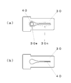
- FIG. 2A is a plan view of the slide clamp 30 used as a clamp member for closing the infusion tube 40.
- the slide clamp 30 has a through groove whose groove width changes from the narrow groove part 30n to the wide groove part 30w.
- the narrow groove 30n has a width smaller than twice the wall thickness of the infusion tube 40, and the wide groove 30w is larger than the infusion tube. Therefore, when the infusion tube is placed at the position of the narrow groove 30n, FIG. ) When the infusion tube 40 is closed and placed at the position of the wide groove 30w, the infusion tube 40 can be opened as shown in FIG.
- the V-groove drive component 12A is parallel to the V-groove fixed component 22 which is perpendicular to the liquid feeding direction Y and is opposed to the motor 16 as a drive source.
- a shuttle-type liquid feeding mechanism is employed in which the liquid in the tube is fed by repeatedly pressing the V-groove-shaped fixing part 22 and the infusion tube.
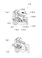
- FIG. 3 shows the structure of the slide clamp mechanism 15.
- the slide clamp mechanism unit 15 includes slide parts 15A, arms 15B and 15C, an arm spring 15D, a slider case 15E, and a slider spring 15F as main components.
- FIG. 3 (a) shows a state in which the slide clamp 30 in which the infusion tube 40 is closed with the narrow groove portion 30n is attached to the slide clamp mechanism portion 15.
- each of the arms 15B and 15C is positioned in the narrow portion 15En of the slider case 15E.
- each of the arms 15B and 15C is urged only by the arm spring 15D by leaving the narrow portion 15En of the slider case 15E, and the arms 15B and 15C hold the slide clamp 30.
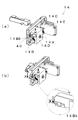
- FIG. 4 shows the structure of the valve mechanism section 14.
- the valve mechanism section 14 includes valves 14A and 14B, valve cams 14C and 14D, and a valve cam shaft 14E as main components.
- FIG. 4A shows a state where the valves 14A and 14B are opened. That is, the blocking portions 14Ab (see FIG. 7) and 14Bb of the infusion tube 40 of the valves 14A and 14B compress the infusion tube 40 in the X direction in FIG. There is no state.
- valve camshaft 14E By rotating the valve camshaft 14E from the state of FIG. 4A, the positions of the valve cams 14C and 14D integrated with the valve camshaft 14E are changed to positions for urging the valves 14A and 14B.
- the 40 closed portions 14Ab and 14Bb are moved in the X direction.
- valves 14A and 14B compress the infusion tube and block the flow path, that is, the valves 14A and 14B are closed.
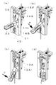
- FIG. 5 shows the structure of the interlocking mechanism 13.
- the interlocking mechanism unit 13 includes five links including links 13A, 13B, 13C, 13D, and 13E as main components.
- the five links composed of the links 13A, 13B, 13C, 13D, and 13E are connected to form a link mechanism having a plurality of degrees of freedom and a spatial movable range in three axial directions.
- the link 13C acts on the slide part 15A of the slide clamp mechanism portion 15, and the link 13E acts on the valve camshaft 14E of the valve mechanism portion 14.
- FIG. 5A shows a state in which the slide clamp 30 with the infusion tube 40 closed is attached to the slide clamp mechanism section 15 and the valves 14A and 14B are opened in the valve mechanism section 14. At this time, the link of the interlock mechanism section 13 is shown. No external force acts on the position of 13Ai, which is one end of 13A.
- the link 13E acts on the valve camshaft 14E of the valve mechanism 14 to close the valves 14A and 14B, and then the link 13C slides. Acting on the slide part 15 ⁇ / b> A of the clamp mechanism 15, the slide clamp 30 opens the infusion tube 40.
- the link 13C is connected to the slide part 15A of the slide clamp mechanism unit 15. After the slide clamp 30 closes the infusion tube 40, the link 13E acts on the valve camshaft 14E of the valve mechanism 14 to open the valves 14A and 14B.
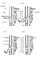
- FIGS. 6A to 6D portions other than the handle 23 in the door unit 20 are omitted.
- the handle 23 is in the position shown in FIG. 6 (a) by receiving the load of the slider spring 15F via the link 13A. At this time, no other external force is applied to the handle 23.
- the slide clamp 30 is in a position to close the infusion tube 40 (see FIG. 3A), and the valves 14A and 14B are in an open state (see FIGS. 4A and 5A).
- an external force F is applied to the handle 23, and the external force F acts on the interlocking mechanism portion 13 via a portion of one end 13Ai of the link 13A.
- the slide clamp 30 is in a position to close the infusion tube 40 (see FIG. 3A), and the valves 14A and 14B are in an open state (see FIG. 4A).
- the slide clamp 30 is in a position to open the infusion tube 40 (see FIG. 3 (b)), and the valves 14A and 14B are closed (see FIG. 4 (b)).
- FIG. 6 (d) ⁇ FIG. 6 (c) ⁇ FIG. ) ⁇ The slide clamp 30 and the valves 14A and 14B operate to close or open the infusion tube 40 in the order of the state shown in FIG.
- both or one of the valves 14A and 14B of the slide clamp 30 is in a state of closing the infusion tube 40, and infusion The free flow of the liquid in the tube 40 can be completely prevented.
- valves 14A and 14B are in a state of closing the infusion tube 40. Need to open the valves 14A and 14B in a timely manner.
- the infusion pump 100 of this embodiment has a shuttle type liquid feeding mechanism.
- this shuttle system By adopting this shuttle system, it is possible to open the valves 14A and 14B in a timely manner with a simple structure during liquid feeding.
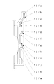
- FIG. 7 is a view showing the structure of the shuttle mechanism 12 of the infusion pump 100.
- the pump cam 12B that rotates by the driving force of the motor 16 is formed with a cam surface 12Bs that determines the motion trajectory of the V-groove drive component 12A and a cam surface 12Bv that acts on the valves 14A and 14B.
- valves 14A and 14B perform opening and closing operations at the respective timings in accordance with the timing of the reciprocating motion of the V-groove-shaped drive component 12A, so that liquid can be fed appropriately.
- the position of the pump cam 12B is electrically controlled so that both the valves 14A and 14B are closed.
- the pump cam 12B does not stop at a predetermined position due to a control problem.
- the cam surface 12Bv is formed so that one of the valves 14A and 14B is always closed.
- the infusion pump 100 realizes a structure in which an infusion tube can be attached and detached by a simple operation while reliably preventing free flow by a relatively simple component configuration.
- FIG. 1 ⁇ Embodiment 2> 8 (a) to 8 (d) are side views of the infusion pump 200 according to the second embodiment of the present invention.
- the infusion pump 200 is characterized in that the interlocking mechanism portion 13 has a link 13F having a groove cam having the shape shown in FIG.
- the infusion pump 200 As with the infusion pump 100 according to the first embodiment, the infusion pump 200 according to the present example always uses both the valves 14A and 14B of the slide clamp 30 or both during the operation to open and close the door unit 20 by a series of operations of the handle 24. On the other hand, the infusion tube 40 is closed, and the free flow of the liquid in the infusion tube 40 can be completely prevented.
- the slide clamp 30 and the valves 14A and 14B close or open the infusion tube 40 in the state shown in the table below with respect to the position of the handle 24 shown in FIGS. 8 (a) to (d).
- the slide clamp mechanism unit 15 (see FIG. 3) and the valve mechanism unit 14 (see FIG. 4) other than the interlocking mechanism unit 13 have the same basic configuration as that of the first embodiment.
- a force is applied to the link 13F by the operation of the handle 24, and the link 13G, the link 13H, and the link 13J operate according to the groove cam shape of the link 13F, whereby the slide clamp mechanism unit 15 and the valve mechanism unit 14 are operated. Are linked.
- the handle 24 is lifted by the action of a spring (not shown) provided in the door unit. At this time, no other external force is applied to the handle 24.
- the slide clamp 30 is in a position to close the infusion tube 40 (see FIG. 3A), and the valves 14A and 14B are in an open state (see FIGS. 4A and 5A).
- an external force F is applied to the handle 24, and the external force F acts on the interlocking mechanism portion 13 through the portion 13Fn of the link 13F.
- the slide clamp 30 is in a position to close the infusion tube 40 (see FIG. 3A), and the valves 14A and 14B are in an open state (see FIG. 4A).
- valve camshaft 14E is rotated by the action of the link 13J and the link 13H, whereby the valves 14A and 14B are closed (see FIG. 4B), and the slide clamp 30 closes the infusion tube 40. In position. [See FIG. 3 (a)].
- the slide clamp 30 is in a position to open the infusion tube 40 (see FIG. 3 (b)), and the valves 14A and 14B are closed (see FIG. 4 (b)).
- both or one of the valves 14A and 14B of the slide clamp 30 is in a state of closing the infusion tube 40, and the infusion The free flow of the liquid in the tube 40 can be completely prevented.
- the infusion pump of this example was a peristaltic infusion pump.
- the structure of a peristaltic infusion pump is described in Patent Document 1.
- This mechanism that opens and closes the valve independently is activated as a switch by an electrical signal transmitted at the start and stop of liquid feeding, and the valve is opened when liquid feeding and closed when liquid feeding is stopped.
- the interlocking mechanism unit is not limited to the mechanism of the first embodiment and the second embodiment, and the slide clamp mechanism can be operated only by operating the handle by various combinations of element parts such as a link, a cam, a slider, and a spring.
- a mechanism that functions in conjunction with the valve mechanism can be configured.
- the infusion system is not limited to the shuttle system and the peristaltic system, and any infusion pump can be used as long as it is equipped with a door and a handle and delivers the liquid in the infusion tube with the door closed. Mechanisms can be applied.
- FIG. 3 is a structural diagram showing a slide clamp mechanism according to an embodiment of the present invention.
- 1 is a structural diagram showing a valve mechanism according to an embodiment of the present invention.
- It is a structural diagram showing an interlocking mechanism according to an embodiment of the present invention.
- It is a figure which shows the position of a handle, the state of a slide clamp, and a valve
- It is a structural diagram showing a liquid feeding mechanism according to an embodiment of the present invention. It is a figure which shows the positional relationship of a handle
Landscapes
- Engineering & Computer Science (AREA)
- Health & Medical Sciences (AREA)
- Mechanical Engineering (AREA)
- General Engineering & Computer Science (AREA)
- Heart & Thoracic Surgery (AREA)
- Hematology (AREA)
- Anesthesiology (AREA)
- Biomedical Technology (AREA)
- Life Sciences & Earth Sciences (AREA)
- Animal Behavior & Ethology (AREA)
- General Health & Medical Sciences (AREA)
- Public Health (AREA)
- Veterinary Medicine (AREA)
- Pulmonology (AREA)
- Vascular Medicine (AREA)
- Infusion, Injection, And Reservoir Apparatuses (AREA)
- Reciprocating Pumps (AREA)
Abstract
Priority Applications (5)
| Application Number | Priority Date | Filing Date | Title |
|---|---|---|---|
| JP2010510044A JP5463468B2 (ja) | 2008-04-30 | 2009-04-30 | 輸液ポンプ |
| HK11108753.7A HK1154525B (en) | 2008-04-30 | 2009-04-30 | Liquid conveying pump |
| EP09738642.9A EP2272552B1 (fr) | 2008-04-30 | 2009-04-30 | Pompe d'acheminement de liquide |
| CA2716203A CA2716203C (fr) | 2008-04-30 | 2009-04-30 | Pompe d'acheminement de liquide |
| CN200980112634.3A CN101990446B (zh) | 2008-04-30 | 2009-04-30 | 输液泵 |
Applications Claiming Priority (2)
| Application Number | Priority Date | Filing Date | Title |
|---|---|---|---|
| US12/112,247 | 2008-04-30 | ||
| US12/112,247 US9028456B2 (en) | 2008-04-30 | 2008-04-30 | Infusion pump |
Publications (1)
| Publication Number | Publication Date |
|---|---|
| WO2009133705A1 true WO2009133705A1 (fr) | 2009-11-05 |
Family
ID=41254929
Family Applications (1)
| Application Number | Title | Priority Date | Filing Date |
|---|---|---|---|
| PCT/JP2009/001952 Ceased WO2009133705A1 (fr) | 2008-04-30 | 2009-04-30 | Pompe d'acheminement de liquide |
Country Status (6)
| Country | Link |
|---|---|
| US (1) | US9028456B2 (fr) |
| EP (1) | EP2272552B1 (fr) |
| JP (1) | JP5463468B2 (fr) |
| CN (1) | CN101990446B (fr) |
| CA (1) | CA2716203C (fr) |
| WO (1) | WO2009133705A1 (fr) |
Cited By (11)
| Publication number | Priority date | Publication date | Assignee | Title |
|---|---|---|---|---|
| USD635255S1 (en) | 2010-08-06 | 2011-03-29 | WalkMed Infusion LLC | Combination slide clamp and occlusion clamp actuator |
| WO2012161194A1 (fr) * | 2011-05-26 | 2012-11-29 | ニプロ株式会社 | Pompe à perfusion |
| US8465464B2 (en) | 2010-08-06 | 2013-06-18 | WalkMed Infusion LLC | Infusion pump and slide clamp apparatus and method |
| WO2014077309A1 (fr) | 2012-11-14 | 2014-05-22 | 並木精密宝石株式会社 | Structure de clampage de tube pour pompe à tubulure |
| WO2014123178A1 (fr) | 2013-02-06 | 2014-08-14 | 並木精密宝石株式会社 | Pompe de tubage |
| US9017297B2 (en) | 2010-08-06 | 2015-04-28 | WalkMed Infusion LLC | Infusion pump and method which inhibits unintended tubing withdrawal |
| JPWO2013145060A1 (ja) * | 2012-03-26 | 2015-08-03 | テルモ株式会社 | 輸液ポンプ |
| JPWO2014077308A1 (ja) * | 2012-11-14 | 2017-01-05 | 並木精密宝石株式会社 | チュービングポンプ |
| WO2020246821A3 (fr) * | 2019-06-05 | 2021-01-21 | 가톨릭대학교 산학협력단 | Dispositif d'injection de médicament extensible et mode de fonctionnement |
| CN117462786A (zh) * | 2023-09-25 | 2024-01-30 | 东莞恒丰医疗科技有限公司 | 一种输液泵泵门、输液泵及其输液管安装方法 |
| US12616789B2 (en) | 2019-06-05 | 2026-05-05 | The Catholic University Of Korea Industry-Academic Cooperation Foundation | Extensible drug injection device and operation method therefor |
Families Citing this family (29)
| Publication number | Priority date | Publication date | Assignee | Title |
|---|---|---|---|---|
| WO2010101783A2 (fr) * | 2009-03-06 | 2010-09-10 | Deka Products Limited Partnership | Dispositifs et procédés pour occlure un tube souple |
| WO2012112920A1 (fr) | 2011-02-19 | 2012-08-23 | Shipman Douglas | Pompe améliorée, procédé d'utilisation et procédé de fabrication |
| JP2014533581A (ja) | 2011-11-23 | 2014-12-15 | ザ ジェネラル ホスピタル コーポレイション | 注入ポンプによる薬剤送達の予測、視覚化、および制御 |
| CN103120817B (zh) * | 2013-02-04 | 2015-04-01 | 深圳麦科田生物医疗技术有限公司 | 一种电动控制止液夹的输液泵 |
| US10226571B2 (en) | 2013-03-14 | 2019-03-12 | Carefusion 303, Inc. | Pump segment placement |
| WO2014159466A1 (fr) * | 2013-03-14 | 2014-10-02 | Carefusion 303, Inc. | Ensemble de perfusion jetable |
| US9968739B2 (en) | 2013-03-14 | 2018-05-15 | Carefusion 303, Inc. | Rotary valve for a disposable infusion set |
| US9468714B2 (en) * | 2013-03-14 | 2016-10-18 | Carefusion 303, Inc. | Memory and identification associated with IV set |
| US9522224B2 (en) | 2013-03-14 | 2016-12-20 | Carefusion 303, Inc. | Inductively powered modular medical device system |
| CN104162199B (zh) * | 2013-05-16 | 2017-04-19 | 深圳市深科医疗器械技术开发有限公司 | 一种用于输液泵的止液装置 |
| WO2015175757A1 (fr) | 2014-05-15 | 2015-11-19 | The General Hospital Corporation | Prédiction, visualisation et commande de l'administration de médicament par des pompes à perfusion multiples |
| CN105311704B (zh) * | 2015-11-20 | 2018-04-10 | 深圳影迈科技股份有限公司 | 输液泵 |
| CN105311703B (zh) * | 2015-11-20 | 2018-08-03 | 深圳影迈科技股份有限公司 | 输液泵 |
| CN105343964B (zh) * | 2015-11-20 | 2018-10-23 | 深圳影迈科技有限公司 | 输液泵 |
| EP4335471A3 (fr) * | 2016-01-28 | 2024-08-21 | DEKA Products Limited Partnership | Appareil de surveillance, de régulation ou de régulation d'écoulement de fluide |
| EP3471796B1 (fr) * | 2016-06-16 | 2023-09-13 | Smiths Medical ASD, Inc. | Ensembles et procédés pour ensembles d'administration de système de pompe à perfusion |
| EP3562530B1 (fr) | 2016-12-30 | 2021-05-05 | Baxter International, Inc. | Joint pour la porte d'une pompe d'infusion pour des conduits d'infusion verticaux |
| EP3838311B1 (fr) | 2016-12-30 | 2025-05-07 | Baxter International Inc. | Orifice de tube intraveineux anti-occlusion |
| DE102017103852A1 (de) | 2017-02-24 | 2018-08-30 | B. Braun Melsungen Aktiengesellschaft | Sicherheits-Fluidleitungssystem für eine medizintechnische Schlauchpumpe, Schlauchpumpe sowie Einheit daraus |
| USD859123S1 (en) * | 2017-07-13 | 2019-09-10 | Jcb Access Limited | Door handle |
| DE102017116106A1 (de) * | 2017-07-18 | 2019-01-24 | B. Braun Melsungen Ag | Vorrichtung und Verfahren zum Öffnen und Schließen einer Infusionsschlauchklemme |
| JP7295840B2 (ja) | 2017-07-19 | 2023-06-21 | スミスズ メディカル エーエスディー,インコーポレイティド | 輸液ポンプのためのハウジング構造 |
| USD870263S1 (en) | 2017-07-26 | 2019-12-17 | Smiths Medical Asd, Inc. | Infusion set |
| CN111201051B (zh) | 2017-08-10 | 2022-04-01 | 西医药服务以色列有限公司 | 注射器药筒门锁定机构 |
| EP3787733A1 (fr) * | 2018-05-04 | 2021-03-10 | Fresenius Vial SAS | Dispositif de perfusion comprenant un dispositif de serrage |
| USD917045S1 (en) | 2018-08-16 | 2021-04-20 | Deka Products Limited Partnership | Slide clamp |
| CN109821098B (zh) * | 2019-03-01 | 2021-05-28 | 浙江师范大学 | 一种压电叠堆驱动式输液装置 |
| USD1004412S1 (en) | 2019-08-16 | 2023-11-14 | Deka Products Limited Partnership | Slide clamp assembly |
| CN112717231A (zh) * | 2020-12-31 | 2021-04-30 | 深圳市好克医疗仪器股份有限公司 | 一种输液泵 |
Citations (5)
| Publication number | Priority date | Publication date | Assignee | Title |
|---|---|---|---|---|
| JPH05277183A (ja) | 1992-04-03 | 1993-10-26 | Sharp Corp | 輸液装置 |
| JPH05277186A (ja) | 1992-04-03 | 1993-10-26 | Sharp Corp | 輸液装置 |
| US5401256A (en) * | 1994-01-14 | 1995-03-28 | Minnesota Mining And Manufacturing Company | Flexible clamp for use in IV tubing set |
| JP2000237308A (ja) * | 1999-02-22 | 2000-09-05 | Ckd Corp | 輸液ポンプ |
| US20070270765A1 (en) * | 2006-05-18 | 2007-11-22 | Roland Hasler | Arrangement for the coupling of an intravenous tube with infusion pump |
Family Cites Families (5)
| Publication number | Priority date | Publication date | Assignee | Title |
|---|---|---|---|---|
| JP4691794B2 (ja) * | 2001-02-09 | 2011-06-01 | ソニー株式会社 | 電気化学デバイスの製造方法 |
| US6629955B2 (en) * | 2001-05-04 | 2003-10-07 | Alaris Medical Systems, Inc. | Medical instrument flow stop interface |
| US6942473B2 (en) * | 2002-03-21 | 2005-09-13 | Hospira, Inc. | Pump and tube set thereof |
| US6731216B2 (en) * | 2002-05-20 | 2004-05-04 | B. Braun Medical, Inc. | Proper tubing installation testing method and apparatus for a peristaltic pump |
| DE20209663U1 (de) * | 2002-06-21 | 2003-10-23 | B. Braun Melsungen Ag, 34212 Melsungen | Infusionspumpe |
-
2008
- 2008-04-30 US US12/112,247 patent/US9028456B2/en not_active Expired - Fee Related
-
2009
- 2009-04-30 JP JP2010510044A patent/JP5463468B2/ja not_active Expired - Fee Related
- 2009-04-30 CA CA2716203A patent/CA2716203C/fr not_active Expired - Fee Related
- 2009-04-30 EP EP09738642.9A patent/EP2272552B1/fr not_active Not-in-force
- 2009-04-30 WO PCT/JP2009/001952 patent/WO2009133705A1/fr not_active Ceased
- 2009-04-30 CN CN200980112634.3A patent/CN101990446B/zh not_active Expired - Fee Related
Patent Citations (5)
| Publication number | Priority date | Publication date | Assignee | Title |
|---|---|---|---|---|
| JPH05277183A (ja) | 1992-04-03 | 1993-10-26 | Sharp Corp | 輸液装置 |
| JPH05277186A (ja) | 1992-04-03 | 1993-10-26 | Sharp Corp | 輸液装置 |
| US5401256A (en) * | 1994-01-14 | 1995-03-28 | Minnesota Mining And Manufacturing Company | Flexible clamp for use in IV tubing set |
| JP2000237308A (ja) * | 1999-02-22 | 2000-09-05 | Ckd Corp | 輸液ポンプ |
| US20070270765A1 (en) * | 2006-05-18 | 2007-11-22 | Roland Hasler | Arrangement for the coupling of an intravenous tube with infusion pump |
Non-Patent Citations (1)
| Title |
|---|
| See also references of EP2272552A4 * |
Cited By (12)
| Publication number | Priority date | Publication date | Assignee | Title |
|---|---|---|---|---|
| USD635255S1 (en) | 2010-08-06 | 2011-03-29 | WalkMed Infusion LLC | Combination slide clamp and occlusion clamp actuator |
| US8465464B2 (en) | 2010-08-06 | 2013-06-18 | WalkMed Infusion LLC | Infusion pump and slide clamp apparatus and method |
| US9017297B2 (en) | 2010-08-06 | 2015-04-28 | WalkMed Infusion LLC | Infusion pump and method which inhibits unintended tubing withdrawal |
| WO2012161194A1 (fr) * | 2011-05-26 | 2012-11-29 | ニプロ株式会社 | Pompe à perfusion |
| US9022983B2 (en) | 2011-05-26 | 2015-05-05 | Nipro Corporation | Infusion pump |
| JPWO2013145060A1 (ja) * | 2012-03-26 | 2015-08-03 | テルモ株式会社 | 輸液ポンプ |
| WO2014077309A1 (fr) | 2012-11-14 | 2014-05-22 | 並木精密宝石株式会社 | Structure de clampage de tube pour pompe à tubulure |
| JPWO2014077308A1 (ja) * | 2012-11-14 | 2017-01-05 | 並木精密宝石株式会社 | チュービングポンプ |
| WO2014123178A1 (fr) | 2013-02-06 | 2014-08-14 | 並木精密宝石株式会社 | Pompe de tubage |
| WO2020246821A3 (fr) * | 2019-06-05 | 2021-01-21 | 가톨릭대학교 산학협력단 | Dispositif d'injection de médicament extensible et mode de fonctionnement |
| US12616789B2 (en) | 2019-06-05 | 2026-05-05 | The Catholic University Of Korea Industry-Academic Cooperation Foundation | Extensible drug injection device and operation method therefor |
| CN117462786A (zh) * | 2023-09-25 | 2024-01-30 | 东莞恒丰医疗科技有限公司 | 一种输液泵泵门、输液泵及其输液管安装方法 |
Also Published As
| Publication number | Publication date |
|---|---|
| EP2272552B1 (fr) | 2014-04-09 |
| CA2716203C (fr) | 2014-04-08 |
| CN101990446B (zh) | 2013-05-15 |
| US9028456B2 (en) | 2015-05-12 |
| US20090306592A1 (en) | 2009-12-10 |
| EP2272552A1 (fr) | 2011-01-12 |
| JP5463468B2 (ja) | 2014-04-09 |
| JPWO2009133705A1 (ja) | 2011-08-25 |
| HK1154525A1 (en) | 2012-04-27 |
| EP2272552A4 (fr) | 2013-04-03 |
| CN101990446A (zh) | 2011-03-23 |
| CA2716203A1 (fr) | 2009-11-05 |
Similar Documents
| Publication | Publication Date | Title |
|---|---|---|
| JP5463468B2 (ja) | 輸液ポンプ | |
| JP4775345B2 (ja) | 車両用ドアロック装置 | |
| CN110382168B (zh) | 打入工具 | |
| RU2005123973A (ru) | Хирургический инструмент, включающий блокирующий механизм с электроактивным полимером системы прекращения приведения в действие | |
| WO2015164226A1 (fr) | Outil de presse hydraulique | |
| EP2422611A2 (fr) | Machine de travail portable motorisé | |
| JP2014227703A (ja) | ドアロック装置 | |
| CN108568782B (zh) | 手引导式工作器械 | |
| JP2017227215A (ja) | 内燃機関の動弁機構 | |
| JP2014155658A (ja) | チューブクランプ装置 | |
| EP2265782A1 (fr) | Dispositif de blocage d'un mecanisme de verrouillage | |
| JP5352112B2 (ja) | 手持ち式動力工具 | |
| CN104684693B (zh) | 手持式的工作仪器 | |
| JP4345371B2 (ja) | 空打ち防止装置を有する打込機 | |
| EP1632674A3 (fr) | Mécanisme de commande de soupape | |
| HK1154525B (en) | Liquid conveying pump | |
| US11441491B2 (en) | Fuel injection device for engine | |
| US20210078152A1 (en) | Handheld tool | |
| EP2937184A1 (fr) | Pistolet cloueur pneumatique | |
| NO20101587A1 (no) | Aktuator med forutbestemt feilmodus | |
| US20160160416A1 (en) | Compressed air supplying device of a sewing machine | |
| JPH07205066A (ja) | 搬送機構 | |
| US20150306752A1 (en) | Pneumatic nail gun | |
| JP3081646U (ja) | ストッパ装置 | |
| JP2008281022A (ja) | コントロールバルブ |
Legal Events
| Date | Code | Title | Description |
|---|---|---|---|
| WWE | Wipo information: entry into national phase |
Ref document number: 200980112634.3 Country of ref document: CN |
|
| 121 | Ep: the epo has been informed by wipo that ep was designated in this application |
Ref document number: 09738642 Country of ref document: EP Kind code of ref document: A1 |
|
| WWE | Wipo information: entry into national phase |
Ref document number: 2010510044 Country of ref document: JP |
|
| WWE | Wipo information: entry into national phase |
Ref document number: 2716203 Country of ref document: CA |
|
| NENP | Non-entry into the national phase |
Ref country code: DE |
|
| WWE | Wipo information: entry into national phase |
Ref document number: 2009738642 Country of ref document: EP |