WO2009133928A1 - 白血球の分析方法およびそれに使用する分析試薬 - Google Patents
白血球の分析方法およびそれに使用する分析試薬 Download PDFInfo
- Publication number
- WO2009133928A1 WO2009133928A1 PCT/JP2009/058489 JP2009058489W WO2009133928A1 WO 2009133928 A1 WO2009133928 A1 WO 2009133928A1 JP 2009058489 W JP2009058489 W JP 2009058489W WO 2009133928 A1 WO2009133928 A1 WO 2009133928A1
- Authority
- WO
- WIPO (PCT)
- Prior art keywords
- analysis
- leukocytes
- reagent
- sample
- surfactant
- Prior art date
- Legal status (The legal status is an assumption and is not a legal conclusion. Google has not performed a legal analysis and makes no representation as to the accuracy of the status listed.)
- Ceased
Links
Images


Classifications
-
- G—PHYSICS
- G01—MEASURING; TESTING
- G01N—INVESTIGATING OR ANALYSING MATERIALS BY DETERMINING THEIR CHEMICAL OR PHYSICAL PROPERTIES
- G01N33/00—Investigating or analysing materials by specific methods not covered by groups G01N1/00 - G01N31/00
- G01N33/48—Biological material, e.g. blood, urine; Haemocytometers
- G01N33/50—Chemical analysis of biological material, e.g. blood, urine; Testing involving biospecific ligand binding methods; Immunological testing
- G01N33/5005—Chemical analysis of biological material, e.g. blood, urine; Testing involving biospecific ligand binding methods; Immunological testing involving human or animal cells
- G01N33/5094—Chemical analysis of biological material, e.g. blood, urine; Testing involving biospecific ligand binding methods; Immunological testing involving human or animal cells for blood cell populations
-
- G—PHYSICS
- G01—MEASURING; TESTING
- G01N—INVESTIGATING OR ANALYSING MATERIALS BY DETERMINING THEIR CHEMICAL OR PHYSICAL PROPERTIES
- G01N15/00—Investigating characteristics of particles; Investigating permeability, pore-volume or surface-area of porous materials
- G01N15/10—Investigating individual particles
- G01N15/1023—Microstructural devices for non-optical measurement
-
- G—PHYSICS
- G01—MEASURING; TESTING
- G01N—INVESTIGATING OR ANALYSING MATERIALS BY DETERMINING THEIR CHEMICAL OR PHYSICAL PROPERTIES
- G01N15/00—Investigating characteristics of particles; Investigating permeability, pore-volume or surface-area of porous materials
- G01N15/10—Investigating individual particles
- G01N15/1031—Investigating individual particles by measuring electrical or magnetic effects
- G01N15/12—Investigating individual particles by measuring electrical or magnetic effects by observing changes in resistance or impedance across apertures when traversed by individual particles, e.g. by using the Coulter principle
- G01N15/131—Details
-
- G—PHYSICS
- G01—MEASURING; TESTING
- G01N—INVESTIGATING OR ANALYSING MATERIALS BY DETERMINING THEIR CHEMICAL OR PHYSICAL PROPERTIES
- G01N15/00—Investigating characteristics of particles; Investigating permeability, pore-volume or surface-area of porous materials
- G01N15/01—Investigating characteristics of particles; Investigating permeability, pore-volume or surface-area of porous materials specially adapted for biological cells, e.g. blood cells
- G01N2015/016—White blood cells
-
- G—PHYSICS
- G01—MEASURING; TESTING
- G01N—INVESTIGATING OR ANALYSING MATERIALS BY DETERMINING THEIR CHEMICAL OR PHYSICAL PROPERTIES
- G01N15/00—Investigating characteristics of particles; Investigating permeability, pore-volume or surface-area of porous materials
- G01N15/10—Investigating individual particles
- G01N2015/1024—Counting particles by non-optical means
-
- G—PHYSICS
- G01—MEASURING; TESTING
- G01N—INVESTIGATING OR ANALYSING MATERIALS BY DETERMINING THEIR CHEMICAL OR PHYSICAL PROPERTIES
- G01N15/00—Investigating characteristics of particles; Investigating permeability, pore-volume or surface-area of porous materials
- G01N15/10—Investigating individual particles
- G01N2015/1029—Particle size
Definitions
- the present invention relates to a method for analyzing leukocytes and an analysis reagent used therefor.
- Blood analysis is generally performed in medical diagnosis.
- the analysis items of the blood analysis include white blood cells, red blood cells, hemoglobin concentration, hematocrit value and the like. From the number, concentration, ratio, etc. of these analysis objects, for example, blood diseases such as polycythemia and anemia, and diseases such as infectious diseases can be diagnosed. Among them, the number and ratio of white blood cells are important indicators in the diagnosis of diseases such as infectious diseases. For this reason, various analysis methods have been developed for the purpose of improving the accuracy of classification and counting of white blood cells in blood. As a method for analyzing leukocytes, a method of reacting leukocytes and erythrocytes with a lysing agent (for example, Patent Document 1) has been proposed.
- ⁇ TAS Micro Total Analysis System
- the ⁇ TAS is a chemical analysis system in which minute flow paths, pumps, valves, sensors, and the like are integrated on a substrate such as silicon, and the like.
- the sample volume can be reduced, the measurement cartridge can be made disposable, and the apparatus can be downsized.
- the leukocytes are also an analysis item in group medical examinations and the like, development of an analysis method using the ⁇ TAS is desired.
- the ⁇ TAS is a micro system, the dilution rate of the sample is low and the analysis is performed.
- the speed of the hour will be slower.
- the red blood cells in the sample may affect the reaction between the white blood cells and the analysis reagent, and the leukocyte content rate (hematocrit value, etc.) Measurement results may change. For this reason, it cannot be analyzed stably.
- the flow rate at the time of the analysis is low, the number of white blood cells that can be measured is small, so the analysis accuracy is low. For this reason, in order to improve analysis accuracy, it is necessary to lengthen the measurement time and increase the total flow rate.
- the conventional leukocyte analysis method as described above, if the measurement time is extended, the reaction between the leukocytes and the analysis reagent proceeds within the measurement time, and the analysis cannot be performed stably.
- an object of the present invention is to analyze leukocytes that can stably classify and measure leukocytes even when the dilution rate of the sample containing leukocytes and erythrocytes is low or when the flow rate during analysis is low. It is to provide a method and analytical reagents used therefor.
- the analysis method of the present invention comprises a mixing step of mixing a sample containing leukocytes and erythrocytes and an analysis reagent containing a surfactant that reacts with leukocytes, and the sample and the analysis reagent.
- a leukocyte analysis method comprising: passing a mixture through a pore; measuring a signal detected at the time of passage; and classifying and counting leukocytes in the sample.
- a nonionic surfactant wherein the nonionic surfactant has a sugar residue as a hydrophilic portion and a fatty chain as a hydrophobic portion.
- the analysis reagent of the present invention is an analysis reagent containing a surfactant that reacts with leukocytes for use in the analysis method of the present invention, further comprising a nonionic surfactant, and the nonionic surfactant
- the agent is characterized by having a sugar residue as a hydrophilic part and a fatty chain as a hydrophobic part.
- the present invention for example, even when the dilution rate of a sample containing leukocytes and erythrocytes is low, the influence of erythrocytes in the reaction between leukocytes and the analysis reagent is suppressed, and stable analysis of leukocytes is possible.
- the present invention for example, even when the flow rate at the time of analysis is low, the reaction of the analysis reagent with respect to leukocytes occurs slowly, so that the measurement time can be set long and a flow rate sufficient for analysis is obtained. Can be analyzed stably.
- the present invention can be used for ⁇ TAS, for example, it is possible to reduce the amount of sample, use a disposable cartridge, and reduce the size of an analyzer.
- FIG. 1A is a plan view showing one embodiment of a cartridge used in the analysis method of the present invention.
- FIG. 1B is a perspective view of the cartridge shown in FIG. It is sectional drawing which shows one form of the leukocyte analyzer used for the analysis method of this invention.
- FIG. 3A is a histogram showing the particle size distribution of leukocytes when the reaction time is 30 seconds in one example of the present invention.
- FIG. 3B is a histogram showing the particle size distribution of leukocytes when the reaction time is 60 seconds in an example of the present invention.
- FIG. 3C is a histogram showing the particle size distribution of leukocytes when the reaction time is 30 seconds and 60 seconds in an example of the present invention.
- FIG. 4A is a histogram showing the particle size distribution of leukocytes when the reaction time is 30 seconds in another example of the present invention.
- FIG. 4B is a histogram showing the white blood cell particle size distribution when the reaction time is 60 seconds in another example of the present invention.
- FIG. 4 (C) is a histogram showing the particle size distribution of leukocytes when the reaction time is 30 seconds and 60 seconds in another example of the present invention.
- FIG. 5A is a histogram showing the particle size distribution of leukocytes when the reaction time is 30 seconds in the comparative example.
- FIG. 5B is a histogram showing the particle size distribution of leukocytes when the reaction time is 60 seconds in the comparative example.
- FIG. 5C is a histogram showing the particle size distribution of leukocytes when the reaction time is 30 seconds and 60 seconds in the comparative example.
- FIG. 6A is a histogram showing the particle size distribution of leukocytes when the reaction time is 30 seconds in another comparative example.
- FIG. 6B is a histogram showing the particle size distribution of leukocytes when the reaction time is 60 seconds in another comparative example.
- FIG. 6 (C) is a histogram showing the particle size distribution of leukocytes when the reaction time is 30 seconds and 60 seconds in another comparative example.
- FIG. 7 is a cross-sectional view showing another embodiment of the leukocyte analyzer used in the analysis method of the present invention.
- FIG. 7 is a cross-sectional view showing another embodiment of the leukocyte analyzer used in the analysis method of the present invention.
- FIGS. 9A to 9C are histograms showing the particle size distribution of leukocytes by analysis using various analysis reagents of comparative examples.
- FIG. 9A is a histogram showing the results of analysis using a basic reagent
- FIG. 9B is an analysis reagent using lauryltrimethylammonium chloride addition analysis
- FIG. 9C is a polyoxyethylene lauryl ether addition analysis reagent.
- FIGS. 10A to 10D are histograms showing the particle size distribution of leukocytes by analysis using various analysis reagents of the present invention.
- FIG. 10 (A) is an analysis reagent with sucrose laurate added
- FIG. 10 (B) is an analysis reagent with sucrose monolaurate
- FIG. 10 (C) is an analysis reagent with sucrose monocaprate
- FIG. 10 (D) is dodecyl maltoside added. It is a histogram which shows the analysis result using an analysis reagent.
- FIGS. 11A to 11F are histograms showing the particle size distribution of leukocytes by analysis using various analysis reagents to which sucrose laurate is added at a predetermined concentration.
- FIG. 11 (A) shows 0 w / v% added analytical reagent (no addition)
- FIG. 11 (A) shows 0 w / v% added analytical reagent (no addition)
- FIG. 11 (A) shows 0 w / v% added analytical reagent (no addition)
- FIG. 11 (A) shows 0 w / v% added analytical rea
- FIG. 11 (B) shows 0.0125 w / v% added analytical reagent
- FIG. 11 (C) shows 0.025 w / v% added analytical reagent
- Fig. 11 (D) used 0.05 w / v% added analytical reagent
- Fig. 11 (E) used 0.1 w / v% added analytical reagent
- Fig. 11 (F) used 0.2 w / v% added analytical reagent. It is a histogram which shows an analysis result.
- the sugar residue is a disaccharide residue.
- the fatty chain is a fatty acid residue or an alkyl group.
- the nonionic surfactant is preferably at least one selected from the group consisting of sucrose monolaurate, sucrose laurate, sucrose monocaprate, and dodecyl maltoside.
- the nonionic surfactant is preferably sucrose monolaurate or sucrose laurate.
- the concentration of the nonionic surfactant in the mixed solution of the sample and the analysis reagent is preferably in the range of 0.001 to 5 w / v%.
- the surfactant that reacts with leukocytes is a quaternary ammonium salt.
- the concentration of the surfactant that reacts with white blood cells in the mixed solution of the sample and the analysis reagent is preferably in the range of 0.01 to 5 w / v%.
- the analysis reagent further contains a surfactant that reacts with erythrocytes.
- the surfactant that reacts with red blood cells is preferably saponin.
- the concentration of the saponin in the mixed solution of the sample and the analysis reagent is preferably in the range of 0.05 to 5 w / v%.
- the mixing volume ratio (X: Y) of the sample (X) and the analysis reagent (Y) is in the range of 1: 0.4 to 1:99 in the mixing step. Is preferred.
- the white blood cells are preferably classified into three types according to their volumes.
- a cartridge having the pores is used, and the mixed solution is passed through the pores in the cartridge.
- the cartridge is a microanalysis system.
- the sugar residue is preferably a disaccharide.
- the fatty chain is preferably a fatty acid residue or an alkyl group.
- the nonionic surfactant is preferably at least one selected from the group consisting of sucrose monolaurate, sucrose laurate, sucrose monocaprate, and dodecyl maltoside.
- the surfactant that reacts with leukocytes is preferably a quaternary ammonium salt.
- the analysis reagent of the present invention it is preferable that the analysis reagent further contains a surfactant that reacts with erythrocytes.
- the surfactant that reacts with red blood cells is saponin.
- the analysis method of the present invention comprises a mixing step of mixing a sample containing leukocytes and erythrocytes and an analysis reagent containing a surfactant that reacts with leukocytes, and a mixed solution of the sample and the analysis reagent.
- a method of analyzing leukocytes comprising a measurement step of passing a pore, measuring a signal detected at the time of passage, and classifying and counting leukocytes in the sample, wherein the analysis reagent further comprises a non-ion
- the nonionic surfactant has a sugar residue as a hydrophilic part and has a fatty chain as a hydrophobic part.
- the analysis reagent used in the analysis method of the present invention corresponds to the analysis reagent of the present invention.
- the present invention for example, stable analysis is possible without being affected by the erythrocyte content (hematocrit value, etc.). Further, according to the present invention, for example, the separation accuracy between blood components (noise) detected as pulses smaller than lymphocytes and lymphocytes can be improved, and the separation accuracy of granulocytes can be improved. Therefore, according to the present invention, for example, analysis accuracy can be improved.
- the mixing step mixing the analysis reagent and the sample, the leukocytes and the erythrocytes in the sample, is reacted with the analysis reagent.
- the reaction to leukocytes include naked nucleation by lysis of leukocyte cell membrane, contraction or expansion by osmotic pressure change, and the like.
- examples of the reaction with respect to erythrocytes include hemolysis and lysis of erythrocyte membranes.
- the sample containing the white blood cells and the red blood cells is not particularly limited, and examples thereof include a blood sample, a sample obtained by treating a blood sample, and the like.
- Examples of the blood sample include whole blood and blood cells.
- the treatment is not particularly limited, and examples thereof include dilution treatment. Although the said dilution process is not restrict
- the dilution ratio is not particularly limited, but is, for example, in the range of 1 to 500 times, preferably in the range of 5 to 400 times, and more preferably in the range of 200 to 300 times.
- the whole blood is diluted 5 to 1000 times as a result when the diluted sample and the analysis reagent are mixed, and more preferably, 15 It is ⁇ 400 times.
- the concentration range of each component of the analysis reagent in the mixed solution obtained by mixing the diluted sample and the analysis reagent is preferably a range described later.
- the buffer is not particularly limited, and for example, ADA (N- (2-acetamido) iminodiacetic acid) buffer, MES (2-morpholinoethanesulfonic acid) buffer, Bis-Tris (bis- (2 -Hydroxyethyl) imino-tris- (hydroxymethylmethane) buffer, PIPES (piperazine-1,4-bis (2-ethanesulfonic acid)) buffer, ACES (N- (2-acetamido) -2-aminoethane Sulfonic acid) buffer, MOPSO (2-hydroxy-3-morpholinopropanesulfonic acid) buffer, BES (N, N-bis (2-hydroxyethyl) -2-aminoethanesulfonic acid) buffer, HEPES (2 -[4- (2-hydroxyethyl) -1-piperazinyl] ethanesulfonic acid) buffer, phosphate buffer, etc. pH of ⁇ is, for example, in the range
- the animal species of the sample is not particularly limited, and examples thereof include mammals such as humans, cows, horses, dogs and cats.
- the analysis reagent includes the leukocyte-reactive surfactant and the nonionic surfactant.
- the leukocyte-reactive surfactant is not particularly limited, and examples thereof include quaternary ammonium salts, saponins, polyoxyethylene nonionic surfactants, polyoxyethylene anionic surfactants, and preferably, Quaternary ammonium salt. Any one kind of the leukocyte-reactive surfactant may be used, or two or more kinds may be used in combination.
- the quaternary ammonium salt is not particularly limited.
- Examples thereof include ammonium and myristyltrimethylammonium bromide, and lauryltrimethylammonium chloride, cetyltrimethylammonium chloride, and tetratrimethylammonium chloride are preferable.
- Any one kind of the quaternary ammonium salt may be used, or two or more kinds may be used in combination.
- the concentration of the leukocyte-reactive surfactant in the mixed solution of the sample and the analysis reagent is not particularly limited, but can be appropriately set according to, for example, the type of the surfactant, for example, 0.01 It is in the range of ⁇ 5 w / v%, preferably in the range of 0.075 to 1 w / v%.
- the concentration of the quaternary ammonium salt in the mixed solution of the sample and the analysis reagent is not particularly limited. Concentration range.
- the nonionic surfactant has a sugar residue as a hydrophilic part and a fatty chain as a hydrophobic part.
- the sugar residue is not particularly limited, and examples thereof include sugar residues such as monosaccharides, disaccharides and oligosaccharides.
- the number of monosaccharides in the sugar residue is not particularly limited, but may be in the range of 1 to 20, for example.
- the sugar residue of the monosaccharide is not particularly limited.
- the sugar residue of the disaccharide is not particularly limited, and examples thereof include sucrose residue (sucrose residue), lactose residue, maltose residue, thiomaltose residue, etc., preferably sucrose residue It is.
- the fatty chain is not particularly limited, and examples thereof include fatty acid residues and alkyl groups.
- the fatty acid residue is not particularly limited, and may be, for example, a saturated fatty acid residue or an unsaturated fatty acid residue.
- Examples of the fatty acid residue include a linear fatty acid residue, a branched fatty acid residue, and a cyclic fatty acid residue, and are not particularly limited.
- the number of carbon atoms of the fatty acid residue is not particularly limited, and is, for example, in the range of 4 to 28, and preferably in the range of 10 to 22.
- the saturated fatty acid residue is not particularly limited.
- capric acid residue lauric acid residue, myristic acid residue, pentadecylic acid, palmitic acid residue, stearic acid residue, arachidic acid residue
- carboxylic acid residues preferably capric acid residues and lauric acid residues.
- decanoyl group dodecanoyl group, tetradecanoyl group, pentadecanoyl group, hexadecanoyl group
- An acyl group such as an octadecanoyl group, an icosanoyl group or a docosanoyl group is preferred.
- the unsaturated fatty acid residue is not particularly limited, and examples thereof include an oleic acid residue, a linoleic acid residue, and the like. These include, for example, a cis-9-octadecenoyl group, cis, cis-9,12- An acyl group such as an octadecadienoyl group is preferred.
- the alkyl group is not particularly limited, and may be, for example, a linear alkyl group or a branched alkyl group.
- the number of carbon atoms of the alkyl group is not particularly limited, and may be, for example, in the range of 1-18.
- Specific examples of the alkyl group are not particularly limited, and examples thereof include a methyl group, an ethyl group, an n-propyl group, an isopropyl group, an n-butyl group, an isobutyl group, a sec-butyl group, a tert-butyl group, and a pentyl group.
- nonionic surfactant examples include sucrose fatty acid ester, alkyl glucoside, and alkyl oligosaccharide.
- the sucrose fatty acid ester is not particularly limited.
- sucrose fatty acid ester include monoesters, diesters and triesters, and are not particularly limited.
- the sucrose fatty acid monoester is not particularly limited.
- sucrose monocaprate, sucrose monolaurate, sucrose monomyristate, sucrose monopalmitate, sucrose monostearate, sucrose monobehenate, sucrose monooleate examples thereof include sucrose monolinoleate, and sucrose monocaprate and sucrose monolaurate are preferable.
- the sucrose fatty acid diester is not particularly limited. Preferred are sucrose dicaplate and sucrose dilaurate.
- sucrose fatty acid triester is not particularly limited.
- sucrose tricaprate, sucrose trilaurate, sucrose trimyristate, sucrose tripalmitate, sucrose tristearate, sucrose tribehenate, sucrose trioleate examples thereof include sucrose trilinoleate, and sucrose tricaplate and sucrose trilaurate are preferable.
- the sucrose fatty acid ester may be, for example, a monoester, a diester, a triester, or the like, or a mixture thereof.
- the sucrose fatty acid ester preferably contains, for example, the monoester, and the ratio of the sucrose fatty acid monoester is not particularly limited, but is, for example, in the range of 50 to 100% by volume, preferably 70 to 100 volume. % Range.
- the alkyl glucoside is not particularly limited.
- n-octyl- ⁇ -D-glucoside n-dodecyl- ⁇ -maltoside, n-decyl- ⁇ -maltoside, n-octyl- ⁇ -D-maltoside, 3 -Oxatridecyl- ⁇ -D-mannoside, n-heptyl- ⁇ -thioglucoside, n-nonyl- ⁇ -D-thiomaltoside, n-octyl- ⁇ -D-thioglucoside and the like.
- the nonionic surfactant may be any one kind, for example, or two or more kinds may be used in combination.
- the concentration of the nonionic surfactant in the mixed solution of the sample and the analysis reagent is not particularly limited, and is, for example, in the range of 0.001 to 5 w / v%, preferably 0.001. It is in the range of ⁇ 1 w / v%, more preferably in the range of 0.01 to 1 w / v%.
- the analysis reagent is further a surfactant that reacts with the erythrocytes (hereinafter referred to as erythrocyte-reactive surfactant). ) Is preferably included.
- the erythrocyte-reactive surfactant is not particularly limited, and may be, for example, a chemically synthesized surfactant or a surfactant derived from a natural product.
- the chemically synthesized surfactant is not particularly limited, and examples thereof include a cationic surfactant, an anionic surfactant, and an amphoteric surfactant.
- the cationic surfactant is not particularly limited, and examples thereof include dodecylpyridinium bromide and cetylpyridinium chloride.
- the anionic surfactant is not particularly limited, and examples thereof include sodium dodecyl sulfate and sodium tetradecyl sulfonate.
- the amphoteric surfactant is not particularly limited, and examples thereof include CHAPS (sulfuric acid-3-[(3-cholamidopropyl) dimethylammonio] -1-propane), dodecyl-N-betaine, and the like.
- the surfactant derived from the natural product is not particularly limited, and examples thereof include saponin, casein, lecithin and the like.
- the erythrocyte-reactive surfactant is preferably saponin.
- the saponin may also serve as the leukocyte reactive surfactant and the erythrocyte reactive surfactant.
- the concentration of the erythrocyte-reactive surfactant in the mixed solution of the sample and the analysis reagent is not particularly limited, and can be appropriately set according to, for example, the surfactant to be used.
- the concentration of the erythrocyte-reactive surfactant in the mixed solution of the sample and the analysis reagent is not particularly limited, and is, for example, in the range of 0.05 to 5 w / v%, preferably 0. It is in the range of 1 to 0.5 w / v%.
- the concentration of the saponin in the mixed solution of the sample and the analysis reagent is not particularly limited, and is, for example, the above-described concentration range.
- the analysis reagent is not particularly limited in composition other than the above-mentioned surfactant, and may contain, for example, a buffer solution, an additive and the like.
- the buffer solution is not particularly limited, and examples thereof include the aforementioned buffer solution.
- the pH of the buffer solution is not particularly limited, and is the same as, for example, the aforementioned pH range.
- the additive is not particularly limited, and examples thereof include a reaggregation inhibitor and an additive for measuring hemoglobin.
- the reaggregation inhibitor is, for example, a solution for preventing reaggregation of blood sample components.
- the reaggregation inhibitor is not particularly limited, and examples thereof include sodium citrate, heparin, EDTA (ethylenediaminetetraacetic acid), sodium fluoride, and ACD (citric acid-dextrose solution).
- the concentration of the anti-aggregation agent in the mixed solution of the sample and the analysis reagent is not particularly limited, and can be appropriately set according to the components to be used.
- the concentration of the anti-aggregation agent in the mixed solution of the sample and the analysis reagent is not particularly limited, and is, for example, in the range of 0.05 to 5 w / v%, preferably 0.1 to 0. It is a range of 0.5 w / v%.
- the concentration of the sodium citrate in the mixed solution of the sample and the analysis reagent is not particularly limited. For example, in the above concentration range is there.
- the additive for measuring hemoglobin is not particularly limited, and examples thereof include sodium nitrite, perchloric acid, thiocyanic acid, potassium iodide, potassium bromide, trichloroacetic acid, trifluoroacetic acid and the like.
- the concentration of the additive for measuring hemoglobin in the mixed solution of the sample and the analysis reagent is not particularly limited, and is, for example, in the range of 0.01 to 1 w / v%, preferably 0. It is in the range of 01 to 0.1 w / v%.
- the concentration of the sodium nitrite in the mixed solution of the sample and the analysis reagent is not particularly limited, and is, for example, the above-described concentration range.
- the mixing volume ratio of the sample (X) and the analysis reagent (Y) is not particularly limited.
- the leukocyte reactive surfactant is preferably in the range of 0.02 to 2 mg per 1 ⁇ L of whole blood, for example, and the nonionic surfactant is preferably 0.001 to 0.25 mg.
- the erythrocyte-reactive surfactant is preferably in the range of 0.004 to 0.4 mg.
- the time for mixing the sample and the analysis reagent and reacting the analysis reagent with the leukocytes and erythrocytes is not particularly limited, but is, for example, in the range of 10 to 300 seconds, preferably 30 The range is up to 120 seconds.
- leukocytes react with the analysis reagent to an appropriate degree for classification and the reaction state is kept constant, so that leukocytes can be analyzed stably.
- the dosage form of the analysis reagent of the present invention is not particularly limited, and examples thereof include liquids, powders, granules and the like.
- a method for preparing the analysis reagent for example, a conventionally known production method can be adopted and is not particularly limited.
- the method for preparing the solution is not particularly limited, and for example, the above-described surfactant may be mixed in the above-described buffer solution. It does not specifically limit as a preparation method of the said powder agent, For example, the said liquid agent may be dried and prepared.
- auxiliary agents such as a granulating agent
- the analysis reagent of the present invention is, for example, a powder or a granule
- the components of the analysis reagent are dissolved, suspended, or dispersed in the mixture by mixing the sample and the analysis reagent.
- it may be dissolved, suspended or dispersed in a buffer solution or the like in advance and then mixed with the sample.
- Measurement step In the measurement step, the mixed solution of the sample and the analysis reagent is allowed to pass through pores, a signal generated during the passage is measured, and white blood cells are classified and counted.
- the present invention classifies and counts white blood cells, for example, by detecting at least one of information on the size and shape of cells in the sample of the mixed solution of the sample and the analysis reagent. It can be said that it is a method. Such information can be detected as a signal to be described later.
- the measurement of the signal generated during passage of the mixed solution through the pores and the passage is not particularly limited.
- the pore may be, for example, a part (one point) of the flow path. That is, for example, when the mixed liquid is passed through the flow path, a desired portion (one point) of the flow path may be set as the pore, and a signal when passing through this portion may be measured.
- the pores may be formed by constricting the middle of the flow path. That is, the “constricted portion” in the flow path may be a pore.
- the method for introducing the mixed liquid into the flow path is not particularly limited.
- the mixed liquid may be introduced by connecting a decompression pump or the like to the other end side of the flow path and sucking air, or an electrode.
- the fine pores may be disposed between the two electrodes and introduced by applying a voltage between the two electrodes. In the latter case, for example, it is preferable to move the mixed solution by electrophoresis after filling the electrophoresis solution between the electrodes.
- the flow path is preferably provided in a cartridge, for example, and the cartridge is preferably a microchip such as ⁇ TAS.
- the pore may be, for example, a through hole (orifice) provided in a partition partitioning a liquid tank to be connected.
- the sample and the analysis reagent are injected into one of the liquid tanks, and the other liquid tank is filled with physiological saline. Then, the inside of the liquid tank is decompressed by a decompression pump connected to the other liquid tank, and the mixed liquid of the sample and the analysis reagent is moved to the other liquid tank. Thereby, the signal generated when the white blood cell passes through the pores and the mixed solution passes through the pores is measured.
- the size of the pores is not particularly limited, and can be set as appropriate according to the analyzer to be used.
- the cross-sectional shape of the pores in the direction perpendicular to the moving direction of the mixed solution is not particularly limited, and examples thereof include a rectangle and a circle.
- the cross-sectional shape is rectangular, the pores are not particularly limited.
- the width is in the range of 10 to 200 ⁇ m
- the depth is in the range of 10 to 200 ⁇ m
- the width is Is in the range of 50 to 100 ⁇ m
- the depth is in the range of 50 to 100 ⁇ m.
- the pore diameter (diameter) of the pore is, for example, in the range of 10 to 200 ⁇ m, and preferably in the range of 50 to 100 ⁇ m.
- the length of the pores in the moving direction is not particularly limited, but is, for example, in the range of 10 to 200 ⁇ m, and preferably in the range of 50 to 100 ⁇ m.
- the cross-sectional shape of the through-hole in the direction perpendicular to the moving direction of the mixed liquid is not particularly limited. Can be given.
- the cross-sectional shape is rectangular, the pore is not particularly limited.
- the width is in the range of 10 to 200 ⁇ m, and the height is in the range of 10 to 200 ⁇ m, preferably the width. Is in the range of 50 to 100 ⁇ m, and the height is in the range of 50 to 100 ⁇ m.
- the pore diameter (diameter) of the pore is, for example, in the range of 10 to 200 ⁇ m, and preferably in the range of 50 to 100 ⁇ m.
- the length of the pores in the moving direction is not particularly limited, but is, for example, in the range of 10 to 200 ⁇ m, and preferably in the range of 50 to 100 ⁇ m.
- the signal detected when passing through the pore is not particularly limited, and examples thereof include impedance such as DC impedance and RF impedance, forward scattered light, side scattered light, and fluorescence.
- the method for measuring the signal is not particularly limited, and examples thereof include an electrochemical method for measuring a voltage or current value, an optical method for measuring the intensity of light or a dye, and the like.
- the impedance is, for example, the impedance between the electrodes when a solution containing blood cells passes through the pores. Specifically, for example, the impedance is generated when the solution is passed through the pores arranged between the electrodes in a state where a current is passed between the electrodes. When blood cells such as leukocytes suspended in the solution pass through the pore, the impedance changes, so the impedance is measured and the change is detected to analyze the white blood cells contained in the sample. it can.
- the impedance when a direct current is passed as a current is a DC impedance, and usually changes depending on the volume of blood cells.
- the impedance when a high-frequency current is passed as the current is an RF impedance, and usually changes depending on the volume of the blood cell and the internal state.
- the solution containing blood cells is a mixed solution containing the analysis reagent of the present invention and a sample.
- the conductivity of the analysis reagent or the solution containing the blood cells is not particularly limited, but is, for example, in the range of 11 to 20 mS / cm, and preferably in the range of 13 to 18 mS / cm.
- the detection method of the scattered light and fluorescence is not particularly limited, and for example, a normal method can be adopted, and a flow cytometer is used to irradiate the blood cells passing through the pores and detect them. Also good.
- the light source is not particularly limited, and examples thereof include a water-cooled high-power laser, a low-power air-cooled laser, a diode laser, and a xenon lamp.
- the classification and counting of the white blood cells are not particularly limited, and can be appropriately performed using, for example, a method that can be analyzed from the information of the signal.
- the white blood cells are classified according to the size from the magnitude of the detected pulse (impedance change), and the ratio according to the size of the white blood cell is determined from the frequency of the pulses. It can be calculated.
- the leukocytes generally include granulocytes such as neutrophils, eosinophils and basophils, lymphocytes and monocyte mononuclear cells.
- the classification species of leukocytes is not particularly limited.
- the classification of the white blood cells is not particularly limited, but is preferably three classifications.
- the analysis method of the present invention may be performed simultaneously with other blood analysis.
- the other blood analysis target is not particularly limited, and examples thereof include red blood cells, hemoglobin, and platelets.
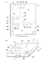
- FIG. 1 shows an example of the cartridge in this embodiment.
- the cartridge of this example is a disposable type cartridge that can be attached to an analyzer (not shown).
- FIG. 1A is a plan view of the cartridge
- FIG. 1B is a perspective view of the cartridge. 1 (A) and 1 (B), the same parts are denoted by the same reference numerals. Both figures are schematic diagrams for ease of understanding, and the size, ratio, and the like of each component are not limited to this and may be different.
- the cartridge 1 has a lower substrate 3, an upper substrate 2, and a connector 7, and a connector is provided on one side of a laminate in which the upper substrate 2 is laminated on the lower substrate 3. 7 is arranged. A wiring pattern (not shown) is formed on the lower substrate 3.
- the upper substrate 2 has five through holes.
- Five liquid tanks are formed by sealing the bottoms of the five through holes with the lower substrate 3.
- the five liquid tanks are a sample introduction part 41, a drain 45, a drain 55, a drain 58, and a drain 65, respectively.
- Four concave portions are formed on the bottom surface of the upper substrate 2.
- Two liquid tanks are formed by sealing the opening surfaces of the two recesses with the lower substrate 3 among the four recesses.
- the two liquid tanks are a reagent tank 51 and a dilution tank 59, respectively.
- the reagent tank 51 is filled with an analysis reagent.
- a stirring bar (not shown) is enclosed.
- the electrodes 61 and 62 connected to the wirings in the wiring pattern are respectively disposed in the gaps in which the opening surfaces of the remaining two concave portions are sealed by the lower substrate 3.
- gap is an electrode arrangement
- 61 and 62 are the said electrodes and also the said electrode arrangement
- a plurality of grooves are formed on the bottom surface of the upper substrate 2. The opening surfaces of the plurality of grooves are sealed by the lower substrate 3 so that the seven liquid tanks formed by the five through holes and the two concave portions and the two electrode arrangement portions communicate with each other. A road is formed.
- the sample introduction part 41 communicates with the drain 45 through a sample introduction flow path 42, a branch part 43, and an overflow flow path 44 in this order.
- the sample introduction part 41 communicates with the dilution tank 59 from the branch part 43 via the sample measurement channel 46.
- the opening of the sample introduction part 41 is an introduction port for introducing a sample to be analyzed into the cartridge.
- An orifice 47 having a narrow channel cross-sectional area is formed at the end of the sample measuring channel 46 on the dilution tank 59 side.
- the cartridge 1 can measure the sample and introduce it into the dilution tank 59 as follows, for example. First, after the sample is introduced into the sample introduction part 41, air is sucked by a decompression pump or the like (not shown) connected to the drain 45, and the inside of the flow path communicating with the drain 45 is decompressed, so that the sample introduction part A sample is introduced from 41. Due to the suction, the sample exceeding the volume of the sample measuring channel 46 between the branching portion 43 and the orifice 47 flows out into the overflow channel 44. Subsequently, the drain 45 is closed and air is discharged by a pressurizing pump or the like (not shown) connected to the sample introduction unit 41 to pressurize the inside of the flow path communicating with the sample introduction unit 41. As a result, a sample corresponding to the volume of the sample measuring channel 46 is introduced into the dilution tank 59. For this reason, the introduction amount is set, for example, to the volume of the sample measurement channel 46, and the introduction of the measurement becomes possible.
- the reagent tank 51 communicates with the drain 55 through a reagent introduction channel 52, a branching portion 53, and an overflow channel 54 in this order.
- the reagent tank 51 also communicates with the dilution tank 59 from the branch portion 53 via a reagent measuring channel 56.
- an analysis reagent (not shown) is sealed.
- the reagent metering channel 56 branches between an end on the dilution tank side and the dilution tank 59, and the drain 58 is formed at the branch end.
- the reagent tank 51, the reagent introduction flow path 52, the branching section 53, the overflow flow path 54, the drain 55, the reagent metering flow path 56, the drain 58, and the dilution tank 59 constitute the dilution section 5.
- a taper portion 57 is formed at the dilution tank side portion of the reagent measuring channel 56.
- the analysis reagent can be weighed and introduced into the dilution tank 59 as follows. First, the drain 55 and the drain 65 are closed, the drain 58 is opened, and air is discharged by a pressure pump (not shown) connected to the reagent tank 51 to communicate with the reagent tank 51. Pressurize the inside of the flow path. As a result, the reagent measuring channel 56 is filled with the analysis reagent. Further, the drain 58 is closed, the drain 65 is opened, air is discharged by a pressure pump (not shown) or the like connected to the drain 55, and the inside of the flow path communicating with the drain 55 is pressurized.
- a pressure pump not shown
- an analysis reagent corresponding to the volume of the reagent metering channel 56 is introduced into the dilution tank 59.
- the introduction amount is set, for example, to the volume of the sample measurement channel 56, and the introduction of the measurement becomes possible.
- the sample is introduced into the dilution tank 59.
- the sample and the analysis reagent can be mixed by rotating the stirring bar (not shown) in the dilution tank 59 with a magnetic stirrer (not shown).
- a surfactant may be added to the analysis reagent so that hemolysis can be performed.
- a pore 63 is formed on the flow path connecting the dilution tank 59 and the drain 65.
- the electrode arrangement portions 61 and 62 (two recesses) are formed in the flow paths at both ends of the pore 63.
- the electrodes 61 and 62 connected to an electric resistance detector (not shown) via the electric wires are arranged in the electrode arrangement portions 61 and 62 (recesses), respectively.
- a flow rate measurement channel 64 is formed on the drain 65 side through the pore 63 and the two electrodes 61 and 62.
- the analysis unit 6 is configured by the electrodes 61 and 62, the pores 63, the flow rate measurement channel 64 and the drain 65.
- the length and width of the upper substrate 2 are not particularly limited, and are, for example, in the range of 10 to 200 mm, preferably in the range of 20 to 100 mm.
- the thickness of the upper substrate 2 is not particularly limited, and is, for example, in the range of 0.1 to 10 mm, and preferably in the range of 1 to 5 mm.
- the length and width of the lower substrate 3 are not particularly limited, and are the same as the length and width of the upper substrate 2, for example.
- the thickness of the lower substrate 3 is not particularly limited, and is, for example, in the range of 0.1 to 10 mm, and preferably in the range of 1 to 5 mm.
- the material of the upper substrate 2 and the lower substrate 3 is not particularly limited as long as it does not interfere with the measurement of the absorbance.
- the material of the upper substrate 2 and the lower substrate 3 for example, those formed of glass, polymer material or the like can be used.
- the glass material is not particularly limited, and examples thereof include synthetic quartz glass, fused silica, and borosilicate glass.
- the polymer material is not particularly limited.
- acrylic resin such as polymethyl methacrylate (PMMA), cycloolefin polymer (COP), polycarbonate (PC), polydimethylsiloxane (PDMS), polystyrene (PS), polylactic acid (PLA), epoxy resin, polyethylene (PE), polytetrafluoroethylene (PTFE), polyether ether ketone (PEEK) and the like.
- the lower substrate 3 is formed by laminating a plurality of substrates made of the material. A wiring pattern made of copper foil or the like is formed between the plurality of substrates.
- the diameter and depth of the sample introduction part 41 are not particularly limited.
- the diameter is in the range of 0.1 to 10 mm, and the depth is in the range of 0.1 to 10 mm.
- the diameter is in the range of 1-5 mm and the depth is in the range of 1-5 mm.
- the diameter and depth of the reagent tank 51 are not particularly limited.
- the diameter is in the range of 0.5 to 50 mm, and the depth is in the range of 0.1 to 10 mm.
- the diameter is in the range of 1-20 mm and the depth is in the range of 1-5 mm.
- the diameter and depth of the dilution tank 59 are not particularly limited.
- the diameter is in the range of 0.5 to 50 mm, and the depth is in the range of 0.1 to 10 mm.
- the diameter is in the range of 1-10 mm and the depth is in the range of 1-5 mm.
- the diameters and depths of the drains 45, 55, 58, and 65 are not particularly limited.
- the diameter is in the range of 0.1 to 10 mm, and the depth is 0.1.
- the diameter is in the range of 1 to 10 mm, preferably the diameter is in the range of 1 to 5 mm, and the depth is in the range of 1 to 5 mm.
- the sample introduction part 41, the reagent tank 51, the dilution tank 59 and the liquid tanks of the drains 45, 55, 58 and 65 are cylindrical, but the present invention is limited to this.
- the shape of each liquid tank is not particularly limited, and examples thereof include a cylindrical shape, a quadrangular prism shape, a quadrangular pyramid shape, and a conical shape.
- the shapes of the liquid tanks may all be the same or different, and are not particularly limited.
- the width and depth of the reagent metering channel 56 are not particularly limited, and the width is, for example, in the range of 0.1 to 10 mm at the maximum portion of the cross-sectional area. Is in the range of 0.1 to 10 mm, preferably the width is 0.5 to 5 mm and the depth is 0.1 to 5 mm.
- the width and depth of the orifice 47 are not particularly limited.
- the width is in the range of 1 to 200 ⁇ m, and the depth is in the range of 0.1 to 10 mm.
- the width is 10 to 100 ⁇ m and the depth is 0.1 to 5 mm.
- the width, depth and length of the pore 63 are as described above.
- the width and depth of the channels other than the reagent metering channel 56, the orifice 47 and the pore 63 are not particularly limited.
- the width is in the range of 10 to 1000 ⁇ m, Is in the range of 0.1 to 10 mm, preferably the width is 100 to 500 ⁇ m and the depth is 0.1 to 5 mm.
- the maximum thickness of the entire cartridge is the total thickness of the upper substrate 2 and the lower substrate 3.
- the thicknesses of the upper substrate 2 and the lower substrate 3 are as described above.
- the manufacturing method of the cartridge 1 is not particularly limited, and for example, a conventionally known method can be adopted.
- the cartridge 1 is mounted on an analyzer (not shown) via the connector 7.
- human whole blood is introduced from the sample introduction unit 41 in the same manner as described above.
- a volume of human whole blood corresponding to the volume of the sample measuring channel 46 is weighed and introduced into the dilution tank 59.
- an amount of the analysis reagent corresponding to the volume of the reagent metering channel 56 is weighed and introduced into the dilution tank 59.
- the introduced sample and the analysis reagent are mixed in the dilution tank 59, the stirrer (not shown) is rotated by the magnetic stirrer (not shown), and the white blood cells and red blood cells in the sample are stirred. And the analysis reagent are reacted.
- a voltage is applied between the electrodes 61 and 62, air is sucked by a decompression pump or the like (not shown) connected to the drain 65, and the inside of the flow path communicating with the drain 65 is decompressed.
- a solution obtained by mixing the sample and the analysis reagent is allowed to pass through the pore 63 and further flow out to the flow rate measurement channel 64.
- a pulse (impedance change) generated when the liquid mixture passes through the pores 63 is measured by an electric resistance detector (not shown), and a histogram with the magnitude and frequency of the pulse as two axes is displayed. create.
- the white blood cells are classified into three types according to size from the inflection state of the created histogram, and the pulse frequency for each classification is integrated.
- the accumulated pulse frequency is divided by the flow rate flowing out into the flow rate measurement channel 64, and the ratio of the three classified white blood cells in the sample is calculated.
- the three types of white blood cells are lymphocytes, monocytes, and granulocytes in the order of smaller pulses.
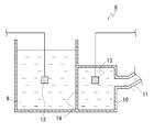
- FIG. 2 shows an example of a leukocyte analyzer used in the analysis method of this embodiment.
- FIG. 2 is a sectional view of the leukocyte analyzer. This figure is a schematic diagram for easy understanding, and the size and ratio of each component are not limited to this and may be different.
- the leukocyte analyzer 8 is composed of two tanks, a main tank 9 and a sub tank 10, two electrodes, a suction part 11, an electrode 12 and an electrode 13, and an analysis part (not shown).
- the main tank 9 and the sub tank 10 are arranged separated by a partition wall.
- the partition wall is formed with a through hole serving as a pore 14 and communicates the inside of the two tanks.
- the main tank 9 has an upper surface opened.
- the sub tank 10 has a through hole formed on a side surface different from the partition wall, and the suction part 11 communicates with the through tank through the through hole.
- a pump (not shown) is disposed at the other end of the suction part 11.
- the electrodes 12 and 13 are disposed in the main tank 9 and the sub tank 10, respectively.
- the electrodes 12 and 13 are disposed at the ends of electric wires (only part of which are shown) connected to the analysis unit (not shown).
- the same material as the upper substrate of the cartridge described above can be used.
- the shapes of the main tank 9 and the sub tank 10 are not particularly limited, and examples thereof include a rectangular parallelepiped and a cylindrical shape.
- the shapes of the main tank 9 and the sub tank 10 may be exactly the same or different, and are not particularly limited. Further, as described above, for example, the upper surface of the main tank 9 may be opened.
- the pores 14 have, for example, a diameter in the range of 1 to 500 ⁇ m and a length in the range of 1 to 200 ⁇ m, and preferably a diameter in the range of 10 to 100 ⁇ m and a length of 10
- the through hole is in the range of ⁇ 100 ⁇ m.
- the diameter is, for example, the diameter of a cross section perpendicular to the penetration direction of the pore 14, and the length is the length of the penetration direction of the pore 14, and the main tank 9 and the sub tank 10 is the thickness of the partition wall.
- the material of the suction part 11 is not particularly limited, and for example, the same material as the two tanks described above can be used.
- the shape of the suction part 11 is not particularly limited and is, for example, a cylindrical shape.
- the manufacturing method of the leukocyte analyzer 8 of this example is not particularly limited, and for example, a conventionally known method may be appropriately used.
- the analysis reagent of the present invention is injected into the main tank 9 and the sub tank 10.
- human whole blood is added to the main tank 9 and mixed for 30 seconds.
- a voltage is applied between the two electrodes, suction is performed by the pump connected to the suction unit 11, and the inside of the auxiliary tank 10 is decompressed.
- the liquid mixture passes through the pores 14 and is moved from the main tank 9 to the sub tank 10.
- a pulse (impedance change) generated when the liquid mixture passes through the pores 14 is measured using the analysis unit (not shown).
- a histogram is created, white blood cells are classified and counted, and the ratio of the classified white blood cells is calculated.
- FIG. 7 shows an example of a leukocyte analyzer used in the analysis method of this embodiment.
- FIG. 7 is a sectional view of the leukocyte analyzer. This figure is a schematic diagram for easy understanding, and the size and ratio of each component are not limited to this and may be different.
- the leukocyte analyzer 88 includes a main tank section 90, a sub tank section 100, a stirring section 160, a suction section 11, and electrodes 12 and 13.
- the stirring unit 160 includes a substrate unit 16 and a stirring pipe 18.
- the suction part 11 includes a suction pipe 19 and a syringe (not shown).
- the main tank portion 90 is formed of a two-layer body in which two substrates, a substrate 91a and a substrate 91b, are stacked in parallel, and includes a void portion 9 that is open at the top and can store a liquid. This void portion becomes the main tank 9.
- a through hole 22 a and a through hole 22 c communicating with the inside of the main tank 9 are formed in the substrate 91 a and the substrate 91 b which are side surfaces of the main tank 9, respectively.
- One end of the stirring pipe 18 is connected to the through hole 22c.
- An electrode 12 is disposed in the main tank 9. The electrode 12 is connected to a voltage device via an electric wire (not shown).
- the sub tank portion 100 is formed of a two-layer body in which two substrates of a substrate 101a and a substrate 101b are stacked in parallel, and is disposed adjacent to the main tank portion 90.
- the sub tank portion 100 includes a gap portion 10 into which a liquid can be introduced. This void portion becomes the auxiliary tank 10.
- three through holes communicating with the inside of the sub tank 10 are formed in the vertical direction in the substrate 101 a which is a side surface of the sub tank 10.
- the middle through hole 22b is connected to the through hole 22a of the adjacent main tank 90. Thereby, the inside of the main tank part 90 communicates with the inside of the sub tank part 100.
- the connecting portion between the through hole 22b of the sub tank part 100 and the through hole 22a of the main tank part 90 becomes the pore 14.
- the upper through hole 21a and the lower through hole 21b serve as an inlet 21a and an inlet 21b, respectively.
- One end of a suction pipe (not shown) is connected to the introduction port 21a, and the syringe (not shown) is connected to the other end of the suction pipe.
- the introduction ports 21a and 21b may be openable and closable, or may be connected to a solution tank for discharging the solution introduced into the sub tank unit 100.
- a gap communicating from the inlet 21 a to the through hole 22 b can be used as the quantitative unit 15, for example.
- An electrode 13 is disposed in the auxiliary tank 10. The electrode 13 is connected to the voltage device via an electric wire (not shown).
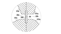
- FIG. 8 shows another example of the pore 14 portion of the leukocyte analyzer 88.
- FIG. 8 is an enlarged view showing another example of a portion surrounded by a dotted line in FIG.
- an elastic body 840 having a through hole may be disposed in a region where the through hole 22a of the main tank portion 90 and the through hole 22b of the sub tank portion 100 communicate with each other.
- the through hole formed in the elastic body 840 becomes the pore 84.
- the material of the elastic body 840 is not particularly limited, and examples thereof include silicone rubber.
- the substrate portion 16 is formed of a two-layer body in which two substrates, a substrate 161a and a substrate 161b, are stacked in parallel, and includes a gap portion 17 that can contain a liquid therein. This void portion becomes the stirring tank 17.
- two through holes 22 d and 22 e communicating with the inside of the stirring tank 17 are formed in the vertical direction on the substrate 161 b which is a side surface of the stirring tank 17.
- One end of the suction pipe 19 is connected to the through hole 22d, and the syringe (not shown) is connected to the other end of the suction pipe 19.
- One end of the stirring pipe 18 is connected to the through hole 22e, and the other end of the stirring pipe 18 is connected to the through hole 22c of the main tank portion 90 as described above.
- the stirring pipe 18 communicates the inside of the substrate portion 16 and the main tank portion 90.
- the material of the substrates 91a, 91b, 101a, 101b, 161a, and 161b is not particularly limited, and examples thereof include the glass and polymer materials described above.
- the size of the main tank portion 90 is not particularly limited.
- the height is in the range of 3 to 100 mm
- the width is in the range of 3 to 50 mm
- the thickness is in the range of 3 to 50 mm.
- the volume of the main tank 9 is not particularly limited, but is, for example, in the range of 10 to 5000 ⁇ L, and preferably 100 to 1000 ⁇ L.
- the size of the sub-tank portion 100 is not particularly limited.
- the height is in the range of 10 to 200 mm
- the width is in the range of 3 to 50 mm
- the thickness is in the range of 3 to 50 mm.
- the volume of the sub-tank 10 is not particularly limited, but is, for example, in the range of 10 to 5000 ⁇ L, preferably 100 to 1000 ⁇ L.
- gap part from the said through-hole 22b to the said inlet 21a can be used as the fixed_quantity
- the size of the substrate portion 16 is not particularly limited, and for example, the height is in the range of 3 to 200 mm, the width is in the range of 3 to 50 mm, and the thickness is in the range of 3 to 50 mm.
- the volume of the stirring tank 17 is not particularly limited, but is preferably 100 to 1000 ⁇ L, for example.
- the size of the pores 14 is, for example, a diameter in the range of 1 to 500 ⁇ m, a length in the range of 1 to 200 ⁇ m, and preferably a diameter in the range of 10 to 200 ⁇ m. Is in the range of 10 to 100 ⁇ m.
- the diameter is, for example, the diameter of a cross section perpendicular to the penetration direction of the pore 14, and the length is the total thickness of the substrate 91b and the substrate 101a in the pore 14 portion.
- the size of the pores 84 is the same, for example.
- the diameter of the inlets 21a and 21b is, for example, in the range of 0.1 to 2 mm, and preferably in the range of 0.5 to 1 mm.
- the diameter of the through holes 22c, 22d and 22e is, for example, in the range of 0.1 to 2 mm, and preferably in the range of 0.5 to 1 mm.
- the material of the stirring pipe 18 and the suction pipe 19 is not particularly limited, and for example, stainless steel can be used.
- the stainless steel is not particularly limited, and examples thereof include SUS.
- the shapes of the stirring pipe 18 and the suction pipe 19 are not particularly limited, and are, for example, cylindrical.
- the inner diameters of the stirring pipe and the suction pipe are, for example, in the range of 1 to 500 ⁇ m, and preferably in the range of 10 to 200 ⁇ m.
- the lengths of the stirring pipe and the suction pipe are not particularly limited, but are, for example, in the range of 1 to 500 mm, and preferably in the range of 10 to 200 mm.
- the manufacturing method of the leukocyte analyzer 88 of this example is not particularly limited, and for example, a conventionally known method may be used as appropriate.
- human whole blood is diluted with physiological saline to prepare the sample.
- physiological saline is introduced from the inlet 21b, filled up to the top of the electrode 13 in the auxiliary tank 10, and the inlet 21b is closed.
- the sample is injected into the main tank 9.
- Each tank and pipe communicating with the main tank 9 are decompressed (sucked) by the syringe (not shown) connected to the suction pipe 19. Thereby, the sample in the main tank 9 is introduced into the stirring tank 17.
- the analysis reagent of the present invention is injected into the main tank 9.
- a tank and a pipe communicating with the main tank 9 are pressurized (discharged) by the syringe.
- the sample in the stirring tank 17 is reintroduced into the main tank 9. Furthermore, the pressure reduction and pressurization of the tank and pipe communicating with the main tank 9 are alternately repeated by the syringe. Thereby, the sample and the analysis reagent are mixed. After completion of the mixing, the mixed solution of the sample and the analysis reagent is left in the main tank 9. A voltage is applied between the electrodes 12 and 13, and suction is performed by a syringe (not shown) connected to the introduction port 21a, so that the sub tank 10 and the main tank 9 are decompressed. As a result, the liquid mixture passes through the pores 14 and is moved from the main tank 9 to the sub tank 10.
- a pulse (impedance change) generated when the sample passes through the pores 14 is measured using an analysis unit (not shown).
- a histogram is created, white blood cells are classified and counted, and the ratio of the classified white blood cells is calculated.
- the said cavity part 10 of the said subtank part 100 when the space
- Example 1 human blood with a hematocrit value of 31.4% was used as a sample, and white blood cells were measured by the following procedure.
- the leukocyte analyzer 8 shown in FIG. 2 was used for the measurement of leukocytes in this example.
- the pore 14 is a through-hole having a diameter of 50 ⁇ m and a length of 60 ⁇ m.
- analytical reagents having the compositions shown in Table 1 below were prepared.
- the conductivity of the analysis reagent was adjusted to 11.33 mS / cm using sodium chloride.
- the analytical reagent was placed in the main tank 9, and the auxiliary tank 10 was filled with the analytical reagent.
- 100 ⁇ L of whole blood was added to the main tank 9 and stirred to react with the analysis reagent.
- the dilution rate of whole blood was 25 times. That is, in this example, leukocytes were analyzed under conditions where the sample dilution rate was low.
- between the electrodes 12 and 13 installed in the main tank 9 and the auxiliary tank 10 is applied at 5 V, and the pump of the suction unit 11 is used. Aspiration was performed at a flow rate of 14 ⁇ L / 30 seconds for 10 seconds.
- a pulse generated when the mixed solution of the sample and the analysis reagent passes through the pores 14 was measured using a self-made electric detector (not shown).
- a histogram showing the particle size distribution of white blood cells was prepared with the obtained pulse height as the horizontal axis and the number of pulses as the vertical axis. From the height of the pulse, leukocytes were classified into three sizes: small size (lymphocytes), medium size (monocytes), and large size (granulocytes). In the classification, the small size is the first peak portion that appears after the electrical noise peak at the left end of the histogram, and the large size is the second peak portion counted from the electrical noise peak. To the right end of the histogram, and the middle size is the valley portion that appears between the small size mountain and the large size mountain. The number of pulses of the three sizes was integrated, and the ratio (n) to the total number of pulses was calculated.
- the ratio (m) of leukocytes of each size was calculated in the same manner as described above except that the pulse obtained for 10 seconds after the start of the reaction was measured for 10 seconds. Using the following formula (1), the change rate k (%) of each ratio at the reaction time of 30 seconds and 60 seconds was calculated.
- k (%) m / n ⁇ 100 (1)
- m ratio of white blood cells of each size when the reaction time is 60 seconds (%)
- n ratio of white blood cells of each size when the reaction time is 30 seconds (%)
- Example 2 leukocytes were measured in the same manner as in Example 1 except that human whole blood having a hematocrit value of 39.2% was used as the sample, and the ratio and the rate of change were calculated.
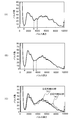
- FIG. 3 (A) is a histogram showing the particle size distribution of leukocytes when the reaction time is 30 seconds
- FIG. 3 (B) is a histogram showing the particle size distribution of leukocytes when the reaction time is 60 seconds.
- FIG. 3C is a histogram in which the two histograms are superimposed.
- a histogram showing the particle size distribution of leukocytes in Example 2 is shown in FIG. As in Example 1, FIG.
- FIG. 4 (A) is a histogram showing the particle size distribution of leukocytes when the reaction time is 30 seconds
- FIG. 4 (B) is the leukocytes when the reaction time is 60 seconds
- FIG. 4C is a histogram in which the two histograms are overlaid. 3C and 4C, the solid line in (a) is a histogram when the reaction time is 30 seconds, and the solid line in (b) is a histogram when the reaction time is 60 seconds. It is.
- the horizontal axis is the pulse height
- the vertical axis is the number of pulses.
- a white blood cell having a pulse height in the range ab is defined as the small size (lymphocyte), b
- the leukocytes in the -c range were the medium size (monocytes), and the leukocytes in the range c or more (on the right side of c) were the large sizes (granulocytes).
- the difference in histogram due to reaction time is small in both examples, and as shown in Table 2, the rate of change indicating the difference due to reaction time is In both examples, it was almost 100%.
- the analysis reagent containing sucrose monolaurate was used, the difference in the measurement results depending on the reaction time between the sample and the analysis reagent was small, and leukocytes could be measured stably.
- whole blood having different hematocrit values was used. In both examples, the results as described above were obtained, so that the influence of the hematocrit values was avoided and the leukocytes were stabilized. I found that I can measure.
- Example 1 leukocytes were measured in the same manner as in Example 1 except that the analysis reagent obtained by removing only sucrose monolaurate from the analysis reagent of Example 1 was used, and the ratio and the rate of change were calculated. .
- Comparative Example 2 leukocytes were measured in the same manner as in Comparative Example 1 except that human blood having a hematocrit value of 39.2% was used as the sample, and the ratio and the rate of change were calculated.
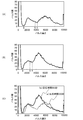
- FIG. 5A is a histogram showing the particle size distribution of leukocytes when the reaction time is 30 seconds
- FIG. 5B is a histogram showing the particle size distribution of leukocytes when the reaction time is 60 seconds.
- FIG. 5C shows a histogram in which the two histograms are superimposed.
- 6 (A) is a histogram showing the particle size distribution of white blood cells when the reaction time is 30 seconds
- FIG. 6 (B) is a white blood cell when the reaction time is 60 seconds
- 6C is a histogram in which the two histograms are overlaid.
- 5 (C) and 6 (C) the solid line (a) is a histogram when the reaction time is 30 seconds
- the solid line (b) is a histogram when the reaction time is 60 seconds. It is. 5 and 6, the horizontal axis represents the pulse height, and the vertical axis represents the number of pulses. In the histograms of FIGS.
- leukocytes having a pulse height in the range ab are classified into the small size (lymphoid).
- Spheres), leukocytes in the bc range were the medium size (monocytes), and leukocytes in the range of c and above (right side of c) were the large size (granulocytes).
- Comparative Example 1 As shown in FIG. 5 (C), the difference in histogram due to the reaction time between the sample and the analysis reagent is large, and as shown in Table 3, the rate of change is 69.2 to 197.8%. Variations were observed and leukocytes could not be analyzed stably.
- Comparative Example 2 as shown in FIG. 6C, the difference in histogram due to the reaction time between the sample and the analysis reagent is small as compared to Comparative Example 1, and the change rate is 89 as shown in Table 3 above. The variation was as small as 0.0 to 102.0%, and leukocytes could be stably analyzed.
- Comparative Example 1 and Comparative Example 2 using an analysis reagent that does not contain sucrose monolaurate the measurement results varied when the hematocrit values of the samples were different. Thus, the leukocytes were stably analyzed. could not.
- Example 3 leukocytes were measured by the following procedure using an analysis reagent to which an additive reagent shown in Table 4 below was added.
- a leukocyte analyzer 88 shown in FIG. 7 was used.
- the region including the pores is as shown in FIG.
- the volume of the main tank 9 is about 700 ⁇ L
- the volume of the auxiliary tank 10 is about 100 ⁇ L
- the volume of the quantification unit 15 is about 300 ⁇ L
- the stirring The volume of the tank 17 was about 400 ⁇ L.
- the electrode 8 was a through-hole having a diameter of 100 ⁇ m and a length of 100 ⁇ m.
- the electrodes 12 and 13 were made of platinum having a diameter of 1 ⁇ m.
- a voltage of 30 V was applied between the electrodes 12 and 13 using a voltage device.
- the pulse (impedance change) generated when the sample passed through the pore 84 was measured using an amplifier set to 30 V and 5 gain.
- human whole blood having a hematocrit value of 41.6% was used.
- the human whole blood was diluted 100-fold with physiological saline (0.9 w / v%, manufactured by Nacalai Tesque) to prepare a diluted sample.
- Example Additive reagent name Manufacturer name Example 3-1 Sucrose laurate Example 3-2 produced by Dojindo Laboratories Co., Ltd.
- Example 3-2 Sucrose monolaurate
- Example 3-3 produced by Dojindo Laboratories Co., Ltd.
- Sucrose monocaprate Example 3-4 produced by Dojindo Laboratories Co., Ltd.
- sucrose laurate added to the analysis reagent of Example 3-1 contains about 80 to 90% by volume of sucrose monolaurate (monoester), and sucrose dilaurate or sucrose trilaurate (diester or The mixture contained about 10 to 20% by volume of the triester).
- the sample and the analysis reagent were mixed.
- This mixed solution was allowed to stand in the main tank 9 for 1 minute.
- the concentration (final concentration) of each additive reagent in the mixed solution was 0.03 w / v%, respectively.
- a voltage was applied between the electrodes 12 and 13, the liquid was discharged by the syringe, and 300 ⁇ L of the mixed solution was moved from the main tank 9 to the sub tank 10 at a speed of about 2.8 ⁇ L / second.
- a pulse (impedance change) generated when the sample passed through the pore 84 was measured using a self-made electric detector (not shown).
- a histogram showing the particle size distribution of white blood cells was prepared by moving the pulse data at 7 points, using the moving average pulse height as the horizontal axis, and the moving average number of pulses as the vertical axis. From the height of the pulse, leukocytes were classified into three sizes: small size (lymphocytes), medium size (monocytes), and large size (granulocytes). In the classification, the small size is the first peak portion that appears after the electrical noise peak at the left end of the histogram, and the large size is the second peak portion counted from the electrical noise peak. To the right end of the histogram, and the middle size is a valley portion that appears between the small size mountain and the large size mountain. Each of the three sizes of pulses was integrated, and the ratio to the total number of pulses was calculated.
- FIGS. 9 and 10 and Table 6 below show the results of leukocyte analysis using each analysis reagent to which the additive reagents listed in Table 4 above were added.
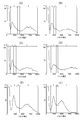
- 9A to 9C are histograms showing the particle size distribution of leukocytes by analysis using the analysis reagents of the comparative examples.
- 9A is Comparative Example 3-1 (basic reagent)
- FIG. 9B is Comparative Example 3-2 (analysis reagent added with lauryltrimethylammonium chloride)
- FIG. 9C is Comparative Example 3-3 (polyester). It is a histogram which shows the analysis result using the analysis reagent of oxyethylene lauryl ether addition analysis reagent.
- FIGS. 9A is Comparative Example 3-1 (basic reagent)
- FIG. 9B is Comparative Example 3-2 (analysis reagent added with lauryltrimethylammonium chloride)
- FIG. 9C is Comparative Example 3-3 (polyester). It is a histogram which shows the analysis result using
- 10A to 10D are histograms showing the particle size distribution of leukocytes by analysis using the analysis reagents of the respective examples.
- 10A is Example 3-1 (analytical reagent with sucrose laurate added)
- FIG. 10B is Example 3-2 (analytical reagent with sucrose monolaurate added)
- FIG. 10C is Example 3.
- -3 analysis reagent with sucrose monocaprate addition
- FIG. 10 (D) is a histogram showing the analysis results using the analysis reagent of Example 3-4 (analysis reagent with dodecyl maltoside addition).
- 9 and 10 the horizontal axis represents the pulse height, and the vertical axis represents the number of pulses.
- the white blood cells having a pulse height of area 2 are set to the small size (lymphocytes), the white blood cells of area 3 are set to the medium size (monocytes), and the white blood cells of area 4 are set to the large size (granulocytes).
- Area 1 is a blood component (noise) other than the white blood cells, and the main component is, for example, a lysate of red blood cells.
- Table 6 below shows the pulse range, the number of pulses, and the ratio of each area by the analysis using each analysis reagent.
- the basic reagent to which no nonionic surfactant is added in Comparative Example 3-1 has a small valley between the area 1 (noise) and the area 2 (lymphocytes).
- the separation accuracy of the area 1 (noise) and the area 2 (lymphocytes) was low.
- the analysis reagent of Comparative Example 3-2 to which the lauryltrimethylammonium chloride was added had a small valley between the area 1 (noise) and the area 2 (lymphocytes),
- the peak of area 4 (granulocyte) was smaller than that of the basic reagent.
- Example 3 to which a nonionic surfactant of sucrose laurate, sucrose monolaurate, sucrose monocaprate and dodecyl maltoside was added was used.
- the valley between the area 1 (noise) and the area 2 (lymphocytes) is larger than that of the basic reagent of the comparative example 3-1, and the area 2 (lymphocytes) ) Peak did not decrease, and the peak of area 4 (granulocyte) became clear. That is, by adding the nonionic surfactant, the separation accuracy of the noise and the lymphocytes was improved, and the separation accuracy of the granulocytes was improved.
- Example 4 In this example, the measurement was performed except that the final concentration of the lauryltrimethylammonium chloride in the basic reagent was 12.3 mmol / L, and each sucrose laurate was added to each of the basic reagents in Table 5 above. In the same manner as in Example 3, leukocytes were measured.
- the addition concentration of the sucrose laurate in the analysis reagent of this example is shown in Table 7 below. In Table 7 below, the final concentration is the sucrose laurate concentration in the mixed solution obtained by mixing the analysis reagent of this example and the sample.
- Example 4-1 0.0125 0.0038
- Example 4-2 0.025 0.0075
- Example 4-3 0.05 0.015
- Example 4-4 0.1 0.03
- FIG. 11 and Table 8 below show the analysis results of leukocytes in Comparative Example 4 and Examples 4-1 to 4-5.
- FIGS. 11A to 11F are histograms showing the particle size distribution of leukocytes by analysis using an analysis reagent to which the sucrose laurate is added at the predetermined concentration.
- 11A is Comparative Example 4 (basic reagent)
- FIG. 11B is Example 4-1
- FIG. 11C is Example 4-2
- FIG. 11D is Example 4-3
- FIG. 11 (E) is a histogram showing the results of analysis using the analysis reagent of Example 4-4
- FIG. 11 (F) is of Example 4-5. In the histograms of FIGS.
- the horizontal axis represents the pulse height
- the vertical axis represents the number of pulses.
- the white blood cells having a pulse height of area 2 are set to the small size (lymphocytes)
- the white blood cells of area 3 are set to the medium size (monocytes)
- the white blood cells of area 4 are set to the large size (granulocytes). It was.
- Area 1 is a blood component (noise) other than the white blood cells.
- Table 8 below shows the pulse range, the number of pulses, and the ratio of each area by the analysis using each analysis reagent.
- the analysis reagent of the present invention containing a nonionic surfactant having a sugar residue as a hydrophilic part and a fatty chain as a hydrophobic part, for example, when the dilution ratio of the sample is low Even when the flow rate of the sample at the time of analysis is slow, the leukocytes can be measured stably. Further, by using the analysis reagent of the present invention, for example, even in the case described above, it is possible to measure with high accuracy.
- the analysis method of the present invention can stably analyze leukocytes even when the dilution rate is low, such as ⁇ TAS, or under analysis conditions with a low flow rate.
- the present invention can be applied to all fields in which white blood cells are analyzed, such as clinical tests, biochemical tests, medical research, etc., and its use is not limited and can be applied to a wide range of fields.
Landscapes
- Life Sciences & Earth Sciences (AREA)
- Health & Medical Sciences (AREA)
- Immunology (AREA)
- Engineering & Computer Science (AREA)
- Cell Biology (AREA)
- Chemical & Material Sciences (AREA)
- Urology & Nephrology (AREA)
- Biomedical Technology (AREA)
- Molecular Biology (AREA)
- Hematology (AREA)
- Microbiology (AREA)
- Biotechnology (AREA)
- Tropical Medicine & Parasitology (AREA)
- Ecology (AREA)
- Food Science & Technology (AREA)
- Medicinal Chemistry (AREA)
- Physics & Mathematics (AREA)
- Analytical Chemistry (AREA)
- Biochemistry (AREA)
- General Health & Medical Sciences (AREA)
- General Physics & Mathematics (AREA)
- Pathology (AREA)
- Investigating Or Analysing Biological Materials (AREA)
Abstract
Description
前述のように、本発明の分析方法は、白血球および赤血球を含む試料と、白血球に反応する界面活性剤を含む分析試薬とを混合する混合工程と、前記試料と前記分析試薬との混合液を、細孔を通過させ、前記通過時に検出される信号を測定し、前記試料中の白血球を分類および計数する測定工程とを含む白血球の分析方法であって、前記分析試薬が、さらに、非イオン性界面活性剤を含み、前記非イオン性界面活性剤が、親水性部として糖残基を有し、疎水性部として脂肪鎖を有することを特徴とする。なお、本発明の分析方法において使用する前記分析試薬は、本発明の分析試薬に該当する。
前記混合工程では、前記試料と前記分析試薬とを混合し、前記試料中の前記白血球および前記赤血球を、前記分析試薬と反応させる。前記白血球に対する反応としては、例えば、白血球の細胞膜の溶解による裸核化、浸透圧変化による収縮または膨張等があげられる。また、本発明において、前記赤血球に対する反応としては、例えば、溶血、赤血球膜の溶解等があげられる。
前記測定工程では、前記試料と前記分析試薬との前記混合液を、細孔を通過させ、前記通過時に発生する信号を測定し、白血球を分類および計数する。なお、本発明は、例えば、前記試料と前記分析試薬との前記混合液について、前記試料中の細胞の大きさに関する情報および形態に関する情報の少なくとも一方を検出することで、白血球を分類および計数する方法ともいえる。これらの情報は、後述するシグナルとして検出できる。
以下に、μTASであるカートリッジを使用した、本発明の分析方法の一形態を説明する。まず、図1に、本形態における前記カートリッジの一例を示す。本例のカートリッジは、分析装置(図示せず)に装着可能な、ディスポーザブルタイプのカートリッジである。図1(A)は、前記カートリッジの平面図であり、図1(B)は、前記カートリッジの斜視図である。図1(A)および(B)において、同一部分には同一符号を付している。両図は、わかりやすくするための概略図であり、各構成要素の大きさや比率等は、これに制限されず、異なってよい。両図に示すように、前記カートリッジ1は、下基板3と上基板2とコネクタ7とを有し、前記下基板3の上に前記上基板2が積層された積層体の一側面に、コネクタ7が配置されている。前記下基板3には、配線パターン(図示せず)が形成されている。
つぎに、本発明の分析方法のその他の形態を説明する。まず、図2に、本形態の分析方法に使用する白血球分析装置の一例を示す。図2は、前記白血球分析装置の断面図である。同図は、わかりやすくするための概略図であり、各構成要素の大きさや比率等は、これに制限されず、異なってよい。
つぎに、本発明の分析方法のさらにその他の形態を説明する。まず、図7に、本形態の分析方法に使用する白血球分析装置の一例を示す。図7は、前記白血球分析装置の断面図である。同図は、わかりやすくするための概略図であり、各構成要素の大きさや比率等は、これに制限されず、異なってよい。
本例では、試料として、ヘマトクリット値が31.4%のヒト全血を用い、以下の手順により、白血球を測定した。なお、本例における白血球の測定には、前述の、図2に示す白血球分析装置8を用いた。前記白血球分析装置8において、前記細孔14は、直径50μm、長さ60μmの貫通孔である。
成分 配合濃度
ADA-緩衝液(pH7.4) 30mmol/L
塩化ラウリルトリメチルアンモニウム 0.75w/v%
塩化セチルトリメチルアンモニウム 0.1w/v%
サポニン 0.18w/v%
クエン酸ナトリウム 0.25w/v%
亜硝酸ナトリウム 0.05w/v%
スクロースモノラウレート 0.0125w/v%
m=反応時間を60秒としたときの各サイズの白血球の比率(%)
n=反応時間を30秒としたときの各サイズの白血球の比率(%)
本例では、前記試料として、ヘマトクリット値が39.2%のヒト全血を用いた以外は、実施例1と同様にして、白血球を測定し、前記比率および前記変化率を算出した。

本例では、前記実施例1の分析試薬からスクロースモノラウレートのみを除いた分析試薬を用いた以外は、実施例1と同様にして、白血球を測定し、前記比率および前記変化率を算出した。
本例では、前記試料として、ヘマトクリット値が39.2%のヒト全血を用いた以外は、比較例1と同様にして、白血球を測定し、前記比率および前記変化率を算出した。

本例では、下記表4に示す添加試薬を添加した分析試薬を用い、以下の手順により、白血球を測定した。なお、本例の測定では、図7に示す白血球分析装置88を用いた。前記白血球分析装置88において、細孔を含む領域は、図8に示すとおりである。なお、前記白血球分析装置88において、前記主槽9の容積は、約700μLであり、前記副槽10の容積は、約100μLであり、前記定量部15の容積は、約300μLであり、前記撹拌槽17の容積は、約400μLであった。また、図8に示す前記細孔84は、直径が、100μm、長さが、100μmの貫通孔であった。前記電極12および13は、直径1μmの白金を用いた。前記電極12および13間には、電圧器を用い、30Vの電圧を印加した。そして、前記試料が、前記細孔84の通過時に発生するパルス(インピーダンス変化)を、30V、5ゲインに設定したアンプを使用して測定した。また、血液試料として、ヘマトクリット値が41.6%のヒト全血を用いた。本例では、前記ヒト全血を、生理食塩水(0.9w/v%、ナカライテスク社製)で100倍希釈し、希釈試料を調製した。
例 添加試薬名 製造会社名
実施例3-1 スクロースラウレート 同仁化学研究所社製
実施例3-2 スクロースモノラウレート 同仁化学研究所社製
実施例3-3 スクロースモノカプレート 同仁化学研究所社製
実施例3-4 ドデシルマルトシド 同仁化学研究所社製
比較例3-1 未添加
比較例3-2 塩化ラウリルトリメチルアンモニウム ナカライテスク社製
比較例3-3 ポリオキシエチレンラウリルエーテル(30%溶液)
(商品名:Brig 35) ナカライテスク社製
成分 配合濃度 最終濃度
(mmol/L) (mmol/L)
リン酸緩衝液(pH7.5) 83 25
塩化ラウリルトリメチルアンモニウム 43 12.88
塩化セチルトリメチルアンモニウム 2 0.625
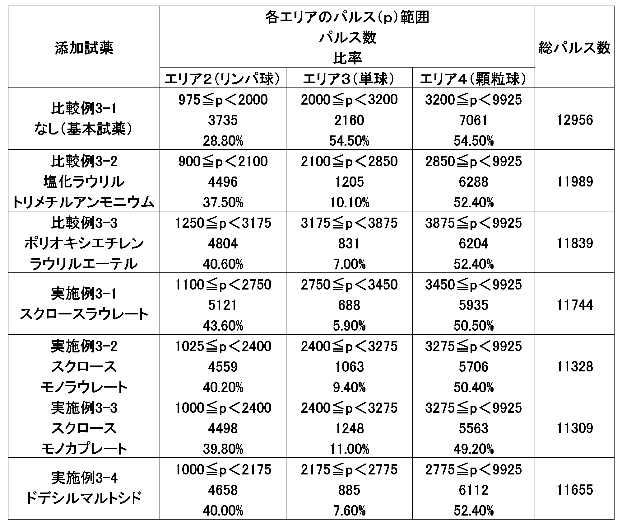
本例では、前記基本試薬中の前記塩化ラウリルトリメチルアンモニウムの最終濃度を12.3mmol/Lとし、前記スクロースラウレートを、前記表5の基本試薬に添加した各分析試薬を用いた以外は、実施例3と同様にして、白血球を測定した。なお、本例の分析試薬における、前記スクロースラウレートの添加濃度を、下記表7に示す。下記表7において、最終濃度は、本例の分析試薬と試料とを混合した混合液中の前記スクロースラウレート濃度である。
例 スクロースラウレート
添加濃度(w/v%) 最終濃度(w/v%)
比較例4(基本試薬) 0(未添加) 0(未添加)
実施例4-1 0.0125 0.0038
実施例4-2 0.025 0.0075
実施例4-3 0.05 0.015
実施例4-4 0.1 0.03
実施例4-5 0.2 0.06
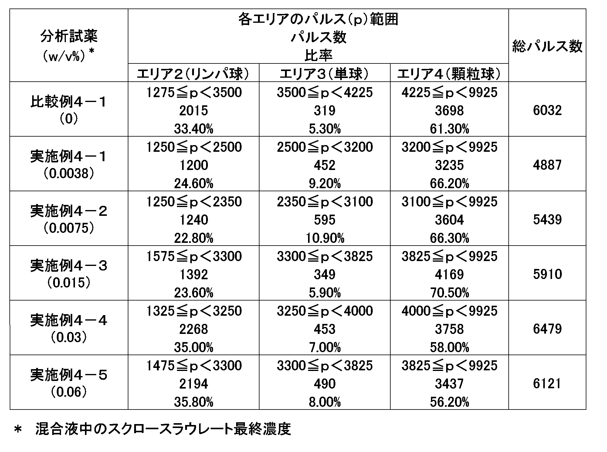
2 上基板
3 下基板
4 試料計量部
41 試料導入部
42 試料導入流路
43 分岐部
44 オーバーフロー流路
45、55、58、65 ドレイン
46 試料計量流路
47 オリフィス
5 希釈部
51 試薬槽
52 試薬導入流路
53 分岐部
54 オーバーフロー流路
56 試薬計量流路
57 テーパー部
59 希釈槽
6 分析部
61、62 電極、電極配置部
14、63、84 細孔
64 流量計測流路
7 コネクタ
8、88 白血球分析装置
9 主槽
10 副槽
11 吸引部
12、13 電極
15 定量部
16 基板部
17 撹拌槽
18 撹拌パイプ
19 吸引パイプ
21a、21b 貫通孔、導入口
22a、22b、22c、22d、22e 貫通孔
90 主槽部
100 副槽部
160 撹拌部
91a、91b、101a、101b、161a、161b 基板
840 弾性体
Claims (21)
- 白血球および赤血球を含む試料と、白血球に反応する界面活性剤を含む分析試薬とを混合する混合工程と、
前記試料と前記分析試薬との混合液を、細孔を通過させ、前記通過時に検出される信号を測定し、前記試料中の白血球を分類および計数する測定工程とを含む白血球の分析方法であって、
前記分析試薬が、さらに、非イオン性界面活性剤を含み、
前記非イオン性界面活性剤が、親水性部として糖残基を有し、疎水性部として脂肪鎖を有することを特徴とする白血球の分析方法。 - 前記糖残基が、二糖の残基である、請求の範囲1記載の白血球の分析方法。
- 前記脂肪鎖が、脂肪酸残基またはアルキル基である、請求の範囲1記載の白血球の分析方法。
- 前記非イオン性界面活性剤が、スクロースモノラウレート、スクロースラウレート、スクロースモノカプレートおよびドデシルマルトシドからなる群から選択される少なくとも一つである、請求の範囲1記載の白血球の分析方法。
- 前記試料と前記分析試薬との前記混合液中の前記非イオン性界面活性剤の濃度が、
0.001~5w/v%の範囲である、請求の範囲1記載の白血球の分析方法。 - 前記白血球に反応する界面活性剤が、第四級アンモニウム塩である、請求の範囲1記載の白血球の分析方法。
- 前記試料と前記分析試薬との前記混合液中の、前記白血球に反応する界面活性剤の濃度が、0.01~5w/v%の範囲である、請求の範囲1記載の白血球の分析方法。
- 前記分析試薬が、さらに、赤血球に反応する界面活性剤を含む、請求の範囲1記載の白血球の分析方法。
- 前記赤血球に反応する界面活性剤が、サポニンである、請求の範囲8記載の白血球の分析方法。
- 前記試料と前記分析試薬との前記混合液中の前記サポニンの濃度が、0.05~5w/v%の範囲である、請求の範囲9記載の白血球の分析方法。
- 前記混合工程において、前記試料(X)と前記分析試薬(Y)との混合体積比(X:Y)が、1:0.4~1:99の範囲である、請求の範囲1記載の白血球の分析方法。
- 前記測定工程において、前記白血球を、その体積により3種類に分類する請求の範囲1記載の白血球の分析方法。
- 前記測定工程において、
前記細孔を有するカートリッジを使用し、
前記混合液を、前記カートリッジ内の前記細孔を通過させる、請求の範囲1記載の分析方法。 - 前記カートリッジが、微小分析システムである、請求の範囲13記載の分析方法。
- 請求の範囲1記載の分析方法に使用するための、白血球に反応する界面活性剤を含む分析試薬であって、
さらに、非イオン性界面活性剤を含み、
前記非イオン性界面活性剤が、親水性部として糖残基を有し、疎水性部として脂肪鎖を有することを特徴とする分析試薬。 - 前記糖残基が、二糖である、請求の範囲15記載の分析試薬。
- 前記脂肪鎖が、脂肪酸残基またはアルキル基である、請求の範囲15記載の分析試薬。
- 前記非イオン性界面活性剤が、スクロースモノラウレート、スクロースラウレート、スクロースモノカプレートおよびドデシルマルトシドからなる群から選択される少なくとも一つである、請求の範囲15記載の分析試薬。
- 前記白血球に反応する界面活性剤が、第四級アンモニウム塩である、請求の範囲15記載の分析試薬。
- 前記分析試薬が、さらに、赤血球に反応する界面活性剤を含む、請求の範囲15記載の分析試薬。
- 前記赤血球に反応する界面活性剤が、サポニンである、請求の範囲20記載の分析試薬。
Priority Applications (4)
| Application Number | Priority Date | Filing Date | Title |
|---|---|---|---|
| US12/936,630 US20110027826A1 (en) | 2008-05-02 | 2009-04-30 | Leukocyte analysis method and analysis reagent for use in the method |
| CN2009801155558A CN102016576A (zh) | 2008-05-02 | 2009-04-30 | 白细胞的分析方法及其使用的分析试剂 |
| JP2010510163A JPWO2009133928A1 (ja) | 2008-05-02 | 2009-04-30 | 白血球の分析方法およびそれに使用する分析試薬 |
| EP09738865A EP2278331A4 (en) | 2008-05-02 | 2009-04-30 | LEUKOCYTE ANALYSIS METHOD AND ANALYSIS REAGENT FOR USE IN THE PROCESS |
Applications Claiming Priority (2)
| Application Number | Priority Date | Filing Date | Title |
|---|---|---|---|
| JP2008120248 | 2008-05-02 | ||
| JP2008-120248 | 2008-05-02 |
Publications (1)
| Publication Number | Publication Date |
|---|---|
| WO2009133928A1 true WO2009133928A1 (ja) | 2009-11-05 |
Family
ID=41255143
Family Applications (1)
| Application Number | Title | Priority Date | Filing Date |
|---|---|---|---|
| PCT/JP2009/058489 Ceased WO2009133928A1 (ja) | 2008-05-02 | 2009-04-30 | 白血球の分析方法およびそれに使用する分析試薬 |
Country Status (5)
| Country | Link |
|---|---|
| US (1) | US20110027826A1 (ja) |
| EP (1) | EP2278331A4 (ja) |
| JP (1) | JPWO2009133928A1 (ja) |
| CN (1) | CN102016576A (ja) |
| WO (1) | WO2009133928A1 (ja) |
Cited By (3)
| Publication number | Priority date | Publication date | Assignee | Title |
|---|---|---|---|---|
| JP2013205205A (ja) * | 2012-03-28 | 2013-10-07 | Nippon Koden Corp | 白血球分類用試薬およびこれを用いた白血球分類方法 |
| WO2014054172A1 (ja) * | 2012-10-05 | 2014-04-10 | 株式会社原田食品 | ゾル状低カロリー食品素材および包装容器体入ゾル状低カロリー食品素材およびそれらの製造方法 |
| JP2019528459A (ja) * | 2016-07-08 | 2019-10-10 | メディカ・コーポレーション | 自動顕微鏡血球分析 |
Families Citing this family (8)
| Publication number | Priority date | Publication date | Assignee | Title |
|---|---|---|---|---|
| JP6018237B2 (ja) * | 2014-02-14 | 2016-11-02 | アークレイ株式会社 | マイクロ流路を備えるチップの製造方法及びそれにより製造されるチップ |
| CA2941764C (en) | 2014-03-07 | 2023-10-24 | Dna Genotek Inc. | Composition and method for stabilizing nucleic acids in biological samples |
| US11478789B2 (en) | 2014-11-26 | 2022-10-25 | Medica Corporation | Automated microscopic cell analysis |
| US12005441B1 (en) | 2014-11-26 | 2024-06-11 | Medica Corporation | Automated microscopic cell analysis |
| US20170328924A1 (en) | 2014-11-26 | 2017-11-16 | Ronald Jones | Automated microscopic cell analysis |
| US10625259B1 (en) | 2014-11-26 | 2020-04-21 | Medica Corporation | Automated microscopic cell analysis |
| CN111912978B (zh) * | 2019-05-09 | 2025-05-20 | 深圳迈瑞动物医疗科技股份有限公司 | 白细胞分类计数的方法、装置和血液分析仪 |
| WO2023028835A1 (zh) * | 2021-08-31 | 2023-03-09 | 深圳迈瑞动物医疗科技股份有限公司 | 一种样本分析装置和样本分析方法 |
Citations (6)
| Publication number | Priority date | Publication date | Assignee | Title |
|---|---|---|---|---|
| JPS61502277A (ja) * | 1984-05-31 | 1986-10-09 | ク−ルタ−・エレクトロニクス・インコ−ポレ−テツド | 白血球を4種の集団に示差定量する方法およびこれに使用する試薬系 |
| JPH06273413A (ja) * | 1993-03-19 | 1994-09-30 | Toa Medical Electronics Co Ltd | 幼若細胞測定用試薬 |
| JPH10160730A (ja) * | 1994-08-01 | 1998-06-19 | Abbott Lab | 自動分析の方法および装置 |
| JP3143064B2 (ja) | 1996-02-16 | 2001-03-07 | クールター インターナショナル シーオーアールピー | シアン化物を含まない試薬、ヘモグロビンの定量方法および白血球の区分方法 |
| JP2002277380A (ja) * | 2001-03-21 | 2002-09-25 | Horiba Ltd | マイクロ血球カウンタ |
| JP2003329668A (ja) * | 2002-05-16 | 2003-11-19 | Sysmex Corp | 骨髄液有核細胞自動分析方法 |
Family Cites Families (9)
| Publication number | Priority date | Publication date | Assignee | Title |
|---|---|---|---|---|
| US5389549A (en) * | 1987-05-29 | 1995-02-14 | Toa Medical Electronics Co., Ltd. | Method for classifying leukocytes and a reagent used therefor |
| JP2935529B2 (ja) * | 1990-03-01 | 1999-08-16 | シスメックス株式会社 | 白血球分類方法および試薬 |
| FR2654744B1 (fr) * | 1989-11-20 | 1992-03-13 | Abx Sa | Reactif et methode d'utilisation de celui-ci pour la determination automatique en cytometrie de flux d'au moins une sous-population leucocytaire a partir du sang total. |
| US6060322A (en) * | 1998-10-20 | 2000-05-09 | Coulter International Corp. | Method for identification of reticulated cells |
| CN1497255A (zh) * | 2002-10-02 | 2004-05-19 | ���µ�����ҵ��ʽ���� | 被检测体用取样元件、被检测体处理装置及其处理方法 |
| JP4455306B2 (ja) * | 2004-12-13 | 2010-04-21 | キヤノン株式会社 | 生化学処理方法 |
| KR100675380B1 (ko) * | 2005-01-14 | 2007-01-29 | 삼성전자주식회사 | 저자원 디바이스와 공개키를 사용하는 일반 디바이스 간의인증 방법 및 시스템 |
| JP4543986B2 (ja) * | 2005-03-24 | 2010-09-15 | コニカミノルタエムジー株式会社 | マイクロ総合分析システム |
| US7625757B2 (en) * | 2006-01-27 | 2009-12-01 | Sysmex Corporation | Reagent for immature leukocyte analysis and reagent kit |
-
2009
- 2009-04-30 CN CN2009801155558A patent/CN102016576A/zh active Pending
- 2009-04-30 EP EP09738865A patent/EP2278331A4/en not_active Withdrawn
- 2009-04-30 JP JP2010510163A patent/JPWO2009133928A1/ja active Pending
- 2009-04-30 US US12/936,630 patent/US20110027826A1/en not_active Abandoned
- 2009-04-30 WO PCT/JP2009/058489 patent/WO2009133928A1/ja not_active Ceased
Patent Citations (6)
| Publication number | Priority date | Publication date | Assignee | Title |
|---|---|---|---|---|
| JPS61502277A (ja) * | 1984-05-31 | 1986-10-09 | ク−ルタ−・エレクトロニクス・インコ−ポレ−テツド | 白血球を4種の集団に示差定量する方法およびこれに使用する試薬系 |
| JPH06273413A (ja) * | 1993-03-19 | 1994-09-30 | Toa Medical Electronics Co Ltd | 幼若細胞測定用試薬 |
| JPH10160730A (ja) * | 1994-08-01 | 1998-06-19 | Abbott Lab | 自動分析の方法および装置 |
| JP3143064B2 (ja) | 1996-02-16 | 2001-03-07 | クールター インターナショナル シーオーアールピー | シアン化物を含まない試薬、ヘモグロビンの定量方法および白血球の区分方法 |
| JP2002277380A (ja) * | 2001-03-21 | 2002-09-25 | Horiba Ltd | マイクロ血球カウンタ |
| JP2003329668A (ja) * | 2002-05-16 | 2003-11-19 | Sysmex Corp | 骨髄液有核細胞自動分析方法 |
Non-Patent Citations (1)
| Title |
|---|
| See also references of EP2278331A4 |
Cited By (4)
| Publication number | Priority date | Publication date | Assignee | Title |
|---|---|---|---|---|
| JP2013205205A (ja) * | 2012-03-28 | 2013-10-07 | Nippon Koden Corp | 白血球分類用試薬およびこれを用いた白血球分類方法 |
| WO2014054172A1 (ja) * | 2012-10-05 | 2014-04-10 | 株式会社原田食品 | ゾル状低カロリー食品素材および包装容器体入ゾル状低カロリー食品素材およびそれらの製造方法 |
| JP2019528459A (ja) * | 2016-07-08 | 2019-10-10 | メディカ・コーポレーション | 自動顕微鏡血球分析 |
| JP7315458B2 (ja) | 2016-07-08 | 2023-07-26 | メディカ・コーポレーション | 自動顕微鏡血球分析 |
Also Published As
| Publication number | Publication date |
|---|---|
| CN102016576A (zh) | 2011-04-13 |
| EP2278331A4 (en) | 2013-03-13 |
| JPWO2009133928A1 (ja) | 2011-09-01 |
| US20110027826A1 (en) | 2011-02-03 |
| EP2278331A1 (en) | 2011-01-26 |
Similar Documents
| Publication | Publication Date | Title |
|---|---|---|
| WO2009133928A1 (ja) | 白血球の分析方法およびそれに使用する分析試薬 | |
| US12599902B2 (en) | Automated microscopic cell analysis | |
| JP7315458B2 (ja) | 自動顕微鏡血球分析 | |
| US12337315B2 (en) | Automated microscopic cell analysis | |
| US10527568B2 (en) | Counting particles using an electrical differential counter | |
| US9816994B2 (en) | Method for treating a blood component containing sample | |
| EP1930723B1 (en) | Method for measuring biological sample and measuring apparatus therefor | |
| EP1840571A2 (en) | Method and apparatus for measuring hematological sample | |
| CN103471980B (zh) | 一种芯片式血细胞分析装置及方法 | |
| EP3742150A1 (en) | Sample analyzer, sample analyzing method, and computer program product | |
| JP2007532878A (ja) | 使い捨て試験装置と検体量測定/混合方法 | |
| KR20170071535A (ko) | 유체 샘플을 이미징하기 위한 시스템 및 방법 | |
| CN103472034B (zh) | 一种血细胞分析芯片、分析仪及分析方法 | |
| WO2017035539A1 (en) | Fluid holding and dispensing micro-feature | |
| EP4257974A1 (en) | Sample analysis method, sample analyzer, and computer-readable storage medium | |
| Zheng et al. | Fluorescent labeling, sensing, and differentiation of leukocytes from undiluted whole blood samples | |
| EP3410114A1 (en) | Urine analyzer and urinanalysis method | |
| US11071982B2 (en) | Fluid holding and dispensing micro-feature | |
| CN116990212A (zh) | 检测原始细胞的血细胞分析仪及检测方法 | |
| WO2017078672A1 (en) | Light scatter based apparatus and methods for hematology analysis using only three detectors | |
| EP4134670A1 (en) | A hematology analyzer comprising a single hardware module and integrated workflow | |
| Ros Thorisdottir | Measurement of Blood Lipids using Flow Cytometry and Spectrophotometry | |
| CN120404501A (zh) | 检测胆红素的血液细胞分析仪、方法及存储介质 | |
| CN121532634A (zh) | 血液细胞分析仪和血液细胞分析方法 | |
| La Gioia | Optimisation of chemical lysis protocol for point-of-care leukocyte differentiation |
Legal Events
| Date | Code | Title | Description |
|---|---|---|---|
| WWE | Wipo information: entry into national phase |
Ref document number: 200980115555.8 Country of ref document: CN |
|
| WWE | Wipo information: entry into national phase |
Ref document number: 2010510163 Country of ref document: JP |
|
| 121 | Ep: the epo has been informed by wipo that ep was designated in this application |
Ref document number: 09738865 Country of ref document: EP Kind code of ref document: A1 |
|
| WWE | Wipo information: entry into national phase |
Ref document number: 12936630 Country of ref document: US |
|
| NENP | Non-entry into the national phase |
Ref country code: DE |
|
| WWE | Wipo information: entry into national phase |
Ref document number: 2009738865 Country of ref document: EP |