WO2009141957A1 - 検体前処理システム - Google Patents
検体前処理システム Download PDFInfo
- Publication number
- WO2009141957A1 WO2009141957A1 PCT/JP2009/001722 JP2009001722W WO2009141957A1 WO 2009141957 A1 WO2009141957 A1 WO 2009141957A1 JP 2009001722 W JP2009001722 W JP 2009001722W WO 2009141957 A1 WO2009141957 A1 WO 2009141957A1
- Authority
- WO
- WIPO (PCT)
- Prior art keywords
- opening
- sample
- stopper
- plug
- chuck
- Prior art date
- Legal status (The legal status is an assumption and is not a legal conclusion. Google has not performed a legal analysis and makes no representation as to the accuracy of the status listed.)
- Ceased
Links
Images


Classifications
-
- G—PHYSICS
- G01—MEASURING; TESTING
- G01N—INVESTIGATING OR ANALYSING MATERIALS BY DETERMINING THEIR CHEMICAL OR PHYSICAL PROPERTIES
- G01N35/00—Automatic analysis not limited to methods or materials provided for in any single one of groups G01N1/00 - G01N33/00; Handling materials therefor
- G01N35/02—Automatic analysis not limited to methods or materials provided for in any single one of groups G01N1/00 - G01N33/00; Handling materials therefor using a plurality of sample containers moved by a conveyor system past one or more treatment or analysis stations
- G01N35/04—Details of the conveyor system
-
- G—PHYSICS
- G01—MEASURING; TESTING
- G01N—INVESTIGATING OR ANALYSING MATERIALS BY DETERMINING THEIR CHEMICAL OR PHYSICAL PROPERTIES
- G01N35/00—Automatic analysis not limited to methods or materials provided for in any single one of groups G01N1/00 - G01N33/00; Handling materials therefor
- G01N35/02—Automatic analysis not limited to methods or materials provided for in any single one of groups G01N1/00 - G01N33/00; Handling materials therefor using a plurality of sample containers moved by a conveyor system past one or more treatment or analysis stations
- G01N35/026—Automatic analysis not limited to methods or materials provided for in any single one of groups G01N1/00 - G01N33/00; Handling materials therefor using a plurality of sample containers moved by a conveyor system past one or more treatment or analysis stations having blocks or racks of reaction cells or cuvettes
-
- G—PHYSICS
- G01—MEASURING; TESTING
- G01N—INVESTIGATING OR ANALYSING MATERIALS BY DETERMINING THEIR CHEMICAL OR PHYSICAL PROPERTIES
- G01N35/00—Automatic analysis not limited to methods or materials provided for in any single one of groups G01N1/00 - G01N33/00; Handling materials therefor
- G01N35/02—Automatic analysis not limited to methods or materials provided for in any single one of groups G01N1/00 - G01N33/00; Handling materials therefor using a plurality of sample containers moved by a conveyor system past one or more treatment or analysis stations
- G01N35/04—Details of the conveyor system
- G01N2035/0401—Sample carriers, cuvettes or reaction vessels
- G01N2035/0403—Sample carriers with closing or sealing means
- G01N2035/0405—Sample carriers with closing or sealing means manipulating closing or opening means, e.g. stoppers, screw caps, lids or covers
-
- Y—GENERAL TAGGING OF NEW TECHNOLOGICAL DEVELOPMENTS; GENERAL TAGGING OF CROSS-SECTIONAL TECHNOLOGIES SPANNING OVER SEVERAL SECTIONS OF THE IPC; TECHNICAL SUBJECTS COVERED BY FORMER USPC CROSS-REFERENCE ART COLLECTIONS [XRACs] AND DIGESTS
- Y10—TECHNICAL SUBJECTS COVERED BY FORMER USPC
- Y10T—TECHNICAL SUBJECTS COVERED BY FORMER US CLASSIFICATION
- Y10T29/00—Metal working
- Y10T29/53—Means to assemble or disassemble
- Y10T29/53443—Means to assemble or disassemble container and fluid component
Definitions
- the present invention relates to a specimen pretreatment system that automatically performs a pretreatment for analyzing biological samples (specimens) such as blood and urine, and more particularly to a specimen pretreatment system that includes an opening unit that opens a specimen container. Opening technology.
- the specimen pretreatment system transports specimen racks loaded with specimen containers to each unit and performs specimen pretreatment.
- Sample containers with stoppers that can be set in the sample rack loading unit are generally sample containers with rubber stoppers, specimen containers with resin stoppers, or specimen containers with seal stoppers.
- the plug processing needs to be performed according to the type of plug.
- the conventional opening unit is a dedicated unit according to the kind of stopper of the specimen container with stopper, and it is basically impossible to mix specimen containers with different kinds of stoppers. For this reason, in the sample pretreatment system provided with the conventional opening unit, the sample container with a plug to be processed must be selected from the above types. When it is inevitably desired to use them together, it is necessary to prepare a plurality of opening units in the same pretreatment system, but this is not realistic because of location and cost.
- the user selects in advance a specimen container with a stopper to be used from a specimen container with a rubber stopper, a specimen container with a resin stopper, or a specimen container with a seal type stopper. Even if the user desires mixed use, it is difficult to cope with it.
- laboratories such as laboratories that collect and process specimen containers entrusted by multiple hospitals, etc., need to replace specimens with specimen containers that can be used for specimen pretreatment systems. Not a few.
- the press-fitting plugs differ in the deformation state at the time of plug chucking, so the same opening mechanism may fail to open and an error may occur.
- the rubber plug is greatly deformed by the chucking force at the time of the plug chuck, and the resin plug is small in deformation, but the difference in deformation of the plug due to such a material is not taken into consideration. Therefore, it is desirable to have a stopper chuck that takes into account the characteristics of the stopper depending on the material.
- the stopper chuck shape and stopper material there is no description of the stopper chuck shape and stopper material, and both types of rubber and resin stoppers can be opened without error. It can be said that there is a problem.
- An object of the present invention is to provide a sample pretreatment system including an opening unit that can be opened regardless of whether the material of the stopper of the sample container is made of rubber or resin without reducing the processing capacity. .
- the sample pretreatment system of the present invention is a sample pretreatment system having a sample rack capable of mounting at least one sample container with a stopper containing a collected sample, and a transport line for transporting the sample rack, A capping mechanism for holding the capped sample container at the time of opening, and a capping mechanism for clamping and capping the capped sample container held by the clamping mechanism to open the capping unit,
- the stopper chuck mechanism is characterized in that a specimen container with stopper made of rubber and resin can be opened.
- the stopper chuck mechanism includes an opening chuck having a shape suitable for opening a specimen container with a rubber stopper, and an opening chuck having a shape suitable for opening a specimen container with a resin stopper. It is characterized by being able to cope with the deformation at the time of opening both plugs.
- the sample container is a screw plug
- the sample container can be opened with an operation parameter dedicated to the screw plug according to an instruction from a control unit connected to the sample pretreatment system via a communication cable.
- the present invention it is possible to open a specimen container with a stopper made of rubber or resin in a single opening unit in the specimen pretreatment system. Thereby, the choice of the sample container on the user side is widened, and the flexibility as the sample pretreatment system is increased.
- FIG. 3 is a schematic plan view of an opening unit according to an embodiment of the present invention.
- FIG. 4 is a detailed view of an opening chuck according to an embodiment of the present invention.
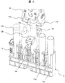
- FIG. 1 is a schematic plan view of a capping unit in the sample pretreatment system as viewed from above
- FIG. 2 is a diagram showing an outline of a sample rack, a sample container, and a capping mechanism unit.
- the stopper opening unit 1 is connected to the transport line 2 and carries the sample rack 4 from the sample rack carry-in port 3.
- sample containers 13a to 13e are mounted as shown in FIG.
- the specimen container 13a is provided with a rubber press-fit stopper
- the specimen container 13b is provided with a resin screw stopper
- the specimen container 13c is provided with a resin press-fit stopper.
- the sample containers 13d and 13e are opened sample containers.
- the loaded sample rack 4 passes through the buffering unit 5 and is transported to the sample rack identification unit 6.
- the buffering unit 5 is provided to prevent the sample rack 4 that is transported from the transport line 2 as needed.
- the sample rack identification unit 6 reads the identification number 12 assigned to each sample rack 4, transmits the identification number 12 to the control unit 50 connected by the communication cable 7, and is mounted on the sample rack 4 from the control unit 50.
- Information about the sample containers 13a to 13e and instructions regarding the contents of the opening process are obtained.
- Sample container information includes the height, diameter, presence / absence and type of each of the sample containers 13a to 13e, and instructions regarding the contents of the opening process indicate whether or not the sample containers 13a to 13e need to be opened. And instructions for processing according to the information of the specimen container, such as instructions for operating parameters for the screw plug 13b (parameters for rotational operation necessary for opening).
- the sample rack 4 After being transported to the sample rack identification unit 6, the sample rack 4 is transported to the opening position 8. An opening mechanism portion is provided above the sample rack 4 at the opening position 8.
- the opening mechanism lowers according to the information on the sample containers 13a to 13e obtained from the control unit 50 and the instruction regarding the contents of the opening process, and performs the opening operation to open the container.
- the stopper is discarded at the stopper disposal position 10. Further, the opening process is skipped for a specimen container without a stopper or a specimen container that does not require opening.
- the opening mechanism part will be described later.
- a plug detection sensor 11 for confirming the opening state is provided at the opening position 8, and when the opening process has failed, the opening operation is repeated a predetermined number of retries. If the opening process fails even if the opening operation is repeated for the number of retries, an error is generated and reported to the control unit 50, and the corresponding sample rack is taken out of the opening unit 1 and then stored in the sample pretreatment system. Are stored in an error sample rack storage section provided separately.
- the sample rack 4 passes through the sample rack outlet 9 of the opening unit 1 and is carried out to the transport line 2 to be transported to the next sample pretreatment unit.
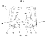
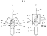
- FIG. 3 and FIG. 2 is a diagram showing an outline of the opening mechanism, the sample rack 4, and the sample containers 13a to 13e, as described above, FIG. 3 is a detailed view of the opening chuck, and FIG. 5 is an opening of the opening mechanism. It is a schematic explanatory drawing of plug operation.
- sample containers 13a to 13e with stoppers mounted on the sample rack 4 are transported via the transport line 2 and the buffering section 5 (see FIG. 1).
- the opening mechanism portion includes a clamp mechanism 14 that holds the specimen containers 13a to 13e with stoppers one by one, and a stopper chuck mechanism 15 that opens the held specimen containers with stoppers. Yes.
- the stopper chuck mechanism 15 performs an opening operation by pinching the stoppers of the stopper-attached specimen containers 13a to 13e fixed by the clamp mechanism 14 from two opposite directions and pulling them upward.
- the opening operation is started.
- the pushing portion 21 of the opening mechanism moves downward and compresses the compression spring 20
- the stopper chuck mechanism 15 opens to the left and right as shown in FIG.
- the compression spring 20 pushes the pushing portion 21 upward by a repulsive force
- the stopper chuck mechanism 15 is closed, and the stopper 23 of the stoppered specimen container 22 is sandwiched from the left and right.
- the stopper chuck mechanism 15 includes an opening chuck 15a having a rubber opening chuck 15b and a resin opening chuck 15c, and the stopper 23 of the sample container 22 is attached by these opening chucks. Hold it. Then, as shown in FIG. 5B, the stopper chuck mechanism 15 rises while rotating while holding the stopper 23 of the stoppered specimen container 22 by the spring force of the compression spring 20. Since the sample container 22 with a stopper is fixed by the clamp mechanism 14, only the stopper 23 moves and is pulled upward. In this way, the stoppered specimen container 22 is opened by the opening mechanism.
- control unit 50 issues an instruction to the plug chuck mechanism 15 based on the information on the sample containers 13a to 13e obtained by the sample rack identification unit 6, and the plug chuck mechanism 15 follows the instructions and the sample containers 13a to 13e. Opening operation is performed by changing the position according to the height and outer diameter.
- an unplugging operation is performed in which the screw plug 13b is pulled upward while applying a rotation operation that differs in rotational force, rotation speed, and the like from the press-fit plugs 13a and 13c.
- the rotation operation at the time of opening is different in operation parameters such as the rotational force and the number of rotations according to the information of the sample containers 13a to 13e.
- the stopper chuck mechanism 15 As shown in FIG. 3, the stopper chuck mechanism 15 is provided with a pair of stopper chucks 15a for opening the stopper.
- the opening chuck 15a is composed of a rubber opening chuck 15b having a shape suitable for opening the rubber-made sample container 13a and a resin opening chuck 15c having a shape suitable for a resin-made sample container. Consists of combinations.
- the rubber opening chuck 15b and the resin opening chuck 15c are made of metal such as stainless steel, for example, and are arranged so that the rubber opening chuck 15b overlaps the upper surface of the resin opening chuck 15c. It is fixed.
- the relative positions of the rubber opening chuck 15b and the resin opening chuck 15c in the direction in which the stopper is sandwiched can be changed by the screw 18. That is, the rubber opening chuck 15b is provided with a long screw hole in the direction of sandwiching the stopper, and is moved on the resin opening chuck 15c and fixed with the screw 18 at a desired position. be able to. In this way, by using the opening chuck 15a in which the rubber opening chuck 15b is superimposed on the resin opening chuck 15c, the sample container can be opened regardless of whether it is made of rubber or resin. It can be plugged.
- the rubber opening chuck 15b and the resin opening chuck 15c have tooth-like portions 19a and 19b each having a plurality of protrusions (teeth) at portions in contact with the stopper.
- the stopper 16 When the pair of opening chucks 15a sandwich the stopper from two opposite directions, the stopper is deformed by the chucking force.
- the amount of deformation differs between the rubber stopper 16 and the resin stopper 17.
- the rubber stopper 16 has a large deformation amount (FIG. 4A), and the resin stopper 17 has a small deformation amount. (FIG. 4B).
- the rubber plug 16 has a large friction and the opening chuck does not slip at the time of opening, but the resin plug 17 has a small friction and the opening chuck is easy to slide. Therefore, in the case of rubber and resin, a plug chuck having a shape that takes into consideration the respective characteristics is desirable.
- the opening chuck 15a of the present invention has a configuration in which a rubber opening chuck 15b and a resin opening chuck 15c having a shape considering each feature are combined, so that the stopper is made of rubber or resin. Even so, unsuccessful opening can be avoided.
- the tooth-like portion 19a of the rubber opening chuck 15b and the tooth-like portion 19b of the resin opening chuck 15c are pressed against each other from two opposite directions and pulled upward.
- the number of teeth of the tooth-like portion (hereinafter referred to as “the number of teeth”) differs between the tooth-like portion 19a of the rubber opening chuck 15b and the tooth-like portion 19b of the resin opening chuck 15c.
- the present invention is characterized by using the opening chuck 15a that simultaneously satisfies the conflicting requirements for the shape of the opening chuck.
- the tooth-shaped portion 19a of the rubber opening chuck 15b has more teeth than the tooth-shaped portion 19b of the resin opening chuck 15c.
- This is a shape suitable for the deformation of the rubber stopper 16, and it is possible to prevent the chucking force from being applied nonuniformly to the stopper due to the deformation and to avoid unsuccessful opening.
- the resin opening chuck 15c is easier to transmit the chucking force to the resin stopper 17 having a small deformation amount, and the teeth are more than the rubber opening chuck 15b so that the chucking force is dispersed and the stopper does not slip.
- the number shall be small. Specifically, the number of teeth of the rubber opening chuck 15b is preferably 5 to 10, and the number of teeth of the resin opening chuck 15c is preferably 3 or less. However, the number is not limited to this, and may be changed as necessary. be able to.
- the resin opening chuck 15c is arranged so as to overlap the lower surface of the rubber opening chuck 15b, but the tooth-like portion 19b in contact with the stopper is plugged from the tooth-like portion 19a of the rubber opening chuck 15b. It protrudes inward in the direction to sandwich. Therefore, when the plug chuck 15a sandwiches the plug, the resin plug chuck 15c having a small number of teeth first presses the plug, and when the plug is deformed and recessed, the rubber plug chuck 15b having the next largest number of teeth is formed. The stopper is pressed.
- the chucking force is applied to the protruding portion by the toothed portion 19a having a large number of teeth, and the entire plug 16 is pressed. Therefore, the state in which the chucking force and the deformation are not uniform is eliminated, the chucking force is maintained in the entire stopper 16, and the opening operation can be performed without failure.
- the positional relationship in which the rubber opening chuck 15b and the resin opening chuck 15c are combined can be varied with respect to the direction in which the plug is sandwiched. It is possible to respond flexibly according to differences in hardness and hardness, and any stopper can be opened without failure.
- the rubber opening chuck 15b may be arranged so as to overlap the lower surface of the resin opening chuck 15c according to the shape of the plug. Even in such an arrangement, by changing the positional relationship in which the rubber opening chuck 15b and the resin opening chuck 15c are combined, it is possible to prevent dispersion of the chuck force and deformation of the plug due to the chuck force. Even such plugs can be opened without failure.
- the rubber opening chuck 15b having a large number of teeth for preventing deformation of the stopper due to the chucking force for the elastic material including rubber, including resin.
- the resin opening chuck 15c having a small number of teeth in which the chuck force is dispersed and the stopper does not slip.
- SYMBOLS 1 Opening unit, 2 ... Conveyance line, 3 ... Sample rack inlet, 4 ... Sample rack, 5 ... Buffering part, 6 ... Sample rack identification part, 7 ... Communication cable, 8 ... Opening position, 9 ... Sample Rack outlet, 10 ... stopper disposal position, 11 ... stopper detection sensor, 12 ... rack identification number, 13a ... specimen container with rubber stopper (press-fit stopper), 13b ... specimen container with stopper made of resin (screw stopper), 13c: Sample container with a stopper made of resin (press-fit stopper), 13d, 13e ... Opened specimen container, 14 ... Clamp mechanism, 15 ... Plug chuck mechanism, 15a ...
Landscapes
- Chemical & Material Sciences (AREA)
- General Health & Medical Sciences (AREA)
- Life Sciences & Earth Sciences (AREA)
- Health & Medical Sciences (AREA)
- Analytical Chemistry (AREA)
- Biochemistry (AREA)
- Physics & Mathematics (AREA)
- General Physics & Mathematics (AREA)
- Immunology (AREA)
- Pathology (AREA)
- Chemical Kinetics & Catalysis (AREA)
- Automatic Analysis And Handling Materials Therefor (AREA)
- Devices For Opening Bottles Or Cans (AREA)
Abstract
Description
Claims (10)
- 栓つき検体容器を少なくとも1つ載置した検体ラックを搬送する搬送ラインと、前記搬送ラインで搬送されてきた検体ラックに載置されている栓つき検体容器を開栓する開栓ユニットとを有する検体前処理システムであって、
前記開栓ユニットは、前記搬送ラインで搬送されてきた前記栓つき検体容器を開栓時に保持するクランプ機構と、前記クランプ機構により保持された前記栓つき検体容器の栓を挟持し開栓する栓チャック機構とを備え、
前記栓チャック機構は、栓と接する部分に複数の突起を有する一対の開栓チャックを2種類備え、この2種類の開栓チャックが上下に重なって配置されていることを特徴とする検体前処理システム。 - 請求項1記載の検体前処理システムにおいて、
前記栓チャック機構は、前記2種類の開栓チャックの前記突起の数が互いに異なる検体前処理システム。 - 請求項1記載の検体前処理システムにおいて、
前記栓チャック機構は、前記2種類の開栓チャックのうち、上側の開栓チャックの前記突起の数が、下側の開栓チャックの前記突起の数よりも多い検体前処理システム。 - 請求項1記載の検体前処理システムにおいて、
前記栓チャック機構の2種類の開栓チャックは、前記栓つき検体容器の栓を挟持する方向の相対的な位置が可変である検体前処理システム。 - 請求項1記載の検体前処理システムにおいて、
前記栓チャック機構は、前記栓つき検体容器の栓を挟持し回転しながら上方に動くことで、前記栓つき検体容器を開栓する検体前処理システム。 - 請求項1記載の検体前処理システムにおいて、
前記検体前処理システムは、本検体前処理システムの運転制御を行う制御部と、前記検体ラックに付与された識別番号を読み取る識別部とを有し、
前記開栓ユニットは、読み取った前記識別番号に基づく前記制御部の指示により、前記栓つき検体容器の栓に応じて開栓動作を行う検体前処理システム。 - 請求項6記載の検体前処理システムにおいて、
前記開栓ユニットは、読み取った前記識別番号に基づく前記制御部の指示により、前記検体容器の開栓が不要な場合または前記検体容器に栓がない場合は、その検体容器の開栓動作を行わない検体前処理システム。 - 請求項6記載の検体前処理システムにおいて、
前記検体前処理システムは、エラー検体収納部を有し、
前記開栓ユニットは、開栓動作を失敗した場合、予め定めた所定回数だけ開栓動作を繰り返し、前記所定回数の開栓動作が全て失敗した場合には、開栓エラーとして前記エラー検体収納部に開栓動作が全て失敗した検体容器を載置した検体ラックを搬送する検体前処理システム。 - 請求項2記載の検体前処理システムにおいて、
前記2種類の開栓チャックのうち、前記突起の数が多いものは弾性材料の栓を挟持するために備え、前記突起の数が少ないものは塑性材料の栓を挟持するために備える検体前処理システム。 - 請求項2記載の検体前処理システムにおいて、
前記栓チャック機構は、前記2種類の開栓チャックのうち、上側の開栓チャックの前記突起の数が、下側の開栓チャックの前記突起の数よりも少ない検体前処理システム。
Priority Applications (4)
| Application Number | Priority Date | Filing Date | Title |
|---|---|---|---|
| EP09750319.7A EP2282212B1 (en) | 2008-05-22 | 2009-04-14 | System for pretreating sample |
| US12/992,932 US8857295B2 (en) | 2008-05-22 | 2009-04-14 | System for pretreating sample |
| JP2010512922A JP5179577B2 (ja) | 2008-05-22 | 2009-04-14 | 検体前処理システム |
| CN200980118243.2A CN102037364B (zh) | 2008-05-22 | 2009-04-14 | 样本前处理系统 |
Applications Claiming Priority (2)
| Application Number | Priority Date | Filing Date | Title |
|---|---|---|---|
| JP2008134077 | 2008-05-22 | ||
| JP2008-134077 | 2008-05-22 |
Publications (1)
| Publication Number | Publication Date |
|---|---|
| WO2009141957A1 true WO2009141957A1 (ja) | 2009-11-26 |
Family
ID=41339901
Family Applications (1)
| Application Number | Title | Priority Date | Filing Date |
|---|---|---|---|
| PCT/JP2009/001722 Ceased WO2009141957A1 (ja) | 2008-05-22 | 2009-04-14 | 検体前処理システム |
Country Status (5)
| Country | Link |
|---|---|
| US (1) | US8857295B2 (ja) |
| EP (1) | EP2282212B1 (ja) |
| JP (1) | JP5179577B2 (ja) |
| CN (1) | CN102037364B (ja) |
| WO (1) | WO2009141957A1 (ja) |
Cited By (11)
| Publication number | Priority date | Publication date | Assignee | Title |
|---|---|---|---|---|
| JP2012126410A (ja) * | 2010-12-14 | 2012-07-05 | Molex Inc | 自動栓抜き装置 |
| WO2013002216A1 (ja) * | 2011-06-30 | 2013-01-03 | 株式会社日立ハイテクノロジーズ | 栓体開閉機構およびそれを備えた自動分析システム |
| WO2013002213A1 (ja) * | 2011-06-30 | 2013-01-03 | 株式会社日立ハイテクノロジーズ | 自動分析システム |
| JP2013076697A (ja) * | 2011-09-29 | 2013-04-25 | F Hoffmann-La Roche Ag | 幾何学的な管のデータを備えた試料管の操作 |
| WO2013094238A1 (ja) * | 2011-12-22 | 2013-06-27 | 株式会社島津製作所 | 容器設置機構及びオートサンプラ |
| JP2013152214A (ja) * | 2011-11-30 | 2013-08-08 | Andreas Hettich Gmbh & Co Kg | サンプル容器取扱方法、サンプル容器取扱装置 |
| US20130305846A1 (en) * | 2011-01-31 | 2013-11-21 | Hitachi High-Technologies Corporation | Automatic analysis system |
| JP2015077641A (ja) * | 2013-10-15 | 2015-04-23 | 川崎重工業株式会社 | ロボットハンド及びロボット |
| JPWO2018025608A1 (ja) * | 2016-08-03 | 2019-06-27 | 株式会社日立ハイテクノロジーズ | 栓処理装置およびそれを備えた検体検査自動化システム |
| JP2020511640A (ja) * | 2017-03-09 | 2020-04-16 | ホロジック, インコーポレイテッドHologic, Inc. | 生物学的検体の自動調製システム及び方法 |
| JP2022178539A (ja) * | 2021-05-20 | 2022-12-02 | 株式会社椿本チエイン | デキャピング装置 |
Families Citing this family (20)
| Publication number | Priority date | Publication date | Assignee | Title |
|---|---|---|---|---|
| EP2538225A1 (en) * | 2011-06-20 | 2012-12-26 | F. Hoffmann-La Roche AG | System for processing closed sample tubes |
| EP2538227B1 (en) * | 2011-06-20 | 2015-02-18 | F. Hoffmann-La Roche AG | Device for decapping and recapping sample tubes |
| CN104609348B (zh) * | 2015-01-26 | 2017-01-25 | 长春迪瑞医疗科技股份有限公司 | 一种用于样本容器的自动开盖装置 |
| WO2016130964A1 (en) | 2015-02-13 | 2016-08-18 | Abbott Laboratories | Decapping and capping apparatus, systems and methods for use in diagnostic analyzers |
| US12392692B2 (en) | 2017-03-09 | 2025-08-19 | Hologic, Inc. | Systems for automated preparation of biological specimens |
| CN111655593B (zh) * | 2017-12-22 | 2022-06-14 | 西氏医药服务公司 | 用于无菌填充小容量瓶的包装系统 |
| CN108802414B (zh) * | 2018-06-29 | 2022-05-20 | 迈克医疗电子有限公司 | 掉杯阀的判定方法和装置、反应杯添加的控制方法和装置 |
| EP4051622B1 (en) | 2019-10-29 | 2026-04-29 | Beckman Coulter, Inc. | Sample tube decapper |
| MX2022005127A (es) | 2019-10-29 | 2022-08-04 | Tmrw Life Sciences Inc | Aparato para facilitar la transferencia de especimenes biologicos almacenados en condiciones criogenicas. |
| US11817187B2 (en) | 2020-05-18 | 2023-11-14 | TMRW Life Sciences, Inc. | Handling and tracking of biological specimens for cryogenic storage |
| US11236811B1 (en) | 2020-09-18 | 2022-02-01 | The Hilliard Corporation | Center differential and drive system for four wheel drive |
| JP7610303B2 (ja) | 2020-09-24 | 2025-01-08 | ティーエムアールダブリュ ライフサイエンシーズ,インコーポレイテツド | 極低温条件で保管された生物学的試料の移送を容易にするためのワークステーション及び装置 |
| WO2022066192A1 (en) | 2020-09-24 | 2022-03-31 | TMRW Life Sciences, Inc. | Cryogenic storage system with sensors to measure one or more parameters therewithin |
| JP7545768B2 (ja) | 2020-10-02 | 2024-09-05 | ティーエムアールダブリュ ライフサイエンシーズ,インコーポレイテツド | 無線トランスポンダタグ付き試料容器及び/又はキャリアのための位置合わせ機構を有する問い合わせ装置及び/又はシステム |
| USD963194S1 (en) | 2020-12-09 | 2022-09-06 | TMRW Life Sciences, Inc. | Cryogenic vial carrier |
| EP4259333B1 (en) | 2020-12-10 | 2026-03-04 | TMRW Life Sciences, Inc. | Specimen holder with wireless transponder |
| EP4252009B1 (en) * | 2021-01-13 | 2025-03-05 | TMRW Life Sciences, Inc. | System to pick and/or place specimen containers |
| EP4086635B1 (en) * | 2021-05-04 | 2024-08-28 | Roche Diagnostics GmbH | A preanalytic system for preparing a laboratory sample container |
| US12527318B2 (en) | 2021-10-08 | 2026-01-20 | TMRW Life Sciences, Inc. | Systems, apparatus and methods to pick and/or place specimen containers |
| US20240255535A1 (en) * | 2023-01-26 | 2024-08-01 | Helix OpCo, LLC | Decapping of screw cap test tubes |
Citations (6)
| Publication number | Priority date | Publication date | Assignee | Title |
|---|---|---|---|---|
| JPH05302927A (ja) * | 1992-04-24 | 1993-11-16 | Nittec Co Ltd | 分析装置 |
| JP2000039438A (ja) * | 1998-07-14 | 2000-02-08 | Bayer Corp | 自動キャップ除去装置 |
| JP2003014770A (ja) | 2001-06-29 | 2003-01-15 | Aloka Co Ltd | 開栓装置及び分注装置 |
| JP2005075395A (ja) * | 2003-08-29 | 2005-03-24 | Teruaki Ito | 試験管栓取外し装置 |
| JP2005271991A (ja) * | 2004-03-26 | 2005-10-06 | Ids:Kk | 試験管栓取外し装置 |
| JP2007078363A (ja) * | 2005-09-09 | 2007-03-29 | Aloka Co Ltd | 検体前処理システム及び方法 |
Family Cites Families (13)
| Publication number | Priority date | Publication date | Assignee | Title |
|---|---|---|---|---|
| US3675916A (en) * | 1970-09-21 | 1972-07-11 | Wilton Corp | Vise assembly |
| CA2087816A1 (en) * | 1992-02-03 | 1993-08-04 | Ronald L. Meibach | Cholesterol-reduced whole egg product |
| JP3241105B2 (ja) * | 1992-06-22 | 2001-12-25 | 株式会社システムスタック | 検体容器の開栓方法及び装置 |
| JP3359701B2 (ja) * | 1992-06-22 | 2002-12-24 | 株式会社システムスタック | 検体容器の開栓装置 |
| JPH0627102A (ja) * | 1992-07-07 | 1994-02-04 | Sekisui Chem Co Ltd | 採液管用栓体及び開栓装置 |
| JP3008403U (ja) * | 1994-08-30 | 1995-03-14 | 達夫 横田 | 瓶蓋の開放具 |
| JP3413290B2 (ja) * | 1994-09-21 | 2003-06-03 | 上田日本無線株式会社 | 自動開栓装置 |
| JPH09243643A (ja) * | 1996-03-11 | 1997-09-19 | Hitachi Ltd | シール栓自動開栓装置 |
| JPH11230967A (ja) * | 1998-02-12 | 1999-08-27 | Mitsubishi Kagaku Bio Clinical Laboratories Inc | 自動開栓装置 |
| JP3854283B2 (ja) * | 2004-04-26 | 2006-12-06 | 株式会社アイディエス | 剥離式キャップの矯正開蓋装置 |
| FR2888328B1 (fr) * | 2005-07-08 | 2013-09-20 | Horiba Abx Sas | Procede automatise de preparation d'analyse d'echantillons de sang total et dispositif automatise pour sa mise en oeuvre |
| JP4890998B2 (ja) * | 2006-08-22 | 2012-03-07 | 株式会社日立ハイテクノロジーズ | 検体処理システム |
| JP3151523U (ja) * | 2009-04-15 | 2009-06-25 | 有限会社中尾製作所 | 蓋開閉具 |
-
2009
- 2009-04-14 CN CN200980118243.2A patent/CN102037364B/zh active Active
- 2009-04-14 WO PCT/JP2009/001722 patent/WO2009141957A1/ja not_active Ceased
- 2009-04-14 JP JP2010512922A patent/JP5179577B2/ja active Active
- 2009-04-14 EP EP09750319.7A patent/EP2282212B1/en active Active
- 2009-04-14 US US12/992,932 patent/US8857295B2/en active Active
Patent Citations (6)
| Publication number | Priority date | Publication date | Assignee | Title |
|---|---|---|---|---|
| JPH05302927A (ja) * | 1992-04-24 | 1993-11-16 | Nittec Co Ltd | 分析装置 |
| JP2000039438A (ja) * | 1998-07-14 | 2000-02-08 | Bayer Corp | 自動キャップ除去装置 |
| JP2003014770A (ja) | 2001-06-29 | 2003-01-15 | Aloka Co Ltd | 開栓装置及び分注装置 |
| JP2005075395A (ja) * | 2003-08-29 | 2005-03-24 | Teruaki Ito | 試験管栓取外し装置 |
| JP2005271991A (ja) * | 2004-03-26 | 2005-10-06 | Ids:Kk | 試験管栓取外し装置 |
| JP2007078363A (ja) * | 2005-09-09 | 2007-03-29 | Aloka Co Ltd | 検体前処理システム及び方法 |
Cited By (22)
| Publication number | Priority date | Publication date | Assignee | Title |
|---|---|---|---|---|
| JP2012126410A (ja) * | 2010-12-14 | 2012-07-05 | Molex Inc | 自動栓抜き装置 |
| US20130305846A1 (en) * | 2011-01-31 | 2013-11-21 | Hitachi High-Technologies Corporation | Automatic analysis system |
| US8834814B2 (en) * | 2011-01-31 | 2014-09-16 | Hitachi High-Technologies Corporation | Automatic analysis system with removal, tracking, and mounting of stopper bodies |
| WO2013002216A1 (ja) * | 2011-06-30 | 2013-01-03 | 株式会社日立ハイテクノロジーズ | 栓体開閉機構およびそれを備えた自動分析システム |
| WO2013002213A1 (ja) * | 2011-06-30 | 2013-01-03 | 株式会社日立ハイテクノロジーズ | 自動分析システム |
| JPWO2013002213A1 (ja) * | 2011-06-30 | 2015-02-23 | 株式会社日立ハイテクノロジーズ | 自動分析システム |
| JPWO2013002216A1 (ja) * | 2011-06-30 | 2015-02-23 | 株式会社日立ハイテクノロジーズ | 栓体開閉機構およびそれを備えた自動分析システム |
| US9505507B2 (en) | 2011-06-30 | 2016-11-29 | Hitachi High-Technologies Corporation | Cap opening and closing mechanism and automatic analyzer including the same |
| US9500571B2 (en) | 2011-09-29 | 2016-11-22 | Roche Diagnostics Operations, Inc. | Handling of sample tubes comprising geometric tube data |
| JP2013076697A (ja) * | 2011-09-29 | 2013-04-25 | F Hoffmann-La Roche Ag | 幾何学的な管のデータを備えた試料管の操作 |
| US9855556B2 (en) | 2011-09-29 | 2018-01-02 | Roche Diagnostics Operations, Inc. | Handling of sample tubes comprising geometric tube data |
| JP2013152214A (ja) * | 2011-11-30 | 2013-08-08 | Andreas Hettich Gmbh & Co Kg | サンプル容器取扱方法、サンプル容器取扱装置 |
| US9340312B2 (en) | 2011-11-30 | 2016-05-17 | Andreas Hettich Gmbh & Co. Kg | Method and a device for handling sample containers |
| JPWO2013094238A1 (ja) * | 2011-12-22 | 2015-04-27 | 株式会社島津製作所 | 容器設置機構及びオートサンプラ |
| WO2013094238A1 (ja) * | 2011-12-22 | 2013-06-27 | 株式会社島津製作所 | 容器設置機構及びオートサンプラ |
| JP2015077641A (ja) * | 2013-10-15 | 2015-04-23 | 川崎重工業株式会社 | ロボットハンド及びロボット |
| JPWO2018025608A1 (ja) * | 2016-08-03 | 2019-06-27 | 株式会社日立ハイテクノロジーズ | 栓処理装置およびそれを備えた検体検査自動化システム |
| JP2020511640A (ja) * | 2017-03-09 | 2020-04-16 | ホロジック, インコーポレイテッドHologic, Inc. | 生物学的検体の自動調製システム及び方法 |
| TWI755498B (zh) * | 2017-03-09 | 2022-02-21 | 美商好樂杰公司 | 自動化製備生物樣本之系統及方法 |
| TWI792862B (zh) * | 2017-03-09 | 2023-02-11 | 美商好樂杰公司 | 自動化製備生物樣本之方法 |
| JP2022178539A (ja) * | 2021-05-20 | 2022-12-02 | 株式会社椿本チエイン | デキャピング装置 |
| JP7284409B2 (ja) | 2021-05-20 | 2023-05-31 | 株式会社椿本チエイン | デキャピング装置 |
Also Published As
| Publication number | Publication date |
|---|---|
| EP2282212A1 (en) | 2011-02-09 |
| CN102037364A (zh) | 2011-04-27 |
| EP2282212B1 (en) | 2018-11-28 |
| JP5179577B2 (ja) | 2013-04-10 |
| EP2282212A4 (en) | 2017-11-15 |
| CN102037364B (zh) | 2014-06-11 |
| US8857295B2 (en) | 2014-10-14 |
| US20110088517A1 (en) | 2011-04-21 |
| JPWO2009141957A1 (ja) | 2011-09-29 |
Similar Documents
| Publication | Publication Date | Title |
|---|---|---|
| JP5179577B2 (ja) | 検体前処理システム | |
| US9772342B2 (en) | Dispatching device, sample distribution system and laboratory automation system | |
| JP5775160B2 (ja) | 栓体開閉機構およびそれを備えた自動分析システム | |
| US10359441B2 (en) | Reagent station for an automated analysis device | |
| JP6050585B2 (ja) | 生体サンプルホルダをクランプするための装置および方法 | |
| US20150268258A1 (en) | Apparatus For Gripping and Holding Diagnostic Cassettes | |
| CA2491999A1 (en) | Apparatus and methods for automated handling and embedding of tissue samples | |
| JP2009036511A (ja) | 検体前処理システム | |
| CN105593687A (zh) | 自动分析装置 | |
| JP4160364B2 (ja) | 試薬容器および自動分析装置 | |
| EP2883667B1 (en) | Device and method for gripping vessels | |
| CN109564234B (zh) | 栓处理装置及具备其的检体检查自动化系统 | |
| JP5393321B2 (ja) | 自動分析装置 | |
| US8037993B2 (en) | Container carrier turning device for a container carrier conveyor | |
| CN113544517A (zh) | 检体托架 | |
| JP6101091B2 (ja) | 検体容器移動システムおよび検体容器移動方法 | |
| JP6381910B2 (ja) | 閉止装置 | |
| JP2006292696A (ja) | 検体ラック、及び検体ラック用アダプタ | |
| JP2024523834A (ja) | デュアル回転軸アンキャッパを備える自動サンプラーシステム | |
| CN109603950B (zh) | 一种试剂瓶夹持组件、自动加载机构及其加载方法 | |
| CN114585928A (zh) | 连接装置及检体检查自动化系统 | |
| JP6850654B2 (ja) | 閉栓装置及びシステム | |
| JP2000314737A (ja) | 検体搬送システム | |
| WO2018168438A1 (ja) | 試料容器移載装置 | |
| JP2006189311A (ja) | 検体処理装置および検体処理システム |
Legal Events
| Date | Code | Title | Description |
|---|---|---|---|
| WWE | Wipo information: entry into national phase |
Ref document number: 200980118243.2 Country of ref document: CN |
|
| 121 | Ep: the epo has been informed by wipo that ep was designated in this application |
Ref document number: 09750319 Country of ref document: EP Kind code of ref document: A1 |
|
| WWE | Wipo information: entry into national phase |
Ref document number: 2010512922 Country of ref document: JP |
|
| WWE | Wipo information: entry into national phase |
Ref document number: 12992932 Country of ref document: US |
|
| WWE | Wipo information: entry into national phase |
Ref document number: 2009750319 Country of ref document: EP |
|
| NENP | Non-entry into the national phase |
Ref country code: DE |