WO2009144877A1 - Sangle pelvienne - Google Patents
Sangle pelvienne Download PDFInfo
- Publication number
- WO2009144877A1 WO2009144877A1 PCT/JP2009/002049 JP2009002049W WO2009144877A1 WO 2009144877 A1 WO2009144877 A1 WO 2009144877A1 JP 2009002049 W JP2009002049 W JP 2009002049W WO 2009144877 A1 WO2009144877 A1 WO 2009144877A1
- Authority
- WO
- WIPO (PCT)
- Prior art keywords
- compression body
- pelvic
- patient
- band
- hip joint
- Prior art date
- Legal status (The legal status is an assumption and is not a legal conclusion. Google has not performed a legal analysis and makes no representation as to the accuracy of the status listed.)
- Ceased
Links
Images


Classifications
-
- A—HUMAN NECESSITIES
- A61—MEDICAL OR VETERINARY SCIENCE; HYGIENE
- A61F—FILTERS IMPLANTABLE INTO BLOOD VESSELS; PROSTHESES; DEVICES PROVIDING PATENCY TO, OR PREVENTING COLLAPSING OF, TUBULAR STRUCTURES OF THE BODY, e.g. STENTS; ORTHOPAEDIC, NURSING OR CONTRACEPTIVE DEVICES; FOMENTATION; TREATMENT OR PROTECTION OF EYES OR EARS; BANDAGES, DRESSINGS OR ABSORBENT PADS; FIRST-AID KITS
- A61F5/00—Orthopaedic methods or devices for non-surgical treatment of bones or joints; Nursing devices ; Anti-rape devices
- A61F5/01—Orthopaedic devices, e.g. long-term immobilising or pressure directing devices for treating broken or deformed bones such as splints, casts or braces
- A61F5/02—Orthopaedic corsets
- A61F5/028—Braces for providing support to the lower back, e.g. lumbo sacral supports
-
- A—HUMAN NECESSITIES
- A61—MEDICAL OR VETERINARY SCIENCE; HYGIENE
- A61F—FILTERS IMPLANTABLE INTO BLOOD VESSELS; PROSTHESES; DEVICES PROVIDING PATENCY TO, OR PREVENTING COLLAPSING OF, TUBULAR STRUCTURES OF THE BODY, e.g. STENTS; ORTHOPAEDIC, NURSING OR CONTRACEPTIVE DEVICES; FOMENTATION; TREATMENT OR PROTECTION OF EYES OR EARS; BANDAGES, DRESSINGS OR ABSORBENT PADS; FIRST-AID KITS
- A61F5/00—Orthopaedic methods or devices for non-surgical treatment of bones or joints; Nursing devices ; Anti-rape devices
- A61F5/01—Orthopaedic devices, e.g. long-term immobilising or pressure directing devices for treating broken or deformed bones such as splints, casts or braces
- A61F5/0193—Apparatus specially adapted for treating hip dislocation; Abduction splints
Definitions
- the present invention relates to a pelvic belt that is worn by a patient who has difficulty walking due to paralysis or the like.
- Patent Document 1 discloses a walking assistance device configured to apply assisting force to a lower limb during walking.
- the walking assist device includes a lumbar part mounting unit that is mounted on a patient's lumbar part, a lower limb mounting unit that is mounted on a lower limb, and a drive unit that generates assisting force.
- the waist mounting portion has a back support portion formed so as to go backward from a portion corresponding to the left and right iliac bones, and a belt portion for fixing the back support portion to the waist portion.
- the drive unit incorporates the electric motor with a reduction gear, and is attached so that a backrest part and a leg mounting
- the back support part of the walking assist device needs to be firmly attached to the patient's waist, it is difficult to change the mounting position of the back support part. Therefore, the mounting position cannot be adjusted in accordance with the state of paralysis or the degree of recovery of the patient.
- the drive unit of the walking assist device incorporates an electric motor with a speed reducer, a control device and a power source are required, and the price of the device is soaring that it is difficult to spread widely.
- the present invention has been made in view of such points, and its purpose is to make the patient's walking posture close to a normal posture when a patient who has difficulty walking rehabilitates, etc. Sufficient therapeutic effect by not only obstructing pelvic movement in the normal range and obtaining sufficient muscle penetration effect, and changing the wearing state according to the paralysis state and recovery degree of each individual patient The purpose is to reduce the cost.
- a compression body that compresses the hip joint from the back can be fixed to the patient by a fixing member.
- a configuration in the first invention, includes a compression body that compresses the hip joint, and a fixing member that presses and fixes the compression body toward the hip joint from behind.
- the fixing member does not need to be strongly wound like the belt portion of the conventional example, and may be wound with such a strength that the compression body can be pressed against the hip joint.
- the pelvic belt Accordingly, it becomes difficult for the pelvic belt to obstruct the movement of the normal range of the pelvis, and the position where the fixing member is wound and the position of the compression body can be finely adjusted according to the state of paralysis and the degree of recovery of each patient. . Further, since the compression body is pressed against the hip joint by the fixing member, a control device and a power source are unnecessary, and the structure can be simplified as compared with the case where the drive unit is provided.
- the fixing member is configured to fix the compression body to a recessed portion formed from the vicinity of the lateral edge of the greater gluteus muscle in the buttocks to the outside.
- the pressing surface of the compression body is curved so as to bulge.
- This configuration makes it possible to prevent pain from being applied to the patient when the compression body is pressed against the hip joint.
- the compression body is configured to have an insertion portion through which the fixing member is inserted.
- the pressing member and the fixing member are integrated in a state where the fixing member is inserted through the insertion portion of the pressing member.
- the fixing member is formed in a long shape and has an elastic portion that expands and contracts in the longitudinal direction.
- a pelvic posterior support portion is provided that covers a portion corresponding to the iliac wing and the sacrum of the acetabulum.
- the pelvis can be supported from the rear side by the pelvic rear support portion.
- a pubic support portion is provided that covers a portion corresponding to the pubic joint of the hipbone.
- the pelvis can be supported from the front side by the pubic support portion.
- the walking posture is not provided without providing a drive unit as in the conventional example. Can be brought close to normal. This makes it difficult for the pelvic belt to obstruct the movement of the pelvis in the normal range, so that the muscles can be fully assisted, and the position of the compression body according to the state of paralysis and the degree of recovery of each patient The therapeutic effect can be sufficiently obtained by fine-tuning. Furthermore, the structure can be simplified and the cost can be reduced.
- the compression body can be arranged while avoiding thick muscles such as the gluteus maxims, and the displacement of the compression body can be suppressed.
- the compression force by a compression body can be made to act reliably on a hip joint, and it can suppress effectively that a hip joint collapse
- the compression force can be reliably applied to the hip joint while avoiding pain to the patient at the time of wearing.
- the fixing member is integrated with the insertion portion of the compression body, the position of the compression body with respect to the fixation member can be easily changed. The position where the force is applied can be adjusted.
- the fixing member since the fixing member has the elastic portion, the pressing force on the hip joint can be easily adjusted.
- the patient's pelvis can be supported from the rear side, and according to the seventh aspect, the patient's pelvis can be supported from the front side. According to these inventions, since the walking posture can be brought close to normal even in a severe case, the applicable cases can be enlarged.
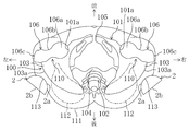
- FIG. 1 is a diagram showing the anatomy of the human pelvis and the vicinity of the hip joint viewed from the rear.
- FIG. 2 is a diagram showing the anatomy of the vicinity of the hip joint from the top of the human pelvis in a state where the compression body is pressed.
- FIG. 3 is a front view showing a usage state of the pelvic belt according to the first embodiment.
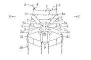
- FIG. 4 is a rear view showing a usage state of the pelvic belt according to the first embodiment.
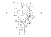
- FIG. 5 is a side view showing a usage state of the pelvic belt according to the first embodiment.
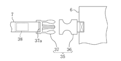
- FIG. 6 is an enlarged view showing a joint portion between the connection band and the pubic support panel according to the modification.
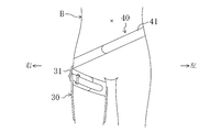
- FIG. 7 is a view corresponding to FIG. 3 according to the second embodiment.
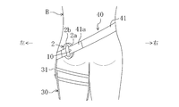
- FIG. 8 is a view corresponding to FIG. 4 according to the second embodiment.
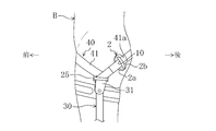
- FIG. 9 is a view corresponding to FIG. 5 according to the second embodiment.
- FIGS. 3-5 shows the use condition of the pelvic belt 1 which concerns on Embodiment 1 of this invention.
- the pelvic belt 1 is used when a patient A who has difficulty walking due to paralysis or the like performs rehabilitation.
- the anatomy around the human pelvis and the femur will be described before describing the structure and usage of the pelvic belt 1.
- the pelvis 100 includes a hipbone 101, a sacrum 102 on the rear side of the left and right central part, and a tailbone (not shown) on the front side of the central part.
- the hipbone 101 is formed by the fusion of the iliac bone 103, the seat bone 104, and the pubic bone 105 (shown in FIG. 2).
- the iliac bone 103 has iliac wings 103a that project from side to side.
- the acetabulum 101 includes an acetabulum 101 a that wraps the femoral head 106 a at the proximal end of the femur 106, and the hip joint 110 is configured by the acetabulum 101 a and the proximal end of the femur 106.
- the hip joint 110 is configured by the acetabulum 101 a and the proximal end of the femur 106.
- At the proximal end of the femur 106 there are a femoral buttocks 106b and a femoral trochanter 106c in addition to the femoral head 106a.
- the buttocks 111 (shown in FIG. 2) are rich in muscles such as the gluteus maxims 112 and subcutaneous tissues.
- the pelvic belt 1 is in a state in which the compression bodies 2 and 2 (see FIG. 2) respectively disposed in the left and right depressions 113 of the buttocks 111 at the back of the hip joint 110 and the compression bodies 2 and 2 are pressed toward the hip joint 110.
- Left and right compression body fixing bands 3 and 3 for fixing a pelvic posterior support panel 4 formed so as to cover a portion corresponding to the rear side of the pelvis 100, and a panel for fixing the pelvis posterior support panel 4
- Fixing bands 5, 5 shown in FIGS. 3 and 5
- a pubic support panel 6 shown in FIGS.
- left indicates the left side of the patient A wearing the pelvic belt 1
- right indicates the right side of the patient A.
- each compression body 2 has a shape in which a hard tennis ball is divided into about half, and is composed of a curved surface 2 a that bulges and is hemispherically curved when pressed against the patient A.
- the side opposite to the curved surface 2a is constituted by a flat surface 2b.
- the diameter of the compression body 2 is set to 50 mm or more and 100 mm or less.
- the hardness on the curved surface 2a side of the compression body 2 is set to be the same as the hardness of the hard tennis ball, and is hardly deformed when pressed against the hip joint 110. As shown in FIGS.
- a loop-shaped insertion portion 10 through which the compression body fixing band 3 is inserted is formed on the flat surface 2 b of the compression body 2.
- the size of the compression body 2 can be changed to suit the sex, physique, symptom, and the like of the patient A. Moreover, the hardness and shape of the compression body 2 can be changed similarly. Moreover, you may comprise the curved surface 2a side of the compression body 2 with soft materials, such as a gel material, for example. Moreover, you may make the compression body 2 smaller than the half size of a hard tennis ball.
- the pelvic posterior support panel 4 wraps around the portion corresponding to the sacrum 102 from the portion corresponding to the left iliac wing 103a of the patient A to the portion corresponding to the right iliac wing 103a. It extends and is formed so as to cover them.
- Left and right iliac wing cover portions 4a and 4b are provided on the left and right sides of the pelvic posterior support panel 4 so as to extend upward and cover portions corresponding to the left and right iliac wings 103a and 103a, respectively.
- a sacrum cover portion 4 c that extends downward and covers a portion corresponding to the sacrum 102 is provided at the center in the left-right direction of the pelvic rear support panel 4.
- one end portion of the left panel fixing band 5 is connected to the left iliac wing cover portion 4a of the pelvic posterior support panel 4 by a rivet 15 so as to be vertically rotatable.
- the other end side of the left panel fixing band 5 extends to the right side.
- One end portion of the right panel fixing band 5 is connected to the right iliac wing cover portion 4b of the pelvic posterior support panel 4 so as to be vertically rotatable by a rivet (not shown), like the left band 5.
- the other end extends to the left side.
- the left and right panel fixing bands 5 and 5 are overlapped in front of the abdomen and fixed with a hook-and-loop fastener (not shown). The tightening degree of the panel fixing band 5 can be adjusted by the fixing position of the surface fastener.
- the pubic support panel 6 is arranged away from the panel fixing band 5 and extends in the vertical direction.
- One end of the left connecting band 7 is connected to the left side of the upper end portion of the pubic support panel 6 by a rivet 16 so as to be rotatable in the vertical direction.
- the other end portion of the left connecting band 7 is connected to the left iliac wing cover portion 4a so as to be vertically rotatable by a rivet 15 common to the left panel fixing band 5.
- one end portion of the right connecting band 7 is similarly connected to the right side of the upper end portion of the pubic support panel 6 by a rivet 16.
- the other end portion of the right connecting band 7 is connected to the right iliac wing cover portion 4b so as to be rotatable in the vertical direction by a common rivet with the right panel fixing band 5.
- One end of the left hip joint outer support band 8 is connected to the left side of the vertical center portion of the pubic support panel 6 by a rivet 17 so as to be rotatable in the vertical direction.
- the other end of the left hip joint outer support band 8 is connected to the left side of the sacrum cover portion 4 c of the pelvis rear support panel 4 by a rivet 18 so as to be vertically rotatable.
- the right hip joint outer support band 8 is connected to the right side of the central part in the vertical direction of the pubic support panel 6 and the right side of the sacrum cover part 4c of the pelvic rear support panel 4.
- Elastic portions 8a and 8a made of rubber that expands and contracts in the longitudinal direction are provided at the longitudinal intermediate portions of the left and right hip joint outer support bands 8 and 8, respectively.
- One end portion of the left compression body fixing band 3 is connected to the left side of the lower end portion of the pubic support panel 6 by a rivet 19 so as to be rotatable in the vertical direction.
- the compression body fixing band 3 is formed to be wound around a portion corresponding to the pelvis 100.
- the other end of the left compression body fixing band 3 can be rotated in the vertical direction by the rivet 20 at a position below the rivet 18 of the sacral cover portion 4 c of the pelvic rear support panel 4. It is connected to.
- An elastic part 3a that expands and contracts in the longitudinal direction is provided in the middle part in the longitudinal direction of the left compression body fixing band 3 in the same manner as the elastic part 8a.
- the elastic portion 3 a is inserted through the insertion portion 10 of the compression body 2, and the elastic portion 3 a is in contact with the flat surface 2 b of the compression body 2.
- the elastic force of this elastic part 3a can be set arbitrarily, and the pressing force of the compression body 2 can be adjusted by this elastic force. Further, since the compression body fixing band 3 is merely inserted through the insertion portion 10 of the compression body 2, the position of the compression body 2 with respect to the compression body fixation band 3 can be easily changed.
- a ring 25 is provided in the middle portion in the longitudinal direction of the compression body fixing band 3 on the left side.
- the ring 25 is fixed to a fixing portion 31 at the upper end portion of the lower limb orthosis 30 attached to the left limb of the patient A. Since this lower limb orthosis 30 is generally used by patients whose lower body is paralyzed, detailed description thereof is omitted.
- the position of the fixing part 31 can be adjusted in the vertical direction.
- the position of the compression body 2 can be changed also by adjusting the position of the fixing portion 31.
- the ring 25 is positioned below the compression body 2 when attached to the patient A. Therefore, the left compression body fixing band 3 in the mounted state is inclined downward from the sacrum 102 side toward the left side as shown in FIG. 4 and extends to the fixing portion 31 of the lower limb orthosis 30, and then shown in FIG. It bends and extends obliquely upward toward the pubic bone 105 side.
- the compression body fixing band 3 on the right side is connected to the right side of the upper part of the pubic support panel 6 and the right side of the sacrum cover part 4c of the pelvic posterior support panel 4, and further, an elastic part 3a, A ring (not shown) fixed to the fixing portion 31 of the lower limb orthosis 30 is provided.
- one end of the left perineum band 9 is connected to the lower left side of the pubic support panel 6 by a rivet 21 so as to be rotatable in the left-right direction.
- the left perineum band 9 extends rearward through the left side of the perineum of patient A, and the other end is located below the rivet 20 of the sacral cover portion 4c of the pelvic posterior support panel 4 and is a rivet 22.
- the right perineal band 9 is connected to the pubic support panel 6 and the sacral cover 4c. The perineal band 9, 9 prevents the pelvis support panel 4 and the pubic support panel 6 from shifting upward.
- the connecting band 7, the hip outer support band 8, and the perineal band 9 can be detached from the pelvis support panel 4 and the pubic support panel 6.
- the lengths of the connecting band 7, the hip joint outer support band 8, the compression body fixing band 3, and the perineal band 9 can be arbitrarily set according to the patient A.
- the lower limb orthosis 30 is attached to the patient A, and then the pelvic belt 1 is attached.
- the left and right compression bodies 2 and 2 are disposed in the recesses 113 and 113 of the buttocks 111.
- the position of each compression body 2 is preferably a position where the curved surface 2a faces the vicinity of the femoral head 106a and is compressed from the rear and obliquely outward to the inside.
- the position adjustment of the compression body 2 can be easily performed because the compression body fixing band 3 is merely inserted through the insertion portion 10 of the compression body 2.
- the position of the fixing part 31 of the lower limb orthosis 30 is adjusted, and the inclination angle of the compression body fixing band 3 is set so that the compression body 2 is stabilized in the recess 113. Further, the tightening degree of the panel fixing band 5 is also adjusted.
- the compression body 2 When the pelvic belt 1 is mounted, the compression body 2 is pressed against the hip joint 110 by the compression body fixing band 3, and the hip joint 110 is compressed from the rear. At this time, since the compression bodies 2 and 2 are located in the depressions 113 and 113 having no thick muscles, the compression force by the compression bodies 2 and 2 can be reliably applied to the hip joint 110. As a result, the hip joint 110 is prevented from collapsing backward during walking, and the pelvis 100 can be kept small, so that the walking posture is brought close to normal without applying the assisting force by the drive unit as in the conventional example. It becomes possible.
- the compression bodies 2 and 2 are located in the depressions 113 and 113 during walking, it is possible to stabilize the position without being displaced.
- the compression body fixing band 3 may be wound with a strength that can compress the compression body 2 against the hip joint 110. Accordingly, the pelvic belt 1 is difficult to inhibit the normal range movement of the pelvis 100, and the position where the compression body fixing band 3 is wound and the position of the compression body 2 are matched to the paralysis state and recovery degree of each patient A. Fine adjustment is possible.
- the pelvis support panel 4 and the pubic support panel 6 are provided, the pelvis 100 of the patient A can be supported from the rear side and the front side, and the walking posture is normal even in severe cases. It becomes possible to approach.
- the compression bodies 2 and 2 arranged at the site corresponding to the back of the hip joint 110 of the patient A are wound around the site corresponding to the pelvis 100. Since the compression body fixing band 3 formed as described above is pressed against the hip joint 110 and fixed, the walking posture can be brought close to normal without providing a conventional drive unit. As a result, the movement of the pelvis 100 in the normal range can be allowed to obtain a muscle facilitating effect sufficiently, and the compression bodies 2 and 2 can be adjusted in accordance with the state of paralysis and the degree of recovery of each patient A. The therapeutic effect can be sufficiently obtained by adjusting the position. Furthermore, the structure can be simplified and the cost can be reduced.
- the compression force can be reliably applied to the hip joint 110 without causing pain to the patient A during wearing. .
- the compression bodies 2 and 2 are pressed against the left and right sides of the patient A.
- the present invention is not limited to this, and the compression body 2 may be pressed only on one side.
- the panel fixing band 5, the connecting band 7, and the perineal band 9 may be provided with an elastic portion similar to the elastic portion 3 a of the compression body fixing band 3.
- connecting band 7 and the perineum band 9 may be omitted.
- the pelvic rear support panel 4 and the pubic support panel 6 may be omitted.
- the connecting band 7 is fixed to the pubic support panel 6 by the rivet 16.
- the fixing device 35 includes a female side member 36 attached to the pubic support panel 6 and a male side member 37 attached to the connecting band 7, and the male side member 37 is inserted into the female side member 36. It is locked so that it cannot be pulled out. Further, the end portion of the connection band 7 is inserted into the loop portion 37 a of the male side member 37 and is fixed to the vicinity of the central portion in the longitudinal direction of the connection band 7 with a hook-and-loop fastener 38.
- the length of the connecting band 7 can be changed according to the patient.
- the fixing tool 35 and the hook-and-loop fastener 38 can also be used when the connection band 7 is fixed to the pelvis rear support panel 4.
- the fixture and the hook fastener according to this modification include the compression body fixing band 3, the panel fixing band 5, the hip joint outer support band 8, and the perineal band 9 and the pubic support panel 6 It can be used for fixing to the pelvis rear support panel 4.
- Embodiment 2 of the Invention 7 to 9 show a usage state of the pelvic belt 40 according to the second embodiment of the present invention.
- the pelvic belt 40 according to the second embodiment is not provided with the pelvic posterior support panel 4, the panel fixing band 5, the pubic support panel 6, the connecting band 7, the hip joint outer support band 8, and the perineal band 9. 1 and is used for a patient B whose symptoms are milder than those of the patient A who uses the pelvic belt 1 of the first embodiment.
- the pelvic belt 40 of the second embodiment is composed of one compression body 2 and a compression body fixing band 41, and only one of the lower limbs is paralyzed. It is suitable for rehabilitation.
- this Embodiment 2 the case where it uses for the patient B whose left leg is paralyzed is demonstrated.
- the compression body fixing band 41 has a loop shape wound around a portion corresponding to the pelvis 100, and has an elastic portion 41a in the middle.
- the elastic part 41 a is inserted through the insertion part 10 of the compression body 2.
- the compression body fixing band 41 is in a state where the compression body fixing band 41 is attached to the patient B, and the left side is positioned at the lowest position, and the pressure body fixing band 41 extends obliquely upward from there to the right side.
- a ring 25 is provided on the right side of the compression body fixing band 41.
- the right side of the compression body fixing band 41 is located at a portion corresponding to the upper side of the iliac wing 103a.
- the compression body 2 arranged at the site corresponding to the back of the hip joint 110 of the patient B is wound around the site corresponding to the pelvis 100. Since the band 41 can be pressed and fixed to the hip joint 110, the same effect as that of the first embodiment can be obtained.
- the pelvic belt 40 of the second embodiment can be used for a patient whose right leg is paralyzed. It is also possible to use the two pelvic belts 40 to press the compression body 2 to the left and right.
- the lower limb orthosis 30 used together with the pelvic belts 1 and 40 of the first and second embodiments may have various shapes and structures. That is, although not shown, a bracelet with a ring attached to a belt around the lower limb (thigh) is used together with the pelvic belts 1 and 40, and the compression body fixing bands 4 and 41 are attached to the ring. It is also possible to insert them.
- the compression body fixing band 41 of the second embodiment may be provided with a one-touch type fixing tool and a hook-and-loop fastener as in the modification of the first embodiment so that the length can be adjusted.
- the pelvic belt according to the present invention can be used when a patient who has difficulty walking due to paralysis or the like performs rehabilitation.
Landscapes
- Health & Medical Sciences (AREA)
- Nursing (AREA)
- Orthopedic Medicine & Surgery (AREA)
- Engineering & Computer Science (AREA)
- Biomedical Technology (AREA)
- Heart & Thoracic Surgery (AREA)
- Vascular Medicine (AREA)
- Life Sciences & Earth Sciences (AREA)
- Animal Behavior & Ethology (AREA)
- General Health & Medical Sciences (AREA)
- Public Health (AREA)
- Veterinary Medicine (AREA)
- Orthopedics, Nursing, And Contraception (AREA)
- Corsets Or Brassieres (AREA)
Abstract
Priority Applications (3)
| Application Number | Priority Date | Filing Date | Title |
|---|---|---|---|
| CN2009801199039A CN102046114B (zh) | 2008-05-28 | 2009-05-11 | 骨盆带 |
| JP2010514344A JP5366059B2 (ja) | 2008-05-28 | 2009-05-11 | 下半身装着用具 |
| US12/994,924 US20120095379A1 (en) | 2008-05-28 | 2009-05-11 | Pelvic belt |
Applications Claiming Priority (2)
| Application Number | Priority Date | Filing Date | Title |
|---|---|---|---|
| JP2008140048 | 2008-05-28 | ||
| JP2008-140048 | 2008-05-28 |
Publications (1)
| Publication Number | Publication Date |
|---|---|
| WO2009144877A1 true WO2009144877A1 (fr) | 2009-12-03 |
Family
ID=41376768
Family Applications (1)
| Application Number | Title | Priority Date | Filing Date |
|---|---|---|---|
| PCT/JP2009/002049 Ceased WO2009144877A1 (fr) | 2008-05-28 | 2009-05-11 | Sangle pelvienne |
Country Status (4)
| Country | Link |
|---|---|
| US (1) | US20120095379A1 (fr) |
| JP (1) | JP5366059B2 (fr) |
| CN (1) | CN102046114B (fr) |
| WO (1) | WO2009144877A1 (fr) |
Cited By (3)
| Publication number | Priority date | Publication date | Assignee | Title |
|---|---|---|---|---|
| JP2012179347A (ja) * | 2011-02-09 | 2012-09-20 | Nissei Denki Kk | 腰痛予防サポータ |
| KR101991631B1 (ko) * | 2018-06-29 | 2019-06-20 | 권희완 | 엉덩관절(고관절)의 회전성을 키워주는 스윙 연습기 |
| US12458521B2 (en) | 2020-11-09 | 2025-11-04 | Rs Rehab Co., Ltd. | Wearable bottom garment for preventing hip dislocation |
Families Citing this family (15)
| Publication number | Priority date | Publication date | Assignee | Title |
|---|---|---|---|---|
| JP5868011B2 (ja) * | 2011-03-16 | 2016-02-24 | 国立大学法人九州大学 | 歩行運動補助具 |
| EP2688526B1 (fr) * | 2011-03-21 | 2017-10-11 | B-Temia Inc. | Ensemble de courroie de soutien pour dispositifs orthétiques pour extrémités inférieures |
| JP5876358B2 (ja) * | 2012-03-30 | 2016-03-02 | 国立大学法人九州大学 | 歩行運動補助具 |
| WO2014028248A1 (fr) * | 2012-08-13 | 2014-02-20 | The United States Of America As Represented By The Secretary Of The Army | Dispositif pour traumatisme pelvien |
| US10624775B2 (en) | 2013-03-15 | 2020-04-21 | Breg, Inc. | Strapping system for securing an orthopedic brace to the body |
| JP5693758B1 (ja) * | 2014-01-31 | 2015-04-01 | 株式会社アネスネット | 臀部保護ベルト及び臀部保護ベルト付き衣類 |
| JP6350990B2 (ja) * | 2014-10-09 | 2018-07-04 | パナソニックIpマネジメント株式会社 | 骨盤ベルト |
| WO2016115597A1 (fr) * | 2015-01-19 | 2016-07-28 | Jim Li | Orthèse pour corriger un déséquilibre musculaire et la posture et support lombo-pelvien |
| GB2552009B (en) * | 2016-07-06 | 2022-05-04 | The Spinecorporation Ltd | A brace and a method of fitting a brace |
| US12390356B2 (en) * | 2018-11-29 | 2025-08-19 | Dignity Health | Resuscitation base pelvic binder |
| KR102306052B1 (ko) * | 2019-10-30 | 2021-09-29 | 서울대학교병원 | 고관절 탈구 방지를 위한 착용용 하의 |
| CN112155819B (zh) * | 2020-10-23 | 2022-08-09 | 张菲 | 一种产科护理用术后康复装置 |
| KR102576594B1 (ko) * | 2021-02-03 | 2023-09-08 | 충북대학교 산학협력단 | 하향 가압형 고관절 탈구방지 예방의복 |
| KR102576593B1 (ko) * | 2021-02-03 | 2023-09-08 | 충북대학교 산학협력단 | 상향 가압형 고관절 탈구방지 예방의복 |
| CN116172651B (zh) * | 2022-12-31 | 2026-04-28 | 中国人民解放军空军军医大学 | 一种模块化多功能骨盆固定止血装置 |
Citations (3)
| Publication number | Priority date | Publication date | Assignee | Title |
|---|---|---|---|---|
| JPH067394A (ja) * | 1992-06-29 | 1994-01-18 | Tomijiro Nakano | 骨盤サポータ |
| JPH1189864A (ja) * | 1997-09-17 | 1999-04-06 | Arukea Kk | パッド付き股関節用サポーター |
| JP3093844U (ja) * | 2002-11-05 | 2003-05-23 | アイメディア株式会社 | 骨盤矯正器具 |
Family Cites Families (10)
| Publication number | Priority date | Publication date | Assignee | Title |
|---|---|---|---|---|
| US388608A (en) * | 1888-08-28 | Truss | ||
| US3867930A (en) * | 1973-05-08 | 1975-02-25 | Dora Brown | Traction band with integral fasteners |
| JPS6094219U (ja) * | 1983-12-02 | 1985-06-27 | 津田 和弘 | 骨盤矯正具 |
| JPS6314833Y2 (fr) * | 1985-07-15 | 1988-04-26 | ||
| CN2426348Y (zh) * | 2000-06-09 | 2001-04-11 | 山东省菏泽地区人民医院 | 弹力复位固定带 |
| JP4050057B2 (ja) * | 2002-01-10 | 2008-02-20 | 小村 喜隆 | 腰ベルト |
| JP2004033356A (ja) * | 2002-07-01 | 2004-02-05 | Furanse:Kk | 健康ベルト |
| JP2004073785A (ja) * | 2002-08-15 | 2004-03-11 | Atsumi Kido | 股関節矯正具 |
| JP4332136B2 (ja) * | 2005-06-03 | 2009-09-16 | 本田技研工業株式会社 | 肢体アシスト装置および肢体アシストプログラム |
| JP2007144135A (ja) * | 2005-10-26 | 2007-06-14 | Isozaki Kenko Kikaku:Kk | 筋膜マッサージ用着衣および筋膜マッサージ用ベルト |
-
2009
- 2009-05-11 WO PCT/JP2009/002049 patent/WO2009144877A1/fr not_active Ceased
- 2009-05-11 JP JP2010514344A patent/JP5366059B2/ja not_active Expired - Fee Related
- 2009-05-11 CN CN2009801199039A patent/CN102046114B/zh not_active Expired - Fee Related
- 2009-05-11 US US12/994,924 patent/US20120095379A1/en not_active Abandoned
Patent Citations (3)
| Publication number | Priority date | Publication date | Assignee | Title |
|---|---|---|---|---|
| JPH067394A (ja) * | 1992-06-29 | 1994-01-18 | Tomijiro Nakano | 骨盤サポータ |
| JPH1189864A (ja) * | 1997-09-17 | 1999-04-06 | Arukea Kk | パッド付き股関節用サポーター |
| JP3093844U (ja) * | 2002-11-05 | 2003-05-23 | アイメディア株式会社 | 骨盤矯正器具 |
Cited By (3)
| Publication number | Priority date | Publication date | Assignee | Title |
|---|---|---|---|---|
| JP2012179347A (ja) * | 2011-02-09 | 2012-09-20 | Nissei Denki Kk | 腰痛予防サポータ |
| KR101991631B1 (ko) * | 2018-06-29 | 2019-06-20 | 권희완 | 엉덩관절(고관절)의 회전성을 키워주는 스윙 연습기 |
| US12458521B2 (en) | 2020-11-09 | 2025-11-04 | Rs Rehab Co., Ltd. | Wearable bottom garment for preventing hip dislocation |
Also Published As
| Publication number | Publication date |
|---|---|
| JP5366059B2 (ja) | 2013-12-11 |
| CN102046114A (zh) | 2011-05-04 |
| US20120095379A1 (en) | 2012-04-19 |
| CN102046114B (zh) | 2013-06-05 |
| JPWO2009144877A1 (ja) | 2011-10-06 |
Similar Documents
| Publication | Publication Date | Title |
|---|---|---|
| JP5366059B2 (ja) | 下半身装着用具 | |
| JP4315766B2 (ja) | 歩行補助装置 | |
| JP4093912B2 (ja) | 歩行補助装置 | |
| JP4112430B2 (ja) | 歩行補助装置 | |
| JP4072094B2 (ja) | 歩行補助装置 | |
| JP3337358B2 (ja) | 医療用コルセット | |
| US11324621B2 (en) | Supportive belt assembly for lower extremity orthotic devices | |
| KR101584194B1 (ko) | 척추 보호 및 보정 용구 | |
| JP4326259B2 (ja) | 歩行補助装置 | |
| US20030149390A1 (en) | Specific pelvic compression belt | |
| JP4131873B2 (ja) | 身体補装具 | |
| KR101801868B1 (ko) | 척추측만증 보조기 | |
| CN107714254B (zh) | 脊椎侧弯矫正衣 | |
| CN210301325U (zh) | 一种仿生柔性脊柱减荷防护装置 | |
| KR102190685B1 (ko) | 척추 교정벨트 | |
| JP4112542B2 (ja) | 歩行補助装置用装着具 | |
| KR100999933B1 (ko) | 자세 교정 보조기 | |
| KR101997350B1 (ko) | 동결견용 어깨보호대 | |
| JP2022038469A (ja) | 骨盤矯正用サポータ及びその装着方法 | |
| KR101895004B1 (ko) | 척추측만증 보조기 | |
| KR200305905Y1 (ko) | 복대 겸용 척추 교정용 벨트 | |
| JP3014829U (ja) | 股関節部と腰椎部の緊縛ベルト | |
| JPH11146890A (ja) | 股関節症用装具 | |
| JP6949308B2 (ja) | 矯正用締め付け腰ベルト及びその締め付け方法 | |
| JP2018007999A (ja) | 腰痛施術ベルト |
Legal Events
| Date | Code | Title | Description |
|---|---|---|---|
| WWE | Wipo information: entry into national phase |
Ref document number: 200980119903.9 Country of ref document: CN |
|
| 121 | Ep: the epo has been informed by wipo that ep was designated in this application |
Ref document number: 09754386 Country of ref document: EP Kind code of ref document: A1 |
|
| DPE1 | Request for preliminary examination filed after expiration of 19th month from priority date (pct application filed from 20040101) | ||
| WWE | Wipo information: entry into national phase |
Ref document number: 2010514344 Country of ref document: JP |
|
| NENP | Non-entry into the national phase |
Ref country code: DE |
|
| WWE | Wipo information: entry into national phase |
Ref document number: 12994924 Country of ref document: US |
|
| 122 | Ep: pct application non-entry in european phase |
Ref document number: 09754386 Country of ref document: EP Kind code of ref document: A1 |