WO2009144887A1 - 押出成形装置 - Google Patents
押出成形装置 Download PDFInfo
- Publication number
- WO2009144887A1 WO2009144887A1 PCT/JP2009/002198 JP2009002198W WO2009144887A1 WO 2009144887 A1 WO2009144887 A1 WO 2009144887A1 JP 2009002198 W JP2009002198 W JP 2009002198W WO 2009144887 A1 WO2009144887 A1 WO 2009144887A1
- Authority
- WO
- WIPO (PCT)
- Prior art keywords
- extrusion
- molding
- die
- dough
- screw
- Prior art date
- Legal status (The legal status is an assumption and is not a legal conclusion. Google has not performed a legal analysis and makes no representation as to the accuracy of the status listed.)
- Ceased
Links
Images


Classifications
-
- B—PERFORMING OPERATIONS; TRANSPORTING
- B29—WORKING OF PLASTICS; WORKING OF SUBSTANCES IN A PLASTIC STATE IN GENERAL
- B29C—SHAPING OR JOINING OF PLASTICS; SHAPING OF MATERIAL IN A PLASTIC STATE, NOT OTHERWISE PROVIDED FOR; AFTER-TREATMENT OF THE SHAPED PRODUCTS, e.g. REPAIRING
- B29C44/00—Shaping by internal pressure generated in the material, e.g. swelling or foaming ; Producing porous or cellular expanded plastics articles
- B29C44/34—Auxiliary operations
- B29C44/3469—Cell or pore nucleation
- B29C44/348—Cell or pore nucleation by regulating the temperature and/or the pressure, e.g. suppression of foaming until the pressure is rapidly decreased
-
- B—PERFORMING OPERATIONS; TRANSPORTING
- B29—WORKING OF PLASTICS; WORKING OF SUBSTANCES IN A PLASTIC STATE IN GENERAL
- B29C—SHAPING OR JOINING OF PLASTICS; SHAPING OF MATERIAL IN A PLASTIC STATE, NOT OTHERWISE PROVIDED FOR; AFTER-TREATMENT OF THE SHAPED PRODUCTS, e.g. REPAIRING
- B29C44/00—Shaping by internal pressure generated in the material, e.g. swelling or foaming ; Producing porous or cellular expanded plastics articles
- B29C44/34—Auxiliary operations
- B29C44/36—Feeding the material to be shaped
- B29C44/38—Feeding the material to be shaped into a closed space, i.e. to make articles of definite length
- B29C44/42—Feeding the material to be shaped into a closed space, i.e. to make articles of definite length using pressure difference, e.g. by injection or by vacuum
- B29C44/424—Details of machines
-
- B—PERFORMING OPERATIONS; TRANSPORTING
- B29—WORKING OF PLASTICS; WORKING OF SUBSTANCES IN A PLASTIC STATE IN GENERAL
- B29C—SHAPING OR JOINING OF PLASTICS; SHAPING OF MATERIAL IN A PLASTIC STATE, NOT OTHERWISE PROVIDED FOR; AFTER-TREATMENT OF THE SHAPED PRODUCTS, e.g. REPAIRING
- B29C48/00—Extrusion moulding, i.e. expressing the moulding material through a die or nozzle which imparts the desired form; Apparatus therefor
- B29C48/03—Extrusion moulding, i.e. expressing the moulding material through a die or nozzle which imparts the desired form; Apparatus therefor characterised by the shape of the extruded material at extrusion
- B29C48/06—Rod-shaped
-
- B—PERFORMING OPERATIONS; TRANSPORTING
- B29—WORKING OF PLASTICS; WORKING OF SUBSTANCES IN A PLASTIC STATE IN GENERAL
- B29C—SHAPING OR JOINING OF PLASTICS; SHAPING OF MATERIAL IN A PLASTIC STATE, NOT OTHERWISE PROVIDED FOR; AFTER-TREATMENT OF THE SHAPED PRODUCTS, e.g. REPAIRING
- B29C48/00—Extrusion moulding, i.e. expressing the moulding material through a die or nozzle which imparts the desired form; Apparatus therefor
- B29C48/025—General arrangement or layout of plant
-
- B—PERFORMING OPERATIONS; TRANSPORTING
- B29—WORKING OF PLASTICS; WORKING OF SUBSTANCES IN A PLASTIC STATE IN GENERAL
- B29C—SHAPING OR JOINING OF PLASTICS; SHAPING OF MATERIAL IN A PLASTIC STATE, NOT OTHERWISE PROVIDED FOR; AFTER-TREATMENT OF THE SHAPED PRODUCTS, e.g. REPAIRING
- B29C48/00—Extrusion moulding, i.e. expressing the moulding material through a die or nozzle which imparts the desired form; Apparatus therefor
- B29C48/03—Extrusion moulding, i.e. expressing the moulding material through a die or nozzle which imparts the desired form; Apparatus therefor characterised by the shape of the extruded material at extrusion
- B29C48/07—Flat, e.g. panels
-
- B—PERFORMING OPERATIONS; TRANSPORTING
- B29—WORKING OF PLASTICS; WORKING OF SUBSTANCES IN A PLASTIC STATE IN GENERAL
- B29C—SHAPING OR JOINING OF PLASTICS; SHAPING OF MATERIAL IN A PLASTIC STATE, NOT OTHERWISE PROVIDED FOR; AFTER-TREATMENT OF THE SHAPED PRODUCTS, e.g. REPAIRING
- B29C48/00—Extrusion moulding, i.e. expressing the moulding material through a die or nozzle which imparts the desired form; Apparatus therefor
- B29C48/03—Extrusion moulding, i.e. expressing the moulding material through a die or nozzle which imparts the desired form; Apparatus therefor characterised by the shape of the extruded material at extrusion
- B29C48/12—Articles with an irregular circumference when viewed in cross-section, e.g. window profiles
-
- B—PERFORMING OPERATIONS; TRANSPORTING
- B29—WORKING OF PLASTICS; WORKING OF SUBSTANCES IN A PLASTIC STATE IN GENERAL
- B29C—SHAPING OR JOINING OF PLASTICS; SHAPING OF MATERIAL IN A PLASTIC STATE, NOT OTHERWISE PROVIDED FOR; AFTER-TREATMENT OF THE SHAPED PRODUCTS, e.g. REPAIRING
- B29C48/00—Extrusion moulding, i.e. expressing the moulding material through a die or nozzle which imparts the desired form; Apparatus therefor
- B29C48/25—Component parts, details or accessories; Auxiliary operations
- B29C48/268—Throttling of the flow, e.g. for cooperating with plasticising elements or for degassing
-
- B—PERFORMING OPERATIONS; TRANSPORTING
- B29—WORKING OF PLASTICS; WORKING OF SUBSTANCES IN A PLASTIC STATE IN GENERAL
- B29C—SHAPING OR JOINING OF PLASTICS; SHAPING OF MATERIAL IN A PLASTIC STATE, NOT OTHERWISE PROVIDED FOR; AFTER-TREATMENT OF THE SHAPED PRODUCTS, e.g. REPAIRING
- B29C48/00—Extrusion moulding, i.e. expressing the moulding material through a die or nozzle which imparts the desired form; Apparatus therefor
- B29C48/25—Component parts, details or accessories; Auxiliary operations
- B29C48/285—Feeding the extrusion material to the extruder
- B29C48/287—Raw material pre-treatment while feeding
-
- B—PERFORMING OPERATIONS; TRANSPORTING
- B29—WORKING OF PLASTICS; WORKING OF SUBSTANCES IN A PLASTIC STATE IN GENERAL
- B29C—SHAPING OR JOINING OF PLASTICS; SHAPING OF MATERIAL IN A PLASTIC STATE, NOT OTHERWISE PROVIDED FOR; AFTER-TREATMENT OF THE SHAPED PRODUCTS, e.g. REPAIRING
- B29C48/00—Extrusion moulding, i.e. expressing the moulding material through a die or nozzle which imparts the desired form; Apparatus therefor
- B29C48/25—Component parts, details or accessories; Auxiliary operations
- B29C48/36—Means for plasticising or homogenising the moulding material or forcing it through the nozzle or die
- B29C48/50—Details of extruders
- B29C48/69—Filters or screens for the moulding material
- B29C48/693—Substantially flat filters mounted at the end of an extruder screw perpendicular to the feed axis
-
- B—PERFORMING OPERATIONS; TRANSPORTING
- B29—WORKING OF PLASTICS; WORKING OF SUBSTANCES IN A PLASTIC STATE IN GENERAL
- B29C—SHAPING OR JOINING OF PLASTICS; SHAPING OF MATERIAL IN A PLASTIC STATE, NOT OTHERWISE PROVIDED FOR; AFTER-TREATMENT OF THE SHAPED PRODUCTS, e.g. REPAIRING
- B29C48/00—Extrusion moulding, i.e. expressing the moulding material through a die or nozzle which imparts the desired form; Apparatus therefor
- B29C48/25—Component parts, details or accessories; Auxiliary operations
- B29C48/88—Thermal treatment of the stream of extruded material, e.g. cooling
- B29C48/885—External treatment, e.g. by using air rings for cooling tubular films
-
- B—PERFORMING OPERATIONS; TRANSPORTING
- B29—WORKING OF PLASTICS; WORKING OF SUBSTANCES IN A PLASTIC STATE IN GENERAL
- B29C—SHAPING OR JOINING OF PLASTICS; SHAPING OF MATERIAL IN A PLASTIC STATE, NOT OTHERWISE PROVIDED FOR; AFTER-TREATMENT OF THE SHAPED PRODUCTS, e.g. REPAIRING
- B29C48/00—Extrusion moulding, i.e. expressing the moulding material through a die or nozzle which imparts the desired form; Apparatus therefor
- B29C48/25—Component parts, details or accessories; Auxiliary operations
- B29C48/88—Thermal treatment of the stream of extruded material, e.g. cooling
- B29C48/90—Thermal treatment of the stream of extruded material, e.g. cooling with calibration or sizing, i.e. combined with fixing or setting of the final dimensions of the extruded article
- B29C48/901—Thermal treatment of the stream of extruded material, e.g. cooling with calibration or sizing, i.e. combined with fixing or setting of the final dimensions of the extruded article of hollow bodies
- B29C48/903—Thermal treatment of the stream of extruded material, e.g. cooling with calibration or sizing, i.e. combined with fixing or setting of the final dimensions of the extruded article of hollow bodies externally
-
- B—PERFORMING OPERATIONS; TRANSPORTING
- B29—WORKING OF PLASTICS; WORKING OF SUBSTANCES IN A PLASTIC STATE IN GENERAL
- B29C—SHAPING OR JOINING OF PLASTICS; SHAPING OF MATERIAL IN A PLASTIC STATE, NOT OTHERWISE PROVIDED FOR; AFTER-TREATMENT OF THE SHAPED PRODUCTS, e.g. REPAIRING
- B29C48/00—Extrusion moulding, i.e. expressing the moulding material through a die or nozzle which imparts the desired form; Apparatus therefor
- B29C48/25—Component parts, details or accessories; Auxiliary operations
- B29C48/88—Thermal treatment of the stream of extruded material, e.g. cooling
- B29C48/911—Cooling
- B29C48/9115—Cooling of hollow articles
- B29C48/912—Cooling of hollow articles of tubular films
-
- B—PERFORMING OPERATIONS; TRANSPORTING
- B29—WORKING OF PLASTICS; WORKING OF SUBSTANCES IN A PLASTIC STATE IN GENERAL
- B29C—SHAPING OR JOINING OF PLASTICS; SHAPING OF MATERIAL IN A PLASTIC STATE, NOT OTHERWISE PROVIDED FOR; AFTER-TREATMENT OF THE SHAPED PRODUCTS, e.g. REPAIRING
- B29C48/00—Extrusion moulding, i.e. expressing the moulding material through a die or nozzle which imparts the desired form; Apparatus therefor
- B29C48/25—Component parts, details or accessories; Auxiliary operations
- B29C48/88—Thermal treatment of the stream of extruded material, e.g. cooling
- B29C48/911—Cooling
- B29C48/9135—Cooling of flat articles, e.g. using specially adapted supporting means
-
- B—PERFORMING OPERATIONS; TRANSPORTING
- B29—WORKING OF PLASTICS; WORKING OF SUBSTANCES IN A PLASTIC STATE IN GENERAL
- B29K—INDEXING SCHEME ASSOCIATED WITH SUBCLASSES B29B, B29C OR B29D, RELATING TO MOULDING MATERIALS OR TO MATERIALS FOR MOULDS, REINFORCEMENTS, FILLERS OR PREFORMED PARTS, e.g. INSERTS
- B29K2023/00—Use of polyalkenes or derivatives thereof as moulding material
- B29K2023/04—Polymers of ethylene
- B29K2023/06—PE, i.e. polyethylene
- B29K2023/0608—PE, i.e. polyethylene characterised by its density
- B29K2023/065—HDPE, i.e. high density polyethylene
-
- B—PERFORMING OPERATIONS; TRANSPORTING
- B29—WORKING OF PLASTICS; WORKING OF SUBSTANCES IN A PLASTIC STATE IN GENERAL
- B29K—INDEXING SCHEME ASSOCIATED WITH SUBCLASSES B29B, B29C OR B29D, RELATING TO MOULDING MATERIALS OR TO MATERIALS FOR MOULDS, REINFORCEMENTS, FILLERS OR PREFORMED PARTS, e.g. INSERTS
- B29K2105/00—Condition, form or state of moulded material or of the material to be shaped
- B29K2105/0005—Condition, form or state of moulded material or of the material to be shaped containing compounding ingredients
- B29K2105/0032—Pigments, colouring agents or opacifiyng agents
-
- B—PERFORMING OPERATIONS; TRANSPORTING
- B29—WORKING OF PLASTICS; WORKING OF SUBSTANCES IN A PLASTIC STATE IN GENERAL
- B29K—INDEXING SCHEME ASSOCIATED WITH SUBCLASSES B29B, B29C OR B29D, RELATING TO MOULDING MATERIALS OR TO MATERIALS FOR MOULDS, REINFORCEMENTS, FILLERS OR PREFORMED PARTS, e.g. INSERTS
- B29K2105/00—Condition, form or state of moulded material or of the material to be shaped
- B29K2105/04—Condition, form or state of moulded material or of the material to be shaped cellular or porous
-
- B—PERFORMING OPERATIONS; TRANSPORTING
- B29—WORKING OF PLASTICS; WORKING OF SUBSTANCES IN A PLASTIC STATE IN GENERAL
- B29K—INDEXING SCHEME ASSOCIATED WITH SUBCLASSES B29B, B29C OR B29D, RELATING TO MOULDING MATERIALS OR TO MATERIALS FOR MOULDS, REINFORCEMENTS, FILLERS OR PREFORMED PARTS, e.g. INSERTS
- B29K2311/00—Use of natural products or their composites, not provided for in groups B29K2201/00 - B29K2309/00, as reinforcement
- B29K2311/14—Wood, e.g. woodboard or fibreboard
Definitions
- the present invention relates to an extrusion molding apparatus, and more particularly to an extrusion molding apparatus effective for molding various foam molded products used for building materials, automobile interior and exterior materials, and particularly molded products that are foamed wood synthetic boards.
- an extrusion molding apparatus 41 for molding this type of foam-molded product, as shown in FIG. 11, a cylindrical barrel 43, a screw 45 rotatably provided inside the barrel 43, and the screw 45 are rotated.
- an extrusion molding apparatus 41 including a driving source (not shown) for driving and a die 50 attached to the distal end side of the screw 45.
- a mixture of wood powder, thermoplastic resin, pigment, reinforcing agent, and foaming agent 26b in a predetermined blending ratio is mixed.
- This raw material is supplied into the barrel 43, and the screw 45 is driven to rotate by the operation of the drive source. While the mixed raw material is heated and kneaded, an extruding force is applied in the direction of the tip of the screw 45 to feed and melt.
- the plasticized dough 25a is extruded from the tip of the screw 45 into the molding chamber 50a of the die 50 to be molded into a foam molded product having a cross-sectional shape that matches the cross-sectional shape of the molding chamber 50a (for example, , See Patent Document 1.)
- the prior art document information of this invention includes the following.
- the foaming agent contained in the molded fabric 25a is foamed in the barrel 43, and the molded fabric 25a in a state where bubbles are formed is the die 50. Since it is pushed into the molding chamber 50a, when pressure is released in the molding chamber 50a, bubbles are concentrated in the center of the molding chamber 50a and cooled in the molding chamber 50a. The bubbles are further concentrated in the central portion (core portion) in the width direction of the sheet, causing internal defects due to a large internal gap G that is larger than the so-called “nest”.
- a breaker plate 52 comprising a plurality of mesh screens is arranged at the entrance of the die 50, and molding is performed through the mesh of the breaker plate 52.
- back pressure force to push the forming dough backward in the extrusion direction
- the internal pressure is increased to suppress the foaming agent contained in the molded fabric 25a from foaming inside the barrel 43.
- the present invention has been made in view of the above-described conventional problems, and molds a high-quality foam molded article having the same strength as an unfoamed material in which microbubbles are uniformly dispersed throughout.
- An object of the present invention is to provide an extrusion molding apparatus that can perform the above process.
- the present invention employs the following means.
- the present invention provides a molding dough 25a obtained by heat-kneading the mixed raw material 25 containing at least the foaming agent 26b to be melt-plasticized and applying an extrusion force to the forming dough to extrude it from the tip of the screw 5; 1.
- An extrusion molding apparatus 1 comprising an extrusion die 10 attached to the tip end side of a screw and a molding die 15 attached to an outlet 11b of the extrusion die, wherein the screw is disposed at an outlet portion 11b of the extrusion die 10.
- the molding dough 25a extruded from the extrusion die 10 is applied with a restraining force that resists the extrusion force, and is formed between the extrusion die 10 and the outlet portion 11b. Characterized in that a core 20 which imparts back pressure to the dough 25a (claim 1).
- the outlet of the extrusion die 10 is discharged.
- the breaker plate 12 of the part 11b applies a restraining force against the extrusion force to the molding dough 25a, thereby applying a back pressure in the direction of the screw 5, and this back pressure increases the internal pressure of the barrel 3, 3, the foaming from the foaming agent 26b contained in the molding dough 25a within 3 is suppressed. In other words, gasification of the foaming agent 26b can be suppressed.
- the core 20 of the inlet 15a of the molding die 15 resists the pushing force against the molding dough 25a.
- a back pressure is applied to the rear side of the core 20 in the pushing direction (breaker plate 12 side), and this back pressure increases the internal pressure between the core 20 and the breaker plate 12,
- the foaming agent 26b contained in the molding dough 25a located in is controlled to foam inside the molding dough to suppress the concentration of bubbles.
- the pressure of the forming dough 25a pushed out into the molding chamber 15c is increased, and the molding dough 15c enters the molding chamber 15c.
- the extrusion speed of the molding dough 25a is increased, and the entire molding chamber 15c is uniformly filled with the forming dough 25a. Then, it is sent into the molding chamber 15c and is in a pressurized state in the molding chamber, but the pressure is relatively released, and the bubbles are distributed substantially uniformly throughout the foamed molded product to be molded. .
- the outlet of the extrusion die 10 is discharged.
- the breaker plate 12 at the part applies a restraining force against the extrusion force to the molding dough 25 a, thereby applying a back pressure in the direction of the screw 5, and this back pressure increases the internal pressure of the barrel 3. Foaming of the foaming agent 26b contained in the molded fabric 25a is suppressed.
- the core 20 at the entrance of the molding die 15 further resists the extrusion force against the molding dough 25a.
- a back pressure is applied to the rear side (breaker plate 12 side) of the core 20 in the direction in which the core 20 is extruded.
- the back pressure increases the internal pressure of the portion, and the molded fabric is located in that portion. Foaming of the foaming agent 26b contained in 25a is suppressed.
- the pressure of the forming dough 25a pushed out into the molding chamber 15c is increased, and the molding dough 15c enters the molding chamber 15c.
- the molded article 25a is extruded at a higher speed, and the molding chamber 15c is uniformly filled with the molded fabric 25a so that the pressure is relatively released, and the molded article 15a is molded into the molding chamber 15c.
- the air bubbles are dispersed almost uniformly throughout the entire surface.
- the breaker plate 12 has a volume reducing portion 13 having a plurality of slits or holes having a cross-sectional shape whose volume gradually decreases from the screw 5 direction toward the forming die 15 direction.
- the back pressure can be applied in the direction of the screw 5 through the holes.
- a back pressure is applied in the direction of the screw 5, the internal pressure of the barrel 3 is increased by the back pressure, and foaming of the foaming agent 26 b contained in the molding dough 25 a in the barrel 3 is suppressed.
- the core 20 has a restricting portion 22 composed of a plurality of holes or slits whose volume gradually decreases from the direction of the extrusion die 10 toward the forming die 15.
- the back pressure can be applied in the direction of the extrusion die 10 (Claim 3).
- the limiting portion 22 including a plurality of slits or holes 21b of the core 20 resists the extrusion force against the molding dough 25a that is extruded to the molding die 15 through the core 20.
- a back pressure is applied to the rear side (extrusion die 10) of the molding dough 25a of the core 20 in the extrusion direction, and this back pressure increases the pressure at that portion, and the forming dough 25a located at that portion.
- the foaming agent 26b contained in the foam is suppressed from foaming and the concentration of bubbles is suppressed.
- the restricting portion 22 formed of a plurality of holes 21b or slits in the core 20
- a restraining force against the extrusion force is applied to the molding material 25 a that is extruded to the molding die 15 through the core 20.
- the pressure of the molding dough 25a extruded into the molding chamber 15c is increased, the extrusion speed of the molding dough 25a into the molding chamber 15c is increased, and the molding dough 25a is uniformly filled throughout the molding chamber 15c.
- the pressure is relatively released, and the bubbles are distributed substantially uniformly throughout the foamed molded product molded in the molding chamber 15c.
- the core 20 has a main body portion 21 having a cross-sectional shape that matches the cross-sectional shape of the inlet portion 15 a of the forming die 15, and the plurality of holes 21 b of the limiting portion 22 extends over the entire main body portion 21.
- a slit is provided (claim 4).
- the restriction die 22 formed by a plurality of holes 21b or slits provided over the entire main body 21 of the core 20 allows the molding die 15 to be formed via the core 20.
- a suppressing force against the extrusion force is applied to the extruded fabric 25a, and a back pressure is applied to the rear side of the body portion 21 of the core 20 in the extrusion direction (in the direction of the extrusion die 10). The pressure is increased, and foaming of the foaming agent 26b contained in the molding dough 25a located at that portion is suppressed.
- a restraining force against the extrusion force is applied to the molding material 25a by the limiting portion 22 formed of a plurality of holes 21b or slits in the main body portion 21 of the core 20, whereby the molding die 15 is interposed via the core 20.
- the pressure of the molding dough 25a to be extruded is increased, the extrusion speed of the molding dough 25a to the molding die 15 is increased, and the pressure is relatively released while the molding dough 25a is uniformly filled in the entire molding chamber 15c. Then, the bubbles are dispersed substantially uniformly throughout the foamed molded product molded in the molding chamber 15c.
- the introduction part 23 of the molding dough 25a extruded from the extrusion die 10 is provided in the main body part 21 of the core 20, a plurality of holes 21b of the restriction part 22 or a plurality of holes are provided in the introduction part 23. It can be set as the structure which a slit communicates (Claim 5).
- the molding dough 25a extruded from the extrusion die 10 to the molding die 15 via the breaker plate 12 is introduced into the main body 21 of the core 20 of the inlet portion 15a of the molding die 15. From the part 23, it will be extruded into the molding chamber 15c of the molding die 15 through the restriction part 22 consisting of a plurality of holes 21b or slits.
- the mixed raw material 25 includes raw material pellets 26a and a foaming agent 26b obtained by melting, kneading, cooling, crushing, and sizing wood powder, a resin, a pigment, and a reinforcing agent, which are raw materials for the synthetic wood powder, and other materials as necessary.
- a foamed woody synthetic molded product can be produced by blending the above additives at a predetermined blending ratio (claim 6).
- a restraining force against the extrusion force against the molded fabric 25a by the breaker plate 12 at the outlet portion of the extrusion die 10 is applied, and the screw
- the back pressure generated in the five directions increases the internal pressure of the barrel 3 to suppress foaming of the foaming agent 26b contained in the molding dough 25a in the barrel 3, and to the molding dough by the core 20 of the inlet portion 15a of the molding die 15.
- a restraining force against the pushing force is applied, and by applying this restraining force, a back pressure is applied between the core 20 and the breaker plate 12 positioned at the rear of the molding material 25a of the core 20 in the pushing direction.
- the back pressure increases the internal pressure between the core 20 and the breaker plate 12, and the foaming agent 26 contained in the molding fabric 25a of the portion is increased. It is possible to suppress foaming.
- a restraining force against the extrusion force is applied to the molding dough 25a pushed out to the molding chamber 15c by the core 20, the pressure of the forming dough 25a is increased to increase the density, and the extrusion speed is not lowered.
- the pressure is relatively released without increasing the molding time of the foam molded product and while the molding material 25a is uniformly filled in the entire molding chamber 15c, microbubbles are formed in the entire foam molded product. Can be dispersed substantially uniformly to form a foamed molded article having the same strength as the desired unfoamed product.
- the volume reducing portion 13 of the breaker plate 12 applies a restraining force against the extrusion force to the molding dough 25a, which is generated in the direction of the screw 5.
- the internal pressure of the barrel 3 can be increased by the back pressure, and foaming of the foaming agent 26b contained in the molded fabric 25a in the barrel 3 can be suppressed.
- the volume reduction part 13 of the core 20 resists the extrusion force against the molding dough 25a that is extruded to the molding die 15 through the core 20.
- the back pressure can be applied to the back side of the core 20 in the extrusion direction (on the extrusion die 10 side), and the core 20 and the molding of the core 20 can be applied by the back pressure.
- the pressure between the breaker plate 12 positioned behind the dough 25a in the extrusion direction can be increased, and foaming of the foaming agent 26b included in the molding dough 25a in the portion can be suppressed.
- the restricting portion 22 formed of a plurality of slits or holes of the core 20, a restraining force against the extrusion force is applied to the molding material 25 a extruded to the molding die 15 through the core 20, thereby forming the molding.
- the pressure of the molding dough 25a extruded into the chamber 15c can be increased to increase the density of the molding dough, and the extrusion speed of the molding dough 25a into the molding chamber 15c can be increased.
- the pressure is relatively released while the molding dough 25a is uniformly filled in the entire molding chamber 15c, and the bubbles are substantially uniform in the entire foam molded product molded in the molding chamber 15c.
- a foamed molded product that can be dispersed and has the same strength as the desired unfoamed product can be formed.
- the core 20 is formed by the limiting portion 22 including a plurality of slits or holes provided over the entire main body 21 of the core 20.
- a suppression force against the extrusion force is applied to the molding dough 25a extruded through the molding die 15, and a back pressure is applied to the rear side (extrusion die 10 side) of the body portion 21 of the core 20 by this suppression force.
- the back pressure can increase the pressure of the portion, and the foaming agent 26b included in the molding dough 25a located at the portion can be prevented from foaming.
- the restricting portion 22 made of a plurality of slits or holes in the main body portion 21 of the core 20 applies a restraining force against the extrusion force to the molding dough 25a, thereby pushing out the molding die 15 through the core. Since the pressure of the molded fabric 25a can be increased, the extrusion speed of the molded fabric to the molding die 15 can be increased, the molding speed of the foamed molded product can be increased, and the entire molding chamber 15c is molded. While the dough 25a is uniformly filled, the pressure is relatively released, and the bubbles can be dispersed substantially uniformly throughout the foamed molded product molded in the molding chamber 15c. It is possible to mold a foam molded article having
- the molding dough 25a extruded from the extrusion die 10 to the molding die 15 via the breaker plate 12 is the core 20 at the entrance of the molding die 15. Since the introduction portion 23 formed in the main body portion 21 is pushed into the forming chamber 15c of the forming die 15 through the restricting portion 22 formed of a plurality of slits or holes, the forming dough 25a is introduced into the introduction portion 23. However, without foam concentration, a part of the foaming agent 26b contained in the molded fabric is foamed, and the molded fabric in that state flows through the restricting portion 22 formed of a plurality of slits or holes of the main body portion 21 of the core 20.
- the pressure is increased and the pressure is increased.
- the air is pushed into the molding chamber 15c, and the bubbles are dispersed substantially uniformly throughout the foamed molded product molded in the molding chamber 15c.
- Rukoto can, it is possible to mold the foamed molded article having a strength equivalent to that of the desired non-foam.
- the forming part 25a may be directly pumped from the breaker plate 12 to the restriction part 22 of the core 20 without forming the introduction part 23 in the core 20.
- FIG. 2A is a cross-sectional view taken along line AA in FIG. 2
- FIG. 2B is a cross-sectional view of the straightening portion of the extrusion die in the direction of FIG. 2AA
- FIG. 2C shows a state where the breaker plate and the extrusion die straightening portion are combined.
- FIG. 4 is a sectional view taken along line IV-IV in FIG. 2. It is the rear view seen from the extrusion direction back of the breaker plate. It is a top view of a core. It is the front view seen from the extrusion direction of the core.
- FIG. 7 is a sectional view taken along line IX-IX in FIG. 6.
- the principal part sectional drawing which shows the generation
- FIGS. 1 to 9 show an embodiment of an extrusion molding apparatus according to the present invention.
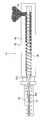
- an extrusion molding apparatus 1 includes a screw-type extruder 2, an extrusion die 10 and a molding die 15 that are detachably attached to the screw-type extruder 2, and the extruder 2, an extrusion die 10 mounted in front of the extrusion direction 2, a breaker plate 12 detachably provided on the extrusion die 10, and a core 20 detachably provided on the molding die 15.
- the screw-type extruder 2 melts a mixture raw material 25, for example, a mixture of wood powder, resin, pigment, and reinforcing agent, which is a raw material of woody synthetic powder, and after gelling and kneading, cooling, crushing, and sizing
- the raw material pellets 26a and the foaming agent 26b, and, if necessary, blended with other additives at a predetermined blending ratio are heated and kneaded to be melt-plasticized, and the screw 5 for extruding the melt-plasticized molding dough 25a. It is an extruder provided with.
- the extrusion molding apparatus 1 according to the present invention is applied to a single-screw type screw-type extruder 2 has been described.
- the present invention may be applied to various screw type extruders such as a mold extruder.
- a single screw type screw type extruder 2 (hereinafter referred to as “extruder 2”) includes a barrel 3, a screw 5 rotatably provided in the barrel 3, a speed reducer that rotationally drives the screw 5, A drive source (not shown) composed of a motor or the like is provided, and an extrusion die 10 and a molding die 15 described later are detachably attached to the distal end side (forward in the extrusion direction, left side in FIG. 1) of the barrel 3.
- the barrel 3 has a cylindrical shape in which the front end in the extruding direction is opened and the rear end (rear in the extruding direction, rightward in FIG. 1) is closed, and a hopper that penetrates the inside and outside of the barrel 3 above the rear end. 4 is provided, and a mixed raw material 25 which is a mixture of raw material pellets 26 a made of wood synthetic powder and a foaming agent 26 b is supplied into the barrel 3 through the hopper 4.
- a heating means such as a band heater is provided on the outer periphery of the barrel 3 so as to wind or wrap the barrel 3 over the entire length of the barrel 3.
- the mixed raw material 25 supplied to is heated.
- the overall length of the barrel 3 is divided into a plurality of zones (for example, a supply zone, a compression zone, and a metering zone), and the temperature can be individually controlled for each zone by a heating means.
- the screw 5 includes a round bar-shaped rotary shaft 5a that is rotatably provided at the center of the barrel 3, and a screw portion 5b that is integrally provided spirally around the rotary shaft 5a.
- the rotary shaft 5a has a rear end (right side in FIG. 1) protruding rearward from the rear end of the barrel 3, and the protruding portion is connected to a drive source. By the operation of the drive source, the rotary shaft 5a and the screw portion 5b are connected. And are integrally driven to rotate.
- the part located in the barrel 3 of the screw 5 includes a supply unit 6 that supplies the mixed raw material 25 arranged on the right side in FIG. 1 and a supply unit 6 that is arranged on the left side in FIG. From the compression unit 7 for heating and kneading the supplied mixed raw material 25 and compressing, and the measuring unit 8 for measuring the mixed raw material 25 supplied from the compression unit 7 arranged on the left side of the compression unit 7 in FIG. It is configured.
- the mixed raw material 25 supplied from the hopper 4 into the barrel 3 is heated and kneaded by the cooperation of the supply unit 6, the compression unit 7 and the measuring unit 8 of the screw 5. While being pushed, it is pumped in the direction of the tip of the screw 5 along the groove 5c between the screw portions 5b of the screw 5 to form a molded material 25a in a melt-plasticized state. It is pushed out of the barrel 3 from the tip.
- the extrusion die 10 rectifies the molded fabric 25a extruded from the tip of the screw 5 and gives a desired cross-sectional shape to the molded fabric 25a. Is attached.
- a rectifying unit 10 a that rectifies and feeds the molding dough 25 a to the breaker plate 12 to be described later is fitted and mounted.
- the rectifying unit 10a has a corresponding outer peripheral small-diameter portion 10c that is fitted into a concave portion 12c of the breaker plate 12 to be described later, and is integrally formed with the large-diameter portion 10b.
- the extrusion die 10 is configured to have a cross-sectional shape in which the volume gradually decreases from the inlet portion 11a of the extrusion die 10 to the rectifying portion outlet 10d in the forward direction of extrusion, and the widthwise dimension of the rectifying portion 10a is described later.
- the length of the plurality of slits 12d (121d to 121d) opened in the bottom surface is substantially the same as the length in the width direction of the inlet 12e, and the height direction of the rectifying unit outlet 10d is formed to be the same as the height of the inlet 12e. (FIGS. 3B and 3C).
- the inlet 11a of the extrusion die 10 communicates with the opening at the tip of the barrel 3, and the outlet 11b is provided with an extrusion hole 11 that communicates with the inlet 15a of the molding die 15 described later. Then, the molding dough 25a pushed out from the tip of the screw 5 is pushed out to the molding die 15 described later.
- the extrusion hole 11 of the extrusion die 10 is formed so that the volume is reduced to a cross-sectional shape (in the present embodiment, a cross-sectional trapezoidal shape) gradually narrowed from the barrel 3 toward the forming die 15.
- the breaker plate 12 is attached to the 11 outlet portions 11b.
- the breaker plate 12 has a disk shape in which the peripheral surface is formed in two stages of a small diameter portion 12a and a large diameter portion 12b. 2 is attached to the front end side of the barrel 3 so that the front side of the extrusion direction (the front side of the paper surface in the figure) is arranged in the direction of the molding die 15 described later.
- a circular recess 12c having a predetermined depth is provided at the center of the breaker plate 12 in the rear side in the extrusion direction (FIG. 3 (A) right).
- a plurality of meshes, holes or slits 12d (eight slits 12d in the present embodiment) penetrating in the extrusion direction reaching the bottom surface of the recess 12c and the surface of the breaker plate 12 (the left side in the middle of FIG. 3A) (, 121d) is provided, and the molding dough 25a pushed out from the screw 5 through the plurality of slits 12d is pushed out to the forming die 15.
- the forming dough 25a pushed out from the screw 5 is fed to the breaker plate 12. Is rectified by the rectification unit 10a of the extrusion die 10 into the recess 12c of the extrusion die 10 and guided to the slits 12d. It is then issued.
- Each slit 12d gradually decreases in volume from the inlet 12e opening at the bottom surface of the recess 12c of the breaker plate 12 communicating with the rectifying unit outlet 10d of the extrusion die 10 toward the outlet 11b of the extrusion port 11 forward in the extrusion direction.
- These slits 12d are applied to the breaker plate 12 with a back pressure in the direction of the screw 5 at the rear of the molding dough extruding direction, and foamed in the molding dough 25a melt-plasticized in the barrel 3. It functions as the volume reduction part 13 which suppresses that the agent 26b foams and gasifies.
- the six slits 12d excluding the two slits 121d and 121d at both ends of the eight slits 12d are inclined surfaces on the upper and lower surfaces in FIG. 3A and vertical surfaces on both sides in FIG.
- the two slits 121d and 121d at both ends have a substantially rectangular cross section with the upper and lower surfaces in FIG. 3A being inclined surfaces and the left or right surface in FIG. It is formed in a flat trapezoidal shape.
- the breaker plate 12 In the peripheral portion of the breaker plate 12, there are provided a plurality of insertion holes 12f penetrating in the front-rear direction of the molding dough extrusion direction, and the breaker plate 12 is attached to the extrusion die 10 by bolts or the like using the plurality of insertion holes 12f.
- the outlet 11b of the extrusion hole 11 is detachably attached.
- reference numeral 14 denotes a pin, which is inserted into a pin hole provided in the end wall of the extrusion die 10 of the breaker plate 12 to position a relative mounting position thereof. It is a member. 12g is a pin hole provided in the breaker plate 12, and the pin 10e of the rectification
- the breaker plate 12 is provided with the eight slits 12d (12d, 121d) as described above, but may be provided with eight or less slits or nine or more slits.
- each slit is formed in a trapezoidal cross section, but the shape is not limited to a trapezoidal cross section, and any shape may be used as long as the volume gradually decreases from the rear in the extrusion direction to the front in the extrusion direction.
- the hole is not limited to a slit, and may be a circular hole or an elliptical hole whose volume gradually decreases in the above direction.
- the molding die 15 further rectifies the molding dough 25a extruded through the breaker plate 12 at the outlet 11b of the extrusion hole 11 of the extrusion die 10 and gives a desired cross-sectional shape. As shown in FIG. 1, it is detachably attached to the outlet portion 11b of the extrusion hole 11 of the extrusion die 10 by a bolt or the like.
- the forming die 15 is attached to the outlet portion 11b of the extrusion hole 11 of the extrusion die 10 so that the inlet portion 15a communicates with the outlet portion 11b of the extrusion hole 11 of the extrusion die 10.
- a molding chamber 15c having the same rectangular cross section is provided inside the molding die 15, and the molding material 25a extruded from the extrusion die 10 through the breaker plate 12 is guided into the molding chamber 15c.
- the cloth 25a is formed into a desired cross-sectional shape, in the present embodiment, like the forming chamber 15c, and is formed into a flat plate shape having the same rectangular cross section.
- the inlet portion 15a of the molding die 15 is formed in a rectangular cross-sectional shape that communicates with the breaker plate 12 provided in the outlet portion 11b of the extrusion hole 11 of the extrusion die 10 in the extrusion direction, and is continuous with the inlet portion 15a.
- a molding chamber 15c having a rectangular cross-sectional shape having a vertical dimension substantially the same as that of the inlet portion 15a and a horizontal dimension larger than that of the inlet portion 15a is formed inside the molding die 15, and is opposed to the outlet portion 15b of the molding chamber 15c.
- a take-up machine 35 to be described later is provided.
- heating means 16 comprising a heater or the like is provided so as to surround the inlet portion 15a, and the heating means 16 supplies the extrusion die 10 to the inlet portion 15a of the molding die 15.
- the molding dough 25a is heated, and the forming dough 25a is maintained in a desired melt plasticized state.
- cooling means 17 comprising a cooling pipe or the like for circulating a cooling medium so as to surround the molding chamber 15c, and the molding means pushed into the molding chamber 15c by the cooling means 17
- the dough 25a is cooled and molded into a foam molded product that matches the cross-sectional shape of the molding chamber 15c.
- a core 20 is provided at the inlet portion 15 a of the core forming die 15.
- the core 20 includes a flat plate-like main body portion 21 having a cross-sectional shape that matches the cross-sectional shape of the inlet portion 15a of the forming die 15, a restriction portion 22 provided in the main body portion 21, and an introduction portion 23 in the illustrated embodiment. , And a fixing portion 24 that is provided integrally with the main body portion 21 and fixes the main body portion 21 to the inlet portion 15a of the molding die 15 (FIG. 9).
- a recess 21a having a rectangular cross section with a predetermined depth is provided behind the main body 21 in the extrusion direction.
- the bottom surface of the recess 21a includes the bottom of the recess 21a and the front of the main body 21 in the extrusion direction.
- a plurality of holes 21b penetrating therethrough are provided, and the concave portion 21a constitutes an introduction portion 23 for introducing the molding fabric 25a from the extrusion die 10, and the molding fabric supplied from the introduction portion 23 by the plurality of holes 21b.
- a limiting portion 22 is provided that applies pressure again to 25a and applies back pressure in the direction of the extrusion die 10.
- the plurality of holes 21b of the restriction portion 22 are arranged in three rows in the thickness direction of the main body portion 21, and a plurality of holes 21b (21c, 21c, 21d) are arranged at equal intervals in each row in the horizontal direction. Is provided.
- each hole 21d in the middle stage is provided on the same vertical line, and each of the upper hole 21c and the lower hole 21c positioned in the front and back direction of the paper surface is adjacent to the holes 21c and 21c.
- the middle stage is formed with 18 holes and the upper and lower stages are 17 holes so as to be disposed between the middle holes 21d (FIG. 7).
- the several hole 21b is provided in the main-body part 21 in 3 steps
- a slit may be provided instead of the hole, and the limiting portion 22 may be configured by a plurality of slits.
- the fixing portion 24 has a cylindrical shape, and is provided integrally with the central portion of the upper and lower side surfaces of the main body portion 21 and the both sides thereof, and is provided integrally with the main body portion so as to correspond to the fixing portion 24 on the upper surface.
- the fixing portion 24 is integrally provided on the center portion of the right edge portion of the lower surface of the lower surface 21 and on both sides thereof, and is fitted into a fixing hole (not shown) formed in the inlet portion 15a of the molding die 15.
- the main body portion 21 is fixed to the inlet portion 15 a of the molding die 15.
- the main body portion 21 is formed in a flat plate shape.
- the main body portion 21 has a circular shape, an elliptical shape, or a semicircular shape according to the cross-sectional shape of the inlet portion 15a of the forming die 15. It can be formed in various shapes such as.
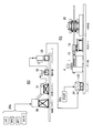
- the extrusion molding apparatus 1 having the above-described configuration is a foamed wood synthetic molding for processing a blend of the raw material pellets 26a and the foaming agent continuously to the woody synthetic powder production line 40 which is the raw material pellets 26a.
- the product manufacturing line 60 is incorporated into the line shown in FIG.
- This wood synthetic powder production line 40 comprises a melting mixer 30, a cooling mixer 31, a granulator 32, and a buffer tank 33.
- a foamed wood synthetic product production line 60 comprises a blender 34, The extrusion molding apparatus 1 according to the present embodiment and the take-up machine 35 are arranged in that order.
- the raw material pellet 26a is produced in the woody synthetic powder production line 40 in the present embodiment.
- wood powder, resin, pigment, reinforcing agent, and the like which are raw materials for wood synthetic powder, are charged into the melting mixer 30 at a predetermined blending ratio, melted and mixed, and the raw material 25 melted and mixed by the melting mixer 30 is cooled by the cooling mixer 31.
- the raw material pellets 26a are made of a woody synthetic powder which is cooled in the cooling mixer 31 and pulverized in a granulator 32 to a predetermined particle size, and is adjusted to a predetermined particle size in the granulator 32.
- Stock in the buffer tank 33 is provided to a predetermined blending ratio, melted and mixed, and the raw material 25 melted and mixed by the melting mixer 30 is cooled by the cooling mixer 31.
- the raw material pellets 26a are made of a woody synthetic powder which is cooled in the cooling mixer 31 and pulverized in a granulator 32 to a predetermined particle size, and is adjusted to a predetermined particle size in the granulator 32.
- the raw material pellet 26a is charged from the buffer tank 33 to the blender 34 (tilting cylinder mixer, etc.) of the foamed wood synthetic molded product manufacturing line 60, and the foaming agent 26b is charged to the blender 34 from another system.
- 26b is dry blended at a predetermined blending ratio and prepared as a mixed raw material 25, which is supplied to the extrusion molding apparatus 1 of the present embodiment.
- wood powder 50 to 200 ⁇ m: 51 to 53%, resin (thermoplastic resin) (random polypropylene; 18 to 20%, HDPE; 25%) , Pigment (iron oxide type); 3%, reinforcing agent (maleic acid-modified polypropylene); 0.5%, and foaming agent (inorganic foaming agent master patch); .
- resin thermoplastic resin
- Pigment random polypropylene
- Pigment iron oxide type
- reinforcing agent maleic acid-modified polypropylene
- foaming agent inorganic foaming agent master patch
- the resin may be homopolypropylene, block polypropylene, or polypropylene
- the reinforcing agent may be metablene (trade name, Mitsubishi Rayon Co., Ltd.), an additive that increases the melt viscosity and melt tension of the resin.
- a foaming agent MB3064 (manufactured by Sankyo Kasei Co., Ltd.) or Polyslen EE405F (manufactured by Eiwa Kasei Kogyo Co., Ltd.) may be used.
- the mixed raw material 25 is supplied through the hopper 4 into the barrel 3 of the extruder 2 of the extrusion molding apparatus 1, and the screw 5 is driven to rotate by the operation of the drive source. 4, the mixed raw material 25 is supplied into the barrel 3, and the tip of the screw 5 is moved along the groove 5 c of the screw portion 5 b of the screw 5 while heating and kneading the mixed raw material 25 by the cooperation of the heating means and the screw 5. A pressing force is applied in the direction and the pressure is fed to form a molded material 25a that is melt-plasticized.
- the melt-plasticized molding dough 25a is extruded from the tip of the screw 5 into the extrusion hole 11 of the extrusion die 10, and is formed on the molding die 15 through the plurality of slits 12d of the breaker plate 12 at the outlet portion 11b of the extrusion hole 11.
- the molding dough 25a extruded from the tip of the screw 5 into the extrusion hole 11 of the extrusion die 10 is guided to the breaker plate 12 of the outlet portion 11b through the extrusion hole 11 and is behind the breaker plate 12 in the extrusion direction. From the inside of the recess 12c, it is guided to the plurality of slits 12d of the volume reducing portion 13 and pushed out to the inlet portion 15a of the forming die 15 through the plurality of slits 12d. A back pressure is applied to the inside of the barrel 3, and the pressure inside the barrel 3 is increased.
- the foaming agent 26b contained in the molding dough 25a is suppressed from foaming inside the barrel 3 and inside the extrusion hole 11 of the extrusion die 10, and the molding dough 25a having a stable property is supplied from the extrusion die 10 to the forming die 15. can do.
- the molding dough 25a pushed out to the inlet portion 15a of the molding die 15 through the plurality of slits 12d of the breaker plate 12 is guided to the main body portion 21 of the core 20 provided at the inlet portion 15a of the molding die 15. Then, it is led from the introduction part 23 formed of the concave part 21a of the main body part 21 to the plurality of holes 21b of the restriction part 22, and is pushed out into the molding chamber 15c of the molding die 15 through the plurality of holes 21b.
- the molding dough 25a in which foaming of the foaming agent 26b is suppressed between the main body portion 21 of the core 20 and the breaker plate 12 passes through the plurality of holes 21b of the limiting portion 22 of the main body portion 21 of the core 20.
- the pushing force of the extruded dough is limited between the core 20 and the breaker plate 12 located behind the forming dough 25a of the core 20 in the pushing direction.
- the pressure is increased again, and the molding dough 25a in a state where the pressure is increased is pushed out into the forming chamber 15c, and the pressure is relatively released in the forming chamber 15c, so that the forming dough 25a is formed in the entire forming chamber 15c. Evenly distributed.
- the molding dough 25a is pushed into the molding chamber 15c through the plurality of holes 21b arranged uniformly in the main body 21, so that the pressure of the molding dough 25a is relatively released in the molding chamber 15c.
- the foaming agent is foamed, the bubbles are dispersed substantially uniformly throughout the foamed molded product molded in the molding chamber 15c.
- the bubbles are concentrated on the core (center) of the foam molded product molded in the molding chamber 15c, and the desired undispersed air bubbles are uniformly dispersed throughout without generating the internal gap G.
- a foamed molded article having the same strength as the foamed product is obtained.
- the molding dough 25a pushed into the molding chamber 15c is pushed into the molding chamber 15c in a state where the pressure is increased, the extrusion speed of the molding dough 25a into the molding chamber 15c can be increased.
- the molding speed of foam molded products can be increased, and production efficiency can be greatly increased.
- the mixed raw material 25 is a mixture of wood powder, thermoplastic resin, pigment, reinforcing agent, and foaming agent, but is not limited to this, and includes other various foaming agents.
- the present invention may be applied to material extrusion.
Landscapes
- Engineering & Computer Science (AREA)
- Mechanical Engineering (AREA)
- Extrusion Moulding Of Plastics Or The Like (AREA)
- Molding Of Porous Articles (AREA)
Abstract
Description
図1~図9に,本発明による押出成形装置の一実施の形態を示す。
前記スクリュー型押出機2は,混合原料25,例えば,木質合成粉の原料である木粉,樹脂,顔料,強化剤の混合物を溶融し,ゲル化混練した後,冷却,破砕,整粒して成る原料ペレット26a及び発泡剤26b,並びに必要に応じて他の添加剤を所定の配合比で配合したものを加熱混練して溶融可塑化し,この溶融可塑化した成形生地25aを押し出すスクリュー5を備える押出機である。
押出ダイ10は,スクリュー5の先端から押し出された成形生地25aを整流すると共に,成形生地25aに所望の断面形状を付与するものであって,バレル3の先端側にボルト等によって着脱可能に取り付けられている。
ブレーカープレート12は,図2~図5に示すように,周面が小径部12aと大径部12bの2段に形成される円板状をなすものであって,押出方向後方(図2の紙面裏面側)がスクリュー5方向に配置され,押出方向前方(同図紙面表面側)が後述する成形ダイ15方向に配置されるように,バレル3の先端側に取り付けられている。
成形ダイ15は,押出ダイ10の押出孔11の出口部11bのブレーカープレート12を介して押し出された成形生地25aを更に整流すると共に,所望の断面形状を付与するものであって,図1に示すように,押出ダイ10の押出孔11の出口部11bにボルト等によって着脱自在に取り付けられている。
成形ダイ15の入口部15aには中子20が設けられている。
原料ペレット
この木質合成粉製造ライン40は,溶融ミキサー30と,冷却ミキサー31と,整粒機32と,バッファタンク33とから成り,発泡木質合成成形品製造ライン60は,ブレンダー34と,本実施の形態による押出成形装置1と,引取機35とをそれらの順に配置したものである。

そして,図1に示すように,押出成形装置1の押出機2のバレル3内にホッパ4を介して混合原料25を供給し,駆動源の作動によってスクリュー5を回転駆動させ,ホッパ4からバレル3内に混合原料25を供給し,加熱手段の作動とスクリュー5との協働により,混合原料25を加熱混練しながらスクリュー5のスクリュー部5bの溝5cに沿ってスクリュー5の先端方向に押出力を加えて圧送し,溶融可塑化した成形生地25aに形成する。
2 スクリュー型押出機
3 バレル
4 ホッパ
5 スクリュー
5a 回転軸
5b スクリュー部
5c 溝
6 供給部
7 圧縮部
8 計量部
10 押出ダイ
10a 整流部
10b 大径部
10c 小径部
10d 整流部出口
10e ピン
11 押出孔
11a 入口部
11b 出口部
12 ブレーカープレート
12a 小径部
12b 大径部
12c 凹部
12d,121d スリット
12e 導入口
12f 挿孔
12g ピン孔
13 減容部
14 位置決め用のピン
15 成形ダイ
15a 入口部
15b 出口部
15c 成形室
16 加熱手段
17 冷却手段
20 中子
21 本体部
21a 凹部
21b,21c,21d 孔
22 制限部
23 導入部
24 固定部
25 混合原料
25a 成形生地
26a 原料ペレット
26b 発泡剤
30 溶融ミキサー
31 冷却ミキサー
32 整粒機
33 バッファタンク
34 ブレンダー
35 引取機
40 木質合成粉製造ライン
41 押出成形装置
42 スクリュー型押出機
43 バレル
44 ホッパ
45 スクリュー
50 ダイ
50a 成形室
52 ブレーカープレート
60 発泡(木質合成)成形品製造ライン
G (内部)空隙
Claims (6)
- 少なくとも発泡剤を含む混合原料を加熱混練して溶融可塑化した成形生地とし,該成形生地をスクリューの先端から押し出す押出機と,前記スクリューの先端側に装着される押出ダイと,該押出ダイの出口に装着される成形ダイとを備えた押出成形装置であって,
前記押出ダイの出口部に,前記スクリューの先端から押し出された成形生地に対して押出し力に抗する抑制力を加え,前記スクリュー方向に背圧を付与するブレーカープレートを設けると共に,前記成形ダイの入口部に,前記押出ダイから押し出された成形生地に対して押出し力に抗する抑制力を加え,前記押出ダイの出口部との空間に背圧を付与する中子を設けたことを特徴とする押出成形装置。 - 前記ブレーカープレートは,前記スクリュー方向から前記成形ダイ方向に徐々に容積が減少する複数のスリットないし孔からなる減容部を有し,該減容部の複数のスリットないし孔により,前記スクリュー方向に背圧が付与されることを特徴とする請求項1に記載の押出成形装置。
- 前記中子は,前記押出ダイ方向から前記成形ダイ方向に徐々に容積が減少する複数のスリットないし孔からなる制限部を有し,該制限部の複数のスリットないし孔により,前記押出ダイ方向の出口部間の成形生地に背圧が付与されることを特徴とする請求項1又は2に記載の押出成形装置。
- 前記中子は,前記成形ダイの入口部の断面形状に合致した断面形状の本体部を有し,該本体部の全体に亘って前記制限部の複数のスリットないし孔が設けられていることを特徴とする請求項3に記載の押出成形装置。
- 前記中子の本体部には,前記押出ダイから押し出された成形生地を導入する導入部が設けられ,該導入部に前記制限部の複数の孔又は複数のスリットが連通していることを特徴とする請求項4に記載の押出成形装置。
- 前記混合原料は,木質合成粉の原料である木粉,熱可塑性樹脂,顔料及び強化剤を溶融混練,冷却,整粒して成る原料ペレットに,発泡剤を混合して成ることを特徴とする請求項1~5いずれか1項記載の押出成形装置。
Priority Applications (8)
| Application Number | Priority Date | Filing Date | Title |
|---|---|---|---|
| JP2010514347A JP4981967B2 (ja) | 2008-05-26 | 2009-05-19 | 押出成形装置 |
| MX2010012785A MX2010012785A (es) | 2008-05-26 | 2009-05-19 | Aparato de extrusion. |
| CA2726172A CA2726172C (en) | 2008-05-26 | 2009-05-19 | Extrusion apparatus |
| RU2010146210/05A RU2478478C2 (ru) | 2008-05-26 | 2009-05-19 | Экструзионная машина |
| EP09754396.1A EP2298532A4 (en) | 2008-05-26 | 2009-05-19 | EXTRUSION UNIT |
| CN2009801188903A CN102036801B (zh) | 2008-05-26 | 2009-05-19 | 挤压成型装置 |
| BRPI0909593A BRPI0909593A2 (pt) | 2008-05-26 | 2009-05-19 | aparelho de extrusão |
| AU2009252630A AU2009252630B2 (en) | 2008-05-26 | 2009-05-19 | Extrusion apparatus |
Applications Claiming Priority (2)
| Application Number | Priority Date | Filing Date | Title |
|---|---|---|---|
| JP2008-137248 | 2008-05-26 | ||
| JP2008137248 | 2008-05-26 |
Publications (1)
| Publication Number | Publication Date |
|---|---|
| WO2009144887A1 true WO2009144887A1 (ja) | 2009-12-03 |
Family
ID=41376777
Family Applications (1)
| Application Number | Title | Priority Date | Filing Date |
|---|---|---|---|
| PCT/JP2009/002198 Ceased WO2009144887A1 (ja) | 2008-05-26 | 2009-05-19 | 押出成形装置 |
Country Status (11)
| Country | Link |
|---|---|
| EP (1) | EP2298532A4 (ja) |
| JP (1) | JP4981967B2 (ja) |
| KR (1) | KR101009364B1 (ja) |
| CN (1) | CN102036801B (ja) |
| AU (1) | AU2009252630B2 (ja) |
| BR (1) | BRPI0909593A2 (ja) |
| CA (1) | CA2726172C (ja) |
| MX (1) | MX2010012785A (ja) |
| MY (1) | MY159653A (ja) |
| RU (1) | RU2478478C2 (ja) |
| WO (1) | WO2009144887A1 (ja) |
Cited By (4)
| Publication number | Priority date | Publication date | Assignee | Title |
|---|---|---|---|---|
| WO2011135745A1 (ja) * | 2010-04-28 | 2011-11-03 | Wpcコーポレーション株式会社 | 押出成形用複合ペレットの製造方法,及び前記方法で製造された押出成形用の複合ペレット |
| WO2011136273A1 (ja) * | 2010-04-28 | 2011-11-03 | Wpcコーポレーション株式会社 | 押出成形用複合ペレットの製造方法,及び前記方法で製造された押出成形用の複合ペレット |
| CN102975378A (zh) * | 2012-12-10 | 2013-03-20 | 南充市富康塑胶制品厂 | 阻燃牵线管 |
| CN110815771A (zh) * | 2019-09-25 | 2020-02-21 | 浙江天之元物流科技有限公司 | 双拼气泡袋生产工艺 |
Families Citing this family (10)
| Publication number | Priority date | Publication date | Assignee | Title |
|---|---|---|---|---|
| JP5624534B2 (ja) * | 2011-12-20 | 2014-11-12 | Wpcコーポレーション株式会社 | 木質合成粉 |
| CN102653129A (zh) * | 2012-05-21 | 2012-09-05 | 贵州大学 | 螺杆挤出机机头的压力调节方法及装置 |
| WO2015152175A1 (ja) * | 2014-03-31 | 2015-10-08 | 東レ株式会社 | 液晶性ポリエステル樹脂ペレットの製造装置および製造方法 |
| CN103964693B (zh) * | 2014-04-23 | 2017-03-29 | 宁波荣山新型材料有限公司 | 一种低温泡沫玻璃保温材料的膨化成型一体化工艺 |
| CN105538583A (zh) * | 2016-02-19 | 2016-05-04 | 孙清涛 | 一种多边连续成型发泡机 |
| US11712826B2 (en) * | 2019-07-09 | 2023-08-01 | Otrajet Inc. | Injection molding system and injection molding method |
| KR102411815B1 (ko) * | 2021-07-14 | 2022-06-22 | 주식회사 에스텍 | 오일 추출기 |
| CN116039040B (zh) * | 2022-12-29 | 2023-07-21 | 金华小飞鱼玩具股份有限公司 | 一种塑料制品的挤压成型设备及其成型工艺 |
| KR102693125B1 (ko) * | 2024-01-24 | 2024-08-08 | (주) 미라이후손관거 | 압출기용 브레이커 플레이트 |
| KR102911816B1 (ko) * | 2024-06-11 | 2026-01-13 | 에이치에스엠(주) | 티-다이 오리피스 |
Citations (4)
| Publication number | Priority date | Publication date | Assignee | Title |
|---|---|---|---|---|
| JPS5483969A (en) * | 1977-12-16 | 1979-07-04 | Sekisui Plastics | Method of making foam based on polypropylene |
| JPH08118452A (ja) | 1994-10-24 | 1996-05-14 | Ain Eng Kk | 中空樹脂成形板の押出成形方法及び装置 |
| JP2001019787A (ja) * | 1999-07-05 | 2001-01-23 | Sekisui Plastics Co Ltd | 板状スチレン系樹脂発泡体の製造方法 |
| JP2002273778A (ja) | 2001-03-19 | 2002-09-25 | Sekisui Chem Co Ltd | ブレーカープレートおよびシート状成形品の製造方法 |
Family Cites Families (15)
| Publication number | Priority date | Publication date | Assignee | Title |
|---|---|---|---|---|
| CA931720A (en) * | 1969-08-07 | 1973-08-14 | Hayashi Motoshige | Synthetic wood and a method for preparation thereof |
| JPS534229Y2 (ja) * | 1972-03-07 | 1978-02-02 | ||
| JP3456709B2 (ja) * | 1991-05-17 | 2003-10-14 | 日立造船株式会社 | 多軸押出機 |
| DE4325514C1 (de) * | 1993-07-29 | 1994-10-27 | Schaaf Technologie Gmbh | Kochextruder zur Herstellung von thermisch behandelten Biopolymeren sowie Verfahren zum Kochextrudieren von Biopolymeren |
| JP3404169B2 (ja) * | 1995-03-17 | 2003-05-06 | 株式会社神戸製鋼所 | 押出機用ブレーカプレート |
| JPH09109228A (ja) * | 1995-10-19 | 1997-04-28 | Beishin Kogyo Kk | 発泡合成樹脂成形品の発泡促進方法 |
| JPH10272670A (ja) * | 1997-03-28 | 1998-10-13 | Beishin Kogyo Kk | 発泡合成樹脂成形品の発泡促進方法 |
| US6524420B1 (en) * | 1999-05-28 | 2003-02-25 | General Electric | Composite and process for making |
| JP2001026043A (ja) | 1999-07-14 | 2001-01-30 | Sumitomo Wiring Syst Ltd | 押出機のノズル構造 |
| JP2001273778A (ja) * | 2000-03-27 | 2001-10-05 | Seiko Epson Corp | メモリデバイスおよびその製造方法、並びにメモリデバイス記録方法 |
| JP3667655B2 (ja) * | 2001-04-25 | 2005-07-06 | 株式会社ジェイエスピー | 押出発泡複合体の製造装置 |
| WO2003016014A1 (en) * | 2001-08-16 | 2003-02-27 | Ispa, Inc. | Extrusion composite compression injection process and apparatus |
| JP2004314371A (ja) * | 2003-04-15 | 2004-11-11 | Kiriyama Kasei:Kk | 木質樹脂成形体及びその押出成形法 |
| JP2005238554A (ja) * | 2004-02-25 | 2005-09-08 | Misawa Homes Co Ltd | 押出発泡成形方法および押出発泡成形装置 |
| RU2314918C1 (ru) * | 2006-06-29 | 2008-01-20 | Закрытое Акционерное Общество "Юнайтед Бейкерс" | Экструдер |
-
2008
- 2008-09-25 KR KR1020080094226A patent/KR101009364B1/ko not_active Expired - Fee Related
-
2009
- 2009-05-19 AU AU2009252630A patent/AU2009252630B2/en not_active Ceased
- 2009-05-19 CA CA2726172A patent/CA2726172C/en not_active Expired - Fee Related
- 2009-05-19 MY MYPI2010005290A patent/MY159653A/en unknown
- 2009-05-19 CN CN2009801188903A patent/CN102036801B/zh not_active Expired - Fee Related
- 2009-05-19 JP JP2010514347A patent/JP4981967B2/ja not_active Expired - Fee Related
- 2009-05-19 MX MX2010012785A patent/MX2010012785A/es active IP Right Grant
- 2009-05-19 WO PCT/JP2009/002198 patent/WO2009144887A1/ja not_active Ceased
- 2009-05-19 RU RU2010146210/05A patent/RU2478478C2/ru not_active IP Right Cessation
- 2009-05-19 BR BRPI0909593A patent/BRPI0909593A2/pt not_active IP Right Cessation
- 2009-05-19 EP EP09754396.1A patent/EP2298532A4/en not_active Withdrawn
Patent Citations (4)
| Publication number | Priority date | Publication date | Assignee | Title |
|---|---|---|---|---|
| JPS5483969A (en) * | 1977-12-16 | 1979-07-04 | Sekisui Plastics | Method of making foam based on polypropylene |
| JPH08118452A (ja) | 1994-10-24 | 1996-05-14 | Ain Eng Kk | 中空樹脂成形板の押出成形方法及び装置 |
| JP2001019787A (ja) * | 1999-07-05 | 2001-01-23 | Sekisui Plastics Co Ltd | 板状スチレン系樹脂発泡体の製造方法 |
| JP2002273778A (ja) | 2001-03-19 | 2002-09-25 | Sekisui Chem Co Ltd | ブレーカープレートおよびシート状成形品の製造方法 |
Non-Patent Citations (1)
| Title |
|---|
| See also references of EP2298532A4 |
Cited By (6)
| Publication number | Priority date | Publication date | Assignee | Title |
|---|---|---|---|---|
| WO2011135745A1 (ja) * | 2010-04-28 | 2011-11-03 | Wpcコーポレーション株式会社 | 押出成形用複合ペレットの製造方法,及び前記方法で製造された押出成形用の複合ペレット |
| WO2011136273A1 (ja) * | 2010-04-28 | 2011-11-03 | Wpcコーポレーション株式会社 | 押出成形用複合ペレットの製造方法,及び前記方法で製造された押出成形用の複合ペレット |
| JP2011230419A (ja) * | 2010-04-28 | 2011-11-17 | Wpc Corporation Kk | 押出成形用複合ペレットの製造方法,及び前記方法で製造された押出成形用の複合ペレット |
| US8871345B2 (en) | 2010-04-28 | 2014-10-28 | Wpc Corporation | Method for producing composite pellet for extrusion molding, and composite pellet for extrusion molding produced by the method |
| CN102975378A (zh) * | 2012-12-10 | 2013-03-20 | 南充市富康塑胶制品厂 | 阻燃牵线管 |
| CN110815771A (zh) * | 2019-09-25 | 2020-02-21 | 浙江天之元物流科技有限公司 | 双拼气泡袋生产工艺 |
Also Published As
| Publication number | Publication date |
|---|---|
| KR20090122869A (ko) | 2009-12-01 |
| CA2726172C (en) | 2014-07-22 |
| MY159653A (en) | 2017-01-13 |
| AU2009252630A1 (en) | 2009-12-03 |
| BRPI0909593A2 (pt) | 2015-11-17 |
| CA2726172A1 (en) | 2009-12-03 |
| RU2010146210A (ru) | 2012-07-10 |
| AU2009252630B2 (en) | 2012-06-28 |
| MX2010012785A (es) | 2010-12-21 |
| EP2298532A4 (en) | 2014-07-30 |
| CN102036801A (zh) | 2011-04-27 |
| JP4981967B2 (ja) | 2012-07-25 |
| RU2478478C2 (ru) | 2013-04-10 |
| EP2298532A1 (en) | 2011-03-23 |
| KR101009364B1 (ko) | 2011-01-19 |
| JPWO2009144887A1 (ja) | 2011-10-06 |
| CN102036801B (zh) | 2013-08-21 |
Similar Documents
| Publication | Publication Date | Title |
|---|---|---|
| JP4981967B2 (ja) | 押出成形装置 | |
| CN102470597B (zh) | 挤出发泡成形用成形材料及其制造方法、使用所述成形材料制造的木质发泡成形体以及所述木质发泡成形体的制造方法和制造装置 | |
| CN101657308A (zh) | 使用再利用毯废料的木材-塑料复合材料及其生产系统和方法 | |
| JP5457933B2 (ja) | 押出成形用複合ペレットの製造方法,及び前記方法で製造された押出成形用の複合ペレット | |
| JP7164170B2 (ja) | コンクリート型枠用せき板の押出成形方法及びコンクリート型枠用せき板の押出成形装置 | |
| CN108715019A (zh) | 一种内充气式挤出发泡装置及成型方法 | |
| JP5507939B2 (ja) | 押出成形装置 | |
| JP6621149B2 (ja) | コンクリート型枠用せき板の押出成形方法及びコンクリート型枠用せき板の押出成形装置 | |
| CN109049602A (zh) | 一种用于生产淀粉基塑料的单螺杆挤出机 | |
| KR100818342B1 (ko) | 합성수지 패널의 이중 압출 성형장치 | |
| JPH08118452A (ja) | 中空樹脂成形板の押出成形方法及び装置 | |
| JP2000351105A (ja) | 中空樹脂成形板の押出成形方法及び装置 | |
| JP4254626B2 (ja) | 射出成形機の射出装置および発泡射出成形方法 | |
| CN202357423U (zh) | 一种用于双螺杆发泡挤出机内的螺杆 | |
| JPH11277664A (ja) | 木粉入り熱可塑性樹脂製発泡体およびその製造方法 | |
| HK1152508A (en) | Extrusion apparatus | |
| JP3533083B2 (ja) | 木質系材料入り熱可塑性樹脂製ボードの製造方法 | |
| HK1166758B (en) | Molding material for extrusion foam molding, process for producing same, woody molded foam produced from the molding material, and process and apparatus for producing the woody molded foam | |
| HK1176910A (en) | Method for producing composite pellet for extrusion molding, and composite pellet for extrusion molding produced by the method | |
| JPS5848333B2 (ja) | センイホキヨウネツカソセイジユシバンジヨウタイ ノ セイゾウホウホウ |
Legal Events
| Date | Code | Title | Description |
|---|---|---|---|
| WWE | Wipo information: entry into national phase |
Ref document number: 200980118890.3 Country of ref document: CN |
|
| 121 | Ep: the epo has been informed by wipo that ep was designated in this application |
Ref document number: 09754396 Country of ref document: EP Kind code of ref document: A1 |
|
| WWE | Wipo information: entry into national phase |
Ref document number: 4216/KOLNP/2010 Country of ref document: IN |
|
| WWE | Wipo information: entry into national phase |
Ref document number: 2009252630 Country of ref document: AU |
|
| WWE | Wipo information: entry into national phase |
Ref document number: 2010514347 Country of ref document: JP |
|
| WWE | Wipo information: entry into national phase |
Ref document number: 2009754396 Country of ref document: EP |
|
| WWE | Wipo information: entry into national phase |
Ref document number: MX/A/2010/012785 Country of ref document: MX |
|
| WWE | Wipo information: entry into national phase |
Ref document number: 2726172 Country of ref document: CA |
|
| NENP | Non-entry into the national phase |
Ref country code: DE |
|
| ENP | Entry into the national phase |
Ref document number: 2009252630 Country of ref document: AU Date of ref document: 20090519 Kind code of ref document: A |
|
| WWE | Wipo information: entry into national phase |
Ref document number: 2010146210 Country of ref document: RU |
|
| ENP | Entry into the national phase |
Ref document number: PI0909593 Country of ref document: BR Kind code of ref document: A2 Effective date: 20101125 |