WO2009144915A1 - 半導体装置およびその製造方法 - Google Patents
半導体装置およびその製造方法 Download PDFInfo
- Publication number
- WO2009144915A1 WO2009144915A1 PCT/JP2009/002308 JP2009002308W WO2009144915A1 WO 2009144915 A1 WO2009144915 A1 WO 2009144915A1 JP 2009002308 W JP2009002308 W JP 2009002308W WO 2009144915 A1 WO2009144915 A1 WO 2009144915A1
- Authority
- WO
- WIPO (PCT)
- Prior art keywords
- region
- semiconductor layer
- thin film
- semiconductor
- crystalline
- Prior art date
- Legal status (The legal status is an assumption and is not a legal conclusion. Google has not performed a legal analysis and makes no representation as to the accuracy of the status listed.)
- Ceased
Links
Images


Classifications
-
- H—ELECTRICITY
- H10—SEMICONDUCTOR DEVICES; ELECTRIC SOLID-STATE DEVICES NOT OTHERWISE PROVIDED FOR
- H10D—INORGANIC ELECTRIC SEMICONDUCTOR DEVICES
- H10D8/00—Diodes
-
- H—ELECTRICITY
- H10—SEMICONDUCTOR DEVICES; ELECTRIC SOLID-STATE DEVICES NOT OTHERWISE PROVIDED FOR
- H10D—INORGANIC ELECTRIC SEMICONDUCTOR DEVICES
- H10D62/00—Semiconductor bodies, or regions thereof, of devices having potential barriers
- H10D62/40—Crystalline structures
- H10D62/405—Orientations of crystalline planes
-
- H—ELECTRICITY
- H10—SEMICONDUCTOR DEVICES; ELECTRIC SOLID-STATE DEVICES NOT OTHERWISE PROVIDED FOR
- H10D—INORGANIC ELECTRIC SEMICONDUCTOR DEVICES
- H10D86/00—Integrated devices formed in or on insulating or conducting substrates, e.g. formed in silicon-on-insulator [SOI] substrates or on stainless steel or glass substrates
- H10D86/01—Manufacture or treatment
- H10D86/021—Manufacture or treatment of multiple TFTs
- H10D86/0221—Manufacture or treatment of multiple TFTs comprising manufacture, treatment or patterning of TFT semiconductor bodies
- H10D86/0223—Manufacture or treatment of multiple TFTs comprising manufacture, treatment or patterning of TFT semiconductor bodies comprising crystallisation of amorphous, microcrystalline or polycrystalline semiconductor materials
- H10D86/0225—Manufacture or treatment of multiple TFTs comprising manufacture, treatment or patterning of TFT semiconductor bodies comprising crystallisation of amorphous, microcrystalline or polycrystalline semiconductor materials using crystallisation-promoting species, e.g. using a Ni catalyst
-
- H—ELECTRICITY
- H10—SEMICONDUCTOR DEVICES; ELECTRIC SOLID-STATE DEVICES NOT OTHERWISE PROVIDED FOR
- H10D—INORGANIC ELECTRIC SEMICONDUCTOR DEVICES
- H10D86/00—Integrated devices formed in or on insulating or conducting substrates, e.g. formed in silicon-on-insulator [SOI] substrates or on stainless steel or glass substrates
- H10D86/40—Integrated devices formed in or on insulating or conducting substrates, e.g. formed in silicon-on-insulator [SOI] substrates or on stainless steel or glass substrates characterised by multiple TFTs
- H10D86/411—Integrated devices formed in or on insulating or conducting substrates, e.g. formed in silicon-on-insulator [SOI] substrates or on stainless steel or glass substrates characterised by multiple TFTs characterised by materials, geometry or structure of the substrates
-
- H—ELECTRICITY
- H10—SEMICONDUCTOR DEVICES; ELECTRIC SOLID-STATE DEVICES NOT OTHERWISE PROVIDED FOR
- H10D—INORGANIC ELECTRIC SEMICONDUCTOR DEVICES
- H10D86/00—Integrated devices formed in or on insulating or conducting substrates, e.g. formed in silicon-on-insulator [SOI] substrates or on stainless steel or glass substrates
- H10D86/40—Integrated devices formed in or on insulating or conducting substrates, e.g. formed in silicon-on-insulator [SOI] substrates or on stainless steel or glass substrates characterised by multiple TFTs
- H10D86/421—Integrated devices formed in or on insulating or conducting substrates, e.g. formed in silicon-on-insulator [SOI] substrates or on stainless steel or glass substrates characterised by multiple TFTs having a particular composition, shape or crystalline structure of the active layer
- H10D86/425—Integrated devices formed in or on insulating or conducting substrates, e.g. formed in silicon-on-insulator [SOI] substrates or on stainless steel or glass substrates characterised by multiple TFTs having a particular composition, shape or crystalline structure of the active layer having different crystal properties in different TFTs or within an individual TFT
-
- H—ELECTRICITY
- H10—SEMICONDUCTOR DEVICES; ELECTRIC SOLID-STATE DEVICES NOT OTHERWISE PROVIDED FOR
- H10D—INORGANIC ELECTRIC SEMICONDUCTOR DEVICES
- H10D86/00—Integrated devices formed in or on insulating or conducting substrates, e.g. formed in silicon-on-insulator [SOI] substrates or on stainless steel or glass substrates
- H10D86/40—Integrated devices formed in or on insulating or conducting substrates, e.g. formed in silicon-on-insulator [SOI] substrates or on stainless steel or glass substrates characterised by multiple TFTs
- H10D86/60—Integrated devices formed in or on insulating or conducting substrates, e.g. formed in silicon-on-insulator [SOI] substrates or on stainless steel or glass substrates characterised by multiple TFTs wherein the TFTs are in active matrices
-
- G—PHYSICS
- G02—OPTICS
- G02F—OPTICAL DEVICES OR ARRANGEMENTS FOR THE CONTROL OF LIGHT BY MODIFICATION OF THE OPTICAL PROPERTIES OF THE MEDIA OF THE ELEMENTS INVOLVED THEREIN; NON-LINEAR OPTICS; FREQUENCY-CHANGING OF LIGHT; OPTICAL LOGIC ELEMENTS; OPTICAL ANALOGUE/DIGITAL CONVERTERS
- G02F1/00—Devices or arrangements for the control of the intensity, colour, phase, polarisation or direction of light arriving from an independent light source, e.g. switching, gating or modulating; Non-linear optics
- G02F1/01—Devices or arrangements for the control of the intensity, colour, phase, polarisation or direction of light arriving from an independent light source, e.g. switching, gating or modulating; Non-linear optics for the control of the intensity, phase, polarisation or colour
- G02F1/13—Devices or arrangements for the control of the intensity, colour, phase, polarisation or direction of light arriving from an independent light source, e.g. switching, gating or modulating; Non-linear optics for the control of the intensity, phase, polarisation or colour based on liquid crystals, e.g. single liquid crystal display cells
- G02F1/133—Constructional arrangements; Operation of liquid crystal cells; Circuit arrangements
- G02F1/1333—Constructional arrangements; Manufacturing methods
- G02F1/1345—Conductors connecting electrodes to cell terminals
- G02F1/13454—Drivers integrated on the active matrix substrate
-
- G—PHYSICS
- G02—OPTICS
- G02F—OPTICAL DEVICES OR ARRANGEMENTS FOR THE CONTROL OF LIGHT BY MODIFICATION OF THE OPTICAL PROPERTIES OF THE MEDIA OF THE ELEMENTS INVOLVED THEREIN; NON-LINEAR OPTICS; FREQUENCY-CHANGING OF LIGHT; OPTICAL LOGIC ELEMENTS; OPTICAL ANALOGUE/DIGITAL CONVERTERS
- G02F2201/00—Constructional arrangements not provided for in groups G02F1/00 - G02F7/00
- G02F2201/58—Arrangements comprising a monitoring photodetector
-
- H—ELECTRICITY
- H10—SEMICONDUCTOR DEVICES; ELECTRIC SOLID-STATE DEVICES NOT OTHERWISE PROVIDED FOR
- H10D—INORGANIC ELECTRIC SEMICONDUCTOR DEVICES
- H10D30/00—Field-effect transistors [FET]
- H10D30/60—Insulated-gate field-effect transistors [IGFET]
- H10D30/67—Thin-film transistors [TFT]
- H10D30/6704—Thin-film transistors [TFT] having supplementary regions or layers in the thin films or in the insulated bulk substrates for controlling properties of the device
- H10D30/6713—Thin-film transistors [TFT] having supplementary regions or layers in the thin films or in the insulated bulk substrates for controlling properties of the device characterised by the properties of the source or drain regions, e.g. compositions or sectional shapes
- H10D30/6715—Thin-film transistors [TFT] having supplementary regions or layers in the thin films or in the insulated bulk substrates for controlling properties of the device characterised by the properties of the source or drain regions, e.g. compositions or sectional shapes characterised by the doping profiles, e.g. having lightly-doped source or drain extensions
-
- H—ELECTRICITY
- H10—SEMICONDUCTOR DEVICES; ELECTRIC SOLID-STATE DEVICES NOT OTHERWISE PROVIDED FOR
- H10D—INORGANIC ELECTRIC SEMICONDUCTOR DEVICES
- H10D30/00—Field-effect transistors [FET]
- H10D30/60—Insulated-gate field-effect transistors [IGFET]
- H10D30/67—Thin-film transistors [TFT]
- H10D30/6704—Thin-film transistors [TFT] having supplementary regions or layers in the thin films or in the insulated bulk substrates for controlling properties of the device
- H10D30/6723—Thin-film transistors [TFT] having supplementary regions or layers in the thin films or in the insulated bulk substrates for controlling properties of the device having light shields
-
- H—ELECTRICITY
- H10—SEMICONDUCTOR DEVICES; ELECTRIC SOLID-STATE DEVICES NOT OTHERWISE PROVIDED FOR
- H10K—ORGANIC ELECTRIC SOLID-STATE DEVICES
- H10K59/00—Integrated devices, or assemblies of multiple devices, comprising at least one organic light-emitting element covered by group H10K50/00
- H10K59/10—OLED displays
- H10K59/12—Active-matrix OLED [AMOLED] displays
- H10K59/13—Active-matrix OLED [AMOLED] displays comprising photosensors that control luminance
-
- H—ELECTRICITY
- H10—SEMICONDUCTOR DEVICES; ELECTRIC SOLID-STATE DEVICES NOT OTHERWISE PROVIDED FOR
- H10P—GENERIC PROCESSES OR APPARATUS FOR THE MANUFACTURE OR TREATMENT OF DEVICES COVERED BY CLASS H10
- H10P14/00—Formation of materials, e.g. in the shape of layers or pillars
- H10P14/20—Formation of materials, e.g. in the shape of layers or pillars of semiconductor materials
- H10P14/34—Deposited materials, e.g. layers
- H10P14/3402—Deposited materials, e.g. layers characterised by the chemical composition
- H10P14/3404—Deposited materials, e.g. layers characterised by the chemical composition being Group IVA materials
- H10P14/3411—Silicon, silicon germanium or germanium
-
- H—ELECTRICITY
- H10—SEMICONDUCTOR DEVICES; ELECTRIC SOLID-STATE DEVICES NOT OTHERWISE PROVIDED FOR
- H10P—GENERIC PROCESSES OR APPARATUS FOR THE MANUFACTURE OR TREATMENT OF DEVICES COVERED BY CLASS H10
- H10P14/00—Formation of materials, e.g. in the shape of layers or pillars
- H10P14/20—Formation of materials, e.g. in the shape of layers or pillars of semiconductor materials
- H10P14/38—Formation of materials, e.g. in the shape of layers or pillars of semiconductor materials characterised by treatments done after the formation of the materials
- H10P14/3802—Crystallisation or recrystallisation of non-monocrystalline semiconductor materials, e.g. regrowth
- H10P14/3806—Crystallisation or recrystallisation of non-monocrystalline semiconductor materials, e.g. regrowth using crystallisation-enhancing elements
-
- H—ELECTRICITY
- H10—SEMICONDUCTOR DEVICES; ELECTRIC SOLID-STATE DEVICES NOT OTHERWISE PROVIDED FOR
- H10P—GENERIC PROCESSES OR APPARATUS FOR THE MANUFACTURE OR TREATMENT OF DEVICES COVERED BY CLASS H10
- H10P14/00—Formation of materials, e.g. in the shape of layers or pillars
- H10P14/20—Formation of materials, e.g. in the shape of layers or pillars of semiconductor materials
- H10P14/38—Formation of materials, e.g. in the shape of layers or pillars of semiconductor materials characterised by treatments done after the formation of the materials
- H10P14/3802—Crystallisation or recrystallisation of non-monocrystalline semiconductor materials, e.g. regrowth
- H10P14/3808—Crystallisation or recrystallisation of non-monocrystalline semiconductor materials, e.g. regrowth using laser beams
Definitions
- the present invention relates to a semiconductor device including a thin film transistor (TFT) and a thin film diode (TFD) and a manufacturing method thereof.
- TFT thin film transistor
- TFD thin film diode
- TFT thin film transistor
- TFD thin film diode
- the device characteristics of TFTs and TFDs formed on the same substrate are most affected by the crystallinity of the semiconductor layer serving as the active region.
- a method for obtaining a good crystalline semiconductor layer on a glass substrate a method of crystallizing an amorphous semiconductor film by irradiating a laser beam is generally used.
- crystallization is performed by heat treatment.
- the obtained crystalline semiconductor film may be irradiated with laser light in order to further improve the crystallinity.
- a good semiconductor film having a uniform crystal orientation can be obtained by a low-temperature, short-time heat treatment as compared with a conventional crystalline semiconductor film crystallized only by laser irradiation.
- Patent Document 1 discloses an image sensor including an optical sensor unit using TFD and a drive circuit using TFT on the same substrate.
- an amorphous semiconductor film formed on a substrate is crystallized to form TFT and TFD semiconductor layers.
- the TFT and the TFD are integrally formed on the same substrate, not only the semiconductor device can be miniaturized, but also a great cost merit such as a reduction in the number of parts can be obtained. Further, it is possible to realize a product with a new function that cannot be obtained by combining conventional parts.
- a TFT (crystalline silicon TFT) using crystalline silicon and a TFD (amorphous silicon TFD) using amorphous silicon are formed on the same substrate using the same semiconductor film (silicon film).
- a catalytic element that promotes crystallization of amorphous silicon is added only to a region where an active region of a TFT is to be formed in an amorphous silicon film formed on a substrate. Thereafter, by performing heat treatment, only a region where an active region of the TFT is to be formed is crystallized, and a silicon film in which a region to be a TFD is in an amorphous state is formed.
- this silicon film is used, the crystalline silicon TFT and the amorphous silicon TFD can be easily manufactured on the same substrate.
- Patent Document 2 a part of the same amorphous semiconductor film is crystallized, a crystalline silicon TFT is formed from the crystallized part, and an amorphous part is left from the amorphous part.
- the characteristics of the crystalline silicon TFT can be improved by controlling the crystallization conditions, but the characteristics of the amorphous silicon TFD cannot be sufficiently improved.
- hydrogen contained in the original amorphous silicon is lost in the process of crystallizing a part of the amorphous silicon film into crystalline silicon. This is because an electrically good amorphous silicon TFD cannot be produced.
- the present invention has been made in view of the above problems, and its purpose is to optimize TFT and TFD semiconductor layers formed by crystallizing the same amorphous semiconductor film according to the respective device characteristics. There is to do.
- the semiconductor device includes a semiconductor layer including a channel region, a source region, and a drain region, a gate electrode that controls conductivity of the channel region, and a gate insulation provided between the semiconductor layer and the gate electrode.
- the semiconductor layer of the diode does not substantially contain the catalytic element.
- the semiconductor layer of the thin film diode is mainly configured with a plane orientation that is a (100) plane and / or a (111) plane of the crystal.
- the thin film diode includes an intrinsic region located between the n-type region and the p-type region in the semiconductor layer of the thin film diode, and the intrinsic region is a (100) plane of a crystal. Alternatively, and / or mainly with a plane orientation that becomes the (111) plane.
- At least the channel region of the semiconductor layer of the thin film transistor is mainly configured with a plane orientation in which a ⁇ 111> crystal zone plane of the crystal is oriented.
- At least the channel region of the semiconductor layer of the thin film transistor is mainly configured with a plane orientation that is a (110) plane and / or a (211) plane of crystal.
- At least the channel region in the semiconductor layer of the thin film transistor is composed of a collection of columnar crystals, and the growth direction of each columnar crystal is substantially parallel to the carrier movement direction in the thin film transistor.
- the catalyst element may not be precipitated but may be contained in a solid solution state.
- the concentration of the catalytic element in the source region or the drain region of the semiconductor layer of the thin film transistor may be higher than the concentration of the catalytic element in the channel region.
- the thin film transistor has a gettering region formed in a region other than the channel region, the source region, and the drain region in the semiconductor layer of the thin film transistor, and the concentration of the catalytic element in the gettering region is the channel region, It may be higher than the concentration of the catalytic element in the source region and the drain region.
- the thin film transistor may be a plurality of thin film transistors including an n-channel thin film transistor and a p-channel thin film transistor.
- the catalyst element may be nickel.
- the method of manufacturing a semiconductor device includes (a) a step of preparing a substrate having an amorphous semiconductor film formed on the surface, and (b) promoting crystallization only to a part of the amorphous semiconductor film. (C) a heat treatment is performed on the amorphous semiconductor film to which the catalytic element is selectively added, and a part of the amorphous semiconductor film is crystallized.
- a crystalline semiconductor comprising a high crystalline region formed by further crystallizing or recrystallizing a use crystallized region, and a low crystalline region formed by crystallizing the amorphous region Obtaining a film; and (e) patterning the crystalline semiconductor film.
- the first island-shaped semiconductor layer includes the high crystalline region
- the second island-shaped semiconductor layer includes the step of including the low crystalline region
- a portion of the amorphous semiconductor film to which the catalytic element is added is crystallized to form the catalytic crystallization region.
- the step (c) includes the step (c1) of crystallizing a portion of the amorphous semiconductor film to which the catalytic element is added to form a first catalyst-based crystallization region; (C2) forming a second catalyst utilization crystallization region by laterally growing crystals from the first catalyst utilization crystallization region to the periphery thereof, wherein the step (d) comprises using the first catalyst utilization.
- the crystallized region is further crystallized or recrystallized to form a first highly crystalline region, and the second catalyst-utilized crystallized region is crystallized or recrystallized to form a second highly crystalline region.
- the step (e) may include a step of forming a region that later becomes a channel region of a thin film transistor in the first island-shaped semiconductor layer, using the highly crystalline region of the crystalline semiconductor film.
- the step (e) may include a step of forming a region that later becomes an intrinsic region of a thin film diode in the second island-shaped semiconductor layer using the low crystalline region of the crystalline semiconductor film.
- the step (e) may be a step of forming the entire first island-shaped semiconductor layer using the highly crystalline region of the crystalline semiconductor film.
- the step (e) may be a step of forming the entire second island-shaped semiconductor layer using the low crystalline region of the crystalline semiconductor film.
- the step (e) uses the first highly crystalline region of the crystalline semiconductor film to form at least one of the first island-like semiconductor layers that will later become the source region and / or drain region of the thin film transistor. Forming a region and forming a region to be a channel region of a thin film transistor later in the first island-shaped semiconductor layer by using the second highly crystalline region.
- the step (e) may further include a step of forming a semiconductor layer that later becomes one electrode of a capacitor using the low crystalline region of the crystalline semiconductor film.
- the step (e) may further include a step of forming an island-like semiconductor layer that later becomes an active region of another thin film transistor by using the low crystalline region of the crystalline semiconductor film.
- the step (b) includes a step of forming a mask having an opening on the amorphous semiconductor film, and a selected region of the amorphous semiconductor film through the opening. Adding the catalyst element.
- the laser light is irradiated at an irradiation energy density that does not completely reset the crystal state of the catalyst-based crystallization region before the laser light irradiation and can crystallize the amorphous region. It is preferable that the process to include is included.
- the substrate has a light-transmitting property, and before the step (a), a portion of the substrate which is to be a lower portion of a region where a second island-shaped semiconductor layer to be an active region of a thin film diode is formed later. You may further include the process of forming the light shielding layer for light-shielding the light from the back surface of the said board
- (f) at least a step of forming a gate insulating film on the first island-shaped semiconductor layer; and (g) on the gate insulating film on the first island-shaped semiconductor layer.
- At least the channel region of the semiconductor layer of the thin film transistor is subjected to heat treatment by adding a catalytic element that functions to promote crystallization of the amorphous semiconductor film. It is a crystalline region crystallized by this.
- the semiconductor layer of the thin film diode is preferably a crystalline region crystallized without using the catalyst element.
- the semiconductor layer of the thin film diode may be a crystalline semiconductor layer crystallized by irradiating the amorphous semiconductor film with laser light.
- the semiconductor layer of the thin film transistor is composed of columnar crystals, and the semiconductor layer of the thin film diode is substantially free of columnar crystals.
- the semiconductor layer of the thin film transistor may include continuous grain boundary crystalline silicon (CG silicon), and the semiconductor layer of the thin film diode may include polycrystalline silicon.
- CG silicon continuous grain boundary crystalline silicon
- the semiconductor layer of the thin film diode may include polycrystalline silicon.
- the semiconductor layer of the thin film transistor is further crystallized or crystallized by irradiating a laser beam after crystallizing the amorphous semiconductor film by adding the catalytic element and performing a heat treatment.
- a recrystallized high crystalline region is included, and at least the channel region of the semiconductor layer of the thin film transistor is formed in the high crystalline region.
- an n-type impurity element is doped in a region to be a source region and a drain region later in the first island-shaped semiconductor layer.
- the step (h) and the step (i) are performed simultaneously.
- the step (h) includes a step of doping the first island-shaped semiconductor layer with a p-type impurity element in a region that will later become a source region and a drain region, and the step (h) and the step (J) may be performed simultaneously.
- the first island-like semiconductor layer is a plurality of island-like semiconductor layers including an island-like semiconductor layer that later becomes an active region of an n-channel thin film transistor and an island-like semiconductor layer that later becomes an active region of a p-channel thin film transistor.
- the step (h) includes a step (h1) of doping an island-shaped semiconductor layer to be an n-channel thin film transistor later in the first island-shaped semiconductor layer with an n-type impurity element; A step (h2) of doping an island-shaped semiconductor layer to be a channel thin film transistor with a p-type impurity element, wherein the step (h1) is performed simultaneously with the step (i), and the step (h2) includes It may be performed simultaneously with the step (j).
- Another semiconductor device of the present invention is a semiconductor device manufactured by any one of the methods described above.
- the electronic apparatus of the present invention includes any one of the above semiconductor devices.
- the electronic device of the present invention may include a display unit or an optical sensor unit. Moreover, you may provide the display part and the optical sensor part.
- the display unit may include the thin film transistor, and the optical sensor unit may include the thin film diode.
- the optical sensor unit may be an ambient sensor for adjusting the luminance of the display unit. Or the touch panel sensor of the said display part may be sufficient.
- the display device of the present invention is a display device including a display region having a plurality of display units and a frame region located around the display region, further including an optical sensor unit including a thin film diode, and each display
- the portion includes an electrode and a thin film transistor connected to the electrode, and the thin film transistor and the thin film diode are formed on the same substrate, and the thin film transistor includes a channel region, a source region, and a drain region.
- a thin film diode including an n-type region, a p-type region, a gate electrode for controlling conductivity of the channel region, and a gate insulating film provided between the semiconductor layer and the gate electrode.
- the Aode semiconductor layer is a crystalline semiconductor layer formed by crystallizing the same amorphous semiconductor film, and the semiconductor layer of the thin film transistor functions to promote crystallization of the amorphous semiconductor film. And the semiconductor layer of the thin film diode does not substantially contain the catalyst element.
- the other crystalline semiconductor layer does not substantially contain the catalytic element.
- the other crystalline semiconductor layer may be connected to a source region or a drain region of the semiconductor layer of the thin film transistor.
- Another display device of the present invention is a display device comprising a display region having a plurality of display units and a frame region located around the display region, further comprising an optical sensor unit including a thin film diode, Each display unit includes an electrode and a first thin film transistor connected to the electrode, and the frame region includes a second thin film transistor constituting a driving circuit, the first and second thin film transistors,
- the thin film diode is formed on the same substrate, and the first and second thin film transistors include a semiconductor layer including a channel region, a source region, and a drain region, and a gate electrode that controls conductivity of the channel region.
- a gate insulating film provided between the semiconductor layer and the gate electrode, the thin film diode comprising an n-type region, a p-type region, and an n-type region
- a semiconductor layer including an intrinsic region provided between the region and the p-type region, and the semiconductor layer of the first and second thin film transistors and the semiconductor layer of the thin film diode are formed by crystallizing the same amorphous semiconductor film.
- Still another display device of the present invention is a display device including a display region having a plurality of display units and a frame region located around the display region, and further includes an optical sensor unit including a thin film diode.
- Each display portion includes an electrode and a first thin film transistor connected to the electrode, and the frame region includes a second thin film transistor constituting a driving circuit, and the first and second thin film transistors;
- the thin film diode is formed on the same substrate, and the first and second thin film transistors include a semiconductor layer including a channel region, a source region, and a drain region, and a gate for controlling conductivity of the channel region.
- An electrode, and a gate insulating film provided between the semiconductor layer and the gate electrode.
- the thin film diode includes an n-type region, a p-type region, and a semiconductor layer including an intrinsic region provided between an n-type region and a p-type region, wherein the semiconductor layer of the first and second thin film transistors and the semiconductor layer of the thin film diode are the same amorphous semiconductor; A crystalline semiconductor layer formed by crystallizing the film, wherein the semiconductor layer of the second thin film transistor includes a catalytic element having a function of promoting crystallization of the amorphous semiconductor film; The thin film transistor and the semiconductor layer of the thin film diode substantially do not contain the catalytic element.
- the drive circuit configured by the second thin film transistor may be a drive circuit that drives the first thin film transistor connected to each display unit.
- the drive circuit configured by the second thin film transistor may be a drive circuit that drives an optical sensor unit including the thin film diode.
- the substrate has translucency
- the thin film diode further includes a light shielding layer disposed between a semiconductor layer of the thin film diode and the substrate, and the light shielding layer is viewed from the back surface of the substrate.
- the thin film diode is preferably formed so as to overlap with at least the intrinsic region in the semiconductor layer.
- the display device may further include a backlight.
- a plurality of the optical sensor units may be provided, and each of the plurality of optical sensor units may be disposed in the display area corresponding to each display unit or a set of two or more display units.
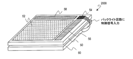
- the backlight has a backlight control circuit that adjusts the luminance of light emitted from the backlight, and the optical sensor unit is disposed in the frame area and generates an illuminance signal based on the illuminance of external light. Then, it may be output to the backlight control circuit.
- the TFT and TFD semiconductor layers are optimized according to the device characteristics required for each, so that good characteristics are obtained.
- a semiconductor device including a TFT and a TFD having the above can be provided.
- the present invention can be suitably used for a liquid crystal display device with a sensor function.
- a liquid crystal display device including a TFT used for a driving circuit and a TFT for switching a pixel electrode and a TFD used as a photosensor, a high field effect mobility and a low threshold voltage are obtained.
- a TFT having a low dark current value and a TFD having a high SN ratio to light (a current value ratio in light and dark) can be formed using the same amorphous semiconductor film.
- by optimizing the crystal state in the channel region that greatly affects the field effect mobility of the TFT and the intrinsic region that greatly affects the photosensitivity of the TFD it is possible to obtain the optimum device characteristics for each semiconductor device. Can do.
- a high-performance semiconductor device including a TFT and a TFD formed on the same substrate can be manufactured without increasing the manufacturing process and manufacturing cost, and the product can be made compact, high-performance, low Cost can be reduced.
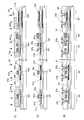
- FIG. 1 is a schematic cross-sectional view of a semiconductor device according to a first embodiment of the present invention.
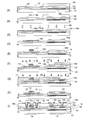
- (A) to (I) are schematic process cross-sectional views showing the manufacturing process of the semiconductor device of the first embodiment according to the present invention.
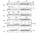
- (A) to (F) are schematic process cross-sectional views showing the manufacturing process of the semiconductor device of the second embodiment according to the present invention.
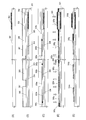
- (A) to (E) are schematic process cross-sectional views illustrating the manufacturing process of the semiconductor device of the third embodiment according to the present invention.
- (F) to (H) are schematic process cross-sectional views showing the manufacturing process of the semiconductor device of the third embodiment according to the present invention.
- (I) to (K) are schematic process cross-sectional views showing the manufacturing process of the semiconductor device of the third embodiment according to the present invention.
- FIG. 1 A) to (E) are schematic process cross-sectional views showing the manufacturing process of the semiconductor device of the fourth embodiment according to the present invention.
- FIG. 1 A) to (E) are schematic process cross-sectional views illustrating the manufacturing process of the semiconductor device of the fifth embodiment according to the present invention.
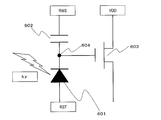
- It is a circuit diagram of optical sensor TFD.
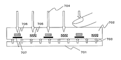
- It is a block diagram of an optical sensor type touch panel.
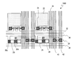
- It is a typical top view which illustrates the back substrate in the liquid crystal display of a touch panel type of a 6th embodiment by the present invention.
- It is a perspective view which illustrates the liquid crystal display device with an ambient light sensor of 6th Embodiment by this invention.
- (A) to (C) are diagrams showing characteristics of dark current, bright current, and light-to-dark ratio in the optical sensor TFD.
- the semiconductor device of this embodiment includes a thin film transistor and a thin film diode.
- the thin film transistor includes a semiconductor layer including a channel region, a source region, and a drain region, a gate insulating film provided over the semiconductor layer, and a gate electrode that controls conductivity of the channel region.
- the thin film diode includes a semiconductor layer including at least an n-type region and a p-type region.
- the semiconductor layer of the thin film transistor and the semiconductor layer of the thin film diode are crystalline semiconductor layers obtained by crystallizing the same amorphous semiconductor film.
- the semiconductor layer of the thin film transistor includes a catalytic element that functions to promote crystallization of the amorphous semiconductor film.
- the semiconductor layer of the thin film diode does not substantially contain a catalytic element.
- the semiconductor layer of the thin film transistor includes a crystallization region crystallized using a catalytic element. More specifically, it includes a crystallization region that is crystallized by adding a metal element (catalyst element) having an action of promoting crystallization to the amorphous semiconductor film and then performing heat treatment.
- a crystallization region is made of continuous grain boundary crystalline silicon (CG silicon) in which the orientation directions of crystal grains are aligned.
- the size of the crystal domain (substantially the same plane orientation region) of CG silicon is about 2 ⁇ m or more and about 8 ⁇ m or less, and the average of polycrystalline silicon (Low Temperature Poly-Silicon: LPS) film produced by ordinary laser crystallization Since it is larger than the crystal grain size (typically about 200 nm) and the orientation of the crystal grains is high, it has excellent electrical characteristics (for example, high mobility).
- LPS Low Temperature Poly-Silicon
- the semiconductor layer of the thin film diode includes a crystalline region crystallized by a method not using a catalytic element.
- the amorphous semiconductor film is a crystalline semiconductor layer crystallized by irradiating laser light, and is made of the above-mentioned polycrystalline silicon (LPS), and the average crystal grain size is, for example, 50 nm or more and 500 nm or less. .
- LPS polycrystalline silicon
- the semiconductor layer of the thin film diode includes an intrinsic region located between the n-type region and the p-type region, and the intrinsic region substantially does not include a catalytic element.
- the semiconductor layer of the thin film diode includes an intrinsic region located between the n-type region and the p-type region, and the intrinsic region is crystallized by irradiating the amorphous semiconductor film with laser light. A crystalline semiconductor layer.
- each of the TFT and the TFD can realize the optimum element characteristics for the element.
- a crystalline semiconductor layer formed using the same amorphous semiconductor film is used, a semiconductor device including the above-described TFT and TFD on the same substrate can be obtained by a simple method.
- a simple element configuration can be realized.
- a crystalline semiconductor layer crystallized using a catalytic element has high mobility due to its high crystallinity. Therefore, it is suitable for TFTs that require high field effect mobility and low threshold voltage, such as those used in driver circuits. Furthermore, generally, the higher the crystallinity of the semiconductor layer, the lower the leakage current during the TFT off operation, and the higher the ON / OFF ratio. That is, it is also suitable as a TFT for switching the pixel electrode. Similarly, the same can be said for TFD, and the higher the crystallinity, the higher the current value in the forward direction. Even when a reverse bias is applied to the TFD to make it OFF, the leakage current value is considered to decrease with higher crystallinity.
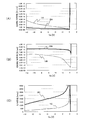
- the inventors of the present invention have characteristics of a crystalline semiconductor layer crystallized by heat treatment using a catalytic element and a crystalline semiconductor layer crystallized without using a catalytic element for the same amorphous semiconductor film. Were compared, and the results as shown in FIGS. 13A to 13C were obtained.
- FIG. 13A is a graph showing the dependence of dark current on the anode voltage Va applied to the TFD.
- the horizontal axis is the anode voltage Va, and a negative value indicates a reverse bias with respect to the TFD.
- the vertical axis is the dark current, and shows the current value per unit width normalized to the width W of the TFD semiconductor layer.
- 1A shows the characteristics of the semiconductor layer crystallized using the catalytic element
- 2A shows the characteristics of the semiconductor layer crystallized without using the catalytic element.
- FIG. 13B is a graph showing the Va dependency of the bright current.
- the horizontal axis represents the anode voltage Va applied to the TFD
- the vertical axis represents the bright current when 10000 lux light is irradiated.
- the bright current indicates a current value per unit width normalized with respect to the width W of the TFD semiconductor layer, as in the graph shown in FIG. 1B shows the characteristics of the semiconductor layer crystallized using the catalyst element, and 2B shows the characteristics of the semiconductor layer crystallized without using the catalyst element.
- FIG. 13C is a graph showing the dependency of Va on the vertical axis as the S / N ratio of the bright current / dark current ratio of these semiconductor layers.
- 1C indicates the characteristics of the semiconductor layer crystallized using the catalytic element
- 2C indicates the characteristics of the semiconductor layer crystallized without using the catalytic element. It can be seen that the semiconductor layer (1C) using the catalytic element has a higher S / N ratio than the semiconductor layer (2C) not using the catalytic element for any region of Va.
- Table 1 shows specific numerical values of the dark current, the bright current, and the S / N ratio with respect to the anode voltage.
- the value of the anode voltage Va applied to the TFD differs depending on the required electronic device.
- the dark current is reduced to about 1/5 in the semiconductor layer crystallized without using the catalytic element, compared to the semiconductor layer crystallized using the catalytic element,
- the bright current increases about 1.3 times, and as a result, the S / N ratio increases about 6 times.
- the dark current is remarkably reduced, and thereby the S / N ratio is greatly improved.
- the catalyst element remaining in the semiconductor layer crystallized using the catalyst element is It is in a solid solution state.
- TFTs have not been adversely affected by the catalytic element in a solid solution state.
- a TFD used as an optical sensor adversely affects characteristics even when a catalytic element in a solid solution state is included in the semiconductor layer. This is because in TFD, it is required to keep the dark current value as small as possible as compared with TFT, so that the influence of the catalytic element on the leakage current appears more strongly than TFT, and it becomes obvious as a demerit.
- a catalytic element is used in a TFT and a TFD that are formed on the same substrate and in which the semiconductor layer is formed by a crystalline semiconductor layer formed by crystallizing the same amorphous semiconductor film.
- a TFT having a high field effect mobility and a low threshold voltage is formed by using a crystallized semiconductor layer, and a TFD used as an optical sensor by using a crystallized semiconductor layer without using a catalytic element. It is possible to form a TFD having a high sensitivity to external light and a high S / N ratio (current value ratio between light and dark).
- the channel region that greatly influences the field effect mobility of the TFT is formed from the region crystallized using the catalytic element, and the intrinsic effect of greatly affecting the photosensitivity of the TFD from the region crystallized without using the catalytic element.
- TFT and TFD semiconductor layers are easily formed by selectively adding a catalytic element to an amorphous semiconductor film, crystallizing only the added region, and leaving the other regions amorphous. Can be divided. After that, the region that remains amorphous may be crystallized by irradiation with laser light. That is, the TFD semiconductor layer or its intrinsic region is preferably a crystalline semiconductor layer obtained by crystallizing an amorphous semiconductor film by irradiating laser light.
- the laser light is also applied to the region crystallized by adding the catalytic element and heat treatment, and the crystallinity of the region can be further improved. That is, as an embodiment, the channel region of the semiconductor layer of the TFT is irradiated with laser light after adding a catalytic element having a function of promoting crystallization of the amorphous semiconductor film and crystallizing by heat treatment. A recrystallized crystalline semiconductor layer is preferred. This eliminates the need for position control to the amorphous region during laser irradiation, and can be performed by a simple method with high productivity.
- a crystalline semiconductor layer composed of a collection of micro columnar crystals can be obtained.
- the direction of columnar crystals can be generally controlled. Therefore, in the TFT semiconductor layer, the channel region is composed of a collection of columnar crystals, and the growth direction of each columnar crystal is made substantially parallel to the carrier moving direction in the thin film transistor, so that a higher current driving capability is achieved. TFT with can be realized.
- At least the channel region of the TFT semiconductor layer is mainly composed of a region where the ⁇ 111> crystal zone plane of the crystal is oriented. Furthermore, in the semiconductor layer of the TFT, it is preferable that at least the channel region is mainly configured with a plane orientation that becomes the (110) plane and / or the (211) plane of the crystal. Specifically, the crystal plane orientation ratio of the crystalline semiconductor layer occupies a region of 50% or more of the (110) plane orientation and (211) plane orientation, among the ⁇ 111> crystal zone planes. It is preferable that
- the film surface of the obtained crystalline semiconductor film is a collection of plane orientations perpendicular to the ⁇ 111> direction.
- the plane orientations with particularly strong orientation are the (110) plane and the (211) plane.
- the ⁇ 111> crystal zone plane has a very high hole mobility compared to other planes, and can particularly improve the performance of a p-channel TFT, which is inferior to an n-channel TFT, and is balanced in a semiconductor circuit using a TFT. There is a merit that it is easy to take.
- the two crystal planes (110) plane and (211) plane have a strong tendency. Therefore, these crystal plane orientations are very suitable plane orientations for constituting a TFT.
- the TFD semiconductor layer is mainly configured with a plane orientation that becomes the (100) plane and / or the (111) plane of the crystal. Further, the TFD semiconductor layer includes an intrinsic region located between the n-type region and the p-type region, and the intrinsic region has a plane orientation that is a (100) plane and / or a (111) plane of the crystal, It is preferable that it is comprised mainly.
- the plane orientation of the crystalline semiconductor film is influenced by the insulator underlying the semiconductor film (particularly in the case of amorphous silicon dioxide) or by the semiconductor layer surface (vacuum interface). Tends to face the (111) plane and / or the (100) plane. In this case, TFD seems to provide high photosensitivity.
- the dark current shown in FIG. 13A greatly depends on the presence or concentration of the catalytic element, but the bright current shown in FIG. 13B tends to affect the crystal orientation.
- optimum element characteristics required for each of the TFT and the TFD can be simultaneously realized by using a semiconductor layer formed by crystallizing the same amorphous semiconductor film.
- the catalyst element in the channel region of the semiconductor layer of the TFT, it is preferable that the catalyst element is not precipitated but is contained in a solid solution state.
- the catalyst element having a concentration exceeding its solid solubility is precipitated in the form of a silicide compound.
- a change to the form of the silicide compound is essential, so that the silicide compound always remains after the crystal growth.
- these silicide compounds have an adverse effect on electrical characteristics in the semiconductor layer of the TFT, in particular, a leakage current at the time of off operation, and thus need to be removed in the final device. Therefore, although the channel region of the semiconductor layer of the TFT of the present invention contains catalytic elements, it is desirable that they are not precipitated but are in a solid solution state.
- the concentration of the catalytic element in the source region or the drain region of the semiconductor layer of the TFT is higher than the concentration of the catalytic element in the channel region.
- the semiconductor layer of the TFT preferably has a gettering region separately from the source region and the drain region, and the catalyst element concentration in the gettering region is preferably higher than the catalyst element concentration in the channel region, the source region, and the drain region. .
- the region used as the gettering region in the manufacturing process is not removed but left after completion of the TFT, so that the action of gettering the catalytic element outside the channel region is not limited to the element in the manufacturing process. It can be obtained continuously after the completion of.
- the catalyst element used for crystallization one or more elements selected from the group consisting of Ni, Co, Sn, Pb, Pd, Fe, and Cu can be used.
- One or more kinds of elements selected from these have the effect of promoting the crystallization of the amorphous semiconductor film in a small amount. Among them, the most remarkable effect can be obtained particularly when Ni is used.
- the thin film transistor in this embodiment may be an n-channel thin film transistor or a p-channel thin film transistor.
- the semiconductor device of this embodiment may include a plurality of thin film transistors including n-channel and p-channel thin film transistors.
- the semiconductor device of the present embodiment may have TFTs and TFDs having other crystal states in addition to the TFTs and TFDs having the respective crystal states described above. For example, some TFTs may be separately formed for a plurality of TFTs, such as using a semiconductor layer crystallized without adding a catalyst element as in TFD.
- This embodiment can be suitably used for electronic devices such as a liquid crystal display device with a sensor function and an organic EL display device.
- electronic devices such as a liquid crystal display device with a sensor function and an organic EL display device.
- a display device having a more compact and higher resolution has been developed by providing a display region including a pixel portion and a driver circuit on the same substrate. Furthermore, the configuration (system-on-panel) in which logic circuits such as a memory circuit and a clock generation circuit are built on the substrate can not only reduce the size and weight of the display device but also reduce the manufacturing cost, and the reliability of the product. It is also possible to improve the sex.
- a TFT is generally used as a switching element, and a TFT is also used in a drive circuit or a logic circuit.
- TFDs are fabricated on the same substrate together with TFTs, and the device characteristics of TFDs that cannot be obtained with TFTs are used.
- an electronic device such as a display device with a sensor function in which an optical sensor is incorporated inside and outside the display area can be considered.
- the optical sensor unit may be an ambient sensor for adjusting the luminance of the display unit, or the optical sensor unit may be a touch panel sensor of the display unit. Also good.
- the optical sensor unit may be an ambient sensor for adjusting the luminance of the display unit, or the optical sensor unit may be a touch panel sensor of the display unit. Also good.
- an electronic device having a display unit and a photosensor unit a high synergistic effect as a product is obtained, and it can be applied to a wide range of applications.
- a TFT used as a switching element in a pixel portion In order to manufacture a display device with a sensor function, it is desirable to form a TFT used as a switching element in a pixel portion, a TFT constituting a driving circuit, and a TFD used as an optical sensor on the same substrate. It is.
- an amorphous semiconductor film is crystallized by a known crystallization method to form a crystalline semiconductor film and a semiconductor layer of TFT and TFD is formed using the crystalline semiconductor film, these elements are formed. Can be formed integrally.
- the same crystalline semiconductor film is used for each semiconductor layer of TFT and TFD, and cannot be optimized according to the characteristics required for each element.
- the display device includes a display region having a plurality of display units, and a frame region located around the display region, and further includes an optical sensor unit including a thin film diode,
- Each display portion includes an electrode and a thin film transistor connected to the electrode.
- the thin film transistor and the thin film diode are formed over the same substrate.
- the thin film transistor includes a semiconductor layer including a channel region, a source region, and a drain region. , A gate electrode for controlling the conductivity of the channel region, and a gate insulating film provided between the semiconductor layer and the gate electrode.
- the thin film diode includes an n-type region, a p-type region, and an n-type region and a p-type region.
- the semiconductor layer including the intrinsic region provided between the mold region and the semiconductor layer of the thin film transistor and the semiconductor layer of the thin film diode are the same amorphous A crystalline semiconductor layer formed by crystallizing a semiconductor film, and at least a channel region of the semiconductor layer of the thin film transistor is added with a catalytic element that promotes crystallization of the amorphous semiconductor film, and heat treatment
- the concentration of the catalytic element in the intrinsic region of the semiconductor layer of the thin film diode is lower than the concentration of the catalytic element in the channel region of the semiconductor layer of the thin film transistor.
- the intrinsic region of the semiconductor layer of the thin film diode substantially does not contain a catalytic element.
- the intrinsic region of the semiconductor layer of the thin film diode is preferably a crystalline semiconductor layer that is crystallized by irradiating the amorphous semiconductor film with laser light.
- the TFT semiconductor layer crystallized by the catalytic element and the TFD semiconductor layer having a lower catalytic element concentration than the TFT semiconductor layer can be formed on the same substrate.
- a pixel switching TFT having a high degree and a TFD for an optical sensor having a high contrast ratio with respect to outside light can be integrally formed. Therefore, a compact display device to which a high-performance sensor function is added while maintaining high display characteristics can be realized.
- a crystalline semiconductor layer serving as an electrode on one side of a capacitor can be formed on the substrate using the same amorphous semiconductor film as the semiconductor layer of the thin film transistor and the semiconductor layer of the thin film diode.
- the concentration of the catalytic element in the semiconductor layer serving as the electrode on one side of the capacitor is lower than the concentration of the catalytic element in the channel region of the semiconductor layer of the thin film transistor.
- the capacitor electrode does not need to have high crystallinity, and may function as an electrode. Rather, there is a concern that the surface shape such as micro etch pits may cause insulation leakage due to insufficient coverage of the insulating film constituting the capacitor.
- the semiconductor layer serving as an electrode on one side of the capacitor may be connected to the source region or the drain region of the semiconductor layer of the thin film transistor.
- the display device includes a display region having a plurality of display units, and a frame region located around the display region, and further includes an optical sensor unit including a thin film diode, and each display The portion has an electrode and a first thin film transistor connected to the electrode, and the frame region has a second thin film transistor that constitutes a drive circuit.
- the first and second thin film transistors and the thin film diode are:
- the first and second thin film transistors formed over the same substrate include a semiconductor layer including a channel region, a source region, and a drain region, a gate electrode that controls conductivity of the channel region, a semiconductor layer, and the gate
- a thin film diode is provided between the n-type region, the p-type region, and the n-type region and the p-type region.
- the semiconductor layer includes an intrinsic region, and the semiconductor layers of the first and second thin film transistors and the semiconductor layer of the thin film diode are crystalline semiconductor layers formed by crystallizing the same amorphous semiconductor film.
- the channel region is crystallized by heat treatment with the addition of a catalytic element having a function of promoting crystallization of the amorphous semiconductor film.
- concentration of the catalytic element in the intrinsic region of the semiconductor layer of the diode is lower than the concentration of the catalytic element in the channel region of the semiconductor layer of the first and second thin film transistors.
- the intrinsic region of the semiconductor layer of the thin film diode substantially does not contain a catalytic element.
- the intrinsic region of the semiconductor layer of the thin film diode is preferably a crystalline semiconductor layer crystallized by irradiating the amorphous semiconductor film with laser light.
- the TFT semiconductor layer crystallized by the catalytic element and the TFD semiconductor layer having a lower catalytic element concentration than the TFT semiconductor layer can be formed on the same substrate. It is possible to integrally form a pixel switching TFT and a peripheral drive circuit TFT having a high degree and a TFD for an optical sensor having a high contrast ratio with respect to external light. Therefore, a compact display device to which a high-performance sensor function is added while maintaining high display characteristics can be realized.
- the display device includes a display region having a plurality of display units and a frame region located around the display region, further including a photosensor unit including a thin film diode, and each display The part has an electrode and a first thin film transistor connected to the electrode, and the frame region has a second thin film transistor that constitutes a drive circuit.
- the first and second thin film transistors and the thin film diode are the same
- the first and second thin film transistors include a semiconductor layer including a channel region, a source region, and a drain region, a gate electrode that controls conductivity of the channel region, a semiconductor layer and a gate electrode
- the thin film diode includes an n-type region, a p-type region, and a true thin film provided between the n-type region and the p-type region.
- a semiconductor layer including a region, the semiconductor layer of the first and second thin film transistors and the semiconductor layer of the thin film diode are crystalline semiconductor layers formed by crystallizing the same amorphous semiconductor film;
- the semiconductor layer of the second thin film transistor at least the channel region is crystallized by adding a catalytic element having a function of promoting the crystallization of the amorphous semiconductor film, and the semiconductor layer of the thin film diode.
- the concentration of the catalytic element in the intrinsic region and the concentration of the catalytic element in the channel region of the semiconductor layer of the first thin film transistor are lower than the concentration of the catalytic element in the channel region of the semiconductor layer of the second thin film transistor.
- the intrinsic region of the semiconductor layer of the thin film diode and the channel region of the semiconductor layer of the first thin film transistor do not substantially contain a catalytic element.
- the intrinsic region of the semiconductor layer of the thin film diode and the channel region of the semiconductor layer of the first thin film transistor are crystalline semiconductor layers crystallized by irradiating the amorphous semiconductor film with laser light. preferable.
- the semiconductor layers of all TFTs are not formed by the semiconductor film crystallized by the catalytic element, but only the semiconductor layers of some TFTs (second TFTs) are formed, and the semiconductors of the TFTs are formed.
- the semiconductor layer of the other TFT (first TFT) and the semiconductor layer of the TFD are formed on the same substrate with a semiconductor film having a lower catalyst element concentration than the layer.
- the peripheral drive circuit TFT achieves high field effect mobility, and the pixel switching TFT suppresses leakage current at the time of the TFT off operation caused by the catalytic element as much as possible, thereby realizing low off-current characteristics.
- a TFD for an optical sensor having a high contrast ratio with respect to outside light can be integrally formed. Therefore, a compact display device to which a high-performance sensor function is added while maintaining high display characteristics can be realized.
- the drive circuit configured by the second thin film transistor may be a drive circuit that drives the first thin film transistor connected to each display unit.
- the drive circuit configured by the second thin film transistor may be a drive circuit that drives an optical sensor unit including a thin film diode. Alternatively, both of them may be included.
- the semiconductor layer of the first and second thin film transistors and the semiconductor layer of the thin film diode, and the crystalline semiconductor layer formed by crystallizing the same amorphous semiconductor film are arranged on one side.
- the concentration of the catalyst element in the semiconductor layer including the capacitor used for the electrode of the second thin film transistor is lower than the concentration of the catalyst element in the channel region of the semiconductor layer of the second thin film transistor.
- the semiconductor layer serving as the electrode on one side of the capacitor does not substantially contain a catalytic element.
- the semiconductor layer to be an electrode on one side of the capacitor is preferably a crystalline semiconductor layer crystallized by irradiating the amorphous semiconductor film with laser light.
- the semiconductor layer serving as the electrode on one side of the capacitor is preferably connected to the source region or the drain region of the semiconductor layer of the first thin film transistor.
- the thin film diode in the present embodiment is formed on a light-transmitting substrate and further includes a light shielding layer disposed between the semiconductor layer of the thin film diode and the substrate, and the light shielding layer is provided on the back surface of the substrate.
- the light-shielding film a metal material is desirable because it is necessary to shield light.
- a refractory metal material that can withstand a heat treatment process in a later manufacturing process is desirable.
- Embodiments of a method of manufacturing a semiconductor device include a step of preparing a substrate having an amorphous semiconductor film formed on a surface, and a catalytic element that promotes crystallization is selected as a part of the amorphous semiconductor film.
- the high crystal of the crystalline semiconductor film The region is used to form at least a partial region of the first island-like semiconductor layer that will later become the active region of the thin film transistor, and the low crystalline region of the crystalline semiconductor film is used later to become the active region of the thin film diode.
- the above manufacturing method it is preferable to form a region which later becomes a channel region of the thin film transistor by using the high crystalline region of the crystalline semiconductor film. In addition, it is preferable to form a region which later becomes an intrinsic region of the thin film diode by using the low crystalline region of the crystalline semiconductor film. Alternatively, it is preferable to form the entire first island-shaped semiconductor layer using a high crystalline region of the crystalline semiconductor film. In addition, it is preferable to form the entire second island-shaped semiconductor layer using the low crystalline region of the crystalline semiconductor film.
- the “highly crystalline region” herein refers to a region having high crystallinity obtained by crystallization using a catalytic element and further crystallization or recrystallization by laser light.
- the highly crystalline region is preferably composed of continuous grain boundary silicon.
- the crystal direction is the lateral direction (direction parallel to the substrate), and the size of each crystal domain is relatively large, from 2 ⁇ m to 8 ⁇ m. Further, it has a specific plane orientation as described above.
- the “low crystalline region” is made of polycrystalline silicon similar to general low-temperature polysilicon because it is crystallized without using a catalytic element.
- the crystal direction is an upward direction from the substrate side (a direction perpendicular to the substrate), and the size of each crystal grain is as small as 50 nm to 500 nm.
- a step of preparing a substrate having an amorphous semiconductor film formed on a surface thereof, and crystallization is promoted to a part of the amorphous semiconductor film.
- a step of selectively adding a catalytic element and a heat treatment for the amorphous semiconductor film to which the catalytic element has been selectively added, so that a portion of the amorphous semiconductor film to which the catalytic element is added is crystallized.
- the above manufacturing method it is preferable to form a region that later becomes a channel region of the thin film transistor by using the second highly crystalline region of the crystalline semiconductor film. In addition, it is preferable to form a region which later becomes an intrinsic region of the thin film diode by using the low crystalline region of the crystalline semiconductor film. Alternatively, it is preferable to form the entire first island-shaped semiconductor layer using the second highly crystalline region of the crystalline semiconductor film. In addition, it is preferable to form the entire second island-shaped semiconductor layer using the low crystalline region of the crystalline semiconductor film.
- a partial region that will later become a source region and / or a drain region of the thin film transistor may be formed by using the first highly crystalline region of the crystalline semiconductor film.
- the region into which the catalytic element is selectively introduced can also be used as a part of the element, and the degree of freedom of element layout is increased and integration can be achieved.
- the optimum states required for the respective semiconductor layers of the TFT and TFD, and further, the channel region of the TFT and the intrinsic region of the TFD can be created separately.
- TFT high driving ability and switching characteristics are obtained due to high field effect mobility
- TFD a high light / dark ratio (S / N ratio) is obtained as an optical sensor due to low dark current.
- S / N ratio a high light / dark ratio
- optimum element characteristics required for each of the TFT and the TFD can be simultaneously realized by using a semiconductor layer formed by crystallizing the same amorphous semiconductor film.
- the semiconductor device of the present invention can be manufactured at a lower manufacturing cost without increasing the number of manufacturing steps.
- a high crystalline region of the crystalline semiconductor film (a second highly crystalline region when the high crystalline region includes the first and second highly crystallized regions) is used to form a capacitor later.
- a semiconductor layer to be one of the electrodes may be formed.
- this embodiment may further include another thin film transistor (second thin film transistor).
- second thin film transistor another thin film transistor
- an island-shaped semiconductor layer that later becomes an active region of the second thin film transistor may be formed using the low crystalline region of the crystalline semiconductor film. That is, in some thin film transistors, the leakage current during the off operation can be further reduced by using the same crystalline semiconductor as the TFD semiconductor layer without using a catalytic element. In this case, since the on-characteristics are reduced, it may be properly used according to the specifications of the display device to be applied.
- the step of crystallizing at least part of the amorphous semiconductor film by adding a catalytic element that promotes crystallization and performing heat treatment is performed on a mask having an opening. It is preferable to include a step of forming on the crystalline semiconductor film and a step of adding the catalytic element to a selected region of the amorphous semiconductor film through the opening. In this way, the amorphous semiconductor film is selectively doped with a catalytic element, and in the heat treatment, a crystal is grown in a lateral direction from a region where the catalytic element is selectively added to the peripheral portion thereof.
- the film By forming the film, it is possible to obtain a good crystalline semiconductor film in which the crystal growth direction is substantially aligned in one direction, and it is possible to further increase the current driving capability of the TFT. Further, in this laterally grown region (second catalyst utilizing crystallization region), the concentration of the catalytic element in the film after crystal growth is higher than in the region where the catalytic element is directly added (first catalyst utilizing crystallization region). Can be reduced by one to two orders of magnitude, so that the influence on the load and device in the subsequent process can be reduced.
- the laser is irradiated at an irradiation energy density selected from the range in which the amorphous region can be crystallized without completely resetting the crystalline state of the catalyst-based crystallization region before laser irradiation. It is preferable to irradiate light. Within this range, the TFT and TFD semiconductor layers, as well as the TFT channel region and the TFD intrinsic region can be optimally created, and the TFT has high field-effect mobility and high driving capability and switching. Characteristics are obtained, and TFD provides a high light / dark ratio (S / N ratio) as an optical sensor due to a low dark current.
- the substrate is a light-transmitting substrate, and is used to shield light from the back surface of the substrate in a lower portion of a region where an island-shaped semiconductor layer of a thin film diode is formed later.
- the manufacturing method of the present invention at least after forming the first semiconductor layer that later becomes the active region of the thin film transistor and the second semiconductor layer that later becomes the active region of the thin film diode by the above-described method, Forming a gate insulating film on each of the first island-shaped semiconductor layers; forming a gate electrode on the gate insulating film on the first island-shaped semiconductor layer; and first island-shaped semiconductors A step of doping an impurity element in a region to be a later source region and a drain region of the layer, and a step of doping an n-type impurity element in a region to be a later n-type region of the second island-shaped semiconductor layer And a step of doping the second island-shaped semiconductor layer with a p-type impurity element in a region that will later become a p-type region.
- n-type or p-type impurities to be a source region and a drain region are formed in the TFT semiconductor layer, and an n-type impurity region and a p-type impurity region are formed in the TFD semiconductor layer, respectively.
- the device is completed on the same substrate.
- the first island-shaped semiconductor layer is formed.
- An impurity element doped in a region to be a source region and a drain region later in the semiconductor layer is an n-type impurity element, and this step is a region to be a later n-type region in the second island-shaped semiconductor layer.
- the doping process for forming the source region and the drain region of the n-channel TFT and the doping process for forming the n-type impurity region of the TFD can be performed as the same process, and the manufacturing process can be simplified.
- a region to be a later source region and drain region of the first island-shaped semiconductor layer is a region to be a later source region and drain region of the first island-shaped semiconductor layer, and this step is performed simultaneously with the step of doping the p-type impurity element into a region to be a p-type region after the second island-shaped semiconductor layer.
- the doping process for forming the source region and the drain region of the p-channel TFT and the doping process for forming the p-type impurity region of the TFD can be performed as the same process, and the manufacturing process can be simplified. .
- the first island-shaped semiconductor layer is at least a plurality of island-shaped semiconductor layers that will later become an active region of an n-channel thin film transistor and an active region of a p-channel thin film transistor.
- an n-type impurity element is doped into the first island-shaped semiconductor layer to be an n-channel thin film transistor later, and a p-channel thin film transistor is later formed.
- a p-type impurity element may be doped.
- the step of doping the source region and the drain region of the first island-shaped semiconductor layer, which will later become an n-channel thin film transistor, with the n-type impurity element includes the n-type region after the second island-shaped semiconductor layer, This region is performed simultaneously with the step of doping the n-type impurity element into the region, and in this step, the source region and the drain region of the first island-shaped semiconductor layer that will be a p-channel thin film transistor later are doped with the p-type impurity element.
- the step is preferably performed simultaneously with the step of doping a p-type impurity element into a region to be an n-type region after the second island-shaped semiconductor layer.
- the doping process for forming the source region and the drain region of the n-channel TFT and the doping process for forming the n-type impurity region of the TFD are the same process.
- the doping process for forming the source region and the drain region of the p-channel TFT and the doping process for forming the p-type impurity region of the TFD can be performed as the same process. The manufacturing process can be greatly simplified.
- both the TFT and the TFD having a crystalline semiconductor film having an optimum crystal state for each semiconductor element and having good characteristics Can be provided at a lower manufacturing cost without increasing the number of manufacturing steps.
- the semiconductor device of this embodiment includes an n-channel TFT and a TFD formed on the same substrate, and is used as, for example, an active matrix display device including a sensor unit.
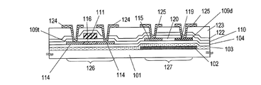
- FIG. 1 is a schematic cross-sectional view showing an example of the semiconductor device of the present embodiment.
- the semiconductor device of this embodiment typically includes a plurality of TFTs and a plurality of TFDs provided on the same substrate.
- a configuration of only a single TFT and a single TFD is illustrated. Yes.
- the semiconductor device of this embodiment includes a thin film transistor 126 and a thin film diode 127 formed on a substrate 101 via base films 103 and 104.
- the thin film transistor 126 includes a semiconductor layer 109t including a channel region 116, a source region and a drain region 114, a gate insulating film 110 provided over the semiconductor layer 109t, a gate electrode 111 that controls conductivity of the channel region 116,
- the electrode / wiring 124 is connected to the source region and the drain region 114, respectively.
- the thin film diode 127 includes a semiconductor layer 109d including at least an n-type region 115 and a p-type region 119, and electrodes / wirings 125 connected to the n-type region 115 and the p-type region 119, respectively.
- an intrinsic region 120 is provided between the n-type region 115 and the p-type region 119 in the semiconductor layer 109d.
- a silicon nitride film 122 and a silicon oxide film 123 are formed as an interlayer insulating film.
- a light shielding layer 102 is disposed between the semiconductor layer 109 d of the thin film diode 127 and the substrate 101.
- the semiconductor layer 109t of the thin film transistor 126 and the semiconductor layer 109d of the thin film diode 127 are crystalline semiconductor layers obtained by crystallizing the same amorphous semiconductor film.
- the semiconductor layer 109t of the thin film transistor 126 and the thin film diode It is crystallized by a method different from that of the semiconductor layer 109d of 127, and the concentration of the catalytic element is different.
- the semiconductor layer 109 d of the thin film diode 127 has a lower catalyst element concentration than the semiconductor layer 109 t of the thin film transistor 126.
- the n-channel thin film transistor 126 and the thin film diode 127 as shown in FIG. 1 are manufactured as follows.
- 2A to 2I are process cross-sectional views showing manufacturing steps of the thin film transistor 126 and the thin film diode 127 in the present embodiment, and the manufacturing steps sequentially proceed in the order of (A) ⁇ (I).
- a light shielding layer 102, base films 103 and 104, an amorphous semiconductor film 105 and a mask film 106 are formed on a substrate 101, and a catalytic element 107 is further added.
- a low alkali glass substrate or a quartz substrate can be used as the substrate 101.
- a low alkali glass substrate is used.
- heat treatment may be performed in advance at a temperature lower by about 10 to 20 ° C. than the glass strain point.
- a light shielding layer 102 is provided on the surface of the substrate 101 where the TFT and TFD are to be formed.
- the light shielding layer 102 functions to shield light from the substrate back surface direction with respect to the TFD.
- a metal film, a silicon film, or the like can be used as the light shielding layer 102.
- refractory metal tantalum (Ta), tungsten (W), molybdenum (Mo), or the like is preferable in consideration of heat treatment in a later manufacturing process.
- a Mo film was formed by sputtering and patterned to form the light shielding layer 102 shown in FIG.
- the thickness of the light shielding layer 102 is 30 to 200 nm, preferably 50 to 150 nm. In the present embodiment, the thickness is set to 100 nm, for example.
- base films 103 and 104 such as a silicon oxide film, a silicon nitride film, and a silicon oxynitride film are formed.
- a silicon oxynitride film produced from a material gas of SiH 4 , NH 3 , and N 2 O by a plasma CVD method is formed as a lower first base film 103, and similarly, A second base film 104 was formed by stacking SiH 4 and N 2 O as material gases by plasma CVD.
- the thickness of the silicon oxynitride film of the first base film 103 is 30 to 400 nm, for example 200 nm, and the thickness of the silicon oxide film of the second base film 104 is 50 to 200 nm, for example 100 nm.
- the two underlayer films 103 and 104 are used.
- a single layer of a silicon oxide film may be used.
- a silicon film (amorphous silicon film) 105 having an amorphous structure with a thickness of 20 to 150 nm (preferably 30 to 80 nm) is formed as an amorphous semiconductor film by plasma CVD, sputtering, or the like. It is formed by a known method. In this embodiment, an amorphous silicon film having a thickness of 50 nm is formed by plasma CVD.
- the base films 103 and 104 and the amorphous silicon film 105 can be formed by the same film formation method, they may be formed continuously. After the formation of the base films 103 and 104, it is possible to prevent contamination of the surface by not exposing the film to the air atmosphere, so that variations in characteristics of TFTs to be manufactured and fluctuations in threshold voltage can be reduced.
- a silicon oxide film or a silicon nitride film (thickness: 50 to 400 nm, for example, 200 nm) is formed, and a part of the pattern is opened by patterning to form a mask film 106 as shown in FIG. To do.
- the portion of the amorphous silicon film 105 where the TFT is formed is exposed through the opening of the mask film 106.
- an aqueous solution (nickel acetate aqueous solution) containing a catalytic element (nickel in this embodiment) 107 of about 1 to 10 ppm, for example, 5 ppm in terms of weight is applied by a spin coating method to form a catalytic element-containing layer.
- the catalytic element 107 selectively contacts the amorphous silicon film 105 at the opening of the mask film 106 to form a catalytic element addition region. This state corresponds to the state shown in FIG.
- the catalyst element 107 in addition to nickel (Ni), one kind selected from the group consisting of iron (Fe), cobalt (Co), tin (Sn), lead (Pb), palladium (Pd), and copper (Cu) Alternatively, it is preferable to use a plurality of kinds of elements. Although the catalytic effect is smaller than these elements, ruthenium (Ru), rhodium (Rh), osmium (Os), iridium (Ir), platinum (Pt), gold (Au), etc. also function as catalytic elements.
- Ru ruthenium
- Rh rhodium
- Os osmium
- Ir iridium
- Au gold
- the amount of the catalytic element to be doped is extremely small, and the concentration of the catalytic element on the surfaces of the amorphous silicon film 105 and the mask film 106 is managed by a total reflection X-ray fluorescence analysis (TRXRF) method. In this embodiment, it is about 5 ⁇ 10 12 atoms / cm 2 .
- TRXRF total reflection X-ray fluorescence analysis
- the surface of the amorphous silicon film 105 may be slightly oxidized with ozone water or the like in order to improve the wettability of the surface of the amorphous silicon film 105 during spin coating.
- a method of doping nickel by spin coating is used.
- a thin film made of a catalytic element in this embodiment, nickel film
- nickel film is deposited on the amorphous silicon film 105 by vapor deposition or sputtering. It is also possible to take the means to form
- a part of the amorphous silicon film 105 is crystallized.
- heat treatment is performed in an inert atmosphere, for example, in a nitrogen atmosphere.
- an annealing treatment at 500 to 650 ° C. for 30 minutes to 4 hours.
- heat treatment was performed at 600 ° C. for 1 hour.
- amorphous silicon film 105 While diffusing into the film 105, silicidation occurs, and the crystallization of the amorphous silicon film 105 proceeds using the silicidation as a nucleus. As a result, the amorphous silicon film 105 in that region is crystallized to become a crystalline silicon region (also referred to as “catalyst utilizing crystallization region”) 105a. At this time, the nickel 107 existing on the mask film 106 is blocked by the mask film 106 and does not reach the underlying amorphous silicon film, and the region below the mask film 106 remains in an amorphous state (non- Crystalline silicon region 105 '). Although crystallization is performed here by heat treatment using a furnace, crystallization may be performed by an RTA (Rapid Thermal Annealing) apparatus using a lamp or the like as a heat source.
- RTA Rapid Thermal Annealing
- a laser beam 108 is irradiated to the silicon film in which the crystalline silicon region 105a and the amorphous silicon region 105 'are mixed.
- the crystalline silicon region 105a into which the catalytic element has been introduced and selectively crystallized is reduced in crystal defects by the melting and solidifying process by irradiation with the laser beam 108, and a part thereof is recrystallized as a growth nucleus.
- a higher quality crystalline silicon region also referred to as a “high crystalline region”
- the amorphous region is crystallized in the process of melting and solidifying by irradiation with the laser beam 108 to form a crystalline silicon region (also referred to as a “low crystalline region”) 105c.
- an XeCl excimer laser (wavelength 308 nm) or a KrF excimer laser (wavelength 248 nm) can be applied.
- the beam size of the laser light at this time is shaped to be a long shape on the surface of the substrate 101, and the entire surface of the substrate is recrystallized by sequentially scanning in the direction perpendicular to the long direction. .
- laser irradiation is performed a plurality of times at an arbitrary point in the crystalline silicon region 105a and the amorphous region 105, and uniformity can be improved.
- the beam size is formed to be a long shape of 300 mm ⁇ 0.4 mm on the surface of the substrate 101, and scanning is performed sequentially with a step width of 0.02 mm in a direction perpendicular to the long direction. It was. That is, a total of 20 laser irradiations are performed at an arbitrary point on the silicon film.
- a laser that can be used at this time a YAG laser, a YVO4 laser, or the like can be used in addition to the above-described pulse oscillation type or continuous emission type KrF excimer laser and XeCl excimer laser.
- the irradiation energy density was 250 to 450 mJ / cm 2 , for example, 350 mJ / cm 2 . If the energy density of the laser beam at this time is too high, the crystalline state of the crystalline silicon region 105a obtained in the previous step will be reset.
- the crystal plane orientation of the crystalline silicon region 105b obtained in this way is almost determined in the solid phase crystallization process using the catalytic element, and is mainly composed of the ⁇ 111> crystal zone plane.
- Plane orientation and (211) plane orientation occupy 50% or more of the entire region.
- the average crystal grain size and the domain diameter of the crystal domain are 2 to 5 ⁇ m.
- the crystal plane orientation of the crystalline silicon region 105c crystallized from the amorphous state by laser irradiation is random, and (100) plane orientation and (111) plane orientation are particularly common. Both (100) plane orientation and (111) plane orientation do not fall within the group of ⁇ 111> crystal zone planes.
- the average crystal grain size is 100 to 300 nm.
- a gate insulating film 110 covering these island-like semiconductor layers 109t and 109d is formed.
- a silicon oxide film having a thickness of 20 to 150 nm is preferable.
- a silicon oxide film having a thickness of 100 nm is used.
- a conductive film is deposited on the gate insulating film 110 using a sputtering method, a CVD method, or the like, and this is patterned to form a gate electrode 111 of a later TFT.
- a conductive film is not formed over the island-shaped semiconductor layer 109d of the later TFD. It is desirable that the conductive film contains any of refractory metals W, Ta, Ti, Mo, or alloy materials thereof. Further, the thickness of the conductive film is desirably 300 to 600 nm. In this embodiment, for example, a tantalum (Ta) film having a thickness of 450 nm to which a small amount of nitrogen is added is used.
- a mask 112 made of a resist is formed over the gate insulating film 110 so as to cover part of the island-shaped semiconductor layer 109d to be an active region of the TFD later.
- an n-type impurity (phosphorus) 113 is ion-doped on the entire surface from above the substrate 101. The ion doping of the phosphorus 113 is performed so as to pass through the gate insulating film 110 and be implanted into the semiconductor layers 109t and 109d.
- the region exposed from the resist mask 112 and the island-shaped semiconductor layer 109t serving as the active region of the TFT are exposed from the gate electrode 111.
- Phosphorus 113 is implanted into the existing region.
- the region covered with the resist mask 112 and the gate electrode 111 is not doped with phosphorus 113.
- the region where the phosphorus 113 is implanted becomes the source region and the drain region 114 of the subsequent TFT, and the region where the phosphorus 113 is not implanted after being masked by the gate electrode 111 is the channel region of the TFT. 116.
- the region into which phosphorus 113 is implanted becomes the n + region 115 of the later TFD.
- a part of the island-shaped semiconductor layer 109d, which later becomes an active region of the TFD, and an active region of the TFT later A mask 117 made of a resist is formed on the gate insulating film 108 so as to cover the entire island-shaped semiconductor layer 109t.
- the entire surface of the substrate 101 is ion-doped with p-type impurities (boron) 118.
- boron p-type impurities
- boron 118 is implanted into a region exposed from the resist mask 117 in the island-like semiconductor layer 109d of TFD.
- the region covered by the mask 117 is not doped with boron 118.
- the region where boron 118 is implanted becomes the p + region 119 of the later TFD, and the region where phosphorus is not implanted in the previous step becomes the later intrinsic region 120. .
- the resist mask 118 is removed, and heat treatment is performed in an inert atmosphere, for example, in a nitrogen atmosphere.
- an inert atmosphere for example, in a nitrogen atmosphere.
- phosphorus doped in the source / drain region 114 of the TFT increases the solid solubility of nickel in the region, and the nickel existing in the channel region 116 is transferred from the channel region to the source / drain region. Move to the drain region in the direction indicated by arrow 121.
- the nickel concentration in these regions is higher than that of the channel region 116 and is 1 ⁇ 10 18 / cm 3 or more.
- a general heating furnace may be used, but it is more preferable to use RTA (Rapid Thermal Annealing).
- RTA Rapid Thermal Annealing
- a system in which high temperature inert gas is sprayed on the substrate surface and the temperature is raised and lowered instantaneously is suitable.
- a silicon oxide film or a silicon nitride film is formed as an interlayer insulating film.
- a two-layer structure of a silicon nitride film 122 and a silicon oxide film 123 is used.
- contact holes are formed, and TFT electrodes / wirings 124 and TFD electrodes / wirings 125 are formed of a metal material.
- annealing is performed at 350 to 450 ° C. in a nitrogen atmosphere or a hydrogen mixed atmosphere at 1 atm to complete the thin film transistor 126 and the thin film diode 127 shown in FIG.
- a protective film made of a silicon nitride film or the like may be provided on the thin film transistor 126 and the thin film diode 127 for the purpose of protecting them.
- the respective semiconductor layers of the TFT and TFD, and further the channel region of the TFT and the intrinsic region of the TFD can be formed separately.
- optimum element characteristics required for each of the TFT and the TFD can be simultaneously realized by using a semiconductor layer formed by crystallizing the same amorphous semiconductor film.
- the nickel concentration of the TFD semiconductor layer is substantially zero and is not observed by any measurement means.
- catalyst elements gather in the source / drain regions 114 and become 1 ⁇ 10 18 / cm 3 or more as described above, and the channel region 116 is 1 ⁇ 10 15 to 1 ⁇ 10 16. / Cm 3 or so.
- 3A to 3F are process cross-sectional views for explaining a method of manufacturing the semiconductor layer 210t of the thin film transistor and the semiconductor layer 210d of the thin film diode in this embodiment, in the order of (A) ⁇ (F). Accordingly, the manufacturing process proceeds sequentially.
- a light shielding layer 202 made of Mo or the like is provided on a substrate (a glass substrate in this embodiment) 201, and further, for example, nitriding is performed in order to prevent impurity diffusion from the substrate.
- a silicon film was stacked as a lower first base film 203, and a silicon oxide film was stacked thereon as a second base film 204.
- an amorphous silicon film 205 having a thickness of 30 to 80 nm, for example, 50 nm is formed.
- the base insulating film and the amorphous semiconductor film may be formed continuously without being released to the atmosphere.
- a mask film 206 made of a silicon oxide film is formed to a thickness of about 200 nm. As shown in FIG. 3A, the mask insulating film has an opening for adding a catalytic element to the semiconductor film.
- an aqueous solution (nickel acetate aqueous solution) containing about 30 ppm of catalyst element (nickel in this embodiment) 207 in terms of weight is applied by a spin coating method to form a catalyst element-containing layer.
- the catalytic element 207 in the catalytic element-containing layer selectively contacts the amorphous silicon film 205 at the opening of the mask film 206 to form a catalytic element addition region. This state corresponds to FIG.
- a method of doping nickel 207 by spin coating is used.
- a thin film made of a catalytic element in this embodiment, nickel film
- a thin film made of a catalytic element is deposited on an amorphous silicon film by vapor deposition or sputtering. It is also possible to take the means to form
- heat treatment is performed at 500 to 650 ° C. (preferably 550 to 620 ° C.) for 1 to 10 hours. In this embodiment, heat treatment is performed at 600 ° C. for 2 hours.
- first catalyst utilizing crystal first crystallized to form a crystalline silicon region (“first catalyst utilizing crystal”). 205a).
- crystallization proceeds in a direction substantially parallel to the substrate 201 (direction indicated by an arrow 208) starting from the crystalline silicon region 205a which is a crystallization region, and is macroscopic.
- a crystalline silicon region (also referred to as a “second catalyst utilizing crystallization region”) 205b having a uniform crystal growth direction is formed.
- the nickel existing on the mask film 206 is blocked by the mask film 206 and does not reach the lower amorphous silicon film, and the crystal of the amorphous silicon film 205 is only formed by the nickel introduced in the opening region. Is done.
- the region where the lateral crystal growth does not reach remains as an amorphous silicon region 205c.
- the mask film (silicon oxide film) 206 is removed to obtain the state shown in FIG.
- a laser beam 209 is irradiated on the silicon film in which the crystalline silicon regions 205a and 205b and the amorphous silicon region 205c are mixed.
- an XeCl excimer laser (wavelength: 308 nm) is used, and scanning is performed so that parts of the beams overlap each other. was applied to improve uniformity.
- the crystalline silicon regions 205a and 205b selectively crystallized using the catalyst element are reduced in crystal defects by the melting and solidifying process by irradiation with the laser beam 209, and recrystallized using a part of them as a growth nucleus.
- higher-quality crystalline silicon regions 205d and 205e are obtained.
- the crystalline silicon region (also referred to as “second high crystalline region”) 205e crystallized in the lateral direction has a higher quality than the crystalline silicon region (also referred to as “first high crystalline region”) 205d, This is a crystalline silicon film having higher crystallinity.
- the amorphous silicon region 205c is crystallized in the process of melting and solidifying by irradiation with the laser beam 209 to form a crystalline silicon region (also referred to as a “low crystalline region”) 205f.
- the laser irradiation energy density at this time was 250 to 450 mJ / cm 2 , for example, 350 mJ / cm 2 .
- the energy density of the laser beam is too high, the crystalline state of the crystalline silicon region 205b obtained in the previous step is reset.
- the crystal plane orientation of the crystalline silicon region 205e thus obtained is almost determined in the solid phase crystallization process using the catalytic element, and is mainly composed of the ⁇ 111> crystal zone plane.
- Plane orientation and (211) plane orientation occupy 50% or more of the entire region.
- the crystal state is composed of crystal domains (substantially the same plane orientation region) along one direction, and is not a concept like a crystal grain.
- the crystal plane orientation of the crystalline silicon region 204d is mainly composed of a ⁇ 111> crystal zone plane, and the (110) plane orientation and the (211) orientation are dominant. And a crystal domain (1 ⁇ m to 3 ⁇ m) smaller than the crystalline silicon region 205e is formed.
- the crystal plane orientation of the crystalline silicon region 205f crystallized from an amorphous state by laser irradiation is random, and (100) plane orientation and (111) plane orientation are particularly common. Both (100) plane orientation and (111) plane orientation do not fall within the group of ⁇ 111> crystal zone planes.
- the average crystal grain size is 100 to 300 nm.
- an island-shaped semiconductor layer 210t which later becomes an active region (source / drain region, channel region) of a TFT, using a high-quality crystalline silicon region 205e crystallized in the lateral direction.
- an island-shaped semiconductor layer 210d which later becomes an active region (n + / p + region, intrinsic region) of the TFD, is formed using the crystalline silicon region 205f.
- the TFT and TFD are completed by using the island-like semiconductor layers 210t and 210d as active regions of the TFT and TFD by the same method as in the first embodiment.
- a higher-quality crystalline silicon film crystal-grown in the lateral direction can be used as the semiconductor layer of the TFT, and a TFT having a higher current driving capability can be realized.
- the optimum states required for the respective semiconductor layers of the TFT and TFD, as well as the channel region of the TFT and the intrinsic region of the TFD can be created separately.
- optimum element characteristics required for each of the TFT and the TFD can be simultaneously realized by using a semiconductor layer formed by crystallizing the same amorphous semiconductor film.
- FIG. 1 A method of manufacturing the semiconductor device according to the third embodiment of the present invention will be described.
- a display pixel TFT and its auxiliary capacitor (capacitor), a driving CMOS configuration TFT circuit, and a photosensor TFD are simultaneously manufactured on a glass substrate.
- the semiconductor device of this embodiment can be used for an active matrix liquid crystal display device with a built-in optical sensor, an organic EL display device, or the like.
- FIG. 6 is a cross-sectional process diagram, and the manufacturing process sequentially proceeds in the order of FIG. 4 (A) ⁇ FIG. 6 (K).
- a film or the like is formed and patterned to form the light shielding layer 302.
- a molybdenum (Mo) film is formed as a metal film by sputtering.
- the thickness of the Mo film is preferably 30 to 300 nm, more preferably 50 to 200 nm, for example 100 nm.
- a base film such as a silicon oxide film, a silicon nitride film, or a silicon oxynitride film is formed on the glass substrate 301 and the light shielding layer 302 by, for example, a plasma CVD method. These base films are provided to prevent diffusion of impurities from the glass substrate.
- a silicon nitride film having a thickness of about 100 nm is formed as a lower first base film 303, and a silicon oxide film having a thickness of about 200 nm is stacked on the second base film 304.
- an intrinsic (I-type) amorphous silicon film (a-Si film) 305 having a thickness of about 20 to 80 nm, for example, 40 nm is formed by a plasma CVD method or the like. Further, a silicon oxide film or a silicon nitride film (thickness: 50 to 400 nm, for example, 150 nm) is formed, and a mask film 306 partially opened is obtained by patterning. The amorphous silicon film 305 is exposed in the opening of the mask film 306.
- a catalytic element is added to the surface of the amorphous silicon film 305.
- An aqueous solution nickel acetate aqueous solution
- catalyst element in this embodiment, nickel
- the catalytic element 307 is selectively brought into contact with the amorphous silicon film 305 at the opening of the mask film 306 to form a catalytic element addition region. This state corresponds to the state shown in FIG.
- Fe iron
- Co cobalt
- Sn tin
- Pb lead
- Pd palladium
- Cu copper
- seed elements ruthenium (Ru), rhodium (Rh), osmium (Os), iridium (Ir), platinum (Pt), gold (Au), etc. also function as catalytic elements.
- the amount of the catalytic element to be doped is extremely small, and the concentration of the catalytic element on the surface of the amorphous silicon film 305 is managed by the total reflection X-ray fluorescence (TRXRF) method. In this embodiment, it is about 5 ⁇ 10 12 atoms / cm 2 .
- TRXRF total reflection X-ray fluorescence
- the surface of the amorphous silicon film 305 may be slightly oxidized with ozone water or the like in order to improve the wettability of the surface of the amorphous silicon film 305 during spin coating.
- a method of doping nickel by a spin coating method is used.
- a thin film made of a catalytic element in this embodiment, a nickel film
- a nickel film is deposited on the amorphous silicon film 305 by vapor deposition or sputtering. It is also possible to take the means to form
- heat treatment is performed in an inert atmosphere, for example, in a nitrogen atmosphere to cause crystallization.
- the heat treatment is preferably performed at 550 to 620 ° C. for 1 to 4 hours. In this embodiment, as an example, heat treatment was performed at 600 ° C. for 2 hours.
- crystallization is performed here by heat treatment using a furnace, crystallization may be performed by an RTA (Rapid Thermal Annealing) apparatus using a lamp or the like as a heat source.
- RTA Rapid Thermal Annealing
- the laser beam 309 is irradiated over the entire substrate 301 as shown in FIG.
- the crystalline silicon region 305a that is directly crystallized by adding the catalytic element
- the crystalline silicon region 305b that is grown in the lateral direction
- the amorphous silicon region 305c that is not subjected to lateral crystal growth
- the laser beam 309 is irradiated.
- the crystalline silicon regions 305a and 305b that are selectively crystallized by introducing the catalytic element crystal defects are reduced by the melting and solidifying process by irradiation with the laser beam 309, and a part thereof is recrystallized as a growth nucleus.
- higher-quality crystalline silicon regions 305x and 305y are obtained.
- the crystalline silicon region 305y crystal-grown in the lateral direction is a crystalline silicon film with higher quality and higher crystallinity.
- the amorphous silicon region 305c is crystallized in the process of melting and solidifying by irradiation with the laser beam 309, so that a crystalline silicon region 305z is formed.
- an XeCl excimer laser (wavelength 308 nm) or a KrF excimer laser (wavelength 248 nm) can be applied.
- the beam size of the laser beam at this time is shaped to be a long shape on the surface of the substrate 301, and the entire surface of the substrate is recrystallized by sequentially scanning in the direction perpendicular to the long direction. . At this time, scanning is performed so that parts of the beams overlap each other, so that laser irradiation is performed a plurality of times at any one of the crystalline silicon regions 305a and 305b and the amorphous region 305c, thereby improving uniformity. I can plan.
- the beam size is formed to be a long shape of 300 mm ⁇ 0.4 mm on the surface of the substrate 301, and scanning is performed sequentially with a step width of 0.02 mm in the direction perpendicular to the long direction. It was. That is, a total of 20 laser irradiations are performed at an arbitrary point on the silicon film.
- a laser that can be used at this time a YAG laser, a YVO4 laser, or the like can be used in addition to the above-described pulse oscillation type or continuous emission type KrF excimer laser and XeCl excimer laser.
- an active region (source / source) of an n-channel TFT which will later constitute a driver circuit portion, using a crystalline silicon region 305y that has been crystallized laterally using a catalytic element.
- An island-shaped semiconductor layer 310n serving as a drain region and a channel region) and an island-shaped semiconductor layer 310p serving as an active region (source / drain region and channel region) of the p-channel TFT are formed.
- an island-shaped semiconductor layer 310d that later becomes an active region (n + / p + region, intrinsic region) of the photosensor TFD is formed.
- the active region (source / drain region, channel region) of the n-channel TFT for driving the pixel electrode and the island-shaped semiconductor layer 310g constituting the lower electrode of the auxiliary capacitor connected thereto the active region of the TFT will be described later.
- Is formed by the crystalline silicon region 305y, and the region to be the lower electrode of the auxiliary capacitor is formed by the crystalline silicon region 305z. That is, in the semiconductor layer 310g, two different types of crystalline regions 305y and 305z partially exist.
- p-type is imparted to all of these semiconductor layers or a part of the semiconductor layers at a concentration of about 1 ⁇ 10 16 to 5 ⁇ 10 17 / cm 3 for the purpose of controlling the threshold voltage.
- Boron (B) may be doped as an impurity element. Boron (B) may be added by an ion doping method, or may be doped at the same time when an amorphous silicon film is formed.
- a gate insulating film 311 is formed and an n-type impurity (phosphorus) 313 is implanted.
- TEOS Tetra Ethoxy Ortho Silicate
- RF plasma CVD at a substrate temperature of 150 to 600 ° C., preferably 300 to 450 ° C. together with oxygen.
- the substrate temperature may be set to 350 to 600 ° C., preferably 400 to 550 ° C. by TEOS as a raw material together with ozone gas by a low pressure CVD method or an atmospheric pressure CVD method.
- annealing is performed at 500 to 600 ° C. for 1 to 4 hours in an inert gas atmosphere in order to improve the bulk characteristics of the gate insulating film itself and the interface characteristics of the crystalline silicon film / gate insulating film. May be.
- an insulating film containing other silicon may be used as a single layer or a stacked structure.
- resist masks 312n, 312p, 312g and 312d made of photoresist are provided on the respective island-like semiconductor layers 310n, 310p, 310g and 310d.
- a resist mask 312n is provided in the central portion to be a channel region later, and both ends are exposed.
- a resist mask 312g is provided in a portion that will later become the active region of the image TFT, and a portion that later becomes the lower electrode of the auxiliary capacitor. Exposed.
- the semiconductor layer 310p that later becomes an active region of a p-channel TFT and the semiconductor layer 310d that becomes an active region of a TFD the entire semiconductor layer is covered with resist masks 312p and 312d.
- a low concentration impurity (phosphorus) 313 is implanted into the island-shaped semiconductor layers 310n and 310g by ion doping using the resist masks 312n, 312p, 312g, and 312d as masks.
- the doping gas phosphine (PH 3 ) is used, the acceleration voltage is set to 60 to 90 kV, for example, 70 kV, and the dose amount is set to 5 ⁇ 10 12 to 5 ⁇ 10 14 cm ⁇ 2 , for example, 5 ⁇ 10 13 cm ⁇ 2 .
- low-concentration phosphorus 313 is implanted into regions that are not covered with the resist masks 312n and 312g, and become low-concentration n-type impurity regions 314n and 314g, respectively.
- the phosphorus 313 is not implanted into the regions masked by the resist masks 312n and 312g.
- the entire semiconductor layer is masked by the resist masks 312p and 312d, respectively, and phosphorus 313 is not implanted at all.
- a refractory metal is deposited by sputtering to form a conductive film, which is patterned to form gate electrodes 315n, 315p, and 315g, and an upper electrode 315s of the auxiliary capacitor.
- the gate electrode 315g of the later pixel TFT is divided into two for the purpose of reducing the leakage current when the pixel TFT is turned off, and a so-called dual gate structure in which two TFTs are connected in series. To do.
- the gate structure of the pixel TFT may be a triple gate structure or a quad gate structure in which the number of gate electrodes 315g (the number of TFTs connected in series) is further increased.
- an element selected from the group consisting of tantalum (Ta) or tungsten (W), molybdenum (Mo), and titanium (Ti), an alloy containing the element as a main component, or an alloy combining the elements (Typically, a Mo—W alloy or a Mo—Ta alloy) may be used.
- tungsten silicide, titanium silicide, or molybdenum silicide may be used as an alternative material.
- a tungsten (W) film (thickness: 300 to 600 nm, for example, 450 nm) is formed as the conductive film.
- the concentration of impurities contained in the conductive film may be reduced. For example, by setting the oxygen concentration to 30 ppm or less, a specific resistance value of 20 ⁇ cm or less can be realized.
- a doping mask 316 made of a photoresist is provided so as to cover the semiconductor layer 310d of the later photosensor TFD so as to be slightly covered, and the gate electrodes 315n, 315p, and 315g and the upper electrode 315s of the auxiliary capacitor are masked by ion doping.
- a second low-concentration impurity (phosphorus) 317 is implanted into the active region of each TFT.
- the second low-concentration phosphorus 317 is implanted into the regions that are not covered with the gate electrodes 315n, 315p, and 315g and the auxiliary capacitor upper electrode 315s.
- the impurity 317 is not implanted into the regions masked by the gate electrodes 315n, 315p, and 315g, the auxiliary capacitor upper electrode 315s, and the resist mask 316. This state corresponds to FIG.
- a photoresist doping mask 319g is then provided so as to cover the gate electrode 315g of the subsequent pixel TFT to a large extent.
- a photoresist mask 319p is provided so as to cover the gate electrode 315p further and expose the outer edge of the semiconductor layer 310p.
- a doping mask 319d made of a photoresist is provided so as to expose a part of the semiconductor layer 310d.
- a high concentration of impurity (phosphorus) 320 is added to each semiconductor layer by ion doping using the gate electrode 315n of the later n-channel TFT, the upper electrode 315s of the auxiliary capacitor, and the resist masks 319p, 319g, and 319d as masks.
- the doping gas phosphine (PH 3 ) is used, the acceleration voltage is set to 60 to 90 kV, for example, 70 kV, and the dose amount is set to 1 ⁇ 10 15 to 1 ⁇ 10 16 cm ⁇ 2 , for example, 5 ⁇ 10 15 cm ⁇ 2 .
- an impurity (phosphorus) 320 is implanted at a high concentration in the region exposed from the gate electrode 315n, and the source / drain region 321n of the later n-channel TFT is formed.
- the gate electrode 315n is formed in a self-aligned manner.
- the region where the low-concentration phosphorus is implanted in the previous step is the LDD that overlaps the gate electrode 315n.
- GOLD Gate Overlapped Lightly Doped Drain
- an impurity (phosphorus) 320 is implanted at a high concentration in a region exposed from the resist mask 319g, and a source / drain region 321g of the subsequent pixel TFT (n-channel type) is formed. Then, of the region covered with the resist mask 319g and not doped with the high concentration phosphorus 320, the region where the low concentration phosphorus is implanted in the previous step becomes the LDD region 323g, and the low concentration phosphorus is also implanted. The region under the non-gate electrode 315g becomes a channel region 328g. In the pixel TFT, the LDD structure offset to the outside of the gate electrode in this way can greatly reduce the leakage current during the TFT off operation.
- an impurity (phosphorus) 320 is implanted at a high concentration into a region exposed from the resist mask 319p, thereby forming a high-concentration n-type region 321p.
- the region 323p covered with the resist mask 319p and implanted with the low concentration phosphorus 317 remains as it is.
- an impurity (phosphorus) 320 is implanted at a high concentration into a region exposed from the resist mask 319d, so that a high concentration n-type region 321d is formed.
- the n-type impurity element (phosphorus) 320 concentration in the regions 321n, 321p, 321g, and 321d at this time is 1 ⁇ 10 19 to 1 ⁇ 10 21 / cm 3 .
- the n-type impurity element (phosphorus) 313 has a concentration in the film of 5 ⁇ 10 17 to 1 ⁇ 10 19 / cm 3 in the GOLD region 322n of the n-channel TFT, and n in the LDD region 323g of the pixel TFT.
- the concentration of the type impurity element (phosphorus) 317 in the film is 1 ⁇ 10 17 to 5 ⁇ 10 18 / cm 3, and effectively functions as a GOLD region or an LDD region in such a range. .
- a semiconductor layer 310n of an n-channel TFT a semiconductor layer 310g that constitutes a pixel TFT, and its auxiliary capacitor are newly added.
- doping masks 324n, 324g, and 324d are provided.
- an impurity imparting p-type to the p-channel TFT semiconductor layer 310p and the TFD semiconductor layer 310d by ion doping using the resist masks 324n, 324g, and 324d and the gate electrode 315p of the p-channel TFT as a mask.
- (Boron) 325 is injected.
- Diborane (B 2 H 6 ) is used as a doping gas, the acceleration voltage is 40 kV to 90 kV, for example 75 kV, and the dose is 1 ⁇ 10 15 to 1 ⁇ 10 16 cm ⁇ 2 , for example 3 ⁇ 10 15 cm ⁇ 2 .
- boron 325 is implanted at a high concentration in the semiconductor layer 310p of the p-channel TFT other than the lower portion of the gate electrode 315p.
- the region 323p becomes p-type by inverting the n-type impurity phosphorus 317 implanted at a low concentration in the previous process, and becomes the source / drain of the subsequent TFT in a self-aligned manner with respect to the gate electrode 315p.
- Region 326p is formed.
- a high concentration boron 325 is implanted and functions as the gettering region 327p.
- the region under the gate electrode 315p is not implanted with high-concentration boron, and becomes a channel region 328p.
- boron 325 is implanted at a high concentration in a region exposed from the resist mask 324d, and a p-type region 326d of the later TFD is formed.
- the concentration of the p-type impurity element (boron) 325 in the regions 326p, 326d, and 327p is 1.5 ⁇ 10 19 to 3 ⁇ 10 21 / cm 3 .
- the n-channel TFT semiconductor layer 310n and the pixel TFT and the semiconductor layer 310g serving as the lower electrode of the auxiliary capacitor are covered with the masks 324n and 324g, so that the boron 325 is not doped.
- heat treatment is performed in an inert atmosphere, for example, in a nitrogen atmosphere.
- the RTA process is used in which the substrate is moved to a high temperature atmosphere one by one and a high temperature nitrogen gas is blown to raise and lower the temperature rapidly.
- the temperature was increased / decreased at a temperature increase / decrease rate exceeding 200 ° C./min.
- the heat treatment at this time other methods can be used, and the conditions may be set by the practitioner for convenience. Of course, a general diffusion furnace (furnace furnace) or a lamp heating type RTA may be used.
- phosphorus and boron doped in a high concentration in the gettering region 327p formed outside the source / drain region, and lattice defects generated at the time of boron doping Etc. move nickel present in the channel region 328p and the source / drain region 326p from the channel region to the source / drain region and the gettering region in the same direction as indicated by the arrow 329.
- nickel moves to the source / drain regions 321n and 321g of the n-channel TFT and the pixel TFT and the gettering region 327p of the p-channel TFT and TFD, so that the nickel concentration in these regions Is 1 ⁇ 10 18 / cm 3 or more.
- the source / drain regions 321n and 321g of the n-channel TFT and the pixel TFT, the GOLD region 322n, the LDD region 323g, the auxiliary capacitance lower electrode region 322g, and the n-type region 321d of the TFD are doped.
- the activation of the p-type impurity (phosphorus) and the p-type impurity (boron) doped in the source / drain region 326p of the p-channel TFT and the p-type region 326d of the TFD are simultaneously performed.
- the sheet resistance value of the n-channel TFT, the source / drain region of the pixel TFT, and the n-type region of the TFD is about 0.5 to 1 k ⁇ / ⁇
- the sheet resistance value of the GOLD region and the auxiliary capacitor lower electrode region. was about 20 to 60 k ⁇ / ⁇
- the sheet resistance value in the LDD region was 40 to 100 k ⁇ / ⁇ .
- the sheet resistance values of the source / drain region of the p-channel TFT and the p-type region of the TFD were about 0.7 to 1.2 k ⁇ / ⁇ .
- the gettering region In the gettering region, the doped n-type impurity element phosphorus and the p-type impurity element boron cancel the carriers (electrons and holes), and the sheet resistance value is several tens of k ⁇ / ⁇ , as source / drain regions.
- the gettering region is arranged so as not to hinder the movement of carriers and does not cause a problem in operation.
- an interlayer insulating film 331 is formed.
- a silicon nitride film, a silicon oxide film, or a silicon nitride oxide film is formed to a thickness of 400 to 1500 nm (typically 600 to 1000 nm).
- a silicon nitride film 330 having a thickness of 200 nm and a silicon oxide film 331 having a thickness of 700 nm are stacked to form a two-layer structure.
- a film forming method a plasma CVD method was used, and a silicon nitride film was continuously formed using SiH 4 and NH 3 as raw material gases, and a silicon oxide film was formed using TEOS and O 2 as raw materials.
- the interlayer insulating film is not limited to this, and another insulating film containing silicon may have a single layer or a laminated structure, and an organic insulating film such as acrylic may be provided on the upper layer.
- a heat treatment is performed at a temperature of 300 to 500 ° C. for about 30 minutes to 4 hours to perform a step of hydrogenating the semiconductor layer.
- hydrogen atoms are supplied to the active region / gate insulating film interface to terminate and inactivate dangling bonds that degrade TFT characteristics.
- heat treatment was performed at 400 ° C. for 1 hour in a nitrogen atmosphere containing about 3% hydrogen. If the amount of hydrogen contained in the interlayer insulating film (particularly the silicon nitride film 330) is sufficient, the effect can be obtained even if heat treatment is performed in a nitrogen atmosphere.
- plasma hydrogenation using hydrogen excited by plasma may be performed.
- TFT electrodes and wirings 332n, 332p, 332g, and 332d are formed of a metal material, for example, a two-layer film of titanium nitride and aluminum.
- the titanium nitride film is provided as a barrier film for the purpose of preventing aluminum from diffusing into the semiconductor layer.
- annealing is performed at 350 ° C. for one hour, and the driver n-channel thin film transistor 333, the p-channel thin film transistor 334, the pixel switching thin film transistor 335, and the auxiliary capacitor 336 connected thereto are shown in FIG. And the thin film diode 337 for optical sensors is completed.
- a transparent conductive film such as ITO is connected to one side of the electrode / wiring 332g to form a pixel electrode. Further, if necessary, contact holes are also provided on the gate electrodes 315n and 315p, and necessary electrodes are connected by the wiring 332.
- a protective film made of a silicon nitride film or the like may be provided on each TFT.
- each TFT manufactured in accordance with embodiments as high as 120 ⁇ 150cm 2 / Vs at 250 ⁇ 300cm 2 / Vs, p-channel type TFT with n-channel TFT, and the threshold voltage N-type TFT It shows very good characteristics of about 1V and about -1.5V for P-type TFT.
- a circuit such as an inverter chain or a ring oscillator is formed with a CMOS structure circuit in which the n-channel TFT and the p-channel TFT manufactured in this embodiment are complementarily formed, the reliability is higher than the conventional one. And stable circuit characteristics.
- the dark current value of the TFD was reduced to 1/5 or less compared to the case where the TFT was formed on the same substrate as the TFT using the conventional method, and the light / dark ratio as the photosensor element was improved by 5 times or more. In this way, by creating a semiconductor layer for each element, the characteristics for each device can be optimized.
- FIGS. 7A to 7E are cross-sectional process diagrams for explaining a manufacturing method of the TFT and TFD in this embodiment, and the processes sequentially proceed in the order of FIGS. 7A to 7E.
- a light shielding layer 402 is formed on the surface of the glass substrate 401 on which TFTs and TFDs are to be formed to shield light from the substrate back surface direction in the later TFD.
- a silicon nitride film is formed as a lower first base film 403 on the glass substrate 401 and the light shielding layer 402 by the same method as in the third embodiment.
- a silicon oxide film was stacked over the second base film 404.
- an intrinsic (I-type) amorphous silicon film 405 having a thickness of about 50 nm is formed by a plasma CVD method or the like.
- a silicon oxide film or a silicon nitride film is formed, and a mask film 406 having an opening is formed by patterning. In the opening of the mask film 406, the amorphous silicon film 405 is exposed.
- a catalyst element 407 is added to the surfaces of the amorphous silicon film 405 and the mask film 406 by a method similar to that of the third embodiment.
- a catalyst element-containing layer is formed using nickel as the catalyst element 407.
- the catalytic element 407 is selectively brought into contact with the amorphous silicon film 405 at the opening of the mask film 406 to form a catalytic element addition region. This state corresponds to the state shown in FIG.
- heat treatment is performed in an inert atmosphere, for example, in a nitrogen atmosphere, and the amorphous silicon film 405 is crystallized.
- the amorphous silicon film 405 is crystallized using nickel added to the surface of the amorphous silicon film 405 as a catalyst to form a crystalline silicon film 405a.
- Nickel present on the mask film 406 is blocked by the mask film 406 and does not reach the underlying amorphous silicon film, and remains as an amorphous silicon region 405c.
- the amorphous silicon film 405 is crystallized only by the nickel introduced in the opening region.
- a laser beam 409 is irradiated over the entire substrate by the same method as in the third embodiment. That is, the laser beam 409 is uniformly irradiated to the region 405a crystallized by adding the catalyst element and the region 405c remaining in an amorphous state by the mask film.
- the crystalline silicon region 405a into which the catalytic element has been introduced and selectively crystallized is reduced in crystal defects by the melting and solidifying process by irradiation with the laser beam 409, and a part thereof is recrystallized as a growth nucleus.
- a higher quality crystalline silicon region 405x is obtained.
- the amorphous silicon region 405c is crystallized in the melting and solidifying process by irradiation with the laser beam 409, and a crystalline silicon region 405z is formed.
- the crystalline silicon region 405z obtained by crystallizing the amorphous region with a laser beam is used to form an island-shaped semiconductor layer 410d that later becomes an active region (n + / p + region, intrinsic region) of the photosensor TFD.
- the active region of the TFT will be described later.
- the region to be formed is formed by the crystalline silicon region 405x, and the region to be the lower electrode of the auxiliary capacitor is formed by the crystalline silicon region 405z. That is, in the semiconductor layer 410g, two different crystalline regions are partially present.
- the island-shaped semiconductor layer 410g is used as the active region of the n-channel TFT and the island-shaped semiconductor layer 410p is used as the active region of the p-channel TFT.
- the region 405x crystallized using the catalytic element is used as an active region of the pixel TFT, and the region 405y crystallized by laser irradiation is used as the lower electrode of the auxiliary capacitor in the semiconductor layer 410g.
- TFD active region each TFT and TFD is completed.
- a driving CMOS configuration TFT circuit and a semiconductor layer serving as an active region of a display pixel TFT and a lower electrode of the auxiliary capacitor are formed on a glass substrate by a method different from the third and fourth embodiments.
- An n-channel TFT semiconductor layer, a p-channel TFT semiconductor layer, and a photosensor TFD semiconductor layer are formed at the same time.
- FIGS. 8A to 8E are process cross-sectional views for explaining a manufacturing method of the TFT and TFD in the present embodiment, and the processes sequentially proceed in the order of FIGS. 8A to 8E.
- a light shielding layer 502 is formed on the surface of the glass substrate 501 on which TFTs and TFDs are to be formed to shield light from the substrate rear surface direction in the subsequent TFD.
- a silicon nitride film is formed as a lower first base film 503 on the glass substrate 501 and the light shielding layer 502 by the same method as in the third embodiment.
- a second base film 504 was formed by laminating a silicon oxide film thereon.
- an intrinsic (I-type) amorphous silicon film 505 having a thickness of about 50 nm is formed by a plasma CVD method or the like.
- a silicon oxide film or a silicon nitride film is formed, and a mask film 506 is formed by patterning to open a part. In the opening of the mask film 506, the amorphous silicon film 505 is exposed.
- the catalytic element 507 is added to the surfaces of the amorphous silicon film 505 and the mask film 506 in the same manner as in the third embodiment.
- Nickel is used as the catalyst element 507 to form a catalyst element-containing layer.
- the catalytic element 507 is selectively brought into contact with the amorphous silicon film 505 at the opening of the mask film 506 to form a catalytic element addition region. This state corresponds to the state shown in FIG.
- heat treatment is performed in an inert atmosphere, for example, in a nitrogen atmosphere, and the amorphous silicon film 505 is crystallized.
- the amorphous silicon film 505 is crystallized by using nickel added to the surface of the amorphous silicon film as a catalyst to form a crystalline silicon film 505a.
- the crystalline structure in which the crystallization progresses in a direction substantially parallel to the substrate (direction indicated by an arrow 508) starting from the crystalline silicon region 505a, which is the previously crystallized region, and the macroscopic crystal growth direction is aligned.
- a silicon region 505b is formed.
- the nickel existing on the mask film 506 is blocked by the mask film 506 and does not reach the underlying amorphous silicon film, and the crystal of the amorphous silicon film 505 is only formed by nickel introduced in the opening region. Is done. The region where the lateral crystal growth does not reach remains as an amorphous silicon region 505c.
- laser light 509 is irradiated over the entire substrate by the same method as in the third embodiment. That is, the region 505a crystallized by adding the catalyst element directly, the crystalline silicon region 505b crystallized laterally using the catalyst element as a seed, and the region 505c remaining in an amorphous state by the mask film are uniform. Is irradiated with a laser beam 509.
- the crystalline silicon regions 505a and 505b that are selectively crystallized by introducing the catalytic element are reduced in crystal defects by the melting and solidifying process by irradiation with the laser beam 509, and recrystallized by using a part of them as a growth nucleus.
- higher quality crystalline silicon regions 505x and 505y are obtained.
- the amorphous silicon region 505c is crystallized in the melting and solidifying process by irradiation with the laser beam 509, and a crystalline silicon region 505z is formed.
- an island-shaped semiconductor layer 510d that later becomes an active region (n + / p + region, intrinsic region) of the photosensor TFD;
- the entire island-shaped semiconductor layer 510g constituting the active region (source / drain region, channel region) of the n-channel TFT for driving the pixel electrode and the lower electrode of the auxiliary capacitor connected thereto is formed.
- the island-shaped semiconductor layer 510n is used as the active region of the n-channel TFT
- the island-shaped semiconductor layer 510p is used as the active region of the p-channel TFT
- the island-shaped semiconductor layer 510g is used as the pixel TFT.
- the TFT and TFD are completed using the island-like semiconductor layer 510d as the active region of the TFD as the active region and the lower electrode of the auxiliary capacitor.
- the active region of the pixel TFT uses a semiconductor layer that is crystallized by directly irradiating the amorphous silicon film with laser light without using a catalytic element.
- a CMOS-structured TFT that constitutes the driver circuit can achieve high driving capability with high field-effect mobility, and a pixel TFT can reduce leakage current during off-operation.
- TFD the dark current is lowered, and a high contrast ratio is obtained as an optical sensor.
- the semiconductor layer formed by crystallizing the same amorphous semiconductor film the optimum element characteristics required for each TFT and TFD can be simultaneously realized.
- this embodiment is preferably applied to an organic EL display device.
- a bottom emission type organic EL display device can be manufactured by forming a transparent electrode layer, a light emitting layer, and an upper electrode layer in this order on a substrate provided with a thin film transistor and a thin film diode by the above method. it can.
- a top emission type organic EL display device may be manufactured by forming a transparent electrode as the upper electrode layer. In that case, the substrate need not be translucent.
- the semiconductor device of this embodiment is a display device having a sensor function. These display devices are configured using a substrate on which TFTs and TFDs are formed using any of the embodiments described above.
- the display device having the sensor function is, for example, a liquid crystal display device with a touch sensor, and includes a display region and a frame region located around the display region.
- the display area has a plurality of display units (pixels) and a plurality of photosensor units.
- Each display unit includes a pixel electrode and a pixel switching TFT, and each photosensor unit includes a TFD.
- a display drive circuit for driving each display unit is provided in the frame region, and a drive circuit TFT is used as the drive circuit.
- the pixel switching TFT, the driving circuit TFT, and the TFD of the optical sensor unit are formed on the same substrate by the method described in the first to fifth embodiments.
- at least the pixel switching TFT among TFTs used in the display device may be formed on the same substrate as the TFD of the photosensor portion by the above method. Alternatively, it may be separately provided on another substrate.
- the optical sensor unit is disposed adjacent to a corresponding display unit (for example, primary color pixels).
- a corresponding display unit for example, primary color pixels.
- One photosensor unit may be arranged for one display unit, or a plurality of photosensor units may be arranged. Or you may arrange
- one optical sensor unit can be provided for a color display pixel composed of three primary color (RGB) pixels.
- RGB primary color
- the sensitivity of the TFD constituting the optical sensor unit may be reduced. Therefore, no color filter is provided on the observer side of the optical sensor unit. It is preferable.
- a display device to which an ambient sensor that controls the display brightness in accordance with the illuminance of external light can be configured by arranging a TFD for an optical sensor in the frame region.
- the optical sensor unit can also function as a color image sensor.
- FIG. 9 is a circuit diagram showing an example of the configuration of the optical sensor unit arranged in the display area.
- the optical sensor unit includes an optical sensor thin film diode 601, a signal storage capacitor 602, and a thin film transistor 603 for extracting a signal stored in the capacitor 602. After the RST signal is input and the RST potential is written into the node 604, when the potential of the node 604 is decreased due to light leakage, the gate potential of the thin film transistor 603 is changed to open and close the TFT gate. Thereby, the signal VDD can be taken out.
- FIG. 10 is a schematic cross-sectional view showing an example of an active matrix type touch panel liquid crystal display device.
- one photosensor unit is arranged for each pixel.
- the liquid crystal display device shown in the figure includes a liquid crystal module 702 and a backlight 701 disposed on the back side of the liquid crystal module 702.
- the liquid crystal module 702 includes, for example, a light-transmitting back substrate, a front substrate disposed so as to face the back substrate, and a liquid crystal layer provided between these substrates. Composed.
- the liquid crystal module 702 includes a plurality of display portions (primary color pixels), and each display portion includes a pixel electrode (not shown) and a pixel switching thin film transistor 705 connected to the pixel electrode. Yes.
- An optical sensor unit including a thin film diode 706 is disposed adjacent to each display unit.
- a color filter is disposed on the viewer side of each display unit, but no color filter is provided on the viewer side of the optical sensor unit.
- a light shielding layer 707 is disposed between the thin film diode 706 and the backlight 701, and light from the backlight 701 is shielded by the light shielding layer 707 and does not enter the thin film diode 706, but only the external light 704 is thin film diode 706. Is incident on. The incident of the external light 704 is sensed by the thin film diode 706 to realize a light sensing touch panel.
- the light shielding layer 707 may be arranged so that at least light from the backlight 701 does not enter the intrinsic region of the thin film diode 706.
- FIG. 11 is a schematic plan view showing an example of a rear substrate in an active matrix type touch panel liquid crystal display device.
- the liquid crystal display device of the present embodiment is composed of a large number of pixels (R, G, B pixels), but only two pixels are shown here for the sake of simplicity.
- Each of the rear substrates 1000 is disposed adjacent to each of the plurality of display portions (pixels) each including the pixel electrode 22 and the pixel switching thin film transistor 24, and includes a photosensor photodiode 26 and a signal storage capacitor 28. And an optical sensor unit including an optical sensor follower thin film transistor 29.
- the thin film transistor 24 has, for example, the same configuration as the TFT described in the third embodiment, that is, a dual gate LDD structure having two gate electrodes and an LDD region.
- the source region of the thin film transistor 24 is connected to the pixel source bus line 34, and the drain region is connected to the pixel electrode 22.
- the thin film transistor 24 is turned on / off by a signal from the pixel gate bus line 32.
- display is performed by applying a voltage to the liquid crystal layer by the pixel electrode 22 and the counter electrode formed on the front substrate disposed to face the back substrate 1000 and changing the alignment state of the liquid crystal layer.
- the photosensor photodiode 26 has the same configuration as the TFD described in the third embodiment, for example, and is located between the p + type region 26p, the n + type region 26n, and the regions 26p and 26n. And an intrinsic region 26i.
- the signal storage capacitor 28 has a gate electrode layer and a Si layer as electrodes, and a capacitance is formed by a gate insulating film.
- the p + -type region 26p in the photosensor photodiode 26 is connected to the RST signal line 36 for photosensors, and the n + -type region 26n is connected to the lower electrode (Si layer) in the signal storage capacitor 28. 28 is connected to the optical sensor RWS signal line 38.
- n + -type region 26 n is connected to the gate electrode layer in the photosensor follower thin film transistor 29.
- the source and drain regions of the photosensor follower thin film transistor 29 are connected to the photosensor VDD signal line 40 and the photosensor COL signal line 42, respectively.
- the photosensor photodiode 26, the signal storage capacitor 28, and the photosensor follower thin film transistor 29 correspond to the thin film diode 701, the capacitor 702, and the thin film transistor 703 of the drive circuit shown in FIG. It constitutes the drive circuit for the optical sensor. The operation at the time of optical sensing by this drive circuit will be described below.
- the RWS signal is written into the signal storage capacitor 28 by the RWS signal line 38.
- a positive electric field is generated on the n + -type region 26 n side of the photosensor photodiode 26, and the photosensor photodiode 26 is in a reverse bias state.
- the photosensor photodiode 26 present in the region of the substrate surface where light is irradiated light leaks and the charge is released to the RST signal line 36 side.
- the potential on the n + -type region 26n side is lowered, and the gate voltage applied to the photosensor follower thin film transistor 29 is changed by the potential change.
- VDD signal is applied from the VDD signal line 40 to the source side of the photosensor follower thin film transistor 29.
- the gate voltage fluctuates as described above, the value of the current flowing to the COL signal line 42 connected to the drain side changes, so that the electrical signal can be extracted from the COL signal line 42.
- the RST signal is written from the COL signal line 42 to the photosensor photodiode 26, and the potential of the signal storage capacitor 28 is reset. Optical sensing is possible by repeating the operations (1) to (5) while scanning.
- the configuration of the back substrate in the touch panel liquid crystal display device of the present embodiment is not limited to the configuration shown in FIG.
- an auxiliary capacitor (Cs) may be provided in each pixel switching TFT.
- a photosensor unit is provided adjacent to each of the RGB pixels.
- one photosensor is provided for three pixel sets (color display pixels) composed of RGB pixels. The part may be arranged.
- the thin film diode 706 is arranged in the display area and used as a touch sensor.
- the thin film diode 706 is formed outside the display area and back It can also be used as an ambient sensor for controlling the luminance of the light 701 in accordance with the illuminance of the external light 704.
- FIG. 12 is a perspective view illustrating a liquid crystal display device with an ambient light sensor.
- the liquid crystal display device 2000 includes an LCD substrate 50 having a display area 52, a gate driver 56, a source driver 58 and an optical sensor unit 54, and a backlight 60 disposed on the back side of the LCD substrate 50.
- An area of the LCD substrate 50 that is located around the display area 52 and in which the drivers 56 and 58 and the optical sensor unit 54 are provided may be referred to as a “frame area”.
- the brightness of the backlight 60 is controlled by a backlight control circuit (not shown).
- TFTs are used for the display area 52 and the drivers 56 and 58, and TFDs are used for the optical sensor unit 54.
- the optical sensor unit 54 generates an illuminance signal based on the illuminance of external light, and inputs the illuminance signal to the backlight control circuit using a connection using a flexible substrate.
- the backlight control circuit generates a backlight control signal based on the illuminance signal and outputs it to the backlight 60.
- an organic EL display device with an ambient light sensor can be configured.
- Such an organic EL display device can have a configuration in which a display unit and a photosensor unit are arranged on the same substrate, like the liquid crystal display device shown in FIG. There is no need to provide the light 60.
- the optical sensor unit 54 is connected to the source driver 58 by wiring provided on the substrate 50, and an illuminance signal from the optical sensor unit 54 is input to the source driver 58.
- the source driver 58 changes the luminance of the display area 52 based on the illuminance signal.
- a circuit for performing analog driving and a circuit for performing digital driving can be simultaneously formed on a glass substrate.
- a circuit that performs analog driving includes a source side driving circuit, a pixel portion, and a gate side driving circuit.
- the source side driving circuit includes a shift register, a buffer, a sampling circuit (transfer gate), and a gate side driving.
- the circuit is provided with a shift register, a level shifter, and a buffer. Further, if necessary, a level shifter circuit may be provided between the sampling circuit and the shift register.
- a memory and a microprocessor can be formed.
- a semiconductor device including a TFT and a TFD having both the optimal semiconductor film for each semiconductor element and having good characteristics can be obtained.
- the TFT used for the driving circuit and the TFT for switching the pixel electrode have a high field effect mobility and an ON / OFF ratio, a low dark current value when used as an optical sensor, and an SN for light.
- a TFD having a high ratio (a current value ratio between light and dark) can be manufactured in the same manufacturing process using semiconductor layers formed by crystallizing the same amorphous semiconductor film as active regions.
- each semiconductor element can be optimized. Optimal device characteristics can be obtained. Furthermore, the high-performance semiconductor element can be realized by a simple manufacturing method, and the product can be made compact, high-performance, and low in cost.
- the applicable range of the present invention is extremely wide, and it can be applied to a semiconductor device provided with a TFT and a TFD, or an electronic device in any field having such a semiconductor device.
- a CMOS circuit or a pixel portion formed by implementing the present invention can be used for an active matrix liquid crystal display device or an organic EL display device.
- Such a display device can be used for a display screen of a mobile phone or a portable game machine, a monitor of a digital camera, or the like. Therefore, the present invention can be applied to all electronic devices in which a liquid crystal display device or an organic EL display device is incorporated.
- the present invention can be suitably used particularly for an active matrix type liquid crystal display device, an organic EL display device, an image sensor, an optical sensor, and an electronic device combining them.
- the present invention may be applied to an image sensor including an optical sensor using TFD and a driving circuit using TFT.
Landscapes
- Recrystallisation Techniques (AREA)
- Thin Film Transistor (AREA)
- Solid State Image Pick-Up Elements (AREA)
- Metal-Oxide And Bipolar Metal-Oxide Semiconductor Integrated Circuits (AREA)
Abstract
Description

本発明による第1の実施形態の半導体装置を説明する。本実施形態の半導体装置は、同一の基板上に形成されたnチャネル型TFTとTFDとを備えており、例えばセンサー部を備えたアクティブマトリクス型の表示装置として用いられる。
本発明による第2の実施形態の半導体装置の製造方法を説明する。ここでは、前述の第1実施形態とは異なる方法で、TFTの半導体層とTFDの半導体層とをガラス基板上に作り分ける。
本発明による第3の実施形態の半導体装置の製造方法を説明する。ここでは、ガラス基板上に表示用の画素TFTおよびその補助容量(コンデンサー)と、駆動用のCMOS構成TFT回路、および、フォトセンサーTFDを同時に作製する。本実施形態の半導体装置は、光センサー内蔵型のアクティブマトリクス型の液晶表示装置や有機EL表示装置等に利用することができる。
本発明による第4の実施形態の半導体装置の製造方法を説明する。ここでは、第3実施形態とは異なる方法で、ガラス基板上に表示用の画素TFTの活性領域およびその補助容量の下部電極となる半導体層と、駆動用のCMOS構成TFT回路を構成するnチャネル型TFTの半導体層およびpチャネル型TFTの半導体層と、そしてフォトセンサーTFDの半導体層とを同時作製する。
本発明による第5の実施形態の半導体装置の製造方法を説明する。ここでは、第3および第4実施形態とは異なる方法で、ガラス基板上に表示用の画素TFTの活性領域およびその補助容量の下部電極となる半導体層と、駆動用のCMOS構成TFT回路を構成するnチャネル型TFTの半導体層およびpチャネル型TFTの半導体層と、フォトセンサーTFDの半導体層とを同時に作製する。
本発明による第6の実施形態の半導体装置を説明する。本実施形態の半導体装置は、センサー機能を備えた表示装置である。これらの表示装置は、上述してきた何れかの実施形態を用いて、TFTおよびTFDが形成された基板を用いて構成されている。
102、202 遮光層
103、203、104、204 下地膜
105、205 非晶質半導体膜
106、206 マスク膜
107、207 触媒元素
105a、205a、205b 結晶質ケイ素領域(触媒利用結晶化領域)
105b、205d、205e 結晶質ケイ素領域(高結晶質領域)
105c、205f 結晶質ケイ素領域(低結晶質領域)
109t、210t 薄膜トランジスタの半導体層
109d、210d 薄膜ダイオードの半導体層
110 ゲート絶縁膜
111 ゲート電極
114 ソース・ドレイン領域
115 n型領域
116 チャネル領域
119 p型領域
124 電極・配線
120 真性領域
123 層間絶縁膜
125 電極・配線
126 薄膜トランジスタ
127 薄膜ダイオード
Claims (25)
- チャネル領域、ソース領域およびドレイン領域を含む半導体層と、前記チャネル領域の導電性を制御するゲート電極と、前記半導体層と前記ゲート電極との間に設けられたゲート絶縁膜とを有する薄膜トランジスタ、および、少なくともn型領域とp型領域とを含む半導体層を有する薄膜ダイオードを備えた半導体装置であって、
前記薄膜トランジスタの半導体層および前記薄膜ダイオードの半導体層は、同一の非晶質半導体膜を結晶化することによって形成された結晶質半導体層であり、
前記薄膜トランジスタの半導体層は、前記非晶質半導体膜の結晶化を促進する働きを持つ触媒元素を含み、
前記薄膜ダイオードの半導体層は、前記触媒元素を実質的に含まない半導体装置。 - 前記薄膜ダイオードの半導体層は、結晶の(100)面、あるいは/および(111)面となる面方位で主に構成されている請求項1に記載の半導体装置。
- 前記薄膜ダイオードは、前記薄膜ダイオードの半導体層のうち前記n型領域と前記p型領域との間に位置する真性領域を含み、前記真性領域は、結晶の(100)面、あるいは/および(111)面となる面方位で主に構成されている請求項1に記載の半導体装置。
- 前記薄膜トランジスタの半導体層のうち少なくとも前記チャネル領域は、結晶の〈111〉晶帯面が配向した面方位で主に構成されている請求項1から3のいずれかに記載の半導体装置。
- 前記薄膜トランジスタの半導体層のうち少なくとも前記チャネル領域は、結晶の(110)面、あるいは/および(211)面となる面方位で主に構成されている請求項4に記載の半導体装置。
- 前記薄膜トランジスタの半導体層のうち少なくとも前記チャネル領域は、柱状結晶の集まりで構成され、各々の柱状結晶の成長方向は、薄膜トランジスタにおけるキャリアの移動方向に概ね平行である請求項1から5のいずれかに記載の半導体装置。
- 前記薄膜トランジスタの半導体層では、前記触媒元素は析出しておらず固溶した状態で含まれる請求項1から6のいずれかに記載の半導体装置。
- 前記薄膜トランジスタの半導体層の前記ソース領域あるいは前記ドレイン領域における前記触媒元素の濃度は、前記チャネル領域における前記触媒元素の濃度よりも高い請求項1から7のいずれかに記載の半導体装置。
- 前記薄膜トランジスタは、前記薄膜トランジスタの半導体層のうち前記チャネル領域、ソース領域およびドレイン領域以外の領域に形成されたゲッタリング領域を有し、前記ゲッタリング領域における前記触媒元素の濃度は、前記チャネル領域、前記ソース領域およびドレイン領域における前記触媒元素の濃度よりも高い請求項1から7のいずれかに記載の半導体装置。
- 前記薄膜トランジスタは、nチャネル型薄膜トランジスタおよびpチャネル型薄膜トランジスタを含む複数の薄膜トランジスタである請求項1から9のいずれかに記載の半導体装置。
- 前記触媒元素はニッケルである請求項1から10のいずれかに記載の半導体装置。
- (a)表面に非晶質半導体膜が形成された基板を用意する工程と、
(b)前記非晶質半導体膜の一部にだけ、結晶化を促進する触媒元素を選択的に添加する工程と、
(c)前記触媒元素を選択的に添加した非晶質半導体膜に対して加熱処理を行って、前記非晶質半導体膜の一部を結晶化させて触媒利用結晶化領域を形成し、他の部分を非晶質領域のまま残す工程と、
(d)前記触媒利用結晶化領域および前記非晶質領域にレーザー光を照射して、前記触媒利用結晶化領域をさらに結晶化させる、あるいは再結晶化させることによって形成された高結晶質領域と、前記非晶質領域を結晶化させることによって形成された低結晶質領域とを含む結晶質半導体膜を得る工程と
(e)前記結晶質半導体膜をパターニングして、後に薄膜トランジスタの活性領域となる第1の島状半導体層および後に薄膜ダイオードの活性領域となる第2の島状半導体層を形成する工程であって、前記第1の島状半導体層は前記高結晶質領域を含み、前記第2の島状半導体層は前記低結晶質領域を含む工程と
を包含する半導体装置の製造方法。 - 前記工程(c)では、前記非晶質半導体膜のうち前記触媒元素が添加された部分を結晶化させて前記触媒利用結晶化領域を形成する請求項12に記載の半導体装置の製造方法。
- 前記工程(c)は、
(c1)前記非晶質半導体膜のうち前記触媒元素が添加された部分を結晶化させて第1触媒利用結晶化領域を形成する工程と、
(c2)前記第1触媒利用結晶化領域からその周辺部へ横方向に結晶成長させて第2触媒利用結晶化領域を形成する工程と
を含み、
前記工程(d)は、前記第1触媒利用結晶化領域をさらに結晶化、あるいは再結晶化させて第1高結晶質領域を形成するとともに、前記第2触媒利用結晶化領域を結晶化、あるいは再結晶化させて第2高結晶質領域を形成する工程を含み、
前記工程(e)において、前記第1の島状半導体層は前記第2高結晶質領域を含む請求項12に記載の半導体装置の製造方法。 - 前記工程(e)は、前記結晶質半導体膜の前記高結晶質領域を用いて、前記第1の島状半導体層のうち後に薄膜トランジスタのチャネル領域となる領域を形成する工程を含む請求項12から14のいずれかに記載の半導体装置の製造方法。
- 前記工程(e)は、前記結晶質半導体膜の前記低結晶質領域を用いて、前記第2の島状半導体層のうち後に薄膜ダイオードの真性領域となる領域を形成する工程を含む請求項12から15のいずれかに記載の半導体装置の製造方法。
- 前記工程(e)は、前記結晶質半導体膜の前記高結晶質領域を用いて、前記第1の島状半導体層全体を形成する工程である請求項12から16のいずれかに記載の半導体装置の製造方法。
- 前記工程(e)は、前記結晶質半導体膜の前記低結晶質領域を用いて、前記第2の島状半導体層全体を形成する工程である請求項12から17のいずれかに記載の半導体装置の製造方法。
- 前記工程(e)は、前記結晶質半導体膜の前記第1高結晶質領域を用いて、前記第1の島状半導体層のうち後に薄膜トランジスタのソース領域あるいは/およびドレイン領域となる領域の少なくとも一部を形成し、前記第2高結晶質領域を用いて、前記第1の島状半導体層のうち後に薄膜トランジスタのチャネル領域となる領域を形成する工程である請求項14に記載の半導体装置の製造方法。
- 前記工程(e)は、前記結晶質半導体膜の前記低結晶質領域を用いて、後にコンデンサーの片方の電極となる半導体層を形成する工程をさらに含む請求項12から19のいずれかに記載の半導体装置の製造方法。
- 前記工程(e)は、前記結晶質半導体膜の前記低結晶質領域を用いて、後に他の薄膜トランジスタの活性領域となる島状半導体層を形成する工程をさらに含む請求項12から20のいずれかに記載の半導体装置の製造方法。
- 前記工程(b)は、
前記非晶質半導体膜上に、開口部を有するマスクを形成する工程と、
前記開口部を通して、前記非晶質半導体膜の選択された領域に前記触媒元素を添加する工程と
を含む請求項12から21のいずれかに記載の半導体装置の製造方法。 - 前記工程(d)は、レーザー光を照射する前の前記触媒利用結晶化領域の結晶状態を完全にリセットせず、かつ、前記非晶質領域を結晶化させ得る照射エネルギー密度でレーザー光を照射する工程を含む請求項12から22のいずれかに記載の半導体装置の製造方法。
- 前記基板は透光性を有し、
前記工程(a)の前に、
前記基板のうち後に薄膜ダイオードの活性領域となる第2の島状半導体層が形成される領域の下部となる部分に、前記基板の裏面からの光を遮光するための遮光層を形成する工程をさらに包含する請求項12から23のいずれかに記載の半導体装置の製造方法。 - (f)少なくとも、前記第1の島状半導体層の上にゲート絶縁膜を形成する工程と、
(g)前記第1の島状半導体層の上の前記ゲート絶縁膜上にゲート電極を形成する工程と、
(h)前記第1の島状半導体層のうち後のソース領域及びドレイン領域となる領域に、不純物元素をドーピングする工程と、
(i)前記第2の島状半導体層のうち後のn型領域となる領域に、n型不純物元素をドーピングする工程と、
(j)前記第2の島状半導体層のうち後のp型領域となる領域に、p型不純物元素をドーピングする工程と、
を包含する請求項12から23のいずれかに記載の半導体装置の製造方法。
Priority Applications (4)
| Application Number | Priority Date | Filing Date | Title |
|---|---|---|---|
| EP09754424A EP2290693A4 (en) | 2008-05-29 | 2009-05-26 | SEMICONDUCTOR COMPONENT AND MANUFACTURING METHOD THEREFOR |
| US12/995,056 US20110073918A1 (en) | 2008-05-29 | 2009-05-26 | Semiconductor device and manufacturing method thereof |
| JP2010514359A JP5096572B2 (ja) | 2008-05-29 | 2009-05-26 | 半導体装置およびその製造方法 |
| CN200980119066.XA CN102047426B (zh) | 2008-05-29 | 2009-05-26 | 半导体装置及其制造方法 |
Applications Claiming Priority (2)
| Application Number | Priority Date | Filing Date | Title |
|---|---|---|---|
| JP2008-141536 | 2008-05-29 | ||
| JP2008141536 | 2008-05-29 |
Publications (1)
| Publication Number | Publication Date |
|---|---|
| WO2009144915A1 true WO2009144915A1 (ja) | 2009-12-03 |
Family
ID=41376805
Family Applications (1)
| Application Number | Title | Priority Date | Filing Date |
|---|---|---|---|
| PCT/JP2009/002308 Ceased WO2009144915A1 (ja) | 2008-05-29 | 2009-05-26 | 半導体装置およびその製造方法 |
Country Status (5)
| Country | Link |
|---|---|
| US (1) | US20110073918A1 (ja) |
| EP (1) | EP2290693A4 (ja) |
| JP (1) | JP5096572B2 (ja) |
| CN (1) | CN102047426B (ja) |
| WO (1) | WO2009144915A1 (ja) |
Cited By (3)
| Publication number | Priority date | Publication date | Assignee | Title |
|---|---|---|---|---|
| WO2011129441A1 (ja) * | 2010-04-16 | 2011-10-20 | シャープ株式会社 | 半導体装置 |
| JP2011222954A (ja) * | 2010-04-14 | 2011-11-04 | Samsung Mobile Display Co Ltd | 多結晶シリコン層とその製造方法、該多結晶シリコン層を利用した薄膜トランジスタ及び該薄膜トランジスタを備えた有機発光表示装置 |
| WO2012060320A1 (ja) * | 2010-11-04 | 2012-05-10 | シャープ株式会社 | 半導体装置およびその製造方法 |
Families Citing this family (12)
| Publication number | Priority date | Publication date | Assignee | Title |
|---|---|---|---|---|
| KR20120129592A (ko) | 2011-05-20 | 2012-11-28 | 삼성디스플레이 주식회사 | 평판 표시 장치용 백플레인, 이를 포함하는 평판 표시 장치, 및 그 제조 방법 |
| JP2013125826A (ja) | 2011-12-14 | 2013-06-24 | Renesas Electronics Corp | 半導体装置及び半導体装置の製造方法 |
| CN104867964B (zh) * | 2015-05-18 | 2019-02-22 | 京东方科技集团股份有限公司 | 阵列基板、其制造方法以及有机发光二极管显示装置 |
| CN105552134A (zh) * | 2016-01-20 | 2016-05-04 | 中国科学院物理研究所 | 场效应二极管 |
| CN105679769A (zh) * | 2016-01-27 | 2016-06-15 | 深圳市华星光电技术有限公司 | 一种tft基板、显示装置以及制造方法 |
| CN110312962A (zh) * | 2017-02-20 | 2019-10-08 | 夏普株式会社 | 有源矩阵基板和液晶显示装置 |
| CN108288621B (zh) * | 2018-03-09 | 2021-01-26 | 京东方科技集团股份有限公司 | 阵列基板的制造方法、阵列基板及显示面板 |
| CN111830743B (zh) * | 2020-07-10 | 2023-03-31 | Tcl华星光电技术有限公司 | 一种阵列基板及其制备方法 |
| CN112542386B (zh) * | 2020-11-03 | 2022-07-08 | 北海惠科光电技术有限公司 | 显示面板和薄膜晶体管的制造方法及其制造设备 |
| CN113113354B (zh) * | 2021-03-18 | 2022-04-08 | 武汉华星光电技术有限公司 | 光学器件及其制备方法、显示面板 |
| CN114203735A (zh) * | 2021-12-06 | 2022-03-18 | 深圳市华星光电半导体显示技术有限公司 | 驱动基板及其制作方法、显示面板 |
| US20230282644A1 (en) * | 2022-03-03 | 2023-09-07 | Taiwan Semiconductor Manufacturing Company, Ltd. | Layout design for rf circuit |
Citations (4)
| Publication number | Priority date | Publication date | Assignee | Title |
|---|---|---|---|---|
| JPH06275807A (ja) | 1993-03-22 | 1994-09-30 | Semiconductor Energy Lab Co Ltd | 半導体回路およびその作製方法 |
| JPH06275808A (ja) | 1993-03-22 | 1994-09-30 | Semiconductor Energy Lab Co Ltd | 半導体回路およびその作製方法 |
| JPH06275806A (ja) * | 1993-03-22 | 1994-09-30 | Semiconductor Energy Lab Co Ltd | 半導体回路およびその作製方法 |
| JPH06275805A (ja) * | 1993-03-22 | 1994-09-30 | Semiconductor Energy Lab Co Ltd | 半導体回路およびその作製方法 |
Family Cites Families (11)
| Publication number | Priority date | Publication date | Assignee | Title |
|---|---|---|---|---|
| US5501989A (en) * | 1993-03-22 | 1996-03-26 | Semiconductor Energy Laboratory Co., Ltd. | Method of making semiconductor device/circuit having at least partially crystallized semiconductor layer |
| US5488000A (en) * | 1993-06-22 | 1996-01-30 | Semiconductor Energy Laboratory Co., Ltd. | Method of fabricating a thin film transistor using a nickel silicide layer to promote crystallization of the amorphous silicon layer |
| JP3853393B2 (ja) * | 1995-03-03 | 2006-12-06 | タイコエレクトロニクスアンプ株式会社 | カード用コネクタ組立体 |
| JP3675886B2 (ja) * | 1995-03-17 | 2005-07-27 | 株式会社半導体エネルギー研究所 | 薄膜半導体デバイスの作製方法 |
| US6197624B1 (en) * | 1997-08-29 | 2001-03-06 | Semiconductor Energy Laboratory Co., Ltd. | Method of adjusting the threshold voltage in an SOI CMOS |
| US6218219B1 (en) * | 1997-09-29 | 2001-04-17 | Semiconductor Energy Laboratory Co., Ltd. | Semiconductor device and fabrication method thereof |
| TW504846B (en) * | 2000-06-28 | 2002-10-01 | Semiconductor Energy Lab | Semiconductor device and manufacturing method thereof |
| JP4413569B2 (ja) * | 2003-09-25 | 2010-02-10 | 株式会社 日立ディスプレイズ | 表示パネルの製造方法及び表示パネル |
| JP2005235870A (ja) * | 2004-02-17 | 2005-09-02 | Sharp Corp | 結晶性半導体膜の作製方法、結晶性半導体膜、半導体装置の製造方法、半導体装置、結晶性薄膜ダイオードの製造方法、結晶性薄膜ダイオード、結晶性薄膜トランジスタの製造方法、結晶性薄膜トランジスタおよびディスプレイ装置 |
| WO2008132862A1 (ja) * | 2007-04-25 | 2008-11-06 | Sharp Kabushiki Kaisha | 半導体装置およびその製造方法 |
| JP2009010125A (ja) * | 2007-06-27 | 2009-01-15 | Sharp Corp | 半導体装置およびその製造方法 |
-
2009
- 2009-05-26 EP EP09754424A patent/EP2290693A4/en not_active Withdrawn
- 2009-05-26 CN CN200980119066.XA patent/CN102047426B/zh not_active Expired - Fee Related
- 2009-05-26 WO PCT/JP2009/002308 patent/WO2009144915A1/ja not_active Ceased
- 2009-05-26 US US12/995,056 patent/US20110073918A1/en not_active Abandoned
- 2009-05-26 JP JP2010514359A patent/JP5096572B2/ja not_active Expired - Fee Related
Patent Citations (4)
| Publication number | Priority date | Publication date | Assignee | Title |
|---|---|---|---|---|
| JPH06275807A (ja) | 1993-03-22 | 1994-09-30 | Semiconductor Energy Lab Co Ltd | 半導体回路およびその作製方法 |
| JPH06275808A (ja) | 1993-03-22 | 1994-09-30 | Semiconductor Energy Lab Co Ltd | 半導体回路およびその作製方法 |
| JPH06275806A (ja) * | 1993-03-22 | 1994-09-30 | Semiconductor Energy Lab Co Ltd | 半導体回路およびその作製方法 |
| JPH06275805A (ja) * | 1993-03-22 | 1994-09-30 | Semiconductor Energy Lab Co Ltd | 半導体回路およびその作製方法 |
Non-Patent Citations (1)
| Title |
|---|
| See also references of EP2290693A4 |
Cited By (6)
| Publication number | Priority date | Publication date | Assignee | Title |
|---|---|---|---|---|
| JP2011222954A (ja) * | 2010-04-14 | 2011-11-04 | Samsung Mobile Display Co Ltd | 多結晶シリコン層とその製造方法、該多結晶シリコン層を利用した薄膜トランジスタ及び該薄膜トランジスタを備えた有機発光表示装置 |
| WO2011129441A1 (ja) * | 2010-04-16 | 2011-10-20 | シャープ株式会社 | 半導体装置 |
| CN102859693A (zh) * | 2010-04-16 | 2013-01-02 | 夏普株式会社 | 半导体装置 |
| US8803151B2 (en) | 2010-04-16 | 2014-08-12 | Sharp Kabushiki Kaisha | Semiconductor device |
| CN102859693B (zh) * | 2010-04-16 | 2015-12-16 | 夏普株式会社 | 半导体装置 |
| WO2012060320A1 (ja) * | 2010-11-04 | 2012-05-10 | シャープ株式会社 | 半導体装置およびその製造方法 |
Also Published As
| Publication number | Publication date |
|---|---|
| JPWO2009144915A1 (ja) | 2011-10-06 |
| JP5096572B2 (ja) | 2012-12-12 |
| EP2290693A4 (en) | 2013-02-27 |
| CN102047426B (zh) | 2013-02-06 |
| US20110073918A1 (en) | 2011-03-31 |
| EP2290693A1 (en) | 2011-03-02 |
| CN102047426A (zh) | 2011-05-04 |
Similar Documents
| Publication | Publication Date | Title |
|---|---|---|
| JP5096572B2 (ja) | 半導体装置およびその製造方法 | |
| CN101663758B (zh) | 半导体装置及其制造方法 | |
| JP5314040B2 (ja) | 半導体装置の製造方法 | |
| JP3904512B2 (ja) | 半導体装置およびその製造方法、並びに半導体装置を備えた電子機器 | |
| KR100515279B1 (ko) | 반도체 장치 및 그 제조방법 | |
| WO2010058532A1 (ja) | 半導体装置およびその製造方法、ならびに半導体装置を用いた表示装置 | |
| JP4115283B2 (ja) | 半導体装置およびその製造方法 | |
| US8829526B2 (en) | Semiconductor device, method for manufacturing same, and display device | |
| JP2008166785A (ja) | 薄膜トランジスタとその製造方法及び有機電界発光表示装置 | |
| JP2008300630A (ja) | 半導体装置およびその製造方法 | |
| JP2009010125A (ja) | 半導体装置およびその製造方法 | |
| JP2004165185A (ja) | 半導体膜およびその製造方法ならびに半導体装置およびその製造方法 | |
| US20120009710A1 (en) | Method of forming ldd of tft, method of fabricating tft and organic light emitting device using the method | |
| US20110175535A1 (en) | Semiconductor device, method for manufacturing same and display device | |
| JP4115153B2 (ja) | 半導体装置の製造方法 | |
| JP4437404B2 (ja) | 半導体装置とその製造方法 | |
| JP2010177362A (ja) | 半導体装置およびその製造方法ならびに表示装置 | |
| JP4115441B2 (ja) | 半導体装置およびその製造方法 | |
| JP4514862B2 (ja) | 半導体装置の作製方法 | |
| JP4954365B2 (ja) | 半導体装置の作製方法 | |
| WO2011158780A1 (ja) | 半導体装置およびその製造方法 | |
| JP4115406B2 (ja) | 半導体装置およびその製造方法 | |
| JP2009016600A (ja) | 半導体装置およびその製造方法 |
Legal Events
| Date | Code | Title | Description |
|---|---|---|---|
| WWE | Wipo information: entry into national phase |
Ref document number: 200980119066.X Country of ref document: CN |
|
| 121 | Ep: the epo has been informed by wipo that ep was designated in this application |
Ref document number: 09754424 Country of ref document: EP Kind code of ref document: A1 |
|
| WWE | Wipo information: entry into national phase |
Ref document number: 2010514359 Country of ref document: JP |
|
| WWE | Wipo information: entry into national phase |
Ref document number: 2009754424 Country of ref document: EP |
|
| WWE | Wipo information: entry into national phase |
Ref document number: 12995056 Country of ref document: US |
|
| NENP | Non-entry into the national phase |
Ref country code: DE |