WO2009148151A1 - 摺動補助機構 - Google Patents
摺動補助機構 Download PDFInfo
- Publication number
- WO2009148151A1 WO2009148151A1 PCT/JP2009/060337 JP2009060337W WO2009148151A1 WO 2009148151 A1 WO2009148151 A1 WO 2009148151A1 JP 2009060337 W JP2009060337 W JP 2009060337W WO 2009148151 A1 WO2009148151 A1 WO 2009148151A1
- Authority
- WO
- WIPO (PCT)
- Prior art keywords
- latch
- case
- assist mechanism
- operating member
- slider
- Prior art date
- Legal status (The legal status is an assumption and is not a legal conclusion. Google has not performed a legal analysis and makes no representation as to the accuracy of the status listed.)
- Ceased
Links
Images










Classifications
-
- E—FIXED CONSTRUCTIONS
- E05—LOCKS; KEYS; WINDOW OR DOOR FITTINGS; SAFES
- E05F—DEVICES FOR MOVING WINGS INTO OPEN OR CLOSED POSITION; CHECKS FOR WINGS; WING FITTINGS NOT OTHERWISE PROVIDED FOR, CONCERNED WITH THE FUNCTIONING OF THE WING
- E05F1/00—Closers or openers for wings, not otherwise provided for in this subclass
- E05F1/08—Closers or openers for wings, not otherwise provided for in this subclass spring-actuated, e.g. for horizontally sliding wings
- E05F1/16—Closers or openers for wings, not otherwise provided for in this subclass spring-actuated, e.g. for horizontally sliding wings for sliding wings
-
- E—FIXED CONSTRUCTIONS
- E05—LOCKS; KEYS; WINDOW OR DOOR FITTINGS; SAFES
- E05F—DEVICES FOR MOVING WINGS INTO OPEN OR CLOSED POSITION; CHECKS FOR WINGS; WING FITTINGS NOT OTHERWISE PROVIDED FOR, CONCERNED WITH THE FUNCTIONING OF THE WING
- E05F5/00—Braking devices, e.g. checks; Stops; Buffers
- E05F5/003—Braking devices, e.g. checks; Stops; Buffers for sliding wings
-
- E—FIXED CONSTRUCTIONS
- E05—LOCKS; KEYS; WINDOW OR DOOR FITTINGS; SAFES
- E05Y—INDEXING SCHEME ASSOCIATED WITH SUBCLASSES E05D AND E05F, RELATING TO CONSTRUCTION ELEMENTS, ELECTRIC CONTROL, POWER SUPPLY, POWER SIGNAL OR TRANSMISSION, USER INTERFACES, MOUNTING OR COUPLING, DETAILS, ACCESSORIES, AUXILIARY OPERATIONS NOT OTHERWISE PROVIDED FOR, APPLICATION THEREOF
- E05Y2201/00—Constructional elements; Accessories therefor
- E05Y2201/40—Motors; Magnets; Springs; Weights; Accessories therefor
- E05Y2201/404—Function thereof
- E05Y2201/41—Function thereof for closing
- E05Y2201/412—Function thereof for closing for the final closing movement
-
- E—FIXED CONSTRUCTIONS
- E05—LOCKS; KEYS; WINDOW OR DOOR FITTINGS; SAFES
- E05Y—INDEXING SCHEME ASSOCIATED WITH SUBCLASSES E05D AND E05F, RELATING TO CONSTRUCTION ELEMENTS, ELECTRIC CONTROL, POWER SUPPLY, POWER SIGNAL OR TRANSMISSION, USER INTERFACES, MOUNTING OR COUPLING, DETAILS, ACCESSORIES, AUXILIARY OPERATIONS NOT OTHERWISE PROVIDED FOR, APPLICATION THEREOF
- E05Y2201/00—Constructional elements; Accessories therefor
- E05Y2201/40—Motors; Magnets; Springs; Weights; Accessories therefor
- E05Y2201/47—Springs
- E05Y2201/488—Traction springs
-
- E—FIXED CONSTRUCTIONS
- E05—LOCKS; KEYS; WINDOW OR DOOR FITTINGS; SAFES
- E05Y—INDEXING SCHEME ASSOCIATED WITH SUBCLASSES E05D AND E05F, RELATING TO CONSTRUCTION ELEMENTS, ELECTRIC CONTROL, POWER SUPPLY, POWER SIGNAL OR TRANSMISSION, USER INTERFACES, MOUNTING OR COUPLING, DETAILS, ACCESSORIES, AUXILIARY OPERATIONS NOT OTHERWISE PROVIDED FOR, APPLICATION THEREOF
- E05Y2800/00—Details, accessories and auxiliary operations not otherwise provided for
-
- E—FIXED CONSTRUCTIONS
- E05—LOCKS; KEYS; WINDOW OR DOOR FITTINGS; SAFES
- E05Y—INDEXING SCHEME ASSOCIATED WITH SUBCLASSES E05D AND E05F, RELATING TO CONSTRUCTION ELEMENTS, ELECTRIC CONTROL, POWER SUPPLY, POWER SIGNAL OR TRANSMISSION, USER INTERFACES, MOUNTING OR COUPLING, DETAILS, ACCESSORIES, AUXILIARY OPERATIONS NOT OTHERWISE PROVIDED FOR, APPLICATION THEREOF
- E05Y2800/00—Details, accessories and auxiliary operations not otherwise provided for
- E05Y2800/15—Applicability
- E05Y2800/17—Universally applicable
- E05Y2800/172—Universally applicable on different wing or frame locations
- E05Y2800/174—Universally applicable on different wing or frame locations on the left or right side
-
- E—FIXED CONSTRUCTIONS
- E05—LOCKS; KEYS; WINDOW OR DOOR FITTINGS; SAFES
- E05Y—INDEXING SCHEME ASSOCIATED WITH SUBCLASSES E05D AND E05F, RELATING TO CONSTRUCTION ELEMENTS, ELECTRIC CONTROL, POWER SUPPLY, POWER SIGNAL OR TRANSMISSION, USER INTERFACES, MOUNTING OR COUPLING, DETAILS, ACCESSORIES, AUXILIARY OPERATIONS NOT OTHERWISE PROVIDED FOR, APPLICATION THEREOF
- E05Y2800/00—Details, accessories and auxiliary operations not otherwise provided for
- E05Y2800/73—Multiple functions
-
- Y—GENERAL TAGGING OF NEW TECHNOLOGICAL DEVELOPMENTS; GENERAL TAGGING OF CROSS-SECTIONAL TECHNOLOGIES SPANNING OVER SEVERAL SECTIONS OF THE IPC; TECHNICAL SUBJECTS COVERED BY FORMER USPC CROSS-REFERENCE ART COLLECTIONS [XRACs] AND DIGESTS
- Y10—TECHNICAL SUBJECTS COVERED BY FORMER USPC
- Y10T—TECHNICAL SUBJECTS COVERED BY FORMER US CLASSIFICATION
- Y10T292/00—Closure fasteners
- Y10T292/08—Bolts
- Y10T292/096—Sliding
- Y10T292/0969—Spring projected
- Y10T292/097—Operating means
Definitions
- the present invention relates to a sliding assist mechanism that assists in an operation of switching the moving body from the first position on the main body side to the second position, or switching from the second position to the first position.
- FIG. 14 (a) and 14 (b) are diagrams showing an auxiliary mechanism disclosed in Patent Document 1.
- FIG. Reference numeral 121 denotes a sliding door closer attached to the upper side of the main body side holding frame
- reference numeral 103 denotes an operating member (engagement pin) provided on the sliding door side which is a moving body.
- the sliding door closer 121 includes a case 122, a hook body 136, and an urging means 135.
- the case 122 has a container shape, and includes an engaging groove portion 125 extending in the longitudinal direction from one end side, and a sliding groove portion 131 (a linear moving groove portion 132 and a rotating groove portion 133 bent at one end side of the moving groove portion 132. Is formed).
- the hook body 136 has a holding recess 146 that engages and disengages the operating member 103, and engagement protrusions 144 and 145 that fit into the sliding groove 131.
- the urging means 135 urges the hook body 136 toward the other end of the sliding groove 131 with one end locked to the hook body 136 and the other end locked to the case 122 side.
- the urging force is accumulated in the process of sliding from the closing direction to the opening direction.
- the actuating member 103 is an engaging pin that protrudes through the automatic return mechanism 104 with respect to the upper end surface of the sliding door.
- the operation member 103 is moved toward the sliding door closer 121 on the main body side by closing the sliding door. Then, after the operation member 103 enters and slides into the engagement groove portion 125, the operation member 103 is engaged with and held by the holding recess 146 of the hook body 136. That is, the hook body 136 is rotated around the engaging convex portion 145 by the stress received from the actuating member 103 from the standby posture of FIG. 14A, and the engaging convex portion 144 is rotated as shown in FIG.
- the groove 133 is engaged with the moving groove 132 and switched to the retracted posture.
- the hook body 136 is slid to the rear end side of the case 122 by the urging force of the urging means 135 in the retracted posture, that is, in a state where the operating member 103 is restrained. Further, from this state, the operation member 103 is slid to the front end side of the case 122 together with the hook body 136 by opening the sliding door, and accordingly, the urging force is accumulated in the urging means 135.
- the sliding door is further moved in the opening direction, the state shown in FIG.
- the hook body 136 may be inadvertently rotated from the standby position by vibration or the like, and may be in the retracted position when the operating member 103 is not engaged with the holding recess 146 (hereinafter referred to as the non-engaged state). In this case, even if the operating member 103 is slid along the engaging groove 125, it cannot be engaged with the holding recess 146.
- a guide widening groove 126 provided on the rear side of the engagement groove 125 and an automatic return mechanism 104 as a support mechanism for the operation member 103 are provided.
- the automatic return mechanism 104 is configured such that the operating member 103 can swing along the sliding hole 108 of the plate 105 via a turntable (not shown) and the urging force of the winding spring (not shown) It is pressed to one end side. This operation is performed by the automatic return mechanism 104 after the operating member 103 enters the engaging groove 125 by the closing operation of the sliding door and abuts the hook body-side inclined surface portion 147 in the retracted posture in which the hook body 136 is not engaged. Thus, the holding recess 146 can be engaged while being guided by the widening groove 126.
- the above auxiliary mechanism when the sliding door is closed, it is automatically switched from the middle to the closed position by the biasing force of the biasing means 135, so that it is possible to reliably eliminate the occurrence of the incompletely closed state of the sliding door. .
- the above-described repair structure is not only complicated because the automatic return mechanism 104 supports the actuating member 103 so as to be swingable in the thickness direction of the sliding door. For example, as shown in FIG. When the sliding door is operated to move in the opening direction and does not reach the turning groove 133 yet, the operating member 103 is automatically restored when an impact in the thickness direction is applied to the sliding door. There is a risk of disengagement from the holding recess 146 via the mechanism 104 and the widening groove 126.
- the sliding door is supported so as to be movable with a predetermined play with respect to the main body side guide portion, is susceptible to a variable load in the door thickness direction when the sliding door is opened and closed, and the diameter of the operating member 103 This is because the depth of the holding recess 146 is restricted.
- auxiliary mechanism For example, by applying the auxiliary mechanism to a so-called sliding door that opens and closes the left and right sliding doors A and B as shown in FIG. 8, the sliding doors A and B are closed from the middle, and When automatically retracting from the middle to the open position, it is necessary to attach the sliding door closer 121 to at least four locations on the main body side. Therefore, the number of mounting steps and the mounting cost increase. In response to such a problem, the applicants are able to automatically retract the sliding door both when the sliding door is closed and opened, for example, while reducing the installation man-hour and the installation cost. (The mechanism disclosed in Japanese Patent Application Publication No. 2008-144567, hereinafter referred to as “bidirectional auxiliary mechanism”).
- the object of the present invention is to provide a repair structure that is simpler than the above-described repair structure and that can be easily applied to the above-described two-way auxiliary mechanism.
- the object is to provide an excellent sliding assist mechanism.
- a first form of the present invention that achieves the above object includes a case attached to one of a main body or a moving body, a standby posture that is movably disposed in the case and is locked to a corresponding portion in the case, and the engagement.
- a latch that can be switched to a retracted posture in which the stop is released, an urging means that urges the latch in one direction, and a latch that is attached to the other of the main body or the moving body and switches the latch from a standby posture to a retracted posture, or retracts
- An actuating member for switching from a posture to a standby posture, and when the latch is switched from a standby posture to a retracted posture, the movable body is moved through the actuating member by the biasing force accumulated in the biasing means.
- a sliding assist mechanism that enables movement from a first position to a second position, wherein the latch is engaged with the operating member in conjunction with switching from a standby position to a retracted position.
- auxiliary engaging means that releasably engages with the operating member when the operating member is in a retracted position when the operating member is not engaged with the engaging portion. It is characterized by.
- the second embodiment of the present invention that achieves the above object is a case attached to one of a main body or a moving body, and a standby posture that is movably disposed on the case and locked to a corresponding portion in the case.
- a pair of latches that can be switched to a retracted posture in which the locking is released, a biasing means that biases the latches toward each other, and a standby posture that is attached to the other of the main body or the moving body.
- one of the latches releases the locking via the actuating member, and approaches the other latch side together with the actuating member via the biasing force of the biasing means
- a sliding assist mechanism capable of moving to a second position or a first position with movement, wherein the latch engages with the operating member in conjunction with switching from a standby position to a retracted position;
- the engaging member has auxiliary engaging means that releasably engages with the operating member when the operating member is in a retracted position in a non-engaged state with respect to the engaging portion.
- the moving body includes a drawer in addition to the sliding door.
- the main body includes a sliding door frame and a drawer storage.
- the first position indicates a completely closed position or an open position of the moving body, and this includes a closed position where the moving body is completely pushed into the storage portion and an opened position where the moving body is pulled out.
- the second position indicates a completely open position or a closed position of the movable body, and this includes an open position where the movable body is completely pulled out from the storage portion or a closed position where the movable body is pushed in.
- the auxiliary engagement means engages with the operating member when the latch assumes the retracted position without engaging the operating member with the engaging portion, and enables the latch to be switched from the retracted position to the standby position again.
- the auxiliary engagement means is provided on the opposite side of the urging direction of the urging means in the latch as in the embodiment, and engages with the operating member in the retracted posture in the non-engaged state. Further, in the sliding assist mechanism according to each of the above embodiments, the case, the latch, and the urging means are configured as a retracting unit as in the embodiment and Patent Document 1. *
- the sliding assist mechanism is embodied as follows.
- the slider has a slider that is slidably arranged with respect to the case and that rotatably supports the latch.
- the actuating member is a protrusion provided so as to be able to protrude and retract with respect to the main body or the moving body via a biasing force, and the auxiliary engaging means is formed on the latch to guide the protrusion. And it is the structure which consists of a recessed part connected with this slope guide part.
- the auxiliary engagement means is configured to attract and engage the operating member by magnetic force.
- the latch has a configuration in which the portion forming the engaging portion is made of a material different from other portions. In this case, it is more preferable that the portion forming the engaging portion is softer than the other portions.
- the actuating member engages with the auxiliary engagement means provided on the latch, and the The latch can be switched from the retracted posture to the standby posture again.
- This auxiliary engagement means has a repair structure that does not require additional processing on the case side as compared with the conventional repair structure, and it is not necessary to support the operating member so as to be swingable in the moving body thickness direction. Therefore, it can be carried out at a reduced cost.
- the moving body is switched from the first position on the main body side to the second position direction, and is switched on the way from the second position to the first position direction.
- an auxiliary mechanism that automatically pulls in by the urging force of the urging means and switches to the second position or the first position, the same advantage as that of the first aspect of the invention can be provided.
- the latch is moved through the slider or is rotatably supported with respect to the slider by providing the above feature (a), the pull-in operation and the repair operation can be obtained more reliably.
- the operating member protrudes and retracts through the biasing force
- the auxiliary engagement means has the protruding body. Since it consists of the slope guide part to guide and the recessed part connected to this slope guide part, it becomes easy to implement.
- the above feature (c) it can be easily implemented using the magnetic action as in the modification of FIG.
- the location where the engaging portion is formed is made harder than the other location as a latch, impact characteristics or durability against the operating member can be improved.
- the portion forming the engaging portion is formed to be softer than the other portions, it is possible to eliminate the occurrence of hitting sound due to the collision of the operating member.
- FIG. 6 is a side view of one side of the retracting unit 6.
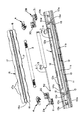
- FIG. 4 is an exploded configuration diagram of the retracting unit 6. It is a top view which shows the state which removed the cover 15 from the drawing-in unit 6.
- FIG. 2 is a schematic perspective view of a slider 2A that constitutes a pull-in unit 6. It is the schematic perspective view which looked at the slider 2A from the direction different from Fig.4 (a).
- FIG. 3 is a schematic perspective view of a slider 2B that constitutes a pull-in unit 6. It is the schematic perspective view which looked at the slider 2B from the direction different from Fig.5 (a).
- FIG. 7 is an enlarged cross-sectional view taken along the line BB shown in FIG. It is an expanded sectional view in the AA section shown in Drawing 6 (c).
- FIG. 7 is an enlarged cross-sectional view taken along the line CC shown in FIG.
- FIG. 1 It is a schematic diagram which shows the application example of the drawing-in unit. It is an exploded view of the protrusion body 8 which is an operation member used for the drawing unit 6. It is a figure which shows the relationship between the frame by the side of the main body, the drawing-in unit 6, and the projection body 8 (operation member). It is a figure which shows the relationship between the frame by the side of the main body, the drawing-in unit 6, and the projection body 8 (operation member). It is a figure which shows the relationship between the frame by the side of the main body, the drawing-in unit 6, and the projection body 8 (operation member). It is the figure which looked at the latch 4 in a stand-by posture from the upper side. It is the figure which looked at the latch 4 in a waiting position from the lower side.
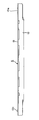
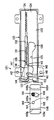
- FIG.1 (a) is a bottom view of the drawing unit 6 used as the principal part of the sliding assistance mechanism which concerns on embodiment of this invention.
- FIG. 1B is a side view of the retracting unit 6
- FIG. 1C is a side view of one side of the retracting unit 6.
- FIG. 2 is an exploded configuration diagram of the retracting unit 6.
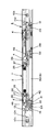
- FIG. 3 is a plan view showing a state where the cover 15 is removed from the retracting unit 6. In FIG. 3, the right latch 4 is in the retracted position.
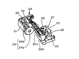
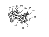
- FIG. 4A is a schematic perspective view of the slider 2A constituting the pull-in unit 6, and FIG. 4B is a schematic perspective view of the slider 2A viewed from a direction different from that in FIG. 4A.
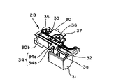
- 5A is a schematic perspective view of the slider 2B constituting the pull-in unit 6, and
- FIG. 5B is a schematic perspective view of the slider 2B viewed from a direction different from that in FIG. 5A.
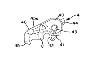
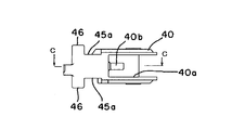
- FIGS. 6A to 6D are a top view, a front view, a bottom view, and a rear view of the latch 4 (latch on the slider 2A side) constituting the pull-in unit 6, respectively.
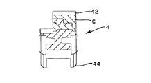
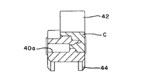
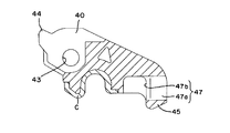
- FIG. 7 (a) is an enlarged cross-sectional view taken along line BB shown in FIG. 6 (c).
- FIG. 7B is an enlarged cross-sectional view taken along the line AA shown in FIG.
- FIG. 7C is an enlarged cross-sectional view taken along the line CC shown in FIG.
- FIG. 8A is a schematic diagram showing an application example of the retracting unit 6.
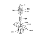
- FIG. 8B is an exploded view of the protrusion 8 that is an operating member used in the retracting unit 6.
- FIGS. 9A to 9C are views showing the relationship between the frame on the main body 7 side, the retracting unit 6 and the protrusions 8 (actuating members).
- 9A is a schematic diagram of the fully opened state in which the sliding door is switched to the open position, and FIG.
- FIG. 9B is a schematic diagram of the fully closed state in which the sliding door is switched to the closed position.
- FIG. 10C is a schematic diagram illustrating a state in which the left latch 4 is in a retracted position due to a malfunction from the state illustrated in FIG.
- FIG. 10A and FIG. 10B are views of the latch 4 in the standby posture as viewed from the upper side and the lower side, respectively.
- FIGS. 11A and 11B are views of the latch 4 in the retracted posture as viewed from the upper side and the lower side, respectively.
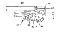
- FIG. 12A is a view schematically showing an operation when the protrusion 8 (actuating member) is engaged with the latch 4 in the retracted position (the state shown in FIG. 9C).
- FIG. 12B is a diagram three-dimensionally showing the operation shown in FIG.
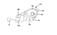
- FIG. 13A is a diagram showing a first modification of the embodiment of the present invention
- FIG. 13B is a diagram showing a second modification of the embodiment of the present invention.
- the mechanism features, the retracting unit, the operating member, the assembly, the main operation, and the modification will be described in detail in this order.
- the sliding assist mechanism of the present invention includes a retracting unit 6 attached to one of the sliding doors A (B) as the main body 7 or a moving body, and a protrusion 8 as an operating member attached to the other of the main body 7 or the sliding door A (B).
- a retracting unit 6 attached to one of the sliding doors A (B) as the main body 7 or a moving body
- a protrusion 8 as an operating member attached to the other of the main body 7 or the sliding door A (B).
- the retracting unit 6 includes the case 1, the slider 2, the latch 4, the urging unit 3, and the braking unit 5.
- the slider 2 and the braking unit 5 can be omitted as in Patent Document 1. is there.
- the main body 7 is, for example, a kitchen or shelf having an opening, or a desk or copying machine having a storage space.
- the moving body is not limited to the sliding doors A and B, and may be a drawer for storage, etc., and is in a closed position (a fully closed position) along the guide rail provided in the opening of the main body 7 or the storage space.
- the drawer it is slidably disposed between the open position (which corresponds to the push-in position) and the open position (which is the fully open position, which corresponds to the drawer position in the drawer).
- the pull-in unit 6 and the protrusion 8 are roughly classified into the following three types depending on the target moving body and pull-in operation settings.
- the pull-in unit 6 includes a pair of sliders 2A and 2B that are slid in directions toward and away from each other, an urging means 3 that urges the sliders 2A and 2B toward each other, and each of the sliders 2A and 2B.
- a pair of latches 4 and 5 that can be held in each other are arranged.
- this configuration is a case in which one of the sliding doors A and B in FIG. 8A as the moving body, for example, a single sliding door A is slid with respect to the corresponding opening of the main body 7. Is moved from the closed position to the open direction and from the open position to the close direction, the urging force of the urging means 3 is then moved to the open position and the closed position.
- the invention of claim 2 is specified by assuming such a configuration.
- the second configuration is a case in which the sliding doors A and B of FIG. 8A are slid with respect to the corresponding openings of the main body 7 as moving bodies.
- FIG. 8A two drawer units 6 and A total of four protrusions 8 were used as a set, but instead of this, component members other than the case 1 of the drawing unit 6 corresponding to the sliding door A and the drawing unit 6 corresponding to the sliding door B are assembled to the common case. (See Japanese Patent Application Publication No. 2008-144567).
- this retracting unit a pair of sliders 2A and 2B slid in directions toward and away from each other, urging means 3 for urging the sliders 2A and 2B toward each other, and each slider 2A , 2B and the sliders 2A, 2B are pivotally supported by the respective sliders 2A, 2B, and the sliders 2A, 2B are separated from each other by being releasably locked to the case 1 side.
- the pair of latches 4 and 4 that can be held in the unit is used as a unit, and these two sets are arranged for the same case. Since this is easy to understand from the following configuration, the description thereof is omitted.
- the third configuration is a case where the moving body is pulled in only one direction as disclosed in Patent Document 1.
- one of the sliders 2A and 2B is omitted in FIG. 3
- one end of the biasing means 3 is locked to the slider and the other end is locked to the case side
- one end of the braking means 5 is It becomes the simplest structure which latches to a slider and latches the other end to a case side.
- the invention of claim 1 is specified by assuming such a configuration. Since this configuration and operation are also easy to understand from the following configuration, a description thereof is omitted.
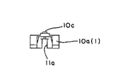
- the case 1 includes a space portion 10 that is open on the upper side and a mounting portion 10 a that protrudes to the left and right of the space portion 10, as shown in FIGS. 1 (a) to 3. And a cover 15 that closes the space 10.
- the space portion 10 has an elongated rectangular container shape and is partitioned by a lower surface 11, both side surfaces 12, and left and right end portions 13.
- the lower surface 11 is provided with a guide hole 11a located in the middle of the width and extending left and right, a slider guide groove 11b having a substantially concave cross section, and a latching guide portion 14 having a substantially L-shaped cross section. .
- the slider guide groove 11b and the latch guide portion 14 are provided so as to face the lower surface of the cover 15 (not shown).
- the guide hole 11a on the lower surface 11 penetrates up and down and guides the protrusion 8 to move into the case.
- the guide groove 11b is a linear groove provided between the end 13 and the end 13 facing each other on one side of the guide hole 11a.
- the guide grooves 11b on the lower surface 11 and the guide grooves on the cover 15 guide the sliding of the sliders 2A and 2B in a state of being fitted to the protrusions 22 or 32 provided on the upper and lower surfaces of the sliders 2A and 2B.
- the guide part 14 is provided along the hole edge of the guide hole 11a on the other side of the guide hole 11a.
- the guide portion 14 of the lower surface 11 and the guide portion of the cover 15 each include a pair of linear grooves 14a parallel to the guide holes 11a, and substantially L-shaped locking grooves 14b provided on both sides of the linear grooves 14a.
- the latch 4 has the convex part 52 provided in the up-and-down surface mentioned later, and guides the sliding of the latch 4 along the linear groove 14a in the state which fitted this convex part 52, And the convex 52 Engages with the locking groove 14b to lock the sliding of the latch 4 (and the slider).
- Reference numeral 12b denotes a streak-like wall portion that defines the locking groove 14, and the wall portion that defines the locking groove 14b is formed one step higher so that the convex portion 52 of the latch 4 is engaged. So that they are not inadvertently unlocked.
- a plurality of pairs of hook-like engaging portions 12a and hole-like engaging portions 17a that are engaged with each other when the cover 15 is disposed in the space portion 10 are provided on both the side surface 12 on the case side and the both sides 17 on the cover side.
- the case-side mounting portion 10b and the cover-side left and right end surfaces 18 are provided with a concave locking portion 10d and a convex engagement piece 18a that engage with each other when the cover 15 is disposed in the space portion 10. Yes.
- the cover 15 is integrated with the case 1 through their engagement.
- the left and right attachment portions 10a have reverse concave shapes in the width direction, and the protrusions 8 can slide along the guide holes 11a from the reverse concave portions.
- the sliders 2A and 2B are arranged in a space between the case-side lower surface 11 and the cover 15, and as shown in FIGS. 2 to 5B, latch support portions 20 and 30 and the support portions. It forms the resin-made block shape which consists of the connection parts 21 and 31 for braking means integrated on one side of this via the connection parts 20a and 30a.
- a piston-type damper type is used as the braking means 5.
- This piston type damper may be any known one (for example, the one described in Japanese Patent Application Publication No. 2006-29564), and has a cylinder 50 and a piston rod 51 that is gently projected and retracted in the cylinder 50. Any configuration may be used as long as it is gently driven with respect to the cylinder 50 to which the piston rod 51 is fixed or gently driven with respect to the piston rod 51 to which the cylinder 50 is fixed.
- the cylinder 50 has a neck-shaped locking groove (not shown) on the outer periphery of the rear end, and the piston rod 51 has a neck-shaped locking groove on the outer periphery of the front end.
- both sliders 2A and 2B have different shapes due to the use of a piston type damper as the braking means 5, but when the rotary damper is used as the braking means, the same shape is set. Is possible.
- the sliders 2A and 2B are different in that the connecting portions 21 and 31 form part of the upper and lower surfaces 2a and 2b or 3a and 3b, and the upper and lower surfaces 2a and 2b of the connecting portion 21 or the upper and lower surfaces 3a and 3b of the connecting portion 34.
- the support portions 20 and 30 are provided on the inner side surface and have arcuate cross-section guide portions 20b and 30b that guide the cylinder 50.
- the point and the support part 20 and 30 are provided in a place that is one step lower than the upper and lower surfaces 2a and 2b or 3a and 3b and have grooves 23 or 33 on the upper and lower surfaces that restrict the movement of the latch 4.
- the support portions 20 and 30 are provided with latching portions 25 or 35 that protrude from the lower upper surface 20 and 30 and lock the corresponding end of the coil spring that is the biasing means 3.
- 10 (a) provided near the groove 23 or 33.
- a shaft portion 26 or 36 that pivotally supports the latch 4 is provided on the upper and lower surfaces, and a plurality of protrusions that protrude from the outer surfaces of the support portions 20 and 30.
- the outer convex portions 28 or 38 provided near the shaft portions 26 or 36 and the grooves 23 or 33 on the lower surface side of the support portions 20 and 30, and the inner small portions. This is common in that it has a convex portion 29.
- the protrusions 22 and 32 extend in a straight line, and fit into the case-side guide groove 11b and the cover 15-side guide groove.
- Each of the grooves 23 and 33 is partitioned by a substantially L-shaped wall portion, and opens on the side facing the shaft portion 26 or 36.
- the latching portions 25 and 35 and the shaft portions 26 and 36 are located on the left and right sides of the grooves 23 and 33.
- the convex portions 28 and 38 are slid along the case side guide hole 11 a, and the small convex portion 29 is slid along the linear groove 14 a of the case side guide portion 14.
- the connecting portion 21 of the slider 2A has an insertion hole 24a provided on the inner end surface and a relief portion 24b cut out from the outside toward the insertion hole 24a.
- the connecting portion 31 of the slider 2B has a substantially U-shaped clamp portion 34a provided with a gap 34a between the inner end surface and the connecting portion 31.
- the latch 4 is assembled to the sliders 2A and 2B so as to be rotatable about the shaft portions 26 and 36 as fulcrums.
- the latch used for the slider 2A and the latch used for the slider 2B are symmetrical.
- 6A to 7C show the latch on the slider 2A side
- FIGS. 10A to 11B show the latch on the slider 2B side.
- the latch 4 is a resin molded body, and includes a support portion 40 that pivots on the slider side, and an engagement portion 42 that is provided on one side of the support portion 40 and engages with the protrusion 8 that is an operation member at a normal time.
- the auxiliary engagement means 47 provided on the lower surface side of the latch and on the distal end 45 side of the engagement portion 42 are integrally formed.
- the support part 40 makes the substantially concave shape which was thinned 40a except the upper and lower parts and the engaging part 42 side, and the protrusion 40b protruded in the concave shape, It has a shaft hole 43 penetratingly formed in the upper and lower portions, and protrusions 44 and 44 respectively extending in the horizontal direction from the upper and lower portions.
- the engaging portion 42 is provided in a substantially U shape on one side of the support portion 40. Further, the location C forming the engaging portion 42 is one step lower on the upper surface side of FIG. 6A, and the lower surface side of FIG. 6C is flush with the outer surface of the support portion 40.
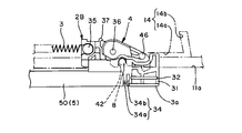
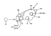
- the auxiliary engagement means 47 engages with the protrusion 8 when the latch 4 is in a non-engaged retracted position due to malfunction, thereby enabling the latch 4 to be switched from the retracted position to the standby position.
- the tip end side of the lower surface of the latch 4 is formed into a stepped shape that is greatly depressed, and the tip side inclined surface guide portion 47 a that guides the protrusion 8.
- a concave portion 47b which is continuous with the inclined surface guide portion 47a and is deepened by one step.
- the slope guide portion 47a has a taper that becomes lower toward the tip. In the usage mode, when the protrusion 8 abuts upward with respect to the slope guide portion 47a, the projection body slides along the slope guide portion 47a while reducing the protrusion amount. The engagement with 47b is maintained.
- the above-described latch 4 is configured such that the portion C forming the engaging portion 42 is made of a material different from the other portions.
- the location C forming the engaging portion 42 is made of a soft resin material that is softer than other locations.
- the latch 4 is molded by a two-color molding method, and a hard resin portion such as ABS (acrylonitrile / butadiene / styrene polymer) in which the latch aggregate (location excluding the location C) is formed by primary molding,
- the portion C forming the engaging portion 42 is a soft resin portion such as a polyester elastomer or a polypropylene elastomer that is secondarily molded.
- the projecting body 8 that is an actuating member can be moved in and out through an urging force with respect to the sliding door A (B) that is a moving body. It is a configuration that reduces the amount of protrusion against the power.
- the structure shown in FIG. 8B includes a protrusion 8, a bottomed cylindrical support portion 38, a biasing spring 37, and a holding member 36. Among these, the protrusion 8 protrudes from the upper end surface of the support portion 38.
- the support portion 38 has a cavity 38a in which the urging spring 37 is disposed, and has a convex portion 38b projecting on the opposite side surface.
- the holding member 36 has a bottomed cylindrical shape, has a mounting portion 36c projecting from the upper periphery of the tube, and has a hole portion 36b on the opposite side surface.
- the support portion 38 is pushed into the hole portion 36a of the holding member 36 with the biasing spring 37 disposed in the support portion 38 with respect to the holding member 36, and the convex portion 38b is engaged with the hole portion 36b.
- the protrusion 8 protrudes to the maximum with the urging force of the urging spring 37 with respect to the holding member 36 together with the support portion 38, and resists the urging force of the urging spring 37 when receiving a downward load, for example. Reduce the protruding amount.
- the protrusion 8 according to the present invention may be configured so as to project up and down via an urging force, for example, a guide shaft configuration disclosed in Japanese Patent Application Publication No. 2007-107301 or similar thereto. It may be configured.
- each latch 4 is rotatably supported with respect to the sliders 2A and 2B by fitting each shaft hole 43 and each shaft portion 26 or each shaft portion 43 and each shaft portion 36.
- the sliders 2 ⁇ / b> A and 2 ⁇ / b> B are connected to each other via a piston type damper that is a braking means 5.
- the piston rod 51 is connected to the connecting portion 21 of the slider 2A with the retaining ring 52 and the like shown in FIG. It is connected by engaging the stop groove.
- the cylinder 50 is connected to the connecting portion 31 of the slider 2B by engaging the cylinder side locking groove with the clamp portion 34.
- the sliders 2A and 2B with the latch 4 described above, the braking means 5, and the biasing means 3 are combined and arranged with respect to the case 1 and covered with the cover 15.
- the slider 2A and the slider 2B fit the corresponding protrusion 22 or protrusion 32 into the case-side guide groove 11, and the case side
- Each latch 4 fits the corresponding convex portion 46 to the guide portion 14, and from this state, the coil spring as the biasing means 3 is disposed between the sliders 2A and 2B. That is, one end of the coil spring is locked to the latching portion 25 of the slider 2A, and the other end is latched to the latching portion 35 of the slider 2B.
- the slider 2A and the slider 2B are separated to the maximum against the biasing force of the biasing means 3, and the convex portion 46 of the latch 4 on the slider 2A side is engaged with the one locking groove 14b. Then, the convex portion 46 of the latch 4 on the slider 2B side is engaged with the other locking groove 14b.
- the latch 4 on the slider 2A side and the latch 4 on the slider 2B side as shown in FIGS. 11 (a) and 11 (b), approach the slider 4 toward the slider side, that is, the attitude toward the slider side. As shown in FIGS.
- the sliders 2 ⁇ / b> A and 2 ⁇ / b> B, the latches 4, the braking means 5, and the biasing means 3 are sandwiched between the case-side lower surface 11 and the cover 15.
- the sliders 2A and 2B are slid with the upper and lower protrusions 22 and 32 fitted in the corresponding guide grooves 11b and maintained in the fitted state.
- Each latch 4 has the above-described pulling posture when the upper and lower convex portions 46 are fitted into the corresponding guide portions 14 and the respective convex portions 46 are fitted into the linear grooves 14a, and the respective convex portions 46 are engaged with the locking grooves 14b. When this occurs, it is switched to the standby posture described above.
- 9 (a) to 9 (c) schematically show the case where the above sliding assist mechanism is applied to the sliding door shown in FIG. 8 (a).
- Reference numeral 70 denotes an opening on the main body 7 side.
- the upper side guide rail of the sliding door frame provided in the section is assumed.
- 9A shows a state in which the opening portions of the sliding doors A and B are fully opened
- FIG. 9B shows a state in which the opening portions of the sliding doors A and B are fully closed.
- the schematic positional relationship of each protrusion 8 provided in the sliding doors A and B is shown.
- the protrusion 2 of the slider 2A is guided along the guide groove 11b, and the protrusion 46 of the latch 4 is guided along the linear groove 14a.
- the sliding door B is also switched to the closed position in the same manner as the sliding door A. Further, in this embodiment, when the sliding doors A and B are moved by the urging force of the urging means 3, the sliding doors A and B are slid gently under the braking force of the braking means 5.
- the sliding door B is also switched to the closed position in the same manner as the sliding door A.
- the sliding doors A and B are moved by the urging force of the urging means 3, the sliding doors A and B are slid gently under the braking force of the braking means 4.
- FIG. 9C shows, for example, when the sliding door A starts to move in the direction of the arrow (right side) from the state of FIG. It is assumed that the lock is inadvertently released. In this embodiment, when such a malfunction occurs, the auxiliary engagement means 7 can easily restore the normal state.
- the sliding door A is further moved in the direction of the arrow, that is, the sliding door A is moved to a position slightly before the state shown in FIG.
- the latch 4 on the slider 2A side is in the retracted position as shown in FIGS. 12 (a) and 12 (b).
- the left projection 8 provided on the sliding door A enters the slope guide portion 47a of the auxiliary engagement means 7 as shown in FIG. 12A, and the slope guide portion 47a.
- the projection amount is increased again to engage with the recessed portion 47b that is deeper one step.
- the sliding door A is moved to the left as shown in FIG.
- the protrusion 8 is moved in and out by the biasing spring 37 (once the biasing force of the biasing spring 37).
- the protrusion amount is reduced against this, and the protrusion amount is increased again by the urging force).
- the latch 4 of the slider 2A is rotated clockwise around the shaft portion 26 by the reaction force when the engagement is released, and the convex portion 46 engages with the locking groove 14b and is switched to the standby posture.
- FIGS. 13A and 13B show a modification of the auxiliary engagement means 47 having the above-described repair structure.
- the same parts as those in the above embodiment are given the same reference numerals, and only the changes are clarified.
- the latch 4A shown in FIG. 13A has an engagement hole 48 that is provided on the distal end side and elastically engages and disengages the protrusion 8.
- the protrusion 8 may be a simple shaft or pin, but the setting of the degree of engagement or the engagement strength of the protrusion 8 with respect to the engagement hole 48 is important.
- the latch 4B shown in FIG. 13B has a magnet 49 that is provided on the tip side and attaches and detaches the protrusion 8 with a magnetic force.
- the protrusion 8 may be a simple metal shaft or pin, but the setting of the degree of adsorption between the magnet 4 and the protrusion 8 is important.
- the above-described latch is constituted by a latch body and a divided portion by dividing the leading end side of the latch. Further, the dividing portion pivotally supports the latch body so as to be rotatable and elastically returnable. When the protrusion 8 hits the split portion, the split portion is inverted against the urging force, so that the protrusion 8 can be engaged with the engaging portion 42.
- the present invention can be modified as appropriate except for the requirements specified in the claims.
Landscapes
- Vehicle Step Arrangements And Article Storage (AREA)
- Closing And Opening Devices For Wings, And Checks For Wings (AREA)
- Piles And Underground Anchors (AREA)
- Drawers Of Furniture (AREA)
- Lock And Its Accessories (AREA)
Priority Applications (4)
| Application Number | Priority Date | Filing Date | Title |
|---|---|---|---|
| CN200980120727.0A CN102057121B (zh) | 2008-06-06 | 2009-06-05 | 滑动辅助机构 |
| EP20090758418 EP2317056A4 (de) | 2008-06-06 | 2009-06-05 | Gleitunterstützungsmechanismus |
| US12/737,014 US20110138579A1 (en) | 2008-06-06 | 2009-06-05 | Sliding assist mechanism |
| KR1020107029129A KR101200158B1 (ko) | 2008-06-06 | 2009-06-05 | 슬라이딩 보조기구 |
Applications Claiming Priority (2)
| Application Number | Priority Date | Filing Date | Title |
|---|---|---|---|
| JP2008149908A JP5294714B2 (ja) | 2008-06-06 | 2008-06-06 | 摺動補助機構 |
| JP2008-149908 | 2008-06-06 |
Publications (1)
| Publication Number | Publication Date |
|---|---|
| WO2009148151A1 true WO2009148151A1 (ja) | 2009-12-10 |
Family
ID=41398224
Family Applications (1)
| Application Number | Title | Priority Date | Filing Date |
|---|---|---|---|
| PCT/JP2009/060337 Ceased WO2009148151A1 (ja) | 2008-06-06 | 2009-06-05 | 摺動補助機構 |
Country Status (6)
| Country | Link |
|---|---|
| US (1) | US20110138579A1 (de) |
| EP (1) | EP2317056A4 (de) |
| JP (1) | JP5294714B2 (de) |
| KR (1) | KR101200158B1 (de) |
| CN (1) | CN102057121B (de) |
| WO (1) | WO2009148151A1 (de) |
Cited By (5)
| Publication number | Priority date | Publication date | Assignee | Title |
|---|---|---|---|---|
| JP2012144891A (ja) * | 2011-01-11 | 2012-08-02 | Shibutani:Kk | 可動体の自走機構 |
| US20130014343A1 (en) * | 2010-03-17 | 2013-01-17 | Nifco Inc. | Slide assist device |
| US20130019438A1 (en) * | 2010-03-17 | 2013-01-24 | Nifco Inc. | Slide assist device |
| CN102918223A (zh) * | 2010-05-31 | 2013-02-06 | 株式会社利富高 | 移动辅助装置 |
| EP4484691A4 (de) * | 2023-05-08 | 2025-04-09 | Ideal Sanitary Ware Co., Ltd. | Bidirektionaler puffer |
Families Citing this family (7)
| Publication number | Priority date | Publication date | Assignee | Title |
|---|---|---|---|---|
| JP2012127139A (ja) * | 2010-12-16 | 2012-07-05 | Nifco Inc | 摺動補助装置 |
| JP5679309B2 (ja) * | 2011-03-16 | 2015-03-04 | 株式会社Skb | 引戸のアシスト装置 |
| KR101319534B1 (ko) * | 2013-04-24 | 2013-10-21 | 김종천 | 유동걸림부를 갖는 개폐구용 완충장치 |
| DE102015003424B3 (de) | 2015-03-17 | 2016-07-07 | Günther Zimmer | Geräuscharme Einzugsvorrichtung und Schiebetüranordnung |
| DE102015003415B3 (de) * | 2015-03-17 | 2016-02-25 | Günther Zimmer | Beschleunigungs- und Verzögerungsvorrichtung mit geräuscharmer Bewegung |
| DE102017123613A1 (de) * | 2017-10-11 | 2019-04-11 | Paul Hettich Gmbh & Co. Kg | Einzugsvorrichtung und Verfahren zum Öffnen und Schließen eines bewegbaren Möbelteils |
| JP7723945B1 (ja) * | 2024-07-31 | 2025-08-15 | 高千穂交易株式会社 | 構造体及び構造システム |
Citations (6)
| Publication number | Priority date | Publication date | Assignee | Title |
|---|---|---|---|---|
| JP2005290769A (ja) | 2004-03-31 | 2005-10-20 | Murakoshi Mfg Corp | 部材保持装置 |
| JP2006029564A (ja) | 2004-07-21 | 2006-02-02 | Nifco Inc | 移動体の衝撃吸収装置 |
| JP2006200301A (ja) * | 2005-01-24 | 2006-08-03 | Tostem Corp | 引戸の引き込み装置 |
| JP2007107301A (ja) | 2005-10-14 | 2007-04-26 | Murakoshi Mfg Corp | 引戸などのガイド装置 |
| JP2008144567A (ja) | 2006-11-13 | 2008-06-26 | Nifco Inc | 摺動補助機構及び引込ユニット |
| JP2008149908A (ja) | 2006-12-18 | 2008-07-03 | Toyota Motor Corp | ハイブリッド駆動装置 |
Family Cites Families (63)
| Publication number | Priority date | Publication date | Assignee | Title |
|---|---|---|---|---|
| US5207781A (en) * | 1989-04-03 | 1993-05-04 | Julius Blum Gesellschaft M.B.H. | Closing device for moving a drawer to a fully inserted position within a furniture body |
| DE69310790T2 (de) * | 1992-03-16 | 1998-01-02 | Kato Hatsujo Kaisha Ltd | Sicherheitsverriegelung für ein Fahrzeugablagefach |
| AT401717B (de) * | 1993-06-23 | 1996-11-25 | Blum Gmbh Julius | Schliessvorrichtung für schubladen |
| US5448797A (en) * | 1993-10-15 | 1995-09-12 | Von Duprin, Inc. | Selectable friction assisted door holder assembly |
| AT407602B (de) * | 1994-08-31 | 2001-05-25 | Alfit Ag | Einzugsvorrichtung für schubladen |
| DE19835466B4 (de) * | 1998-08-06 | 2004-08-05 | Grass Ges.m.b.H., Metallwarenfabrik, Höchst | Bremsvorrichtung mit Schließfolgeregler für bewegliche Möbelteile |
| US6487752B1 (en) * | 2000-03-21 | 2002-12-03 | David S. Mathews | Sliding door stop |
| CN2414153Y (zh) * | 2000-04-19 | 2001-01-10 | 陈鼎凌 | 自动伸缩门开门机支架锁定机构 |
| CN2437816Y (zh) * | 2000-08-11 | 2001-07-04 | 卢耀骚 | 推拉门窗中间自动锁 |
| IT250443Y1 (it) * | 2000-09-19 | 2003-09-10 | Salice Arturo Spa | Dispositivo per la chiusura decelerata di parti di mobile scorrevoli |
| US6375290B1 (en) * | 2001-09-28 | 2002-04-23 | King Slide Works Co., Ltd. | Lock snap structure of slide rail |
| US6848759B2 (en) * | 2002-04-03 | 2005-02-01 | Illinois Tool Works Inc. | Self-closing slide mechanism with damping |
| MY131087A (en) * | 2002-05-17 | 2007-07-31 | Harn Marketing Sdn Bhd | Closing device for drawers |
| US6910557B2 (en) * | 2003-01-29 | 2005-06-28 | Illinois Tool Works Inc. | Slide damper with spring assist |
| AT413187B (de) * | 2003-04-25 | 2005-12-15 | Blum Gmbh Julius | Einzugsvorrichtung für schubladen |
| TWM244806U (en) * | 2003-05-15 | 2004-10-01 | King Slide Works Co Ltd | Automatic return device for sliding rail |
| DE20311795U1 (de) * | 2003-07-31 | 2004-11-18 | Alfit Ag | Schubladen-Ausziehführung mit Einzugsautomatik mit integrierter Dämpfung |
| US6979066B2 (en) * | 2003-10-29 | 2005-12-27 | Jun-Long Yang | Rail assembly for furniture |
| US6997528B2 (en) * | 2003-10-29 | 2006-02-14 | Jun-Long Yang | Rail assembly for furniture |
| ITMC20030144A1 (it) * | 2003-12-05 | 2005-06-06 | Compagnucci Spa Ora Compagnucci Ho Lding Spa | Dispositivo per la chiusura automatica ed ammortizzata dei cassetti e delle strutture estraibili per mobili. |
| TWI231749B (en) * | 2003-12-24 | 2005-05-01 | Mau-Chin Shen | Restoring/positioning device for slide rail of drawer |
| WO2005068760A1 (ja) * | 2004-01-13 | 2005-07-28 | K.K. Murakoshi Seikoh | 緩衝装置 |
| US7077487B2 (en) * | 2004-02-24 | 2006-07-18 | Jun-Long Yang | Drawer rail with auto-returning device |
| JP4459679B2 (ja) * | 2004-03-30 | 2010-04-28 | 株式会社ニフコ | 摺動補助装置 |
| AT503045B1 (de) * | 2004-06-18 | 2008-01-15 | Blum Gmbh Julius | Vorrichtung zum bewegen eines bewegbaren möbelteils |
| JP4446825B2 (ja) * | 2004-07-21 | 2010-04-07 | 株式会社ニフコ | スライド補助装置 |
| JP4446823B2 (ja) * | 2004-07-21 | 2010-04-07 | 株式会社ニフコ | 摺動補助装置 |
| JP4446824B2 (ja) * | 2004-07-21 | 2010-04-07 | 株式会社ニフコ | スライド補助装置 |
| KR100600172B1 (ko) * | 2004-08-30 | 2006-07-12 | 주영전자(주) | 슬라이드레일의 자동닫힘 및 열림방지장치 |
| DE202005009860U1 (de) * | 2004-12-17 | 2006-04-20 | Alfit Ag | Schließ- und Öffnungsvorrichtung für Schubladen |
| JP4751607B2 (ja) * | 2004-12-20 | 2011-08-17 | 株式会社ニフコ | 自走往動させる機構、引き戸機構、および、引き出し機構 |
| JP4601503B2 (ja) * | 2005-07-08 | 2010-12-22 | 株式会社ムラコシ精工 | 緩衝装置、開閉装置 |
| CN2839510Y (zh) * | 2005-08-15 | 2006-11-22 | 洪国民 | 一种自动关门机构 |
| US7533946B2 (en) * | 2005-08-25 | 2009-05-19 | Knape & Vogt Manufacturing Company | Closing device for drawers |
| TWM287625U (en) * | 2005-11-07 | 2006-02-21 | Nan Juen Int Co Ltd | Automatic retracting mechanism for sliding rail of drawer |
| JP4806609B2 (ja) * | 2005-11-21 | 2011-11-02 | トックベアリング株式会社 | 引き込みユニット |
| CN2835491Y (zh) * | 2005-11-22 | 2006-11-08 | 张冠华 | 滑动机构的随意停自动关闭装置 |
| TWM299510U (en) * | 2006-02-08 | 2006-10-21 | Nan Juen Int Co Ltd | Linkage mutual-locking mechanism for slide rail of drawer |
| EP1817983A1 (de) * | 2006-02-13 | 2007-08-15 | Grass GmbH | Vorrichtung zur Beeinflussung der Bewegung von relativ zueinander bewegbaren Möbelteilen und Schubladenführung sowie Verfahren zu deren Herstellung |
| KR101129567B1 (ko) * | 2006-03-27 | 2012-03-28 | 박윤식 | 자동폐쇄장치 |
| TWM302606U (en) * | 2006-06-02 | 2006-12-11 | Gslide Corp | Automatic closing equipment for hidden drawer rail |
| TWM300487U (en) * | 2006-06-08 | 2006-11-11 | Gslide Corp | Automatic closing device of drawer rail |
| US20080061663A1 (en) * | 2006-09-08 | 2008-03-13 | Tsung-Che Wu | Drawer slide module structure |
| US7815267B1 (en) * | 2006-09-15 | 2010-10-19 | Gus Frousiakis | Drawer slide closure apparatus |
| US20080100190A1 (en) * | 2006-11-01 | 2008-05-01 | Jui-Lien Yang | Auto-returning track device |
| US7465000B2 (en) * | 2006-11-09 | 2008-12-16 | Nan Juen International Co., Ltd. | Automatic drawer slide homing apparatus |
| US7374261B1 (en) * | 2006-12-08 | 2008-05-20 | Dynaslide Corporation | Push-open type slide structure |
| DE102006058639B4 (de) * | 2006-12-11 | 2008-08-14 | Zimmer, Günther | Kombinierte Verzögerungs- und Beschleunigungsvorrichtung |
| DE102007008363B3 (de) * | 2007-02-16 | 2008-09-18 | Zimmer, Günther | Zugvorrichtung mit ab- oder umgelenkter Zugfeder |
| TWI321996B (en) * | 2007-02-17 | 2010-03-21 | King Slide Works Co Ltd | Slide assembly having an automatic retractable device |
| US7784890B1 (en) * | 2007-10-03 | 2010-08-31 | Gslide Corporation | Biaxial flow damper for drawer |
| US8052232B1 (en) * | 2007-10-03 | 2011-11-08 | KV IP Holdings Ltd. | Biaxial flow damper for drawer |
| US7980640B2 (en) * | 2007-11-08 | 2011-07-19 | Jun-Long Yang | Auto-return drawer rail |
| US7600828B2 (en) * | 2007-12-20 | 2009-10-13 | King Slide Works Co., Ltd. | Slide assembly having a homing device |
| DE102008021458A1 (de) * | 2008-04-29 | 2010-01-07 | Zimmer, Günther | Beschleunigungsvorrichtung mit zwei Energiespeichern |
| US8060983B2 (en) * | 2008-09-25 | 2011-11-22 | Bortoluzzi Mobili S.R.L. | Device for cushioning an opening and closing movement of sliding shutters |
| TWI392465B (zh) * | 2008-11-20 | 2013-04-11 | King Slide Works Co Ltd | 用於滑軌組件之自動回歸裝置 |
| US8113607B2 (en) * | 2009-05-08 | 2012-02-14 | Steelcase Inc. | Storage assembly |
| JP2011006872A (ja) * | 2009-06-24 | 2011-01-13 | Nifco Inc | 摺動補助機構及び引込ユニット |
| US8307497B2 (en) * | 2010-01-14 | 2012-11-13 | Door & Window Hardware Co. | Soft-closing device for a sliding door |
| US8459758B2 (en) * | 2010-01-21 | 2013-06-11 | Actron Manufacturing, Inc. | Drawer slide auto-close dampening system with reset feature |
| US8240788B2 (en) * | 2010-03-04 | 2012-08-14 | Sun Chain Metal Industry Co., Ltd. | Hidden self-closing drawer slide assembly |
| US8256853B2 (en) * | 2010-03-29 | 2012-09-04 | King Slide Works Co., Ltd. | Opening device for a slide assembly |
-
2008
- 2008-06-06 JP JP2008149908A patent/JP5294714B2/ja active Active
-
2009
- 2009-06-05 WO PCT/JP2009/060337 patent/WO2009148151A1/ja not_active Ceased
- 2009-06-05 KR KR1020107029129A patent/KR101200158B1/ko not_active Expired - Fee Related
- 2009-06-05 US US12/737,014 patent/US20110138579A1/en not_active Abandoned
- 2009-06-05 EP EP20090758418 patent/EP2317056A4/de not_active Withdrawn
- 2009-06-05 CN CN200980120727.0A patent/CN102057121B/zh not_active Expired - Fee Related
Patent Citations (6)
| Publication number | Priority date | Publication date | Assignee | Title |
|---|---|---|---|---|
| JP2005290769A (ja) | 2004-03-31 | 2005-10-20 | Murakoshi Mfg Corp | 部材保持装置 |
| JP2006029564A (ja) | 2004-07-21 | 2006-02-02 | Nifco Inc | 移動体の衝撃吸収装置 |
| JP2006200301A (ja) * | 2005-01-24 | 2006-08-03 | Tostem Corp | 引戸の引き込み装置 |
| JP2007107301A (ja) | 2005-10-14 | 2007-04-26 | Murakoshi Mfg Corp | 引戸などのガイド装置 |
| JP2008144567A (ja) | 2006-11-13 | 2008-06-26 | Nifco Inc | 摺動補助機構及び引込ユニット |
| JP2008149908A (ja) | 2006-12-18 | 2008-07-03 | Toyota Motor Corp | ハイブリッド駆動装置 |
Non-Patent Citations (1)
| Title |
|---|
| See also references of EP2317056A4 |
Cited By (7)
| Publication number | Priority date | Publication date | Assignee | Title |
|---|---|---|---|---|
| US20130014343A1 (en) * | 2010-03-17 | 2013-01-17 | Nifco Inc. | Slide assist device |
| US20130019438A1 (en) * | 2010-03-17 | 2013-01-24 | Nifco Inc. | Slide assist device |
| US8671520B2 (en) * | 2010-03-17 | 2014-03-18 | Nifco Inc. | Slide assist device |
| CN102918223A (zh) * | 2010-05-31 | 2013-02-06 | 株式会社利富高 | 移动辅助装置 |
| CN102918223B (zh) * | 2010-05-31 | 2015-09-02 | 株式会社利富高 | 移动辅助装置 |
| JP2012144891A (ja) * | 2011-01-11 | 2012-08-02 | Shibutani:Kk | 可動体の自走機構 |
| EP4484691A4 (de) * | 2023-05-08 | 2025-04-09 | Ideal Sanitary Ware Co., Ltd. | Bidirektionaler puffer |
Also Published As
| Publication number | Publication date |
|---|---|
| EP2317056A1 (de) | 2011-05-04 |
| KR20110010818A (ko) | 2011-02-07 |
| CN102057121A (zh) | 2011-05-11 |
| CN102057121B (zh) | 2015-04-29 |
| US20110138579A1 (en) | 2011-06-16 |
| EP2317056A4 (de) | 2014-01-22 |
| KR101200158B1 (ko) | 2012-11-12 |
| JP2009293323A (ja) | 2009-12-17 |
| JP5294714B2 (ja) | 2013-09-18 |
Similar Documents
| Publication | Publication Date | Title |
|---|---|---|
| WO2009148151A1 (ja) | 摺動補助機構 | |
| JP5093881B2 (ja) | 摺動補助機構及び引込ユニット | |
| JP5433466B2 (ja) | 摺動補助装置 | |
| WO2010150863A1 (ja) | 摺動補助機構及び引込ユニット | |
| JP5823792B2 (ja) | ロック装置 | |
| EP2776651B1 (de) | Schlossvorrichtung mit einer mehrteiligen sperrklinke | |
| US7708357B2 (en) | Automatic locking apparatus used in guide rail for drawer | |
| US20060255596A1 (en) | Flush handle latch mechanism | |
| JP2011196015A (ja) | 摺動補助装置 | |
| JP5497833B2 (ja) | 摺動補助機構 | |
| JP5105629B2 (ja) | 摺動補助機構及び引込ユニット | |
| JP4966883B2 (ja) | 開閉補助機構 | |
| JP3142615U (ja) | 錠前 | |
| JP5628958B2 (ja) | 摺動補助機構 | |
| JP5606799B2 (ja) | 摺動補助機構及び戸首付き引戸 | |
| KR20110037094A (ko) | 자동차용 글로브박스의 개폐장치 | |
| JPH09195608A (ja) | 係止構造 | |
| JP2012127139A (ja) | 摺動補助装置 | |
| JP2015214867A (ja) | 摺動補助装置 |
Legal Events
| Date | Code | Title | Description |
|---|---|---|---|
| WWE | Wipo information: entry into national phase |
Ref document number: 200980120727.0 Country of ref document: CN |
|
| 121 | Ep: the epo has been informed by wipo that ep was designated in this application |
Ref document number: 09758418 Country of ref document: EP Kind code of ref document: A1 |
|
| NENP | Non-entry into the national phase |
Ref country code: DE |
|
| ENP | Entry into the national phase |
Ref document number: 20107029129 Country of ref document: KR Kind code of ref document: A |
|
| REEP | Request for entry into the european phase |
Ref document number: 2009758418 Country of ref document: EP |
|
| WWE | Wipo information: entry into national phase |
Ref document number: 2009758418 Country of ref document: EP |
|
| WWE | Wipo information: entry into national phase |
Ref document number: 12737014 Country of ref document: US |