WO2009151137A1 - エンジン、車両、船舶、およびエンジンの排ガス浄化方法 - Google Patents
エンジン、車両、船舶、およびエンジンの排ガス浄化方法 Download PDFInfo
- Publication number
- WO2009151137A1 WO2009151137A1 PCT/JP2009/060855 JP2009060855W WO2009151137A1 WO 2009151137 A1 WO2009151137 A1 WO 2009151137A1 JP 2009060855 W JP2009060855 W JP 2009060855W WO 2009151137 A1 WO2009151137 A1 WO 2009151137A1
- Authority
- WO
- WIPO (PCT)
- Prior art keywords
- exhaust
- exhaust gas
- passage
- shock wave
- exhaust passage
- Prior art date
- Legal status (The legal status is an assumption and is not a legal conclusion. Google has not performed a legal analysis and makes no representation as to the accuracy of the status listed.)
- Ceased
Links
Images




Classifications
-
- F—MECHANICAL ENGINEERING; LIGHTING; HEATING; WEAPONS; BLASTING
- F01—MACHINES OR ENGINES IN GENERAL; ENGINE PLANTS IN GENERAL; STEAM ENGINES
- F01N—GAS-FLOW SILENCERS OR EXHAUST APPARATUS FOR MACHINES OR ENGINES IN GENERAL; GAS-FLOW SILENCERS OR EXHAUST APPARATUS FOR INTERNAL-COMBUSTION ENGINES
- F01N1/00—Silencing apparatus characterised by method of silencing
- F01N1/06—Silencing apparatus characterised by method of silencing by using interference effect
-
- F—MECHANICAL ENGINEERING; LIGHTING; HEATING; WEAPONS; BLASTING
- F01—MACHINES OR ENGINES IN GENERAL; ENGINE PLANTS IN GENERAL; STEAM ENGINES
- F01N—GAS-FLOW SILENCERS OR EXHAUST APPARATUS FOR MACHINES OR ENGINES IN GENERAL; GAS-FLOW SILENCERS OR EXHAUST APPARATUS FOR INTERNAL-COMBUSTION ENGINES
- F01N1/00—Silencing apparatus characterised by method of silencing
- F01N1/003—Silencing apparatus characterised by method of silencing by using dead chambers communicating with exhaust gas flow passages
-
- F—MECHANICAL ENGINEERING; LIGHTING; HEATING; WEAPONS; BLASTING
- F01—MACHINES OR ENGINES IN GENERAL; ENGINE PLANTS IN GENERAL; STEAM ENGINES
- F01N—GAS-FLOW SILENCERS OR EXHAUST APPARATUS FOR MACHINES OR ENGINES IN GENERAL; GAS-FLOW SILENCERS OR EXHAUST APPARATUS FOR INTERNAL-COMBUSTION ENGINES
- F01N1/00—Silencing apparatus characterised by method of silencing
- F01N1/02—Silencing apparatus characterised by method of silencing by using resonance
-
- F—MECHANICAL ENGINEERING; LIGHTING; HEATING; WEAPONS; BLASTING
- F01—MACHINES OR ENGINES IN GENERAL; ENGINE PLANTS IN GENERAL; STEAM ENGINES
- F01N—GAS-FLOW SILENCERS OR EXHAUST APPARATUS FOR MACHINES OR ENGINES IN GENERAL; GAS-FLOW SILENCERS OR EXHAUST APPARATUS FOR INTERNAL-COMBUSTION ENGINES
- F01N1/00—Silencing apparatus characterised by method of silencing
- F01N1/02—Silencing apparatus characterised by method of silencing by using resonance
- F01N1/023—Helmholtz resonators
-
- F—MECHANICAL ENGINEERING; LIGHTING; HEATING; WEAPONS; BLASTING
- F01—MACHINES OR ENGINES IN GENERAL; ENGINE PLANTS IN GENERAL; STEAM ENGINES
- F01N—GAS-FLOW SILENCERS OR EXHAUST APPARATUS FOR MACHINES OR ENGINES IN GENERAL; GAS-FLOW SILENCERS OR EXHAUST APPARATUS FOR INTERNAL-COMBUSTION ENGINES
- F01N1/00—Silencing apparatus characterised by method of silencing
- F01N1/14—Silencing apparatus characterised by method of silencing by adding air to exhaust gases
-
- F—MECHANICAL ENGINEERING; LIGHTING; HEATING; WEAPONS; BLASTING
- F01—MACHINES OR ENGINES IN GENERAL; ENGINE PLANTS IN GENERAL; STEAM ENGINES
- F01N—GAS-FLOW SILENCERS OR EXHAUST APPARATUS FOR MACHINES OR ENGINES IN GENERAL; GAS-FLOW SILENCERS OR EXHAUST APPARATUS FOR INTERNAL-COMBUSTION ENGINES
- F01N13/00—Exhaust or silencing apparatus characterised by constructional features
- F01N13/009—Exhaust or silencing apparatus characterised by constructional features having two or more separate purifying devices arranged in series
-
- F—MECHANICAL ENGINEERING; LIGHTING; HEATING; WEAPONS; BLASTING
- F01—MACHINES OR ENGINES IN GENERAL; ENGINE PLANTS IN GENERAL; STEAM ENGINES
- F01N—GAS-FLOW SILENCERS OR EXHAUST APPARATUS FOR MACHINES OR ENGINES IN GENERAL; GAS-FLOW SILENCERS OR EXHAUST APPARATUS FOR INTERNAL-COMBUSTION ENGINES
- F01N13/00—Exhaust or silencing apparatus characterised by constructional features
- F01N13/08—Other arrangements or adaptations of exhaust conduits
-
- F—MECHANICAL ENGINEERING; LIGHTING; HEATING; WEAPONS; BLASTING
- F01—MACHINES OR ENGINES IN GENERAL; ENGINE PLANTS IN GENERAL; STEAM ENGINES
- F01N—GAS-FLOW SILENCERS OR EXHAUST APPARATUS FOR MACHINES OR ENGINES IN GENERAL; GAS-FLOW SILENCERS OR EXHAUST APPARATUS FOR INTERNAL-COMBUSTION ENGINES
- F01N13/00—Exhaust or silencing apparatus characterised by constructional features
- F01N13/08—Other arrangements or adaptations of exhaust conduits
- F01N13/10—Other arrangements or adaptations of exhaust conduits of exhaust manifolds
-
- F—MECHANICAL ENGINEERING; LIGHTING; HEATING; WEAPONS; BLASTING
- F01—MACHINES OR ENGINES IN GENERAL; ENGINE PLANTS IN GENERAL; STEAM ENGINES
- F01N—GAS-FLOW SILENCERS OR EXHAUST APPARATUS FOR MACHINES OR ENGINES IN GENERAL; GAS-FLOW SILENCERS OR EXHAUST APPARATUS FOR INTERNAL-COMBUSTION ENGINES
- F01N3/00—Exhaust or silencing apparatus having means for purifying, rendering innocuous, or otherwise treating exhaust
- F01N3/02—Exhaust or silencing apparatus having means for purifying, rendering innocuous, or otherwise treating exhaust for cooling, or for removing solid constituents of, exhaust
-
- F—MECHANICAL ENGINEERING; LIGHTING; HEATING; WEAPONS; BLASTING
- F01—MACHINES OR ENGINES IN GENERAL; ENGINE PLANTS IN GENERAL; STEAM ENGINES
- F01N—GAS-FLOW SILENCERS OR EXHAUST APPARATUS FOR MACHINES OR ENGINES IN GENERAL; GAS-FLOW SILENCERS OR EXHAUST APPARATUS FOR INTERNAL-COMBUSTION ENGINES
- F01N3/00—Exhaust or silencing apparatus having means for purifying, rendering innocuous, or otherwise treating exhaust
- F01N3/08—Exhaust or silencing apparatus having means for purifying, rendering innocuous, or otherwise treating exhaust for rendering innocuous
- F01N3/10—Exhaust or silencing apparatus having means for purifying, rendering innocuous, or otherwise treating exhaust for rendering innocuous by thermal or catalytic conversion of noxious components of exhaust
- F01N3/24—Exhaust or silencing apparatus having means for purifying, rendering innocuous, or otherwise treating exhaust for rendering innocuous by thermal or catalytic conversion of noxious components of exhaust characterised by constructional aspects of converting apparatus
- F01N3/30—Arrangements for supply of additional air
-
- F—MECHANICAL ENGINEERING; LIGHTING; HEATING; WEAPONS; BLASTING
- F01—MACHINES OR ENGINES IN GENERAL; ENGINE PLANTS IN GENERAL; STEAM ENGINES
- F01N—GAS-FLOW SILENCERS OR EXHAUST APPARATUS FOR MACHINES OR ENGINES IN GENERAL; GAS-FLOW SILENCERS OR EXHAUST APPARATUS FOR INTERNAL-COMBUSTION ENGINES
- F01N3/00—Exhaust or silencing apparatus having means for purifying, rendering innocuous, or otherwise treating exhaust
- F01N3/08—Exhaust or silencing apparatus having means for purifying, rendering innocuous, or otherwise treating exhaust for rendering innocuous
- F01N3/10—Exhaust or silencing apparatus having means for purifying, rendering innocuous, or otherwise treating exhaust for rendering innocuous by thermal or catalytic conversion of noxious components of exhaust
- F01N3/24—Exhaust or silencing apparatus having means for purifying, rendering innocuous, or otherwise treating exhaust for rendering innocuous by thermal or catalytic conversion of noxious components of exhaust characterised by constructional aspects of converting apparatus
- F01N3/30—Arrangements for supply of additional air
- F01N3/34—Arrangements for supply of additional air using air conduits or jet air pumps, e.g. near the engine exhaust port
-
- F—MECHANICAL ENGINEERING; LIGHTING; HEATING; WEAPONS; BLASTING
- F02—COMBUSTION ENGINES; HOT-GAS OR COMBUSTION-PRODUCT ENGINE PLANTS
- F02B—INTERNAL-COMBUSTION PISTON ENGINES; COMBUSTION ENGINES IN GENERAL
- F02B27/00—Use of kinetic or wave energy of charge in induction systems, or of combustion residues in exhaust systems, for improving quantity of charge or for increasing removal of combustion residues
- F02B27/04—Use of kinetic or wave energy of charge in induction systems, or of combustion residues in exhaust systems, for improving quantity of charge or for increasing removal of combustion residues in exhaust systems only, e.g. for sucking-off combustion gases
-
- F—MECHANICAL ENGINEERING; LIGHTING; HEATING; WEAPONS; BLASTING
- F01—MACHINES OR ENGINES IN GENERAL; ENGINE PLANTS IN GENERAL; STEAM ENGINES
- F01N—GAS-FLOW SILENCERS OR EXHAUST APPARATUS FOR MACHINES OR ENGINES IN GENERAL; GAS-FLOW SILENCERS OR EXHAUST APPARATUS FOR INTERNAL-COMBUSTION ENGINES
- F01N1/00—Silencing apparatus characterised by method of silencing
- F01N1/08—Silencing apparatus characterised by method of silencing by reducing exhaust energy by throttling or whirling
- F01N1/085—Silencing apparatus characterised by method of silencing by reducing exhaust energy by throttling or whirling throttling exhaust gas flow using a central core in a flow passage
-
- F—MECHANICAL ENGINEERING; LIGHTING; HEATING; WEAPONS; BLASTING
- F01—MACHINES OR ENGINES IN GENERAL; ENGINE PLANTS IN GENERAL; STEAM ENGINES
- F01N—GAS-FLOW SILENCERS OR EXHAUST APPARATUS FOR MACHINES OR ENGINES IN GENERAL; GAS-FLOW SILENCERS OR EXHAUST APPARATUS FOR INTERNAL-COMBUSTION ENGINES
- F01N2240/00—Combination or association of two or more different exhaust treating devices, or of at least one such device with an auxiliary device, not covered by indexing codes F01N2230/00 or F01N2250/00, one of the devices being
- F01N2240/26—Combination or association of two or more different exhaust treating devices, or of at least one such device with an auxiliary device, not covered by indexing codes F01N2230/00 or F01N2250/00, one of the devices being an exhaust gas reservoir, e.g. emission buffer
-
- F—MECHANICAL ENGINEERING; LIGHTING; HEATING; WEAPONS; BLASTING
- F01—MACHINES OR ENGINES IN GENERAL; ENGINE PLANTS IN GENERAL; STEAM ENGINES
- F01N—GAS-FLOW SILENCERS OR EXHAUST APPARATUS FOR MACHINES OR ENGINES IN GENERAL; GAS-FLOW SILENCERS OR EXHAUST APPARATUS FOR INTERNAL-COMBUSTION ENGINES
- F01N2470/00—Structure or shape of exhaust gas passages, pipes or tubes
- F01N2470/20—Dimensional characteristics of tubes, e.g. length, diameter
-
- F—MECHANICAL ENGINEERING; LIGHTING; HEATING; WEAPONS; BLASTING
- F01—MACHINES OR ENGINES IN GENERAL; ENGINE PLANTS IN GENERAL; STEAM ENGINES
- F01N—GAS-FLOW SILENCERS OR EXHAUST APPARATUS FOR MACHINES OR ENGINES IN GENERAL; GAS-FLOW SILENCERS OR EXHAUST APPARATUS FOR INTERNAL-COMBUSTION ENGINES
- F01N2470/00—Structure or shape of exhaust gas passages, pipes or tubes
- F01N2470/30—Tubes with restrictions, i.e. venturi or the like, e.g. for sucking air or measuring mass flow
-
- F—MECHANICAL ENGINEERING; LIGHTING; HEATING; WEAPONS; BLASTING
- F01—MACHINES OR ENGINES IN GENERAL; ENGINE PLANTS IN GENERAL; STEAM ENGINES
- F01N—GAS-FLOW SILENCERS OR EXHAUST APPARATUS FOR MACHINES OR ENGINES IN GENERAL; GAS-FLOW SILENCERS OR EXHAUST APPARATUS FOR INTERNAL-COMBUSTION ENGINES
- F01N2490/00—Structure, disposition or shape of gas-chambers
- F01N2490/14—Dead or resonance chambers connected to gas flow tube by relatively short side-tubes
-
- F—MECHANICAL ENGINEERING; LIGHTING; HEATING; WEAPONS; BLASTING
- F01—MACHINES OR ENGINES IN GENERAL; ENGINE PLANTS IN GENERAL; STEAM ENGINES
- F01N—GAS-FLOW SILENCERS OR EXHAUST APPARATUS FOR MACHINES OR ENGINES IN GENERAL; GAS-FLOW SILENCERS OR EXHAUST APPARATUS FOR INTERNAL-COMBUSTION ENGINES
- F01N2590/00—Exhaust or silencing apparatus adapted to particular use, e.g. for military applications, airplanes, submarines
- F01N2590/02—Exhaust or silencing apparatus adapted to particular use, e.g. for military applications, airplanes, submarines for marine vessels or naval applications
-
- F—MECHANICAL ENGINEERING; LIGHTING; HEATING; WEAPONS; BLASTING
- F01—MACHINES OR ENGINES IN GENERAL; ENGINE PLANTS IN GENERAL; STEAM ENGINES
- F01N—GAS-FLOW SILENCERS OR EXHAUST APPARATUS FOR MACHINES OR ENGINES IN GENERAL; GAS-FLOW SILENCERS OR EXHAUST APPARATUS FOR INTERNAL-COMBUSTION ENGINES
- F01N2590/00—Exhaust or silencing apparatus adapted to particular use, e.g. for military applications, airplanes, submarines
- F01N2590/04—Exhaust or silencing apparatus adapted to particular use, e.g. for military applications, airplanes, submarines for motorcycles
-
- Y—GENERAL TAGGING OF NEW TECHNOLOGICAL DEVELOPMENTS; GENERAL TAGGING OF CROSS-SECTIONAL TECHNOLOGIES SPANNING OVER SEVERAL SECTIONS OF THE IPC; TECHNICAL SUBJECTS COVERED BY FORMER USPC CROSS-REFERENCE ART COLLECTIONS [XRACs] AND DIGESTS
- Y02—TECHNOLOGIES OR APPLICATIONS FOR MITIGATION OR ADAPTATION AGAINST CLIMATE CHANGE
- Y02A—TECHNOLOGIES FOR ADAPTATION TO CLIMATE CHANGE
- Y02A50/00—TECHNOLOGIES FOR ADAPTATION TO CLIMATE CHANGE in human health protection, e.g. against extreme weather
- Y02A50/20—Air quality improvement or preservation, e.g. vehicle emission control or emission reduction by using catalytic converters
-
- Y—GENERAL TAGGING OF NEW TECHNOLOGICAL DEVELOPMENTS; GENERAL TAGGING OF CROSS-SECTIONAL TECHNOLOGIES SPANNING OVER SEVERAL SECTIONS OF THE IPC; TECHNICAL SUBJECTS COVERED BY FORMER USPC CROSS-REFERENCE ART COLLECTIONS [XRACs] AND DIGESTS
- Y02—TECHNOLOGIES OR APPLICATIONS FOR MITIGATION OR ADAPTATION AGAINST CLIMATE CHANGE
- Y02T—CLIMATE CHANGE MITIGATION TECHNOLOGIES RELATED TO TRANSPORTATION
- Y02T10/00—Road transport of goods or passengers
- Y02T10/10—Internal combustion engine [ICE] based vehicles
- Y02T10/12—Improving ICE efficiencies
Definitions
- the present invention relates to an engine, a vehicle, a ship, and an exhaust gas purification method for the engine.
- the air-fuel ratio of the air-fuel mixture (hereinafter referred to as the combustion air-fuel ratio) needs to be the stoichiometric air-fuel ratio.
- the combustion temperature becomes very high and the exhaust gas temperature becomes high.
- the catalyst is exposed to an excessively high temperature and deteriorated by a phenomenon called so-called sintering, and the purification efficiency is lowered.
- the present invention has been made in view of the above points, and an object of the present invention is to provide an engine that can suppress a rise in the temperature of exhaust gas, reduce the deterioration of the catalyst, and increase the purification efficiency. is there.
- the inventor of the present application has found a shock wave that propagates downstream in the exhaust passage when the exhaust port is opened. And it was thought that air could be supplied even in a high load state by utilizing the negative pressure generated behind the shock wave. However, since this shock wave is generated in the vicinity of the exhaust port, it was considered to supply a large amount of air to the vicinity of the exhaust port to lower the temperature of the exhaust gas. However, as a result, it has been found that the pumping loss increases and the engine output decreases.
- the inventor of the present application generates a new shock wave in the exhaust passage that is different from the shock wave propagating downstream in the exhaust passage when the exhaust port is opened, thereby reducing the pressure and temperature in the exhaust passage. I thought. In other words, reducing the pressure and temperature of the exhaust gas.
- This is to apply the principle of a commonly known Convergent-Divergent Nozzle, commonly known as a DeLaval Nozzle, to an engine equipped with a secondary air supply device.
- This nozzle is composed of a convergent portion whose flow passage cross-sectional area decreases as the fluid advances, a divergent portion whose flow passage cross-sectional area increases downstream of the convergent portion, and the convergent portion and the divergent portion. With a throat section in between.
- the inventor of the present application has further studied the engine, and as a result, when the exhaust port is opened, the shock wave propagating downstream in the exhaust passage propagates faster than the exhaust gas flowing into the exhaust passage from the combustion chamber at that time. I found it. Focusing on the difference between the velocity of the shock wave and the velocity of exhaust gas, a structure for increasing the pressure P0 of the convergent portion was considered. This is a structure in which a branching portion for branching the preceding shock wave and propagating it again into the exhaust passage is provided. And the structure combined with the catalyst provided in the exhaust passage downstream from a divergent part was considered.
- An engine includes a combustion chamber in which an exhaust port is formed, an exhaust valve that opens and closes the exhaust port, an exhaust device that has an exhaust passage that guides exhaust gas discharged from the combustion chamber through the exhaust port, An exhaust gas purification device having a catalyst provided in an exhaust passage, the exhaust device having a downstream cross-sectional area smaller than an upstream end cross-sectional area, and a downstream portion of the convergent part And at a higher speed than the exhaust gas that flows into the exhaust passage from the combustion chamber when the exhaust port is opened.
- Exhaust gas flowing into the exhaust passage from the combustion chamber is allowed to pass through the convergent portion and collide with the shock wave propagated through the branch portion between the branch portion and the divergent portion.
- the exhaust gas pressure at the section is increased, the exhaust gas is passed through the divergent section to generate a new shock wave, and the temperature of the exhaust gas is lowered. It is provided in the exhaust passage further downstream.
- Another engine includes a combustion chamber in which an exhaust port is formed, an exhaust valve that opens and closes the exhaust port, and an exhaust device that has an exhaust passage that guides exhaust gas discharged from the combustion chamber through the exhaust port;
- An exhaust purification device having a catalyst provided in the exhaust passage, the exhaust device having a downstream cross-sectional area smaller than a upstream cross-sectional area, and a convergent part thereof Than the exhaust gas flowing into the exhaust passage from the combustion chamber when the exhaust port is opened, and a divergent portion that is provided further downstream and has a larger cross-sectional area at the downstream end than the cross-sectional area at the upstream end.
- the catalyst of the exhaust purification device is provided in the exhaust passage downstream of the divergent portion, and the flow rate of exhaust gas discharged from the combustion chamber when the exhaust port is opened is Ve, and the exhaust passage is
- the propagation speed of the propagating shock wave is Vs
- the distance Le between the exhaust port and the entrance of the branch portion and the distance Ls of the shock wave propagating in the branch portion are Le / Ve ⁇ (Le + 2Ls) /
- the distance Ld between the inlet of the branching portion and the divergent portion is (Le + 2Ls + Ld) / Vs ⁇ Vt satisfying the relationship of Vs and the time from opening to closing of the exhaust port being tv.
- the relationship of tv + (Le + Ld) / Ve is satisfied.
- the exhaust gas purification method for an engine includes exhausting exhaust gas from the combustion chamber to the exhaust passage by opening the exhaust valve for opening and closing the exhaust port of the combustion chamber, and a step of burning fuel in the combustion chamber, Generating a shock wave propagating through the exhaust passage at a higher speed than the exhaust gas; branching at least a part of the shock wave from the exhaust passage; and propagating the branched shock wave to the exhaust passage again.
- the exhaust gas by increasing the pressure of the exhaust gas by causing the exhaust gas to collide with the exhaust gas, and the exhaust gas by circulating the exhaust gas in a portion where the flow passage cross-sectional area of the downstream portion is smaller than the flow passage cross-sectional area of the upstream portion of the exhaust passage.
- the exhaust passage to generate a new shock wave propagating in a downstream to, those comprising the step of lowering the temperature of the exhaust gas, a step for purifying the exhaust gas is passed through the catalyst.
- the preceding shock wave is delayed in time at the branching portion, propagated again in the exhaust passage, and collided with the delayed exhaust gas, so that the pressure of the exhaust gas increases. Further, the pressure of the exhaust gas is increased by passing through the convergent portion. And the pressure of the exhaust gas in a convergent part increases. Since the exhaust gas is passed through the divergent portion, a new shock wave is generated separately from the shock wave generated when the exhaust port is opened, and the temperature of the exhaust gas is lowered. By utilizing this, the temperature of the exhaust gas flowing into the catalyst can be lowered. As a result, it is possible to increase the purification efficiency by reducing the deterioration of the catalyst.
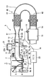
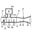
- FIG. 1 is a cross-sectional view of an exhaust passage and the like showing a configuration of an engine exhaust device according to Embodiment 1.
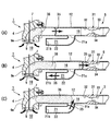
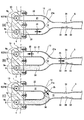
- FIG. It is a schematic diagram of a convergent-divergent nozzle. It is a figure which shows the relationship between the compression ratio of a convergent-divergent nozzle, and Mach number. It is sectional drawing of the exhaust passage etc. which show the progress of a shock wave and exhaust gas, (A) is an initial state of an exhaust stroke, (B) is a state when a shock wave propagates in a branch path, (C ) Is the state when the shock wave reflected by the branch path collides with the exhaust gas.
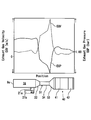
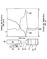
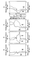
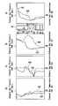
- FIG. 2 is a schematic diagram schematically showing a photograph of the inside of a convergent-divergent nozzle taken by a schlieren photographing method. It is a graph which shows the relationship between the exhaust gas flow velocity and the exhaust gas pressure in the predetermined position of a 1st exhaust pipe. It is a graph which shows the relationship between the exhaust gas flow velocity and the exhaust gas temperature in the predetermined position of a 1st exhaust pipe. It is a PV diagram showing pumping loss, (A) is that of a conventional engine, and (B) is that of the engine of the present invention.
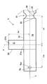
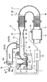
- FIG. 6 is a cross-sectional view of an exhaust passage and the like showing a configuration of an exhaust device for an engine according to a second embodiment. It is sectional drawing, such as an exhaust passage which shows the structure of the exhaust apparatus of the engine of Embodiment 3. It is the figure which showed the relationship between the exhaust gas flow velocity and exhaust gas pressure in an exhaust passage in time series.
- FIG. 5 is a cross-sectional view of an exhaust passage or the like showing the progression of shock waves and exhaust gas, similar to FIG. 4, which is a multi-cylinder engine to which the present invention is applied. It is sectional drawing of an exhaust passage etc. which show the modification of embodiment.
- the inventor of the present application has applied the principle of a convergent-divergent nozzle and can greatly reduce the pressure and temperature in the exhaust passage by a method not conventionally known as follows. I thought. The inventor of the present application has found that it is possible to improve the performance of the engine.
- the method is as follows. (1) The shock wave propagating ahead of the exhaust gas is branched. (2) The branched shock wave is delayed in time and collided with the exhaust gas to increase the pressure of the exhaust gas. (3) The exhaust gas whose pressure has been increased passes through the divergent portion and is accelerated to supersonic speed to generate a shock wave. (4) The pressure and temperature of the exhaust gas in the exhaust passage are greatly reduced.
- upstream and downstream mean upstream and downstream in the flow direction of exhaust gas, respectively.
- the engine 1 includes a cylinder body 3 and a cylinder head 4 provided at one end thereof.
- a combustion chamber 10 is formed inside the cylinder body 3 and the cylinder head 4.
- the engine 1 is a four-cycle gasoline internal combustion engine.
- the engine 1 is a single cylinder engine.
- the engine 1 may be an air-cooled engine or a water-cooled engine.
- the cylinder head 4 is formed with a downstream portion 6 of the intake passage and an upstream portion 7 of the exhaust passage.
- the cylinder head 4 includes an intake valve 8 that opens and closes an intake port 8a, an exhaust valve 9 that opens and closes an exhaust port 9a, a valve operating device (not shown) for driving the intake valve 8 and the exhaust valve 9, and the like. Is provided.
- one downstream portion 6 of the intake passage and one upstream portion 7 of the exhaust passage 16 are provided for each combustion chamber 10.
- a plurality of intake ports 8a, intake valves 8, exhaust ports 9a and / or exhaust valves 9 may be provided for one combustion chamber.
- An injector 2 that injects fuel is attached to the cylinder head 4. Although illustration is omitted, the cylinder head 4 is provided with a spark plug.
- the upstream portion of the intake passage (not shown) is connected upstream of the downstream portion 6 of the intake passage.
- a throttle valve is disposed inside the upstream portion.
- the throttle valve may be manually operated or electronically controlled by a motor.
- the exhaust device 5 includes a cylinder head 4, a first exhaust pipe 12 connected to the cylinder head 4, a second exhaust pipe 13 connected to the first exhaust pipe 12, and a second exhaust thereof. And a third exhaust pipe 14 connected to the pipe 13.
- the first exhaust pipe 12 is attached to the cylinder head 4 with bolts 11.
- the third exhaust pipe 14 forms an exhaust chamber 15 therein.
- the exhaust apparatus 5 forms the exhaust passage 16 connected in the inside through the exhaust chamber 15 from the upstream part 7 in the inside.
- the exhaust purification device 40 of this embodiment includes a first catalyst 41 and a second catalyst 42.
- the first catalyst 41 and the second catalyst 42 are provided in the exhaust passage 16.
- the second catalyst 42 is disposed downstream of the first catalyst 41.
- a space is provided between the first catalyst 41 and the second catalyst 42.
- a muffler (not shown) is connected downstream of the exhaust chamber 15.
- the exhaust gas flowing into the exhaust chamber 15 passes through the silencer and is discharged outside.
- the exhaust chamber 15 is provided with an oxygen concentration sensor 19 that detects the amount of oxygen in the exhaust gas.
- the ECU 20 which is a control device, controls the fuel injection amount of the injector 2, the ignition timing of the spark plug, or the like based on the rotational speed of the engine 1, the opening of the throttle valve, or the signal detected by the oxygen concentration sensor 19. To do.
- the ECU 20 controls the fuel injection amount of the injector 2 so that the air-fuel ratio of the air-fuel mixture sucked into the engine 1 becomes the stoichiometric air-fuel ratio, for example.
- a branch pipe 22 is provided upstream of the first exhaust pipe 12.
- One end of the branch pipe 22 is connected to the first exhaust pipe 12, and the other end is closed.
- the closed other end forms a reflection portion 21b that reflects a shock wave, which will be described later.
- the branch pipe 22 is integrally formed with the first exhaust pipe 12.
- the branch pipe 22 may be formed separately from the first exhaust pipe 12 and may be fixed to the first exhaust pipe 12.
- the first exhaust pipe 12 and the branch pipe 22 may be welded or fixed by a fastening member (not shown) such as a bolt or a rivet.
- the other end of the branch pipe 22 is formed to have a larger channel cross-sectional area than the one end.
- the shape of the branch pipe 22 is not limited to the shape shown in FIG.
- the channel cross-sectional area at the other end of the branch pipe 22 may be the same as the channel cross-sectional area at the one end, or may be smaller than the channel cross-sectional area at the one end.
- a branch portion 21 is formed inside the branch pipe 22. One end of the branch portion 21 is connected to the exhaust passage 16 and the other end is closed.
- the size of the flow path cross-sectional area of the inlet 21a of the branch portion 21 (that is, the portion communicating with the exhaust passage 16) is such that a shock wave propagating through the exhaust passage 16 propagates into the branch portion 21 as will be described later. It is formed in a size that can be used.
- X is the center line of the flow path cross section of the inlet 21a of the branching portion 21.
- a convergent-divergent nozzle 31 is provided between the branch portion 21 and the first catalyst 41.
- the convergent-divergent nozzle 31 is commonly referred to as a DeLaval nozzle.
- the convergent-divergent nozzle 31 accelerates the flow velocity of the exhaust gas flowing through the exhaust passage 16 from subsonic to supersonic.
- the convergent-divergent nozzle 31 is formed by a convergent portion 32, a throat portion 34, and a divergent portion 33.
- the convergent portion 32 is a portion where the flow path cross-sectional area gradually decreases as it goes downstream.
- the divergent portion 33 is a portion where the flow path cross-sectional area gradually increases toward the downstream.
- the throat portion 34 is a portion disposed between the convergent portion 32 and the divergent portion 33, and is the portion having the smallest channel cross-sectional area.
- a secondary air supply device 70 for supplying air to the exhaust passage 16 of the exhaust device 5 is provided.
- the secondary air supply device 70 is provided with an air cleaner 76 including a filter 76a, an air amount control valve 75 for controlling the air amount provided downstream thereof, a reed valve 74 provided downstream thereof, and a downstream thereof.
- a secondary air supply pipe 72 is connected between the branch pipe 22 and the convergent-divergent nozzle 31 in the first exhaust pipe 12.
- the tip of the secondary air supply pipe 72 faces the exhaust passage 16.
- the secondary air supply device 70 forms a secondary air supply passage 71 extending from the internal space of the air cleaner 76 to the exhaust passage.
- the supply portion 73 of the secondary air supply passage 71 is formed in a slit shape at the tip of the secondary air supply pipe 72. Thereby, the secondary air supply pipe 72 can supply air to a wide range including the center line Y of the flow path cross section of the exhaust passage 16.
- the upstream end of the secondary air supply pipe 72 is connected to an air cleaner 76 via a reed valve 74 and an air amount control valve 75.
- the reed valve 74 prevents exhaust gas from flowing into the upstream from the secondary air supply pipe 72.
- the reed valve 74 is configured to open when negative pressure is generated in the exhaust passage 16 and to flow air toward the supply portion 73 of the secondary air supply passage 71.
- the air amount control valve 75 is for adapting the amount of secondary air to the operating state of the engine 1.
- the air amount control valve 75 includes an actuator, a servo motor, a solenoid, or the like that uses an intake negative pressure as a power source.
- the opening degree of the air amount control valve 75 is controlled by the ECU 20.
- the ECU 20 closes the air amount control valve 75 or relatively reduces the throttle valve opening when the throttle valve opening is smaller than a predetermined angle.
- the predetermined angle is set in advance and is stored in the ECU 20. Further, the ECU 20 increases the opening degree of the air amount control valve 75 when the opening degree of the throttle valve is larger than the predetermined opening degree. Thus, the opening degree of the air amount control valve 75 increases or decreases in accordance with the opening degree of the throttle valve.
- the air amount control valve 75 is not necessarily required and can be omitted.
- FIG. 2 is a schematic diagram of a general convergent-divergent nozzle.
- the flow path cross-sectional area A1 at the upstream end of the convergent portion 32, the flow path cross-sectional area A2 of the throat portion 34, and the flow cross-sectional area A3 at the downstream end of the divergent portion 33 are A relationship of A1> A2 and A2 ⁇ A3 can be seen.
- the channel cross-sectional area A2 of the throat portion 34 is the same as the channel cross-sectional area A2 at the downstream end of the convergent portion 32 and the channel cross-sectional area at the upstream end of the divergent portion 33.
- FIG. 1 the present embodiment shown in FIG.
- the flow path cross-sectional areas of the convergent portion 32 and the divergent portion 33 change at a constant rate along the flow direction.
- the shapes of the convergent part 32 and the divergent part 33 are not limited at all. You may form in steps (Step by Step) like the nozzle employ
- the convergent-divergent nozzle 31 is formed so as to satisfy the conditions represented by the following formulas (1) and (2).
- Mach 1 that is, the speed of sound
- the exhaust gas can be accelerated to supersonic speed in the divergent portion 33.
- formula (1) indicates the relationship between the exhaust pipe shape and the Mach number in a one-dimensional flow with viscous friction
- formula (2) is a formula representing ⁇ in formula (1).
- M is the Mach number
- A is the cross-sectional area of the exhaust pipe in an arbitrary cross section
- D is the pipe equivalent diameter in the above-mentioned arbitrary cross section
- ⁇ is the specific heat ratio
- x is the distance in the flow direction
- f is the coefficient of friction.
- the total pressure P0 is increased so that P / P0 becomes smaller than the critical pressure ratio, a supersonic flow can be formed in the convergent-divergent nozzle 31.
- 4A to 4C schematically show the exhaust device 5.
- 4A to 4C the same or equivalent members as those shown in FIGS. 1 and 2 are denoted by the same reference numerals.
- the shock wave 35 propagates from the upstream portion 7 of the exhaust passage 16 to the inside of the first exhaust pipe 12, and further propagates toward the downstream at high speed.
- the exhaust gas 36 travels downstream in the exhaust passage 16 at a relatively low speed after the shock wave 35.
- the shock wave 35 traveling inside the first exhaust pipe 12 propagates through the shock wave propagating through the exhaust passage 16 and the branch part 21 when passing through the inlet 21a of the branch part 21. And the exhaust passage 16 and the branch portion 21 travel independently of each other.
- the shock wave 35 traveling through the exhaust passage 16 attenuates and disappears after passing through the convergent-divergent nozzle 31.
- the shock wave 35 traveling along the branching portion 21 is reflected by the reflecting portion 21 b of the branching portion 21, and travels back through the branching portion 21 and returns to the exhaust passage 16.
- the time when the reflected shock wave 35 returns from the branch portion 21 to the exhaust passage 16 is the same as or the time when the high-pressure exhaust gas 36 reaches the center of the inlet 21a of the branch portion 21.
- the length of the branch portion 21 is formed so as to be slower than that. Therefore, the shock wave 35 and the exhaust gas 36 collide with each other in the exhaust passage upstream of the divergent portion 33 and in the same or downstream of the branch portion 21.
- the distance from the center 9ac of the exhaust port 9a to the center line X of the flow path cross section of the inlet 21a of the branch portion 21 is Le
- the center line Y of the flow path cross section of the exhaust passage 16 and the reflecting portion 21b Let Ls be the distance between.
- the velocity of the exhaust gas 36 is Ve
- the propagation velocity of the shock wave 35 is Vs.
- a time T 1 from when the exhaust port 9a is opened until the exhaust gas 36 reaches the inlet 21a is expressed by Expression (3).
- a time T 2 from when the exhaust port 9 a is opened until the shock wave 35 is reflected by the reflecting portion 21 b and reaches the center line Y of the exhaust passage 16 is expressed by Expression (4).
- T 1 Le / Ve (3)
- T 2 (Le + 2Ls) / Vs (4)
- the reflected shock wave 35 and the exhaust gas 36 collide. That is, if Le / Ve ⁇ (Le + 2Ls) / Vs, the reflected shock wave 35 and the exhaust gas 36 collide in the exhaust passage upstream of the divergent section 33 and in the same or downstream of the branch section 21.
- the maximum speed of the exhaust gas 36 may be regarded as the speed Ve, and the average speed may be regarded as the speed Ve.
- the maximum propagation velocity of the reflected shock wave 35 may be regarded as the propagation velocity Vs
- the average propagation velocity may be regarded as the propagation velocity Vs.
- the distance from the center line X of the flow path cross section of the inlet 21a of the branch portion 21 to the upstream end of the divergent portion 33 is Ld, and the time from when the exhaust port 9a is opened until it is closed is tv. .
- a time T 3 from when the exhaust port 9 a is opened until the tail end of the exhaust gas 36 reaches the upstream end of the divergent portion 33 is expressed by Expression (5).
- a time T 4 from when the exhaust port 9 a is opened until the shock wave 35 is reflected by the reflecting portion 21 b and reaches the upstream end of the divergent portion 33 is expressed by Expression (6).
- T 3 tv + (Le + Ld) / Ve (5)
- T 4 (Le + 2Ls + Ld) / Vs (6)
- T 4 (Le + 2Ls + Ld) / Vs (6)
- the shock wave 35 is attenuated in the branch portion 21.
- the distance Ls may be smaller than the distance Le.
- the pressure of the exhaust gas 36 at the convergent portion 32 is further increased by the collision between the shock wave 35 and the exhaust gas 36. Then, the total pressure P0 upstream of the inlet of the convergent-divergent nozzle 31 becomes high, and the ratio P / P0 between the total pressure P0 upstream of the inlet and the downstream static pressure P of the throat portion is smaller than the critical pressure ratio 0.528. Become. As a result, the speed of the exhaust gas 36 reaches the speed of sound at the throat portion 34.
- FIG. 6 is a schematic view schematically showing a photograph of the inside of the convergent-divergent nozzle taken by the schlieren photographing method.
- a new shock wave is generated at the convergent-divergent nozzle 31.
- a traveling shock wave 35b for convenience.
- the traveling shock wave 35 b is accelerated when passing through the divergent portion 33 of the convergent-divergent nozzle 31.
- an expansion wave 35c traveling in the opposite direction to the traveling shock wave 35b is generated.
- the exhaust gas 36 existing between the traveling shock wave 35b and the expansion wave 35c is pressurized. And the temperature is greatly reduced.
- the exhaust gas has an atmospheric pressure or lower, that is, a negative pressure.
- FIG. 7 and 8 show the simulation results performed by the present inventors.
- FIG. 7 shows the exhaust gas velocity (Exhaust Gas Velocity) and the exhaust gas pressure (Exhaust Gas Pressure) at each point of the exhaust passage 16 immediately after the new shock wave 35b is generated by the convergent-divergent nozzle 31.
- FIG. 8 shows the exhaust gas velocity (Exhaust Gas Velocity) and the exhaust gas temperature (Exhaust Gas Temperature) at each point of the exhaust passage 16 immediately after the new shock wave 35b is generated by the convergent-divergent nozzle 31.
- the shock wave 35 b is generated in the convergent-divergent nozzle 31, the shock wave 35 b is accelerated in the divergent portion 33. Then, as shown in FIGS.
- the flow rate of the exhaust gas rapidly increases, and the pressure and temperature of the exhaust gas rapidly decrease.
- 7 and 8 show the flow velocity of the exhaust gas, and do not show the propagation speed of the shock wave.
- the throat portion 34 of the convergent-divergent nozzle 31 is set to be long.
- the timing at which the shock wave 35b is accelerated in the divergent portion 33 in other words, the pressure and temperature of the exhaust gas are set.
- the timing to lower can be set according to the engine.
- the pressure and temperature of the exhaust gas in the exhaust passage 16 can be significantly reduced as compared with the related art.
- air can be efficiently supplied to the exhaust passage 16 by the negative pressure generated in the exhaust passage 16.
- the negative pressure is significantly higher than that of a general engine that does not include the convergent-divergent nozzle 31 and the branch pipe 22. That is, the pressure is significantly reduced.
- the relatively high rotational speed region is a high-speed operation region or a high-load operation region in which the general engine cannot suck air.
- a sufficient amount of air can be supplied to the exhaust passage 16 without using a separate device such as an air pump that forcibly sends air into the exhaust passage 16.
- a separate device such as an air pump that forcibly sends air into the exhaust passage 16.
- the loss of engine output can be reduced. Even if a pump that supplies air is used, the load on the pump can be reduced, so that the loss of engine output can be reduced.
- the temperature of the exhaust gas 36 in the exhaust passage 16 can be lowered upstream of the first catalyst 41. Therefore, an excessive temperature rise of the first catalyst 41 and the second catalyst 42 can be suppressed.
- the purification efficiency decreases due to a phenomenon called sintering when the temperature is excessively high.
- occurrence of such sintering can be effectively suppressed. Therefore, even when the engine speed is high, the fuel can be burned at the stoichiometric air-fuel ratio. Therefore, the exhaust gas 36 can be efficiently purified by the first catalyst 41 and the second catalyst 42.
- the exhaust gas purification performance which is one of the performances of the engine 1
- two catalysts are arranged in series in the middle of the exhaust passage 16, but the present invention is not limited to this. There may be one catalyst or three or more catalysts. A plurality of catalysts may be arranged in parallel.
- the temperature of the air supplied to the exhaust passage is substantially equal to the temperature of the atmosphere, and is significantly lower than the temperature of the exhaust gas. Therefore, according to the present embodiment, the temperature of the exhaust gas can be further reduced by the relatively low temperature air supplied to the exhaust passage 16 in a large amount. Further, according to the present embodiment, since a large amount of air can be supplied upstream of the first catalyst 41, even when the fuel injection amount is increased so that the air-fuel ratio of the engine 1 becomes smaller than the stoichiometric air-fuel ratio, the Exhaust gas containing an amount of oxygen equivalent to the stoichiometric air-fuel ratio can be made to flow into the first catalyst 41.
- the temperature of the exhaust gas can be lowered by lowering the combustion temperature by making the air-fuel ratio of the engine 1 smaller than the stoichiometric air-fuel ratio.
- the air-fuel ratio is smaller than the stoichiometric air-fuel ratio, it becomes possible to cool members around the combustion chamber 10 (intake valve 8 and exhaust valve 9, valve seat, piston, etc.) with surplus fuel, and the engine The reliability which is one of the performances of 1 can be improved.
- an outboard engine is often used for a long time in an operating state in which the engine output is maximized.
- the air-fuel ratio at the time of engine operation is set to the stoichiometric air-fuel ratio
- the combustion temperature becomes excessively high. Therefore, there is a possibility that the temperature of the first catalyst 41 and the second catalyst 42 becomes too high as it is.
- As a method for reducing the catalyst temperature it is conceivable to lower the combustion temperature by making the combustion air-fuel ratio smaller than the stoichiometric air-fuel ratio.
- the purification efficiency of the first catalyst 41 and the second catalyst 42 decreases.
- the exhaust device 5 According to the exhaust device 5 according to the present embodiment, a large amount of air is supplied to the exhaust passage 16. Therefore, the combustion temperature can be lowered by making the combustion air-fuel ratio smaller than the stoichiometric air-fuel ratio while keeping the purification rate of the first catalyst 41 and the second catalyst 42 high. That is, in the exhaust device 5 according to the present embodiment, since exhaust gas and air flow into the first catalyst 41 and the second catalyst 42, it is assumed that the oxygen in the exhaust gas is insufficient due to the reduction of the combustion air-fuel ratio. Also, this oxygen can be supplemented by the air supplied to the exhaust passage 16. Therefore, even if the combustion air-fuel ratio is made smaller than the stoichiometric air-fuel ratio, harmful components in the exhaust gas can be sufficiently purified by the first catalyst 41 and the second catalyst 42.
- the combustion air-fuel ratio can be made smaller than the stoichiometric air-fuel ratio and the combustion temperature can be lowered while maintaining a state where clean exhaust gas is discharged. As a result, it is possible to more reliably prevent abnormal combustion such as self-ignition and knocking from occurring in the engine 1.
- each member in the combustion chamber 10 can be cooled by the heat of vaporization of the fuel by making the combustion air-fuel ratio smaller than the stoichiometric air-fuel ratio.
- the malfunction which arises when the inner surface of the combustion chamber 10 is cooled with fuel and the inside of the combustion chamber 10 becomes too high temperature, that is, damage to the piston, deterioration of the valve seat, and the like can be prevented.
- the temperature of the air supplied to the exhaust passage 16 is substantially equal to the temperature of the atmosphere, and is significantly lower than the temperature of the exhaust gas. Therefore, according to the present embodiment, the temperature of the exhaust gas can be lowered by the air having a relatively low temperature supplied in a large amount inside the exhaust passage 16. As a result, the occurrence of sintering in the first catalyst 41 and the second catalyst 42 can be more reliably prevented.
- the pumping loss of the engine 1 can be reduced by significantly reducing the pressure of the exhaust gas.
- the pressure of the exhaust gas in the exhaust passage 16 is significantly reduced, the piston (not shown) of the engine 1 is pulled toward the exhaust passage 16 side, that is, the top dead center side, and the work for driving the piston in the exhaust stroke is reduced. It is. This will be described with reference to FIG.
- FIG. 9 (A) is a PV diagram of a conventional engine.
- FIG. 9B is a PV diagram of the engine 1 of the present embodiment. As shown in FIG. 9 (B), when the pressure of the exhaust gas is significantly reduced, the piston is pulled by the exhaust gas even if the crankshaft (not shown) does not drive the piston, so that positive work is performed in the exhaust stroke. Is also possible. The area surrounded by the alternate long and short dash line is positive work.
- the supply portion 73 of the secondary air supply passage 71 is located upstream of the upstream end of the divergent portion 33. Therefore, the secondary air supply device 70 does not disturb the traveling shock wave 35b.
- the supply unit 73 of the secondary air supply passage 71 is located downstream of the branching unit 21. Therefore, the secondary air supply device 70 does not disturb the shock wave 35.
- the supply part 73 of the secondary air supply passage 71 may be located at substantially the same position as the branch part 21. Alternatively, the supply part 73 of the secondary air supply passage 71 may be located upstream of the branch part 21. Thereby, it can suppress that the expansion wave 35c attenuate
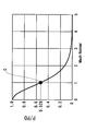
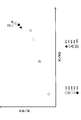
- FIG. 10 is a graph obtained from a simulation showing the relationship between the three parameters.
- the vertical axis of the graph in FIG. 10 indicates a value obtained by dividing the air-fuel ratio R when air is supplied from the secondary air supply device 70 by the air-fuel ratio R0 when air is not supplied. As the amount of air supplied increases, the value of R / R0 increases. Therefore, the vertical axis represents the amount of air supply.
- the horizontal axis divides the pressure K of the convergent section 32 when the branch pipe 22 is provided by the pressure K0 of the convergent section 32 when the secondary air supply device 70 and the branch pipe 22 are not provided. Represents a value.
- the horizontal axis represents how the pressure in the convergent portion 32 increases due to the collision between the exhaust gas 36 and the shock wave 35. Further, an increase in the value on the horizontal axis indicates that the critical pressure ratio P / P0 is decreased and the traveling shock wave 35b is accelerated by the convergent-divergent nozzle 31.
- Another parameter is the ratio of the channel cross-sectional area of the inlet 21a of the branch part 21 to the channel cross-sectional area of the exhaust passage 16 provided with the branch part 21. Hereinafter, it is simply referred to as an area ratio.
- the critical pressure ratio P / P0 is between 0.2 and 0.8, or the Mach number is between 0.5 and 1.7
- the critical pressure ratio is proportional to the Mach number.
- the critical pressure ratio is 0.2 or less or the Mach number is 1.7 or more
- the Mach number increases rapidly with a decrease in the critical pressure ratio.
- the region of the critical pressure ratio in which the Mach number rapidly increases with respect to the decrease in the critical pressure ratio is considered to correspond to the region in which the area shown in FIG. 10 is 50% or more. That is, it is considered that a shock wave having a Mach number of 1.7 or more is generated in the convergent-divergent nozzle 31 by providing the secondary air supply passage 71 having the area ratio of 50% or more.
- the area ratio may be 100%. That is, the flow passage cross-sectional area of the exhaust passage 16 provided with the branch portion 21 and the flow passage cross-sectional area of the inlet 21a of the branch portion 21 may be equal to each other. Furthermore, the area ratio may be larger than 100%. That is, the flow passage cross-sectional area of the inlet 21a of the branch portion 21 may be larger than the flow passage cross-sectional area of the exhaust passage 16 provided with the branch portion 21.
- the inlet 21a of the branch portion 21 may be an elliptical shape having a larger cross-sectional area than the exhaust passage 16 provided with the branch portion 21.
- the second embodiment uses the branch pipe 22 as a part of the secondary air supply pipe. Except for the difference in configuration, the configuration is the same as that of the first embodiment. Therefore, the detailed description of the second embodiment is substituted by FIGS. 1 to 10 of the first embodiment and the detailed description thereof.
- a reed valve 74 is attached to the secondary air supply pipe 72 that also serves as the branch pipe 22.
- the reed valve 74 constitutes the closed end of the branch pipe 22 that also serves as the secondary air supply pipe 72.
- the reed valve 74 that is a part of the secondary air supply device 70 constitutes the reflection portion 21 b of the branch portion 21 of the exhaust device 5.
- the inlet 21 a of the branch portion 21 of the exhaust device 5 constitutes the supply portion 73 of the secondary air supply device 70.
- the branch portion 21 of the exhaust device 5 constitutes a part of the secondary air supply passage 71 of the secondary air supply device 70.
- the branch pipe 22 also serves as the secondary air supply pipe 72.
- the same secondary air supply pipe 72 as described in the first embodiment is inserted into the intermediate portion of the branch pipe 22 from the outside. May be.
- the reed valve 74 is closed when the exhaust port 9a is opened, and a shock wave can be reflected by the reed valve 74.
- the reed valve 74 is opened, and air can be supplied to the exhaust passage 16 through the branch portion 21. Also in the present embodiment, a sufficient amount of air can be supplied to the exhaust passage 16.
- the present embodiment it is not necessary to form a passage that exclusively functions as the branching portion 21. Therefore, the cost can be reduced as compared with the exhaust device 5 using the dedicated branch portion 21, for example, the exhaust device 5 of the first embodiment. In addition, the degree of freedom in layout can be improved.
- the third embodiment uses the branch pipe 22 as a part of a convergent-divergent nozzle. Except for the difference in configuration, the configuration is the same as that of the first embodiment. Therefore, the detailed description of the third embodiment is substituted with FIGS. 1 to 10 of the first embodiment and the detailed description thereof.
- the convergent portion 32, the throat portion 34, and the divergent portion 33 are formed in the exhaust passage 16 downstream from the branch portion 21.
- the present inventor has come up with a structure that achieves the same effect with a simpler structure.
- the branching portion 21 which reflects the shock wave 35 and propagates again to the exhaust passage 16 is provided.
- the branch portion 21 is viewed from a different viewpoint, the flow passage cross-sectional area of the exhaust passage 16 is increased at the position of the branch portion 21. And downstream from that position, the flow path cross-sectional area becomes smaller. In other words, the convergent portion 32 and the throat portion 34 are formed in the exhaust passage by the branch portion 21.
- the flow passage cross-sectional area A5 in the upstream portion from the inlet 21a of the branch portion 21 of the exhaust passage 16 and the flow passage cross-sectional area A7 in the downstream portion from the inlet 21a of the branch portion 21 in the exhaust passage 16 are substantially the same.
- the flow path cross-sectional area obtained by adding the flow path cross-sectional area A5 of the portion of the exhaust passage 16 located upstream of the inlet 21a of the branch part 21 and the flow path cross-sectional area A4 of the branch part 21. Is larger than the flow passage cross-sectional area A7 of the portion of the exhaust passage 16 located downstream of the inlet 21a.
- the convergent portion 32 and the throat portion 34 are formed downstream of the inlet 21a. Therefore, the convergent-divergent nozzle 31 can be substantially formed simply by providing the divergent portion 33 downstream of the inlet 21a.
- A6 represents the channel cross-sectional area of the divergent portion 33, and A7 ⁇ A6.
- a portion between the inlet 21 a and the divergent portion 33 is a throat portion 34.
- the throat part 34 may be long along the flow path direction.
- the convergent part 32 and the divergent part 33 are not limited to those in which the channel cross-sectional area changes smoothly toward the downstream, but may be ones in which the channel cross-sectional area changes stepwise (Step by Step). .
- the engine 1 supplies air to the exhaust passage 16 as follows. Fuel is combusted in the combustion chamber 10. By opening the exhaust valve 9 that opens and closes the exhaust port 9 a of the combustion chamber 10, the exhaust gas 36 is discharged from the combustion chamber 10 to the exhaust passage 16. Further, a shock wave 35 that propagates through the exhaust passage 16 at a higher speed than the exhaust gas 36 is generated. At least a part of the shock wave 35 is branched from the exhaust passage 16, and the branched shock wave 35 is propagated again to the exhaust passage 16 to cause the shock wave 35 to collide with the exhaust gas, thereby increasing the pressure of the exhaust gas. Further, the pressure of the exhaust gas 36 is increased by reducing the cross-sectional area of the exhaust passage 16.
- the exhaust gas pressure is increased by causing the exhaust gas to flow through a portion of the exhaust passage 16 that has a smaller cross-sectional area as it goes downstream.
- the flow passage cross-sectional area of the exhaust passage 16 is increased to increase the flow rate of the exhaust gas 36. That is, the exhaust gas is circulated through a portion of the exhaust passage 16 where the cross-sectional area of the flow path increases toward the downstream side, thereby increasing the flow rate of the exhaust gas.
- a new shock wave 35b propagating downstream in the exhaust passage 16 is generated, and the temperature of the exhaust gas 36 is greatly reduced.
- the exhaust gas is purified through the catalyst. Therefore, it is possible to improve the exhaust gas purification efficiency by reducing the deterioration of the catalyst.
- FIG. 13 is a diagram showing the relationship between the exhaust gas flow velocity and the exhaust gas pressure in the exhaust passage 16 in time series (in Time Sequence).
- FIG. 14 is a diagram showing the relationship between the exhaust gas pressure and the exhaust gas temperature in the exhaust passage 16 in chronological order (in Time Sequence).
- the waveform shown in FIG. 7 represents the relationship between the exhaust gas flow velocity and the exhaust gas pressure during acceleration of the shock wave shown in FIG.
- FIGS. 13A and 14A show a state immediately after the exhaust port is opened.
- FIG. 13B and FIG. 14B show a state immediately after the exhaust gas collides with the shock wave downstream of the branch portion 21.
- FIG. 13C and FIG. 14C show the time when the shock wave is accelerated by the divergent portion 33.
- FIG. 13D and FIG. 14D show after the shock wave has been accelerated.
- FIG. 13A shows the exhaust gas flow velocity and the exhaust gas pressure immediately after opening the exhaust port 9a. As shown in FIG. 13A, when the exhaust port 9a is opened, the pressure of the exhaust gas near the exhaust port 9a becomes higher than the atmospheric pressure.
- FIG. 14A shows the exhaust gas pressure and the exhaust gas temperature immediately after opening the exhaust port 9a. As shown in FIG. 14 (A), the temperature of the exhaust gas 36 becomes extremely high due to the combustion heat.
- the branch portion 21 branches at least a part of the shock wave 35 propagating through the exhaust passage 16 from the exhaust passage 16.
- the reflection part 21 b of the branch part 21 reflects the branched shock wave 35.
- the reflected shock wave 35 propagates through the branch portion 21 and propagates again to the exhaust passage 16.
- the reflected shock wave 35 collides with the exhaust gas 36 flowing through the exhaust passage 16, and the pressure of the exhaust gas increases. Further, the flow passage cross-sectional area of the exhaust passage 16 is reduced at the convergent portion 32, thereby increasing the pressure of exhaust gas. Note that either the increase in the exhaust gas pressure due to the collision between the shock wave 35 and the exhaust gas 36 or the increase in the exhaust gas pressure due to the reduction in the cross-sectional area of the flow path may be first.
- FIG. 13B shows the exhaust gas flow velocity and the exhaust gas pressure immediately after the exhaust gas pressure is increased.
- the exhaust gas pressure is higher in the vicinity of the convergent portion 32 than at the time of FIG. 13 (A).
- the exhaust gas speed is higher than the time point of FIG.
- FIG. 14B shows the exhaust gas pressure and the exhaust gas temperature immediately after the exhaust gas pressure is increased.
- the exhaust gas temperature is lower than that in FIG. 14 (A) in the vicinity of the exhaust port 9a, but is higher in the upstream of the convergent portion 32.
- FIG. 13C shows the exhaust gas flow velocity and the exhaust gas pressure when the shock wave 35 b is accelerated by the divergent portion 33.
- the exhaust gas pressure drops more rapidly than the time of FIG. 13B upstream of the divergent portion 33, and the exhaust gas pressure becomes negative.
- the exhaust gas flow velocity upstream of the divergent section 33 increases rapidly.
- FIG. 14C shows the exhaust gas pressure and the exhaust gas temperature when the shock wave 35 b is accelerated by the divergent portion 33.
- the exhaust gas temperature decreases more rapidly than the time of FIG. 14B as the exhaust gas pressure upstream of the divergent section 33 decreases.
- FIG. 13 (D) shows the exhaust gas flow velocity and exhaust gas pressure after the shock wave 35b is accelerated.
- the influence of the exhaust gas pressure that has decreased upstream of the divergent portion 33 at the time of FIG. 13C reaches the exhaust port 9 a upstream of the convergent portion 32. For this reason, the exhaust gas pressure becomes negative even near the exhaust port 9a.
- FIG. 14D shows the exhaust gas pressure and the exhaust gas temperature after the shock wave 35b is accelerated. As shown in FIG. 14D, since the exhaust gas pressure becomes negative even near the exhaust port 9a, the exhaust gas temperature near the exhaust port can be significantly reduced.
- the first catalyst 41 and the second catalyst 42 are provided downstream of the divergent section 33.
- the temperature change of the exhaust gas downstream of the divergent portion 33 can be suppressed, the temperature of the exhaust gas passing through the first catalyst 41 and the second catalyst 42 is prevented from becoming too high. Can do. Thereby, even if the engine 1 is operated in a high load / high rotation region, sintering of the catalyst can be prevented.
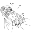
- FIG. 15 shows a ship equipped with the engine of the present invention. Specifically, it is a ship 100 in which two outboard motors 101 having the engine 1 of the present invention are mounted on a hull.
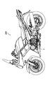
- FIG. 16 shows a vehicle equipped with the engine of the present invention. Specifically, it is a motorcycle 200 in which the engine 1 of the present invention is arranged in the center of the vehicle body.
- the application object of the engine which concerns on this invention is not limited at all.
- FIG. 17 shows a multi-cylinder engine in which exhaust ports 9a of a plurality of combustion chambers 10 are gathered by an exhaust passage, and a convergent-divergent nozzle 31 is provided downstream of the gathered portion.
- the exhaust passage connected to one exhaust port 9 a functions as the branch portion 21.
- the detailed description of FIG. 17 is the same as the detailed description of FIG. Therefore, it can be easily understood that the present invention can be applied to a multi-cylinder engine as shown in FIG.
- one exhaust port is provided for one combustion chamber, but a plurality of exhaust ports may be provided. Further, although one convergent-divergent nozzle is provided for one combustion chamber, two or more nozzles may be provided. Furthermore, it goes without saying that they can be applied to a multi-cylinder engine having a plurality of combustion chambers. The present invention can be applied to a wide variety of engines.
- one branch portion is provided for one exhaust passage, but a plurality of branch portions may be provided. Further, a branch portion having an annular passage may be provided by connecting ends of a plurality of branch portions branching from the same position of the exhaust passage 16. In that case, the shock wave propagating through each branching part collides and is reflected at the connected part. The connected part becomes the reflection part. The reflection portion is established even if a member such as a wall does not necessarily exist.
- FIG. 18 is a cross-sectional view of an exhaust passage and the like showing a modification of the embodiment.
- the secondary air supply pipe 72 that is, the supply part 73 of the secondary air supply passage 71 is provided downstream from the branch part 21.
- the secondary air supply pipe 72 that is, the supply part 73 of the secondary air supply passage 71 may be provided upstream of the branch part 21 (see reference numeral 72 b), or the same position as the branch part 21. (See reference numeral 72a).
- the exhaust device 5 includes an exhaust passage between which the flow passage cross-sectional area does not decrease between the downstream end of the divergent section 33 and the upstream end of the catalyst 41 of the exhaust purification device 40. Therefore, since the exhaust gas is not compressed, an increase in the temperature of the exhaust gas can be suppressed.
- the exhaust purification device 40 includes a catalyst 41 having a flow path cross-sectional area at the upstream end equal to or larger than a flow path cross-sectional area at the downstream end of the divergent portion 33.
- the flow path cross-sectional area of the catalyst 41 is a portion excluding the carrier of the catalyst 41, in other words, an effective opening cross-sectional area through which the exhaust gas of the catalyst main body can pass.
- the exhaust purification device 40 includes a catalyst 41 having a flow path cross-sectional area at the upstream end equal to or larger than a flow path cross-sectional area at the downstream end of the divergent section 33. Between the downstream end of the portion 33 and the upstream end of the catalyst 41, an exhaust passage 16 whose flow path cross-sectional area does not change or increases is included. Thereby, the enlargement of the exhaust device 5 and the exhaust purification device 40 can be suppressed, and a catalyst having a large flow path cross-sectional area can be provided, and the purification efficiency can be increased. In addition, since the exhaust gas is not compressed, an increase in the temperature of the exhaust gas can be suppressed.
Landscapes
- Engineering & Computer Science (AREA)
- Chemical & Material Sciences (AREA)
- Combustion & Propulsion (AREA)
- Mechanical Engineering (AREA)
- General Engineering & Computer Science (AREA)
- Chemical Kinetics & Catalysis (AREA)
- Health & Medical Sciences (AREA)
- Toxicology (AREA)
- Exhaust Gas After Treatment (AREA)
- Exhaust Silencers (AREA)
- Characterised By The Charging Evacuation (AREA)
- Cooling, Air Intake And Gas Exhaust, And Fuel Tank Arrangements In Propulsion Units (AREA)
Abstract
Description
以下、本発明の実施の形態のエンジンについて、図を用いて詳細に説明する。なお、以下の説明において、「上流」、「下流」は、排ガスの流れ方向に関する上流、下流をそれぞれ意味する。


T1=Le/Ve・・・・・・・・・・・(3)
T2=(Le+2Ls)/Vs・・・・・(4)
ここで、T1≦T2であれば、反射された衝撃波35と排ガス36とが衝突する。すなわち、Le/Ve≦(Le+2Ls)/Vsであれば、ダイバージェント部33より上流、且つ、分岐部21と同じまたは下流の排気通路で、反射された衝撃波35と排ガス36とが衝突する。なお、便宜上、例えば排ガス36の最大速度を上記速度Veと見なしてもよく、平均速度を上記速度Veと見なしてもよい。同様に、例えば反射された衝撃波35の最大伝播速度を上記伝播速度Vsと見なしてもよく、平均伝播速度を上記伝播速度Vsと見なしてもよい。
T3=tv+(Le+Ld)/Ve・・・・・(5)
T4=(Le+2Ls+Ld)/Vs・・・・(6)
ここで、T4≦T3であれば、排ガス36の全部がスロート部34を通り過ぎる前に、反射された衝撃波35と排ガス36とを衝突させることができる。すなわち、(Le+2Ls+Ld)/Vs≦tv+(Le+Ld)/Veであれば、排ガス36の全部がスロート部34を通り過ぎる前に、反射された衝撃波35と排ガス36とを衝突させることができる。
図11に示すように、実施形態2は、分岐管22を二次空気供給管の一部として利用するものである。その構成の違い以外は、全て実施形態1と同一である。従って、実施形態2の詳細説明は、実施形態1の図1~図10およびその詳細説明で代用する。分岐管22を兼ねる二次空気供給管72にリード弁74が取付けられている。リード弁74は、二次空気供給管72を兼ねる分岐管22の閉塞端を構成している。言い換えれば、二次空気供給装置70の一部であるリード弁74が、排気装置5の分岐部21の反射部21bを構成しているということである。本実施形態では、排気装置5の分岐部21の入口21aが、二次空気供給装置70の供給部73を構成していることになる。また、排気装置5の分岐部21が、二次空気供給装置70の二次空気供給通路71の一部を構成しているということでもある。なお、実施形態2では、分岐管22が二次空気供給管72を兼ねているが、実施形態1に記載した二次空気供給管72と同じものを、分岐管22の中間部分に外側から挿入してもよい。
図12に示すように、実施形態3は、分岐管22をコンバージェント-ダイバージェントノズルの一部として利用するものである。その構成の違い以外は、全て実施形態1と同一である。従って、実施形態3の詳細説明は、実施形態1の図1~図10およびその詳細説明で代用する。実施形態1および実施形態2では、コンバージェント部32とスロート部34とダイバージェント部33を、分岐部21より下流の排気通路16に形成していた。しかし、本願発明者は、鋭意研究を続けた結果、より簡単な構造で、同じ効果を得る構造を考えついた。本発明では、新たな衝撃波である進行衝撃波35bを発生させるために、衝撃波35を反射させて再び排気通路16へ伝播する分岐部21が設けられている。この分岐部21を異なる視点で捉えてみると、排気通路16は、分岐部21の位置で、その流路断面積が大きくなる。そして、その位置より下流では、流路断面積が小さくなる。言い換えると、分岐部21によって、排気通路には、コンバージェント部32とスロート部34が形成されていることになる。ここで、排気通路16の分岐部21の入口21aより上流部分の流路断面積A5と排気通路16の分岐部21の入口21aより下流部分の流路断面積A7が略同一である場合、次のような関係が成り立つ。図12に示すように、分岐部21の入口21aよりも上流に位置する排気通路16の部分の流路断面積A5と、分岐部21の流路断面積A4とを足し合わせた流路断面積は、入口21aよりも下流に位置する排気通路16の部分の流路断面積A7よりも大きい。A4+A5>A7である。したがって、入口21aの下流に、コンバージェント部32とスロート部34が形成されていると見なすことができる。よって、入口21aの下流にダイバージェント部33を設けるだけで、実質的にコンバージェント-ダイバージェントノズル31を形成することができる。A6はダイバージェント部33の流路断面積を表しており、A7<A6である。なお、入口21aとダイバージェント部33との間の部分がスロート部34となる。このように、スロート部34は流路方向に沿って長くてもよい。コンバージェント部32およびダイバージェント部33は、下流に向かって流路断面積が滑らかに変化するものに限らず、流路断面積が段階的(Step by Step)に変化するものであってもよい。
図15は、本発明のエンジンを搭載した船舶である。具体的には、本発明のエンジン1を有する船外機101を船体に2機搭載した船舶100である。図16は、本発明のエンジンを搭載した車両である。具体的には、本発明のエンジン1を車体の中央に配置した自動二輪車200である。なお、本発明に係るエンジンの適用対象は何ら限定されない。
5 排気装置
9 排気弁
9a 排気口
10 燃焼室
16 排気通路
21 分岐部
21a 入口
21b 反射部
31 コンバージェント-ダイバージェントノズル
32 コンバージェント部
33 ダイバージェント部
34 スロート部
35 衝撃波
35b 進行衝撃波
35c 膨張波
36 排ガス
71 二次空気供給通路
Claims (15)
- 排気口が形成された燃焼室と、
前記排気口を開閉する排気弁と、
前記燃焼室から前記排気口を通じて排出される排ガスを導く排気通路を有する排気装置と、
前記排気通路に設けられた触媒を有する排気浄化装置と、を備え、
前記排気装置は、
上流端の流路断面積より下流端の流路断面積が小さいコンバージェント部と、
そのコンバージェント部より下流に設けられ、且つ、上流端の流路断面積より下流端の流路断面積が大きいダイバージェント部と、
前記排気口が開かれた時に前記燃焼室から前記排気通路に流れ込む排ガスよりも高速で前記排気通路を下流に向かって伝播する衝撃波を、前記ダイバージェント部より上流の排気通路から分岐し、且つ、その衝撃波を再び前記排気通路へ伝播する分岐部と、を含み、
前記燃焼室から前記排気通路に流れ込む排ガスを、前記コンバージェント部を通過させ、且つ、前記分岐部と前記ダイバージェント部との間で前記分岐部を伝播した衝撃波と衝突させることにより、前記コンバージェント部でのその排ガスの圧力を高め、
その排ガスを、前記ダイバージェント部を通過させて新たな衝撃波を発生させ、その排ガスの温度を低下させ、
前記排気浄化装置の前記触媒は、前記ダイバージェント部より下流の前記排気通路に設けられている、エンジン。 - 排気口が形成された燃焼室と、
前記排気口を開閉する排気弁と、
前記燃焼室から前記排気口を通じて排出される排ガスを導く排気通路を有する排気装置と、
前記排気通路に設けられた触媒を有する排気浄化装置と、を備え、
前記排気装置は、
上流端の流路断面積より下流端の流路断面積が小さいコンバージェント部と、
そのコンバージェント部より下流に設けられ、且つ、上流端の流路断面積より下流端の流路断面積が大きいダイバージェント部と、
前記排気口が開かれた時に前記燃焼室から前記排気通路に流れ込む排ガスよりも高速で前記排気通路を下流に向かって伝播する衝撃波を、前記ダイバージェント部より上流の排気通路から分岐し、且つ、その衝撃波を再び前記排気通路へ伝播する分岐部と、を含み、
前記排気浄化装置の前記触媒は、前記ダイバージェント部より下流の前記排気通路に設けられ、
前記排気口を開いたときに前記燃焼室から排出される排ガスの流速をVe、前記排気通路を伝播する衝撃波の伝播速度をVsとしたときに、前記排気口と前記分岐部の入口との間の距離Le、前記分岐部の前記衝撃波の伝播する距離Lsが、
Le/Ve≦(Le+2Ls)/Vs
の関係を満たし、且つ、
前記排気口が開いてから閉じるまでの時間をtvとしたときに、前記分岐部の入口と前記ダイバージェント部との間の距離Ldが、
(Le+2Ls+Ld)/Vs≦tv+(Le+Ld)/Ve
の関係を満たす、エンジン。 - 前記排気装置は、前記ダイバージェント部の下流端と前記触媒の上流端の間で、その流路断面積が減少しない排気通路を含む、請求項1または2に記載のエンジン。
- 前記排気浄化装置は、その上流端の流路断面積が前記ダイバージェント部の下流端の流路断面積と同じか、それより大きい前記触媒を含む、請求項1または2に記載のエンジン。
- 前記排気浄化装置は、その上流端の流路断面積が前記ダイバージェント部の下流端の流路断面積と同じか、それより大きい前記触媒を含み、
前記排気装置は、前記ダイバージェント部の下流端と前記触媒の上流端の間で、その流路断面積が変わらないまたは増加する前記排気通路を含む、請求項1または2に記載のエンジン。 - 請求項1または2に記載のエンジンを備えた車両。
- 請求項3に記載のエンジンを備えた車両。
- 請求項4に記載のエンジンを備えた車両。
- 請求項5に記載のエンジンを備えた車両。
- 請求項1または2に記載のエンジンを備えた船舶。
- 請求項3に記載のエンジンを備えた船舶。
- 請求項4に記載のエンジンを備えた船舶。
- 請求項5に記載のエンジンを備えた船舶。
- 燃焼室内で燃料を燃焼させる工程と、
前記燃焼室の排気口を開閉する排気弁を開くことにより、前記燃焼室から排気通路に排ガスを排出するとともに、前記排ガスよりも高速で前記排気通路を伝播する衝撃波を発生させる工程と、
前記衝撃波の少なくとも一部を前記排気通路から分岐させ、且つ、その分岐した衝撃波を再び前記排気通路へ伝播させて前記衝撃波を前記排ガスに衝突させることによって、前記排ガスの圧力を高める工程と、
前記排気通路の上流部の流路断面積より下流部の流路断面積が小さい部分に前記排ガスを流通させることによって前記排ガスの圧力を高める工程と、
前記排ガスを、前記排気通路の上流部の流路断面積より下流部の流路断面積が大きい部分に流通させることにより、前記排気通路を下流に向かって伝播する新たな衝撃波を発生させ、前記排ガスの温度を低くする工程と、
触媒を通過させて前記排ガスを浄化する工程と、
を含むエンジンの排ガス浄化方法。 - 請求項14に記載の排ガス浄化方法を採用したエンジン。
Priority Applications (8)
| Application Number | Priority Date | Filing Date | Title |
|---|---|---|---|
| BRPI0903708-0A BRPI0903708A2 (pt) | 2008-06-13 | 2009-06-15 | Motor de combustão interna, veículo, embarcação marítima, e método de purificação de gás de descarga para motor de combustão interna |
| EP09756229.2A EP2299072B1 (en) | 2008-06-13 | 2009-06-15 | Engine, vehicle, boat, and engine exhaust gas cleaning method |
| CN2009800004599A CN101688462B (zh) | 2008-06-13 | 2009-06-15 | 内燃机、车辆、船舶以及用于内燃机的排气清洁方法 |
| JP2010516904A JP5214729B2 (ja) | 2008-06-13 | 2009-06-15 | エンジン、車両、および船舶 |
| ES09756229T ES2421384T3 (es) | 2008-06-13 | 2009-06-15 | Motor, vehículo, embarcación y método de depuración de gases de escape de motor |
| TW098120021A TWI372815B (en) | 2008-06-13 | 2009-06-15 | Internal combustion engine, vehicle, marine vessel, and exhaust gas cleaning method for internal combustion engine |
| US12/669,810 US8316639B2 (en) | 2008-06-13 | 2009-06-15 | Internal combustion engine, vehicle, marine vessel, and exhaust gas cleaning method for internal combustion engine |
| AP2009005081A AP2370A (en) | 2008-06-13 | 2009-06-15 | Internal combustion engine, vehicle, marine vessel, and exhaust gas cleaning method for internal combustion engine. |
Applications Claiming Priority (4)
| Application Number | Priority Date | Filing Date | Title |
|---|---|---|---|
| JP2008155070 | 2008-06-13 | ||
| JP2008-155070 | 2008-06-13 | ||
| JP2008-188428 | 2008-07-22 | ||
| JP2008188428 | 2008-07-22 |
Publications (1)
| Publication Number | Publication Date |
|---|---|
| WO2009151137A1 true WO2009151137A1 (ja) | 2009-12-17 |
Family
ID=41416837
Family Applications (3)
| Application Number | Title | Priority Date | Filing Date |
|---|---|---|---|
| PCT/JP2009/060854 Ceased WO2009151136A1 (ja) | 2008-06-13 | 2009-06-15 | エンジン、車両、船舶、およびエンジンの二次空気供給方法 |
| PCT/JP2009/060856 Ceased WO2009151138A1 (ja) | 2008-06-13 | 2009-06-15 | 多気筒エンジン、車両、船舶、および多気筒エンジンの排気方法 |
| PCT/JP2009/060855 Ceased WO2009151137A1 (ja) | 2008-06-13 | 2009-06-15 | エンジン、車両、船舶、およびエンジンの排ガス浄化方法 |
Family Applications Before (2)
| Application Number | Title | Priority Date | Filing Date |
|---|---|---|---|
| PCT/JP2009/060854 Ceased WO2009151136A1 (ja) | 2008-06-13 | 2009-06-15 | エンジン、車両、船舶、およびエンジンの二次空気供給方法 |
| PCT/JP2009/060856 Ceased WO2009151138A1 (ja) | 2008-06-13 | 2009-06-15 | 多気筒エンジン、車両、船舶、および多気筒エンジンの排気方法 |
Country Status (12)
| Country | Link |
|---|---|
| US (3) | US8316639B2 (ja) |
| EP (3) | EP2299072B1 (ja) |
| JP (3) | JP5214728B2 (ja) |
| CN (3) | CN101688462B (ja) |
| AP (2) | AP2370A (ja) |
| BR (3) | BRPI0903893A2 (ja) |
| CO (3) | CO6251339A2 (ja) |
| ES (3) | ES2421214T3 (ja) |
| MY (3) | MY150163A (ja) |
| RU (2) | RU2436970C2 (ja) |
| TW (3) | TWI372815B (ja) |
| WO (3) | WO2009151136A1 (ja) |
Cited By (2)
| Publication number | Priority date | Publication date | Assignee | Title |
|---|---|---|---|---|
| JP7197099B1 (ja) | 2022-08-31 | 2022-12-27 | 勝美 柴田 | 分離装置 |
| JP2023170842A (ja) * | 2022-05-20 | 2023-12-01 | 株式会社Subaru | 車両 |
Families Citing this family (25)
| Publication number | Priority date | Publication date | Assignee | Title |
|---|---|---|---|---|
| DE102010051691A1 (de) * | 2010-11-17 | 2012-05-24 | Bayerische Motoren Werke Aktiengesellschaft | Abgasanlage |
| US20120318602A1 (en) * | 2011-06-20 | 2012-12-20 | Caterpillar Inc. | Exhaust System for Machine |
| KR101521398B1 (ko) * | 2011-08-05 | 2015-05-18 | 에미텍 게젤샤프트 퓌어 에미시온스테크놀로기 엠베하 | 액상의 환원제 공급 장치 |
| JP5845777B2 (ja) * | 2011-09-28 | 2016-01-20 | マツダ株式会社 | 多気筒エンジンの吸排気装置 |
| US8757129B1 (en) | 2013-07-24 | 2014-06-24 | Thrival Tech, LLC | Multi-fuel plasma injector |
| US9387438B2 (en) | 2014-02-14 | 2016-07-12 | Tenneco Automotive Operating Company Inc. | Modular system for reduction of sulphur oxides in exhaust |
| FR3024679B1 (fr) * | 2014-08-07 | 2017-11-03 | Manitou Bf | Chariot de manutention ou d'elevation de personnel |
| FR3026433B1 (fr) * | 2014-09-26 | 2016-12-09 | Renault Sa | Volume acoustique pour une ligne d'echappement d'un vehicule automobile |
| JP6102963B2 (ja) * | 2015-03-12 | 2017-03-29 | マツダ株式会社 | エンジンの制御装置 |
| US9447754B1 (en) | 2015-07-02 | 2016-09-20 | Bright Acceleration Technologies LLC | Method and apparatus for internal combustion engine system with improved turbocharging |
| EP3411571B1 (en) * | 2016-02-05 | 2021-10-27 | Cummins, Inc. | System for equalizing backpressure in engine cylinders |
| SI3488087T1 (sl) * | 2016-07-25 | 2022-01-31 | BORLA, David, Akiba | Zvočno skaliran izpušni sistem |
| US9638095B1 (en) | 2016-09-01 | 2017-05-02 | Bright Acceleration Technologies LLC | Synergistic induction and turbocharging in internal combustion engine systems |
| US10697357B2 (en) | 2016-09-01 | 2020-06-30 | Bright Acceleration Technologies LLC | Cross-port air flow to reduce pumping losses |
| US10364739B2 (en) | 2016-09-01 | 2019-07-30 | Bright Acceleration Technologies LLC | Synergistic induction and turbocharging in internal combustion engine systems |
| US10107215B2 (en) | 2016-09-01 | 2018-10-23 | Bright Acceleration Technologies LLC | Synergistic induction and turbocharging in internal combustion engine systems |
| US10132222B2 (en) * | 2016-12-05 | 2018-11-20 | Caterpillar Inc. | Exhaust aftertreatment system, apparatus, and method |
| WO2019059942A1 (en) * | 2017-09-25 | 2019-03-28 | Faurecia Emissions Control Technologies, Usa, Llc | ACOUSTIC VOLUME AT THE HEATING EXHAUST END OF EXHAUST SYSTEMS |
| US10941693B2 (en) | 2018-01-18 | 2021-03-09 | Faurecia Emissions Control Technologies, Usa, Llc | Vehicle frame with acoustic volume for an exhaust system |
| DE102018214922A1 (de) * | 2018-09-03 | 2020-03-05 | Continental Automotive Gmbh | Abgasanlage |
| CN112912597B (zh) * | 2018-10-30 | 2023-05-23 | Tvs电机股份有限公司 | 内燃发动机及其制造方法 |
| CN110159407B (zh) * | 2019-05-24 | 2021-03-30 | 南通迈程汽车技术有限公司 | 一种用于汽车尾气异常排放时的处理装置 |
| DE102021102413A1 (de) * | 2021-02-03 | 2022-08-04 | Bayerische Motoren Werke Aktiengesellschaft | Kraftfahrzeug |
| US12158091B2 (en) | 2021-03-19 | 2024-12-03 | Honda Motor Co., Ltd. | V-type engine, outboard motor, and watercraft |
| IT202300002826A1 (it) * | 2023-02-20 | 2024-08-20 | Piaggio & C Spa | Motore con risuonatore sul condotto di scarico e veicolo comprendente detto motore |
Citations (4)
| Publication number | Priority date | Publication date | Assignee | Title |
|---|---|---|---|---|
| JPS61155620A (ja) * | 1984-12-21 | 1986-07-15 | アウトボ−ド・マ−リン・コ−ポレ−シヨン | エンジン装置 |
| JPS61212629A (ja) * | 1985-03-15 | 1986-09-20 | Ishikawajima Shibaura Kikai Kk | 2サイクルエンジンの排気装置 |
| JP2004150310A (ja) * | 2002-10-29 | 2004-05-27 | Honda Motor Co Ltd | 内燃機関の排気装置 |
| JP2008031868A (ja) * | 2006-07-26 | 2008-02-14 | Yamaha Marine Co Ltd | 8気筒エンジンにおける排気装置 |
Family Cites Families (50)
| Publication number | Priority date | Publication date | Assignee | Title |
|---|---|---|---|---|
| GB319426A (en) | 1928-07-03 | 1929-09-26 | Frederik Vilhelm Haugsted | Improvements in multi-cylinder internal combustion engines with exhaust manifolds |
| US2118209A (en) * | 1935-01-16 | 1938-05-24 | Bendix Prod Corp | Outboard motor assembly |
| GB522861A (en) * | 1939-01-12 | 1940-06-28 | Paul Eberspaecher | Improvements in or relating to exhaust gas systems for internal combustion engines |
| US2297046A (en) * | 1939-08-25 | 1942-09-29 | Maxim Silencer Co | Means for preventing shock excitation of acoustic conduits or chambers |
| US3116596A (en) * | 1961-05-25 | 1964-01-07 | Universal Oil Prod Co | Flywheel air pump |
| US3180077A (en) * | 1962-03-20 | 1965-04-27 | Ite Circuit Breaker Ltd | Wave machine to initiate scavenging of internal combustion |
| US3254484A (en) * | 1964-01-23 | 1966-06-07 | Kopper John Stephen | Acoustical resonance apparatus for increasing the power output of an internal combustion engine |
| US3453824A (en) * | 1967-11-20 | 1969-07-08 | Joseph M Biesecker | Exhaust system for motor bikes |
| US3491534A (en) * | 1968-04-24 | 1970-01-27 | Trans Dapt Of California Inc | Exhaust manifold |
| US3563030A (en) * | 1969-02-10 | 1971-02-16 | Tenneco Inc | Exhaust system |
| US3655011A (en) * | 1970-06-10 | 1972-04-11 | Tenneco Inc | Sound attenuating chamber |
| US3653212A (en) * | 1970-10-30 | 1972-04-04 | Gen Motors Corp | Exhaust emission control system |
| US3797241A (en) * | 1970-12-09 | 1974-03-19 | Herbert Kern | Apparatus for controlling the exhaust emissions from internal combustion engines |
| DE2525769C3 (de) * | 1975-06-10 | 1980-11-27 | Maschinenfabrik Augsburg-Nuernberg Ag, 8500 Nuernberg | Freisaugende Achtzylinder-Dieselbrennkraftmaschine |
| US4094284A (en) * | 1975-10-21 | 1978-06-13 | Eltra Corporation | Emission control system |
| JPS52131022A (en) * | 1976-04-26 | 1977-11-02 | Toyota Motor Corp | Exhaust pipe in multi-cylinder internal combustion engine |
| US4501341A (en) * | 1981-03-12 | 1985-02-26 | Jones Adrian D | Low frequency muffler |
| JPS58202320A (ja) * | 1982-05-08 | 1983-11-25 | Honda Motor Co Ltd | 2サイクルエンジン用排気装置 |
| US4690245A (en) * | 1983-03-17 | 1987-09-01 | Stemco, Inc. | Flattened venturi, method and apparatus for making |
| JPS6019911A (ja) * | 1983-07-12 | 1985-02-01 | Nippon Soken Inc | 二次空気導入管 |
| FR2577276A1 (fr) * | 1985-02-11 | 1986-08-14 | Lepretre Joel | Dispositif d'echappement des gaz brules d'un moteur thermique |
| JPS6258017A (ja) * | 1985-09-06 | 1987-03-13 | Suzuki Motor Co Ltd | 多気筒エンジンの排気装置 |
| JPH0730704B2 (ja) * | 1986-07-14 | 1995-04-10 | 三信工業株式会社 | 多気筒2サイクル内然機関 |
| US4835965A (en) * | 1987-05-21 | 1989-06-06 | Outboard Marine Corporation | "Y" equal length exhaust system for two-cycle engines |
| JPH0176520U (ja) * | 1987-11-10 | 1989-05-24 | ||
| JPH01147110A (ja) * | 1987-12-03 | 1989-06-08 | Yoshiaki Tsunoda | 吸引式空冷機構に於る負圧空気流の加速装置 |
| JP2742425B2 (ja) * | 1988-08-02 | 1998-04-22 | ヤマハ発動機株式会社 | 2サイクルエンジンの排気タイミング制御装置 |
| JP2530580B2 (ja) * | 1988-09-20 | 1996-09-04 | 義明 角田 | 内燃機関に於る強制吸気方法 |
| WO1992003639A1 (en) | 1990-08-13 | 1992-03-05 | Flowmaster, Inc. | Header assembly for internal combustion engine and method |
| RU2002077C1 (ru) * | 1991-04-17 | 1993-10-30 | Gyavgyanen Yurij V | Способ нейтрализации отработавших газов преимущественно двигател внутреннего сгорани и устройство дл его осуществлени |
| US5355973A (en) * | 1992-06-02 | 1994-10-18 | Donaldson Company, Inc. | Muffler with catalytic converter arrangement; and method |
| JP3276425B2 (ja) * | 1992-11-26 | 2002-04-22 | 因幡電機産業株式会社 | キャップ |
| US5425232A (en) | 1993-09-28 | 1995-06-20 | Outboard Marine Corporation | Marine propulsion device with means for supplying secondary air to catalytic converter |
| US5548955A (en) * | 1994-10-19 | 1996-08-27 | Briggs & Stratton Corporation | Catalytic converter having a venturi formed from two stamped components |
| ES2142144T3 (es) * | 1996-03-05 | 2000-04-01 | Swissauto Eng Sa | Motor de encendido por bujia con supercompresor de onda de presion. |
| JP3330019B2 (ja) | 1996-06-04 | 2002-09-30 | 本田技研工業株式会社 | エンジンの排気浄化装置 |
| US5768891A (en) * | 1996-09-16 | 1998-06-23 | Wagner; Dane | Exhaust system with scavenging venturi |
| JP3499736B2 (ja) * | 1997-12-19 | 2004-02-23 | 株式会社共立 | 内燃エンジンのマフラー |
| JP2000314322A (ja) * | 1999-05-06 | 2000-11-14 | Over Racing Projects:Kk | 多気筒エンジンの排気管結合構造 |
| SE9903403L (sv) | 1999-09-22 | 2001-03-23 | Electrolux Ab | Tvåtakts förbränningsmotor |
| JP2004504330A (ja) * | 2000-07-13 | 2004-02-12 | インヴィトロジェン コーポレーション | 溶解マトリクスを用いてタンパク質およびペプチドの迅速な抽出および単離のための方法および組成物 |
| GB0103522D0 (en) * | 2001-02-13 | 2001-03-28 | Ricardo Consulting Eng | Reciprocating Engines |
| DE10141431A1 (de) * | 2001-08-23 | 2003-03-20 | Fev Motorentech Gmbh | Kolbenbrennkraftmaschine mit druckentlastbaren Gasauslaßventilen |
| RU2212548C1 (ru) * | 2002-01-14 | 2003-09-20 | Алтайский государственный технический университет им. И.И. Ползунова | Устройство для очистки отработавших газов двигателя внутреннего сгорания |
| CN1372071A (zh) * | 2002-03-02 | 2002-10-02 | 干方飞 | 气压波相消的内燃机废气再循环排气消声系统 |
| CN2615343Y (zh) * | 2003-04-09 | 2004-05-12 | 中国第一汽车集团公司 | 发动机排气管 |
| CA2569447A1 (en) * | 2005-11-30 | 2007-05-30 | Nett Technologies Inc. | Device for exhaust gas purification for spark-ignited engines |
| JP4176788B2 (ja) * | 2006-06-22 | 2008-11-05 | エムエーエヌ・ディーゼル・エーエス | 大型2サイクルディーゼルエンジン用の排気ガスレシーバー |
| JP2008031925A (ja) * | 2006-07-28 | 2008-02-14 | Nissan Motor Co Ltd | 排気通路構造 |
| US20080093162A1 (en) * | 2006-10-23 | 2008-04-24 | Marocco Gregory M | Gas flow sound attenuation device |
-
2009
- 2009-06-15 WO PCT/JP2009/060854 patent/WO2009151136A1/ja not_active Ceased
- 2009-06-15 CN CN2009800004599A patent/CN101688462B/zh not_active Expired - Fee Related
- 2009-06-15 ES ES09756230T patent/ES2421214T3/es active Active
- 2009-06-15 ES ES09756232.6T patent/ES2436436T3/es active Active
- 2009-06-15 AP AP2009005081A patent/AP2370A/xx active
- 2009-06-15 EP EP09756229.2A patent/EP2299072B1/en not_active Not-in-force
- 2009-06-15 TW TW098120021A patent/TWI372815B/zh not_active IP Right Cessation
- 2009-06-15 RU RU2009146998/06A patent/RU2436970C2/ru not_active IP Right Cessation
- 2009-06-15 JP JP2010516903A patent/JP5214728B2/ja not_active Expired - Fee Related
- 2009-06-15 CN CN2009800004601A patent/CN101680348B/zh not_active Expired - Fee Related
- 2009-06-15 BR BRPI0903893-0A patent/BRPI0903893A2/pt not_active Application Discontinuation
- 2009-06-15 BR BRPI0903708-0A patent/BRPI0903708A2/pt not_active Application Discontinuation
- 2009-06-15 TW TW098120024A patent/TWI372818B/zh not_active IP Right Cessation
- 2009-06-15 AP AP2009005080A patent/AP2598A/xx active
- 2009-06-15 US US12/669,810 patent/US8316639B2/en not_active Expired - Fee Related
- 2009-06-15 MY MYPI20094915A patent/MY150163A/en unknown
- 2009-06-15 ES ES09756229T patent/ES2421384T3/es active Active
- 2009-06-15 EP EP09756230.0A patent/EP2163739B1/en not_active Not-in-force
- 2009-06-15 US US12/669,809 patent/US8359836B2/en not_active Expired - Fee Related
- 2009-06-15 BR BRPI0903707-1A patent/BRPI0903707A2/pt not_active Application Discontinuation
- 2009-06-15 MY MYPI20094914A patent/MY153186A/en unknown
- 2009-06-15 JP JP2010516904A patent/JP5214729B2/ja not_active Expired - Fee Related
- 2009-06-15 TW TW098120025A patent/TWI370200B/zh not_active IP Right Cessation
- 2009-06-15 RU RU2009147025/06A patent/RU2434148C2/ru not_active IP Right Cessation
- 2009-06-15 WO PCT/JP2009/060856 patent/WO2009151138A1/ja not_active Ceased
- 2009-06-15 CN CN200980000457XA patent/CN101680347B/zh not_active Expired - Fee Related
- 2009-06-15 US US12/669,811 patent/US8336303B2/en not_active Expired - Fee Related
- 2009-06-15 MY MYPI20094913A patent/MY153205A/en unknown
- 2009-06-15 EP EP09756232.6A patent/EP2325447B1/en not_active Not-in-force
- 2009-06-15 JP JP2010516905A patent/JP5194120B2/ja not_active Expired - Fee Related
- 2009-06-15 WO PCT/JP2009/060855 patent/WO2009151137A1/ja not_active Ceased
- 2009-12-16 CO CO09144015A patent/CO6251339A2/es active IP Right Grant
- 2009-12-16 CO CO09144019A patent/CO6251342A2/es active IP Right Grant
- 2009-12-16 CO CO09144021A patent/CO6251343A2/es not_active Application Discontinuation
Patent Citations (4)
| Publication number | Priority date | Publication date | Assignee | Title |
|---|---|---|---|---|
| JPS61155620A (ja) * | 1984-12-21 | 1986-07-15 | アウトボ−ド・マ−リン・コ−ポレ−シヨン | エンジン装置 |
| JPS61212629A (ja) * | 1985-03-15 | 1986-09-20 | Ishikawajima Shibaura Kikai Kk | 2サイクルエンジンの排気装置 |
| JP2004150310A (ja) * | 2002-10-29 | 2004-05-27 | Honda Motor Co Ltd | 内燃機関の排気装置 |
| JP2008031868A (ja) * | 2006-07-26 | 2008-02-14 | Yamaha Marine Co Ltd | 8気筒エンジンにおける排気装置 |
Non-Patent Citations (1)
| Title |
|---|
| See also references of EP2299072A4 * |
Cited By (3)
| Publication number | Priority date | Publication date | Assignee | Title |
|---|---|---|---|---|
| JP2023170842A (ja) * | 2022-05-20 | 2023-12-01 | 株式会社Subaru | 車両 |
| JP7197099B1 (ja) | 2022-08-31 | 2022-12-27 | 勝美 柴田 | 分離装置 |
| JP2024033961A (ja) * | 2022-08-31 | 2024-03-13 | 勝美 柴田 | 分離装置 |
Also Published As
Similar Documents
| Publication | Publication Date | Title |
|---|---|---|
| JP5214729B2 (ja) | エンジン、車両、および船舶 | |
| JP4880071B2 (ja) | エンジン、車両、船舶、およびエンジンの排気方法 | |
| EP2511494A1 (en) | Engine, and vehicle and ship that comprise same | |
| TWI444534B (zh) | Engine, and with its vehicles and ships | |
| JP2010019080A (ja) | 船外機用多気筒エンジンの排気装置 | |
| JP2018141456A (ja) | 往復動型4ストローク火花点火内燃機関 |
Legal Events
| Date | Code | Title | Description |
|---|---|---|---|
| WWE | Wipo information: entry into national phase |
Ref document number: 200980000459.9 Country of ref document: CN |
|
| WWE | Wipo information: entry into national phase |
Ref document number: 12009502333 Country of ref document: PH Ref document number: 2009756229 Country of ref document: EP |
|
| WWE | Wipo information: entry into national phase |
Ref document number: 4259/KOLNP/2009 Country of ref document: IN |
|
| WWE | Wipo information: entry into national phase |
Ref document number: 09144019 Country of ref document: CO |
|
| WWE | Wipo information: entry into national phase |
Ref document number: 2009147025 Country of ref document: RU |
|
| WWE | Wipo information: entry into national phase |
Ref document number: PI 20094913 Country of ref document: MY |
|
| WWE | Wipo information: entry into national phase |
Ref document number: 12669810 Country of ref document: US |
|
| 121 | Ep: the epo has been informed by wipo that ep was designated in this application |
Ref document number: 09756229 Country of ref document: EP Kind code of ref document: A1 |
|
| WWE | Wipo information: entry into national phase |
Ref document number: 2010516904 Country of ref document: JP |
|
| NENP | Non-entry into the national phase |
Ref country code: DE |
|
| ENP | Entry into the national phase |
Ref document number: PI0903708 Country of ref document: BR Kind code of ref document: A2 Effective date: 20091215 |