WO2009151203A1 - 발열체 및 이의 제조방법 - Google Patents
발열체 및 이의 제조방법 Download PDFInfo
- Publication number
- WO2009151203A1 WO2009151203A1 PCT/KR2009/001336 KR2009001336W WO2009151203A1 WO 2009151203 A1 WO2009151203 A1 WO 2009151203A1 KR 2009001336 W KR2009001336 W KR 2009001336W WO 2009151203 A1 WO2009151203 A1 WO 2009151203A1
- Authority
- WO
- WIPO (PCT)
- Prior art keywords
- heating element
- pattern
- line
- conductive heating
- transparent substrate
- Prior art date
- Legal status (The legal status is an assumption and is not a legal conclusion. Google has not performed a legal analysis and makes no representation as to the accuracy of the status listed.)
- Ceased
Links
Images




Classifications
-
- C—CHEMISTRY; METALLURGY
- C03—GLASS; MINERAL OR SLAG WOOL
- C03C—CHEMICAL COMPOSITION OF GLASSES, GLAZES OR VITREOUS ENAMELS; SURFACE TREATMENT OF GLASS; SURFACE TREATMENT OF FIBRES OR FILAMENTS MADE FROM GLASS, MINERALS OR SLAGS; JOINING GLASS TO GLASS OR OTHER MATERIALS
- C03C17/00—Surface treatment of glass, not in the form of fibres or filaments, by coating
- C03C17/34—Surface treatment of glass, not in the form of fibres or filaments, by coating with at least two coatings having different compositions
-
- B—PERFORMING OPERATIONS; TRANSPORTING
- B60—VEHICLES IN GENERAL
- B60S—SERVICING, CLEANING, REPAIRING, SUPPORTING, LIFTING, OR MANOEUVRING OF VEHICLES, NOT OTHERWISE PROVIDED FOR
- B60S1/00—Cleaning of vehicles
- B60S1/02—Cleaning windscreens, windows or optical devices
-
- H—ELECTRICITY
- H05—ELECTRIC TECHNIQUES NOT OTHERWISE PROVIDED FOR
- H05B—ELECTRIC HEATING; ELECTRIC LIGHT SOURCES NOT OTHERWISE PROVIDED FOR; CIRCUIT ARRANGEMENTS FOR ELECTRIC LIGHT SOURCES, IN GENERAL
- H05B3/00—Ohmic-resistance heating
- H05B3/84—Heating arrangements specially adapted for transparent or reflecting areas, e.g. for demisting or de-icing windows, mirrors or vehicle windshields
-
- H—ELECTRICITY
- H05—ELECTRIC TECHNIQUES NOT OTHERWISE PROVIDED FOR
- H05B—ELECTRIC HEATING; ELECTRIC LIGHT SOURCES NOT OTHERWISE PROVIDED FOR; CIRCUIT ARRANGEMENTS FOR ELECTRIC LIGHT SOURCES, IN GENERAL
- H05B2203/00—Aspects relating to Ohmic resistive heating covered by group H05B3/00
- H05B2203/017—Manufacturing methods or apparatus for heaters
Definitions
- the present invention relates to a heating element and a method of manufacturing the same. Specifically, the present invention relates to a heating element and a method for manufacturing the same, which are not conspicuous, have excellent heat generation performance at low voltage, and include a pattern capable of minimizing light diffraction and interference.
- the heating glass utilizes the concept of attaching a hot wire sheet to the glass surface or forming a hot wire directly on the glass surface and applying heat to both terminals of the hot wire to generate heat from the hot wire, thereby raising the temperature of the glass surface. It is also important that automotive or architectural pyrogenic glass has a low resistance in order to generate heat well, but it should not be distracting to human eyes.
- the conventional transparent heating glass has been proposed to manufacture a transparent conductive material such as ITO (Indium Tin Oxide) or Ag thin film by sputtering process to form a heating layer and then connecting the electrode to the front end.
- the heating glass according to this method has a problem that it is difficult to drive at a low voltage of 40V or less due to the high sheet resistance.
- the present invention is to provide a heating element and a method of manufacturing the same that is not noticeable and can minimize side effects caused by diffraction and interference in the light source after sunset and excellent heat generation performance at low voltage. The purpose.
- one embodiment of the present invention is a heating element including a transparent substrate, a conductive heating line provided on at least one surface of the transparent substrate, a bus bar electrically connected to the conductive heating line and a power supply unit connected to the bus bar. At least 30% of the total area of the transparent base material is composed of continuous closed figures, and a ratio of the standard heating to the average value of the area of the closed figures is 2% or more. It provides a heating element having a.
- Another embodiment of the present invention is a method of manufacturing a heating element comprising the step of forming a conductive heating wire on a transparent substrate, forming a bus bar electrically connected to the conductive heating wire, and forming a power source connected to the bus bar.
- the conductive heating line is formed of continuous closed figures distributed over 30% of the total area of the transparent base material, and the ratio (area distribution ratio) of the standard deviation to the average value of the areas of the closed figures is 2%.
- Provided is a method of manufacturing a heating element, which is formed in the above pattern.
- the conductive heating line may be formed by a printing method, a photolithography method, a photography method, a method using a mask, a sputtering method, or an inkjet method.
- the heating element according to the present invention can minimize side effects due to diffraction and interference of the light source after sunset, as well as excellent heating performance at low voltage, and can be manufactured as an inconspicuous heating element.
- the heating element according to the present invention can be formed by various methods such as printing, photolithography, photography, masking, sputtering, or inkjet, after the desired pattern is predetermined. It is also cheap.
- FIG. 1 illustrates a state in which a certain straight line is drawn on a heating line pattern of a heating element according to an exemplary embodiment of the present invention, respectively.
- FIG. 2 is a schematic diagram illustrating an offset printing process.
- FIG. 3 illustrates pattern formation using a Voronoi diagram generator according to one embodiment of the invention.
- FIG. 7 illustrates pattern formation using a Delaunay pattern generator according to one embodiment of the present invention.
- Figure 11 illustrates the placement of the Delaunay pattern generator in accordance with one embodiment of the present invention.
- FIG. 12 illustrates a conductive heating line pattern of a heating element according to the related art.
- FIG. 13 is a schematic diagram of an apparatus for measuring the intensity of light passing through a heating element according to the present invention.
- Figure 14 shows the results of measuring the scattering characteristics of the heating element prepared in Examples and Comparative Examples.
- the heating element according to the present invention is a heating element including a transparent substrate, a conductive heating line provided on at least one surface of the transparent substrate, a bus bar electrically connected to the conductive heating line, and a power supply unit connected to the bus bar, wherein the heating element includes 30 of the total area of the transparent substrate. At least% is characterized by having a conductive heating line pattern in which the distribution is made of continuous closed figures and the ratio of the standard deviation (area distribution ratio) to the average value of the areas of the closed figures is 2% or more.
- the transparent front heating layer When forming the transparent front heating layer as in the prior art there is a problem that the resistance is too high.
- the heating line is formed in one type of regular pattern such as a grid method or a linear method, light diffraction and interference fringes may appear due to a difference in refractive index between the heating line and the transparent substrate.
- the patterns are maximized by a light source that exists after sunset, such as a headlight or a streetlight of an automobile. Accordingly, when the heating element having the heating wire is applied to the windshield of the vehicle, the diffraction and interference fringes of the light may increase the driver's safety and fatigue.
- At least 30%, preferably at least 70%, more preferably at least 90% of the total area of the transparent substrate is composed of continuous closed figures, and the average value of the areas of the closed figures.
- the heating element according to the present invention it is preferable that at least 100 closed figures exist.
- the ratio of the standard deviation (area distribution ratio) to the average value of the areas of the closed figures is preferably 2% or more, more preferably 10% or more, and even more preferably 20% or more.
- the pattern consisting of closed figures having a ratio of the standard deviation (area distribution ratio) to the average value of the area of 2% or more is preferably 30% or more of the total area of the transparent substrate.
- the heating line pattern as described above may be provided on the conductive heating line pattern of another type on at least a part of the surface of the transparent substrate.
- the standard deviation of the intensity of light measured for each 5 degrees in the circumferential direction of the light source when the light emitted from the light source 7m away from the heating element passes through the heating element is 15
- the heating element which has the following optical physical properties can be provided. Such physical properties can prevent side effects due to diffraction and interference of the light source that can be visually detected in the dark.
- the present invention uses a 100 W incandescent lamp as a reference light source.
- the light intensity is measured through a digital camera.
- the shooting conditions of the camera are, for example, F (aperture value) 3.5, shutter speed 1/100, ISO 400 and black and white images.
- F aperture value
- the intensity of light may be quantified through image analysis.
- the light source when measuring the intensity of the light, the light source is located in the center of a black box 30 cm wide, 15 cm long and 30 cm high, with a circle of 12.7 mm diameter opened 7.5 cm before the center of the light source.
- the device was used. It adopts the light source part of the dual phase measuring device defined in KS L 2007 standard.
- the digital image obtained using the above conditions is stored at 1600 x 1200 pixels, the light intensity per pixel is represented by 0 to 255, and the area in the light source region per pixel has a value of 0.1-0.16 mm 2 . .
- the position of the center pixel of the light source is obtained based on the sum of the left, right, and top and bottom intensities based on the light intensity per pixel of the digital image.
- the sum of the light intensity values of pixels corresponding to an angle of 5 degrees with respect to the center pixel of the light source was divided by the number of pixels to obtain an average value of the light intensity for each 5 degrees.
- the pixel used in the calculation was not used all 1200 x 1600 pixels, and when only one pixel was viewed as a distance 1 by converting the pixel into a coordinate value, only the pixel that entered the distance 500 or less from the center pixel of the light source was used. Since the average value is calculated one value per 5 degrees, the average value is 72 values when converted to 360 degrees. Therefore, the standard deviation calculated in the present invention is a value corresponding to the 72 standard deviations.
- the measurement of the light intensity is preferably performed in the dark room.
- the apparatus configuration is shown in FIG.
- the standard deviation value of the intensity of light measured for each 5 degrees in the circumferential direction of the light source is 15 or less, and 13 or less, when the light from the light source and the light source 7 m away from the heating element passes through the heating element It is more preferable that it is 10 or less, and it is still more preferable that it is 5 or less.
- the base unit may be determined so that the heating line does not stand out or the local heating occurs, and the heating line may be formed in an irregular pattern within the base unit.
- the visual distribution can be compensated by preventing the distribution of lines from being concentrated at any one point.
- the opening ratio of the pattern is constant at the unit area for uniform heating and visibility of the heating element.
- the heating element preferably has a transmittance variation of 5% or less with respect to any circle having a diameter of 20 cm. In this case, the heating element can prevent local heating.
- the heating element is preferably a standard deviation of the surface temperature of the transparent substrate within 20% after the heating.
- the heating line may be a straight line, but various modifications such as curved lines, wavy lines, and zigzag lines are possible.
- FIG. 1 illustrates a pattern of a conductive heating line according to an exemplary embodiment of the present invention.
- the area distribution ratio of such a pattern is 20% or more, for example, 20%-35%.
- the pattern of the conductive heating line may be in the form of a boundary line of figures constituting a Voronoi diagram.
- the conductive heating line pattern in the form of a boundary line of the figures forming the Voronoi diagram, side effects due to diffraction and interference of light can be minimized.
- Voronoi diagram if you place a point called Voronoi diagram generator in the area you want to fill, each point fills the area closest to the point compared to the distance from other points. Pattern in a way. For example, suppose that a large discount store in the country is displayed as a dot and consumers go to the nearest large discount store. That is, when the space is filled with a regular hexagon and each point of the regular hexagon is selected as a Voronoi generator, the honeycomb structure may be the conductive heating line pattern.
- the conductive heating line pattern when the conductive heating line pattern is formed using the Voronoi diagram generator, a complex pattern shape that can minimize side effects due to diffraction and interference of light can be easily determined.
- 3 shows the pattern formation using the Voronoi diagram generator.
- An example of the conductive heating line pattern is illustrated in FIGS. 4 to 6, but the scope of the present invention is not limited thereto.
- a pattern derived from the generator can be used by regularly or irregularly positioning the Voronoi diagram generator.
- the conductive heating line pattern is formed in the shape of the boundary line of the figures constituting the Voronoi diagram, in order to solve the problem of visual perception as described above, regularity and irregularity can be appropriately balanced when generating the Voronoi diagram generator. . For example, after designating an area of a certain size as a basic unit for the area to be patterned, a point is generated so that the distribution of points in the basic unit is irregular, and then a Voronoi pattern may be manufactured. Using this method, the visual distribution can be compensated by preventing the distribution of lines from being concentrated at any one point.
- the number per unit area of the Voronoi diagram generator may be adjusted.
- the unit area is preferably 5 cm 2 or less, and more preferably 1 cm 2 or less.
- Number per unit area of the Voronoi diagram generator is 25-2500 pieces / cm 2 is not preferred, and is more preferably from 100-2000 pieces / cm 2.
- At least one of the figures constituting the pattern within the unit area may have a shape different from the remaining figures.
- the pattern of the conductive heating line may be in the form of a boundary line of figures consisting of at least one triangle constituting the Delaunay pattern.
- the conductive heating line pattern has a boundary line shape of triangles constituting the Delaunay pattern, or a boundary line shape of figures consisting of at least two triangles constituting the Delaunay pattern, or a combination thereof.
- Delaunay pattern is a pattern that is called the Delaunay pattern generator in the area to fill the pattern and connects three surrounding points to form a triangle, but includes all the vertices of the triangle.
- a pattern is formed by drawing a triangle so that no other point exists in the circle. In order to form such a pattern, Delaunay triangulation and circulation may be repeated based on the Delaunay pattern generator.
- the Delaunay triangulation can be performed in such a way as to avoid the skinny triangle by maximizing the minimum angle of all angles of the triangle.
- the concept of the Delaunay pattern was proposed in 1934 by Boris Delaunay.
- An example of forming the Delaunay pattern is illustrated in FIG. 7.
- examples of the Delaunay pattern are shown in FIGS. 8 and 9.
- the scope of the present invention is not limited only to this.
- the pattern in the form of a boundary line of figures consisting of at least one triangle constituting the Delaunay pattern may use a pattern derived from the generator by regularly or irregularly positioning the location of the Delaunay pattern generator.
- the conductive heating line pattern is formed using the Delaunay pattern generator, there is an advantage in that a complex pattern shape that can minimize side effects due to diffraction and interference of light can be easily determined.
- the conductive heating line pattern is formed in the form of a boundary line of figures consisting of at least one triangle constituting the Delaunay pattern
- regularity and irregularity when generating the Delaunay pattern generator Can be appropriately harmonized. For example, first, create an irregular and homogeneous reference point in the area where the pattern will be placed.
- the irregularity means that the distance between each point is not constant
- the uniformity means that the number of points included per unit area is the same.
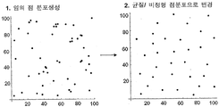
- the method of generating irregular and homogeneous reference points as described above is as follows. As shown in 1 of FIG. 11, an arbitrary point is generated in the entire area. Then, the spacing of the generated points is measured, and the points are removed when the spacing of the points is smaller than the preset value. In addition, a Delaunay triangle pattern is formed based on the points, and when the area of the triangle is larger than the preset value, a point is added inside the triangle.
- irregular and homogeneous reference points are generated as shown in FIG.
- the unit area is preferably 5 cm 2 or less, and more preferably 1 cm 2 or less when the number per unit area of the Delaunay pattern generator is uniformly adjusted.
- Number per unit area of the del Ronnie pattern generator dog 25-2500 / cm 2 is not preferable, and more preferably from 100-2000 pieces / cm 2.
- At least one of the figures constituting the pattern within the unit area may have a shape different from the remaining figures.
- the line width and line height can be made uniform.
- at least a part of the pattern of the conductive heating line may be artificially formed differently from the other patterns.
- a desired heating line pattern can be obtained.
- heating line patterns of the corresponding area and the remaining area may be different.
- the line width or line spacing of the printing pattern may be different. This can generate heat faster or more efficiently where desired.
- the heating element may include a region where the conductive heating line is not formed.
- the area where the conductive heating line is not formed may be determined according to a desired transmission / reception frequency. For example, in order to pass an electromagnetic wave of 1.6 GHz used in GPS, an area having a long side of 1/2 (9.4 cm) or more of the wavelength is required.
- the region in which the conductive heating line is not formed may have an area capable of transmitting and receiving a desired frequency, and the form thereof is not particularly limited.
- a region in which a conductive heating line is not formed may provide a heating element having one or more regions of a semicircle having a diameter of 5-20 cm.
- the conductive heating line may be blackened.
- the conductive heating line may be blackened by adding a blackening material to the paste for forming the heating line or by performing blackening treatment after printing and baking the paste.
- Blackening materials that may be added to the paste include metal oxides, carbon black, carbon nanotubes, black pigments, colored glass frits, and the like.
- the composition of the paste is 50-90 wt% of the conductive heating wire material, 1-20 wt% of the organic binder, 1-10 wt% of the blackening material, 0.1-10 wt% of the glass frit, and 1-20 wt% of the solvent. It is good to do.
- the composition of the paste is 50-90 wt% of the conductive heating wire material, 1-20 wt% of the organic binder, 0.1-10 wt% of the glass frit, and 1-20 wt% of the solvent. good.
- the blackening treatment after firing includes immersion in an oxidizing solution such as Fe or Cu ion-containing solution, immersion in a halogen ion-containing solution such as chlorine ion, immersion in hydrogen peroxide, nitric acid, and the like, and treatment with halogen gas.
- the conductive heating line pattern may be formed so that the pattern area consisting of figures of asymmetric structure is 10% or more with respect to the total pattern area.
- at least one of the lines connecting the center point of one figure constituting the Voronoi diagram with the center point of the adjacent figure forming the boundary with the figure is 10% of the total conductive heating line pattern area. It can be formed so that it may become abnormal.
- at least one side of the figure consisting of at least one triangle constituting the Delaunay pattern is formed so that the pattern area consisting of figures different in length from the other side is 10% or more with respect to the area where the pattern of the entire conductive heating line is formed. Can be.
- a large area pattern may be manufactured by using a method of designing a pattern in a limited area and then repeatedly connecting the limited area.
- the repetitive patterns may be connected to each other by fixing the positions of the points of each quadrangle.
- the limited area preferably has an area of 1 cm 2 or more, and more preferably 10 cm 2 or more.
- the line width is thin on a transparent substrate and precise conductive heating line pattern Can be formed.
- a Voronoi diagram generator or a Delaunay pattern generator can be used, thereby making it possible to easily determine a complex pattern shape.
- the Voronoi diagram generator and the Delaunay pattern generator mean points arranged to form the Voronoi diagram and the Delaunay pattern as described above.
- the scope of the present invention is not limited thereto, and other methods may be used when determining the desired pattern form.
- the printing method may be performed by transferring a paste including a conductive heating wire material onto a transparent substrate in the form of a desired pattern and then firing the paste.
- the transfer method is not particularly limited, but the pattern shape may be formed on a pattern transfer medium such as an intaglio or a screen, and a desired pattern may be transferred onto the transparent substrate using the pattern shape.
- the method of forming a pattern shape on the pattern transfer medium may use a method known in the art.
- the printing method is not particularly limited, and printing methods such as offset printing, screen printing, and gravure printing may be used.
- Offset printing may be performed by filling a paste on a patterned intaglio and then performing a primary transfer with a silicone rubber called a blanket, and then performing a secondary transfer by bringing the blanket and the transparent substrate into close contact with each other.
- Screen printing may be performed by placing the paste on a patterned screen and then placing the paste on the substrate directly through the screen where the space is empty while pushing the squeegee.
- Gravure printing may be performed by winding a blanket engraved with a pattern on a roll, filling a paste into a pattern, and then transferring the transparent substrate.
- the above schemes as well as the above schemes may be used in combination. It is also possible to use a printing method known to those skilled in the art.
- the intaglio may be manufactured by precisely etching a glass having a desired conductive heating line pattern engraved thereon, or may be metal or DLC (Diamond-like Carbon) coating on the glass surface for durability.
- the intaglio may be produced by etching a metal plate.
- an offset printing method is preferable.
- 2 illustrates an offset printing method.
- the blanket is first transferred by rotating the blanket, and the blanket is rotated as the second step to make the surface of the transparent substrate.
- the photolithography step is not limited to the printing method described above.
- a conductive heating line pattern material layer is formed on the entire surface of the transparent substrate, a photoresist layer is formed thereon, the photoresist layer is patterned by a selective exposure and development process, and then the patterned photoresist is formed.
- the layer may be used as a mask to pattern conductive heating lines and to remove the photoresist layer.
- the present invention may also utilize a photography method.
- the photosensitive material may be patterned by selective exposure and development processes. More detailed examples are as follows.
- a negative photosensitive material is apply
- a polymer film such as PET or acetyl celluloid may be used as the substrate.
- the polymer film material coated with the photosensitive material will be referred to herein as a film.
- the negative photosensitive material may generally be composed of silver halide (Silver Halide) mixed with some AgI in AgBr which is very sensitive and regular reaction to light. Since the image processed by photographing a general negative photosensitive material is negative in contrast with a subject, contrast, photographing may be performed using a mask having a pattern shape to be formed, preferably an irregular pattern shape.
- Plating may be further performed to increase the conductivity of the heating line pattern formed by using photolithography and a photolithography process.
- the plating may use an electroless plating method, and copper or nickel may be used as the plating material, and nickel plating may be performed thereon after copper plating, but the scope of the present invention is limited only to these examples. It is not.
- the present invention may also use a method using a mask.
- the mask may be patterned using a method of depositing a heating pattern material on the substrate.
- the deposition method may be thermal vapor deposition by heat or electron beam and physical vapor deposition (PVD) such as sputtering, or chemical vapor deposition (CVD) using an organometallic material. It may be.
- the transparent base material is not particularly limited, but light transmittance is preferably 50% or more, preferably 75% or more.
- glass may be used as the transparent substrate, or a plastic substrate or a plastic film may be used.
- a plastic film After forming a conductive heating line pattern, it is preferable to adhere
- the plastic substrate or film may be a material known in the art, for example, polyethylene terephthalate (PET), polyvinylbutyral (PVB), polyethylene naphthalate (PEN), polyethersulfon (PES), polycarbonate (PC), acetyl celluloid and
- PET polyethylene terephthalate
- PVB polyvinylbutyral
- PEN polyethylene naphthalate
- PS polyethersulfon
- PC polycarbonate
- acetyl celluloid acetyl celluloid
- the film of 80% or more of the same visible light transmittance is preferable. It is preferable that the thickness of the said plastic film is 12.5-500 micrometers, and it is preferable that it is 50-250 micrometers.
- the specific resistance value of the conductive heating wire material may have a value of 1 microOhm cm or more and 200 microOhm cm or less.
- the conductive heating wire material copper, silver, carbon nanotubes (CNT), or the like may be used, and silver is most preferred.
- the conductive heating wire material may be used in the form of particles. In the present invention, copper particles coated with silver may also be used as the conductive heating wire material.
- the paste when using the paste containing the conductive heating wire material, the paste may further include an organic binder in addition to the conductive heating wire material described above to facilitate the printing process. It is preferable that the organic binder has a property of volatilization in the firing process.
- the organic binders include polyacrylic resins, polyurethane resins, polyester resins, polyolefin resins, polycarbonate resins, cellulose resins, polyimide resins, polyethylene naphthalate resins, and modified epoxies. It is not limited only to.
- the paste may further include glass frit.
- the glass frit may be selected from commercially available products, but it is preferable to use an environmentally friendly glass frit free of lead.
- the glass frit used should have an average aperture of 2 micrometers or less and a maximum aperture of 50 micrometers or less.
- a solvent may be further added to the paste.
- the solvent may include butyl carbitol acetate, carbitol acetate, cyclohexanon, cellosolve acetate, terpineol, and the like. The scope of the present invention is not limited.
- the weight ratio of each component is 50-90% of the conductive heating wire material, 1-20% of the organic binder, and 0.1-10 of glass frit. % And solvent 1-20% are preferred.
- the line width of the above-mentioned conductive heating wire may be formed to be 100 micrometers or less, preferably 30 micrometers or less, more preferably 25 micrometers or less.
- a heating line pattern having conductivity is formed when the paste is printed in the above-described pattern and then subjected to a baking process.
- the firing temperature is not particularly limited, but may be 500 to 800 ° C, preferably 600 to 700 ° C.
- the transparent substrate forming the heating wire pattern is glass
- the glass may be molded to suit the intended use, such as for building or automobile, in the firing step if necessary.
- the paste may be calcined in the step of forming an automotive glass into a curved surface.
- a step of forming a bus bar electrically connected to the conductive heating line and preparing a power supply unit connected to the bus bar are performed.
- the bus bar may be formed simultaneously with the formation of the conductive heating line, or may be formed using the same or different printing method after forming the pattern.
- the conductive heating line may be formed by offset printing, and then bus bars may be formed through screen printing.
- the thickness of the bus bar is preferably 1 to 100 micrometers, preferably 10 to 50 micrometers. If it is less than 1 micrometer, the contact resistance between the conductive heating wire and the bus bar increases, which may result in local heat generation of the contacted portion. If it exceeds 100 micrometers, the electrode material cost increases.
- the connection between the bus bar and the power supply can be made through physical contact with the structure, which has good soldering and conductive heat generation.
- a black pattern may be formed.
- the black pattern may be printed using a paste containing cobalt oxide.
- screen printing is suitable for screen printing, and a thickness of 10-100 micrometers is appropriate.
- the conductive heating line and the bus bar may be formed before or after forming the black pattern, respectively.
- the heating element according to the present invention may include an additional transparent substrate provided on the side provided with the conductive heating line of the transparent substrate.
- the bonding film may be sandwiched between the conductive heating wire and the additional transparent substrate when the additional transparent substrate is bonded. Temperature and pressure can be controlled during the bonding process.
- the adhesive film is inserted between the transparent substrate on which the conductive heating wire is formed and the additional transparent substrate, and put it in a vacuum bag to increase the temperature under reduced pressure, or raise the temperature using a hot roll, By removing, primary bonding is performed.
- the pressure, temperature and time are different depending on the type of adhesive film, but the pressure is usually 300 ⁇ 700 torr, it can gradually raise the temperature from room temperature to 100 °C. At this time, the time is usually preferably within 1 hour.
- the pre-bonded laminate is subjected to the secondary bonding process by the autoclaving process of applying pressure in the autoclave and raising the temperature. Secondary bonding is different depending on the type of adhesive film, it is preferable to perform a slow cooling after 1 hour to 3 hours, preferably about 2 hours at a pressure of 140 bar or more and a temperature of about 130 ⁇ 150 °C.
- a method of bonding in one step using a vacuum laminator device may be used.
- the temperature can be gradually increased to 80 to 150 ° C. while being cooled slowly, while the pressure can be reduced to 100 ° C. ( ⁇ 5 mbar), and then pressurized ( ⁇ 1000 mbar) to join.
- any material having adhesion and becoming transparent after bonding can be used.
- PVB film, EVA film, PU film and the like can be used, but is not limited to these examples.
- the said bonding film is not specifically limited, It is preferable that the thickness is 100-800 micrometers.
- the additional transparent substrate to be bonded may be made of only a transparent substrate, or may be a transparent substrate provided with a conductive heating wire manufactured as described above.
- the line width of the conductive heating wire of the heating element is 100 micrometers or less, preferably 30 micrometers or less, more preferably 25 micrometers or less, and preferably 5 micrometers or more. It is preferable that the space
- the height of the heating wire is 1 to 100 micrometers, more preferably 3 micrometers.
- the line width and line height of the heating wire can be made uniform by the above-described methods. In the present invention, the uniformity of the heating line may be within the range of ⁇ 3 micrometers in the case of the line width, and may be within the range of ⁇ 1 micrometer in the case of the line height.
- the heating element according to the present invention may be connected to a power source for heat generation, in which the amount of heat is preferably 100 to 700 W per m 2 , preferably 200 to 300 W.
- the heating element according to the present invention has excellent heat generating performance even at low voltage, for example, 30 V or less, preferably 20 V or less, and thus may be usefully used in automobiles and the like.
- the resistance in the heating element is 5 ohms / square or less, preferably 1 ohms / square or less, more preferably 0.5 ohms / square or less.
- the heating element according to the present invention may have a shape forming a curved surface.
- the opening ratio of the conductive heating line pattern that is, the ratio of the area of the glass not covered by the pattern is preferably 70% or more.
- the heating element according to the present invention has an excellent heat generation property that can increase the temperature while maintaining an opening ratio of 70% or more and a temperature deviation of 10% or less within 5 minutes after the heating operation.
- the heating element according to the present invention may be applied to glass used in various transportation means such as automobiles, ships, railways, high speed trains, airplanes, or houses or other buildings.
- the heating element according to the present invention not only has excellent heating characteristics even at low voltage, but also minimizes side effects due to diffraction and interference of the light source after sunset, and can be formed inconspicuously with the line width as described above. Unlike technology, it can also be applied to the windshield of vehicles such as automobiles.
- the silver paste was prepared by dissolving 80% by weight silver particles having a particle diameter of 2 micrometers, 5% by weight of polyester resin, and 5% by weight of glass frit in 10% by weight of Butyl Carbitol Acetate (BCA) solvent.
- BCA Butyl Carbitol Acetate
- the intaglio used glass with Voronoi pattern 20 microns wide and 7.5 microns deep.
- a square of 0.09 mm 2 was designated as a basic unit, and a distribution of points in the basic unit was generated by giving irregularity, thereby manufacturing a Voronoi pattern as shown in FIG. 1.
- the area distribution ratio of the closed figure in this pattern was 23%.
- a silver pattern was formed on the glass substrate (100 mm x 100 mm) using an offset printer using the method shown in FIG. 2, and then fired at 600 ° C. for 3 minutes to form a silver wire as shown in FIG. 1. .
- the sheet resistance of the glass substrate was 0.6 ohm / square, and a bus bar was formed by contacting a copper strip with a clip on the pattern in a direction of 100 mm. At this time, the resistance between both terminals was 0.6 ohm.
- the calorific value of 5.4 W (540 W / m 2 ) was shown.
- the temperature rose from 20 ° C.
- the temperature deviation percentage value obtained by dividing the difference between the highest value and the lowest value of the temperature measured at 20 points by the average value was 6% or less during the measurement time.
- the visible light transmittance of the glass having the conductive heating line pattern was 80%.
- KS L 2007 Using the equipment shown in KS L 2007 from the glass substrate with the heating wire and installing a 100W incandescent lamp (using a normal light bulb of moderate brightness) at a distance of 7m, and when the light from the light source passes through the glass substrate with the heating wire was used to obtain a digital image of 1600 x 1200 pixels.
- the image has pixels within a distance of 500 with respect to the center of the light source, and the average value of the light intensity for each 5 degrees is calculated and the standard deviation value of the average values is calculated.
- the standard deviation value was 2. Also, no particular patterns due to light scattering were observed around the light source.
- the silver paste was prepared by dissolving 80% by weight of silver particles having a particle diameter of 2 micrometers, 5% by weight of polyester resin, and 5% by weight of glass frit in 10% by weight of BCA (Butyl carbitol acetate) solvent.
- BCA Butyl carbitol acetate
- the Delaunay pattern was generated by giving the irregularity in the distribution of points in the 0.09 mm2 basic unit, and then the Delaunay pattern as shown in FIG. 8 was produced.
- the area distribution ratio of the closed figure in this pattern was 20%.
- a silver pattern was formed on a glass substrate (100 mm x 100 mm) using an offset printer using the method shown in FIG. 2, and then fired at 600 ° C. for 3 minutes to form a silver wire as shown in FIG. 8. .
- the sheet resistance of the glass substrate was 1.0 ohm / square, and a bus bar was formed by contacting the copper strip with a clip on the pattern in the direction of 100 mm. At this time, the resistance between both terminals was 0.8 ohm.
- a calorific value of 5.0 W (500 W / m 2 ) was shown.
- the temperature rose from 20 ° C. to 40 ° C.
- the temperature deviation percentage value obtained by dividing the difference between the highest value and the lowest value of the temperature measured at 20 points by the average value was 6% or less during the measurement time.
- the visible light transmittance of the glass having the conductive heating line pattern was 70%.
- the standard deviation value of the light intensity for each angle was 1.5. Also, no particular patterns due to light scattering were observed around the light source.
- Example 2 In the same manner as in Example 1, only the basic unit was changed to 0.25 mm 2 .
- the pattern used at this time is as shown in FIG.
- the area distribution ratio of the closed figure in this pattern was 20%.
- the sheet resistance was 1.2 ohm / square and the resistance between both ends of the 100 mm X 100 mm glass substrate was 1.5 ohm.
- the visible light transmittance of the glass having the conductive heating line pattern was 83%.
- the standard deviation value of the light intensity for each angle was 1.4. Also, no particular patterns due to light scattering were observed around the light source.
- Example 2 In the same manner as in Example 2, only the basic unit was changed to 0.25 mm 2.
- the pattern used at this time is as shown in FIG.
- the area distribution ratio of the closed figure in this pattern was 20%.
- the sheet resistance was 1.2 ohm / square and the resistance between both ends of the 100 mm X 100 mm glass substrate was 1.0 ohm.
- the visible light transmittance of the glass having the conductive heating line pattern was 76%.
- the standard deviation value of the light intensity for each angle was 2.0. Also, no particular patterns due to light scattering were observed around the light source.
- a grid pattern based on a square of 0.09 mm 2 was produced, and the pattern is shown in FIG. 12.
- the area distribution ratio of the closed figure in this pattern was 0%.
- the sheet resistance was 0.4 ohm / square and the resistance between both ends of the 100 mm ⁇ 100 mm glass substrate was 0.4 ohm.
- the visible light transmittance of the glass having the conductive heating line pattern was 74%.
Landscapes
- Chemical & Material Sciences (AREA)
- Engineering & Computer Science (AREA)
- Life Sciences & Earth Sciences (AREA)
- Chemical Kinetics & Catalysis (AREA)
- General Chemical & Material Sciences (AREA)
- Geochemistry & Mineralogy (AREA)
- Materials Engineering (AREA)
- Organic Chemistry (AREA)
- Mechanical Engineering (AREA)
- Surface Heating Bodies (AREA)
- Resistance Heating (AREA)
- Surface Treatment Of Glass (AREA)
Abstract
Description
Claims (21)
- 투명기재, 상기 투명기재의 적어도 일면에 구비된 전도성 발열선, 상기 전도성 발열선과 전기적으로 연결된 버스 바 및 상기 버스 바와 연결된 전원부를 포함하는 발열체로서, 상기 투명기재의 전체 면적의 30% 이상이, 분포가 연속적인 폐쇄 도형들로 이루어지고, 상기 폐쇄 도형들의 면적의 평균값에 대한 표준 편차의 비율(면적 분포 비율)이 2% 이상인 전도성 발열선 패턴을 갖는 것을 특징으로 하는 발열체.
- 청구항 1에 있어서, 상기 투명기재의 전체 면적의 30% 이상이, 분포가 연속적인 폐쇄 도형들로 이루어지고, 상기 폐쇄 도형들의 면적의 평균값에 대한 표준 편차의 비율(면적 분포 비율)이 20% 이상인 전도성 발열선 패턴을 갖는 것을 특징으로 하는 발열체.
- 청구항 1에 있어서, 상기 폐쇄 도형은 적어도 100개인 것인 발열체.
- 청구항 1에 있어서, 상기 전도성 발열선은 보로노이 다이어그램을 이루는 도형들의 경계선 형태의 패턴을 갖는 것인 발열체.
- 청구항 1에 있어서, 상기 전도성 발열선은 델로니 패턴을 이루는 적어도 하나의 삼각형으로 이루어진 도형들의 경계선 형태의 패턴을 갖는 것인 발열체.
- 청구항 1에 있어서, 상기 전도성 발열선은 선폭이 100 마이크로미터 이하이고, 선간 간격이 30 mm이하이며, 투명기재 표면으로부터의 선의 높이가 1 내지 100 마이크로미터인 것인 발열체.
- 청구항 1에 있어서, 상기 투명기재의 전도성 발열선이 구비된 면에 또 하나의 투명기재가 추가로 구비된 것인 발열체.
- 청구항 1에 있어서, 직경 20 cm의 임의의 원에 대한 투과율 편차가 5% 이하인 것을 특징으로 하는 발열체.
- 청구항 1 내지 청구항 8 중 어느 하나의 항에 있어서, 발열 후 투명기재의 표면 온도의 표준 편차가 20% 이내인 것을 특징으로 하는 발열체.
- 청구항 9에 있어서, 상기 투명기재는 유리, 플라스틱 기판 또는 플라스틱 필름인 것인 발열체.
- 청구항 9에 있어서, 상기 발열체는 개구율이 70 % 이상인 것인 발열체.
- 청구항 9에 있어서, 상기 발열체는 면저항이 5 오옴/스퀘어 이하이고, 발열량이 m2 당 100 내지 500 W인 것인 발열체.
- 청구항 9에 있어서, 상기 발열체는 전도성 발열선이 이루는 패턴이 서로 다른 적어도 2개의 영역을 포함하는 것인 발열체.
- 청구항 9에 있어서, 상기 발열체는 전도성 발열선이 형성되지 않은 영역을 포함하는 것인 발열체.
- 청구항 9에 있어서, 상기 전도성 발열선은 흑화된 것인 발열체.
- 청구항 9에 있어서, 상기 발열체는 자동차 앞유리 용인 것인 발열체.
- 청구항 1 내지 청구항 8 중 어느 하나의 항에 있어서, 상기 발열체와 7m 떨어진 광원으로부터 나온 빛이 상기 발열체를 통과했을 때 측정한, 광원의 원주 방향의 각 5도당 빛의 강도의 표준 편차값이 15이하인 것인 발열체.
- 투명기재 상에 전도성 발열선을 형성하는 단계, 상기 전도성 발열선과 전기적으로 연결된 버스바를 형성하는 단계 및 상기 버스바와 연결된 전원부를 형성하는 단계를 포함하는 발열체의 제조방법으로서, 상기 전도성 발열선을, 상기 투명기재의 전체 면적의 30% 이상에, 상기 전도성 발열선과 교차하는 직선을 그렸을 때, 상기 직선과 상기 전도성 발열선의 인접하는 교점들간의 거리의 평균값에 대한 표준 편차의 비율(거리 분포 비율)이 2% 이상인 패턴으로 형성하는 것을 특징으로 하는 발열체의 제조 방법.
- 청구항 18에 있어서, 상기 전도성 발열선을 인쇄법, 포토리소그래피법, 포토그래피법, 마스크를 이용한 방법, 스퍼터링법, 또는 잉크젯 법을 이용하여 형성하는 것인 발열체의 제조방법.
- 청구항 18에 있어서, 상기 투명기재 상에 전도성 발열선의 형성 전에 보로노이 다이어그램 제너레이터 또는 델로니 패턴 제너레이터를 이용하여 상기 전도성 발열선의 패턴을 결정하는 단계를 추가로 포함하는 것인 발열체의 제조방법.
- 청구항 18에 있어서, 상기 전도성 발열선을 선폭 100 마이크로미터 이하, 선간 간격 30 mm이하, 투명기재 표면으로부터의 선의 높이 1 내지 100 마이크로미터가 되도록 형성하는 것인 발열체의 제조방법.
Priority Applications (4)
| Application Number | Priority Date | Filing Date | Title |
|---|---|---|---|
| US12/934,605 US9611171B2 (en) | 2008-06-13 | 2009-03-17 | Heating element and manufacturing method thereof |
| JP2011500697A JP5021842B2 (ja) | 2008-06-13 | 2009-03-17 | 発熱体およびその製造方法 |
| CN200980112070.3A CN101983181B (zh) | 2008-06-13 | 2009-03-17 | 加热件及其制备方法 |
| EP09762590A EP2284134B1 (en) | 2008-06-13 | 2009-03-17 | Heating element and manufacturing method thereof |
Applications Claiming Priority (6)
| Application Number | Priority Date | Filing Date | Title |
|---|---|---|---|
| KR10-2008-0055807 | 2008-06-13 | ||
| KR20080055807 | 2008-06-13 | ||
| KR10-2008-0119122 | 2008-11-27 | ||
| KR10-2008-0119121 | 2008-11-27 | ||
| KR20080119122 | 2008-11-27 | ||
| KR1020080119121A KR20090129927A (ko) | 2008-06-13 | 2008-11-27 | 발열체 및 이의 제조방법 |
Publications (1)
| Publication Number | Publication Date |
|---|---|
| WO2009151203A1 true WO2009151203A1 (ko) | 2009-12-17 |
Family
ID=43432389
Family Applications (1)
| Application Number | Title | Priority Date | Filing Date |
|---|---|---|---|
| PCT/KR2009/001336 Ceased WO2009151203A1 (ko) | 2008-06-13 | 2009-03-17 | 발열체 및 이의 제조방법 |
Country Status (6)
| Country | Link |
|---|---|
| US (1) | US9611171B2 (ko) |
| EP (1) | EP2284134B1 (ko) |
| JP (2) | JP5021842B2 (ko) |
| KR (1) | KR100940437B1 (ko) |
| CN (1) | CN101983181B (ko) |
| WO (1) | WO2009151203A1 (ko) |
Cited By (6)
| Publication number | Priority date | Publication date | Assignee | Title |
|---|---|---|---|---|
| CN102687586A (zh) * | 2009-12-29 | 2012-09-19 | Lg化学株式会社 | 加热元件及其制造方法 |
| CN102835186A (zh) * | 2010-04-01 | 2012-12-19 | Lg化学株式会社 | 加热元件及其制造方法 |
| CN103098541A (zh) * | 2010-09-14 | 2013-05-08 | Lg化学株式会社 | 加热元件及其制造方法 |
| CN103141157A (zh) * | 2011-01-13 | 2013-06-05 | Lg化学株式会社 | 加热元件及其制造方法 |
| JP2013530423A (ja) * | 2010-05-21 | 2013-07-25 | エシロール アンテルナシオナル (コンパニー ジェネラル ドプティック) | セル構造を有する透明光学部品の生産 |
| EP2631709A4 (en) * | 2010-10-22 | 2014-05-21 | Lg Chemical Ltd | DISPLAY DEVICE WITH A CONDUCTIVE STRUCTURE |
Families Citing this family (49)
| Publication number | Priority date | Publication date | Assignee | Title |
|---|---|---|---|---|
| CN101983181B (zh) | 2008-06-13 | 2015-10-14 | Lg化学株式会社 | 加热件及其制备方法 |
| US10412788B2 (en) * | 2008-06-13 | 2019-09-10 | Lg Chem, Ltd. | Heating element and manufacturing method thereof |
| KR20090129927A (ko) * | 2008-06-13 | 2009-12-17 | 주식회사 엘지화학 | 발열체 및 이의 제조방법 |
| KR101144537B1 (ko) * | 2009-07-16 | 2012-05-11 | 주식회사 엘지화학 | 전도체 및 이의 제조방법 |
| US8916805B2 (en) | 2010-01-12 | 2014-12-23 | Lg Chem, Ltd. | Heating glass and manufacturing method thereof |
| KR101314483B1 (ko) * | 2010-01-15 | 2013-10-07 | 주식회사 엘지화학 | 눈부심 방지용 발열체 |
| KR101222639B1 (ko) * | 2010-02-12 | 2013-01-16 | 성균관대학교산학협력단 | 그래핀을 이용한 유연성 투명 발열체 및 이의 제조 방법 |
| JP5385192B2 (ja) * | 2010-03-29 | 2014-01-08 | 富士フイルム株式会社 | パターン生成方法及びパターン生成プログラム |
| US20130327757A1 (en) * | 2011-01-13 | 2013-12-12 | Lg Chem, Ltd. | Heating element and method for manufacturing same |
| KR101147252B1 (ko) * | 2011-06-16 | 2012-05-18 | 경기대학교 산학협력단 | 열선 장치 |
| JP5953823B2 (ja) * | 2012-03-01 | 2016-07-20 | 大日本印刷株式会社 | ガラス板、及びガラス戸 |
| EP2830390B1 (en) * | 2012-03-21 | 2024-05-01 | LG Chem, Ltd. | Heating element and method for manufacturing same |
| JP6019662B2 (ja) * | 2012-03-28 | 2016-11-02 | 大日本印刷株式会社 | 透視性電極部材、及び画像表示装置 |
| KR101433515B1 (ko) * | 2012-04-23 | 2014-08-22 | 주식회사 엘지화학 | 발열체 및 이의 제조방법 |
| JP2013238029A (ja) * | 2012-05-15 | 2013-11-28 | Dainippon Printing Co Ltd | ガラス板、及びガラス戸 |
| EP2862946B1 (en) | 2012-06-13 | 2019-03-06 | JFE Steel Corporation | Method for continuously annealing steel strip, apparatus for continuously annealing steel strip, method for manufacturing hot-dip galvanized steel strip, and apparatus for manufacturing hot-dip galvanized steel strip |
| CN103456390B (zh) * | 2013-02-05 | 2016-04-27 | 南昌欧菲光科技有限公司 | 导电膜及其制造方法 |
| CN105247953B (zh) * | 2013-02-22 | 2018-10-19 | Lg化学株式会社 | 加热元件及其制造方法 |
| GB201404084D0 (en) | 2014-03-07 | 2014-04-23 | Pilkington Group Ltd | Glazing |
| EP3656749B1 (en) | 2014-11-17 | 2021-11-17 | Dai Nippon Printing Co., Ltd. | Heating plate, conductive pattern sheet, vehicle, and method of manufacturing heating plate |
| US10912155B2 (en) | 2014-11-17 | 2021-02-02 | Dai Nippon Printing Co., Ltd. | Heating plate, conductive pattern sheet, vehicle, and method of manufacturing heating plate |
| JP6293722B2 (ja) * | 2014-12-01 | 2018-03-14 | 大日本印刷株式会社 | 合わせガラス及び合わせガラス用パターンシート |
| WO2016119950A1 (de) * | 2015-01-26 | 2016-08-04 | Saint-Gobain Glass France | Beheizbare laminierte seitenscheibe |
| JP6722422B2 (ja) * | 2015-01-28 | 2020-07-15 | 大日本印刷株式会社 | 乗り物用ガラス、乗り物用ガラス装置 |
| JP6550804B2 (ja) * | 2015-03-12 | 2019-07-31 | 大日本印刷株式会社 | 表示体用カバー、表示体用ヒータ、信号機 |
| JP2016197513A (ja) * | 2015-04-02 | 2016-11-24 | 大日本印刷株式会社 | 照明装置用カバー、照明装置用ヒータ、照明装置 |
| JP6579433B2 (ja) * | 2015-08-21 | 2019-09-25 | 大日本印刷株式会社 | 透明発熱板及び透明発熱板を備えた乗り物 |
| WO2017086381A1 (ja) * | 2015-11-17 | 2017-05-26 | 大日本印刷株式会社 | 加熱電極装置、通電加熱ガラス、発熱板、乗り物、建築物用窓、導電体付きシート、導電性パターンシート、導電性発熱体、合わせガラスおよび導電性発熱体の製造方法 |
| JP6913294B2 (ja) * | 2015-12-16 | 2021-08-04 | 大日本印刷株式会社 | 発熱板、導電体付きシート、乗り物及び建築物用窓 |
| JP6911341B2 (ja) * | 2015-12-21 | 2021-07-28 | 大日本印刷株式会社 | 導電性発熱体、合わせガラスおよびその製造方法 |
| KR102143261B1 (ko) * | 2016-04-01 | 2020-08-10 | 주식회사 엘지화학 | 잉크 조성물, 이로 제조된 경화 패턴, 이를 포함하는 발열체 및 이의 제조방법 |
| JP2017210146A (ja) * | 2016-05-26 | 2017-11-30 | 大日本印刷株式会社 | パターン導電体、発熱用導電体、導電体付きシート、発熱板、乗り物および建築物 |
| JP6757515B2 (ja) * | 2016-06-13 | 2020-09-23 | 大日本印刷株式会社 | 合わせガラス及び乗り物 |
| JP6759764B2 (ja) * | 2016-06-30 | 2020-09-23 | 大日本印刷株式会社 | 通電加熱パネル、及び乗物 |
| USD804830S1 (en) * | 2016-06-30 | 2017-12-12 | Nta Enterprises | Textile sheet with a camouflage pattern |
| JP6905831B2 (ja) * | 2017-01-19 | 2021-07-21 | 日本板硝子株式会社 | 合わせガラス |
| JP6911501B2 (ja) * | 2017-05-09 | 2021-07-28 | 大日本印刷株式会社 | 加熱電極装置、通電加熱パネル、及び乗物 |
| US20190098703A1 (en) * | 2017-09-26 | 2019-03-28 | E I Du Pont De Nemours And Company | Heating elements and heating devices |
| KR102058865B1 (ko) * | 2018-04-12 | 2019-12-24 | (주)아이엠 | 초가속 열소재를 이용한 발열 디바이스 및 이의 제조방법 |
| KR102326674B1 (ko) * | 2018-08-29 | 2021-11-15 | 주식회사 엘지화학 | 발열체 및 이의 제조방법 |
| JP2020167047A (ja) * | 2019-03-29 | 2020-10-08 | 日東電工株式会社 | ヒータ |
| CN110107405B (zh) * | 2019-05-22 | 2021-05-28 | 江鹏 | 一种直升机发动机进气防护格栅 |
| JP2019192645A (ja) * | 2019-06-14 | 2019-10-31 | 大日本印刷株式会社 | 発熱板に用いられる導電体付シート |
| DE102020005643A1 (de) | 2020-09-15 | 2022-03-17 | Giesecke+Devrient Currency Technology Gmbh | Transparente, leitfähige Folie, Verfahren zum Herstellen derselben und Verwendung |
| DE102020006108A1 (de) | 2020-10-06 | 2022-04-07 | Giesecke+Devrient Currency Technology Gmbh | Transparente, leitfähige Folie und Verwendung derselben |
| DE102020007607A1 (de) | 2020-12-11 | 2022-06-15 | Giesecke+Devrient Currency Technology Gmbh | Leitfähige Folie, Verfahren zum Herstellen derselben und Verwendung |
| JP2023111246A (ja) * | 2022-01-31 | 2023-08-10 | 富士フイルムビジネスイノベーション株式会社 | 無端ベルト、ベルトユニット及び画像形成装置 |
| WO2024188270A1 (zh) * | 2023-03-13 | 2024-09-19 | 惠州深格光电科技有限公司 | 电加热膜、电设备、车灯组件、雷达罩和车辆 |
| CN116193655A (zh) * | 2023-03-13 | 2023-05-30 | 惠州深格光电科技有限公司 | 电加热膜 |
Citations (3)
| Publication number | Priority date | Publication date | Assignee | Title |
|---|---|---|---|---|
| KR20040012792A (ko) * | 2001-06-01 | 2004-02-11 | 쌩-고벵 글래스 프랑스 | 열선 창유리 |
| JP2006168728A (ja) * | 2004-12-18 | 2006-06-29 | Pilkington Plc | 電気加熱窓 |
| KR20080004556A (ko) * | 2005-04-01 | 2008-01-09 | 니폰샤신인사츠가부시키가이샤 | 차량용 투명 안테나 및 안테나 부착 차량용 유리 |
Family Cites Families (44)
| Publication number | Priority date | Publication date | Assignee | Title |
|---|---|---|---|---|
| FR753972A (ko) * | 1933-10-27 | |||
| NL169018C (nl) * | 1969-03-07 | 1982-05-17 | Saint Gobain | Werkwijze voor het vervaardigen van een elektrisch verwarmbare glasruit. |
| US3729616A (en) * | 1971-07-26 | 1973-04-24 | Gen Electric | Electrically heated window |
| ES201280Y (es) * | 1974-03-08 | 1976-02-01 | Orbaiceta, S. A. | Placa perfeccionada para calefaccion electrica. |
| GB2091528B (en) * | 1981-01-14 | 1984-11-07 | Boussois Sa | Heatable panels |
| DE3323670A1 (de) | 1983-07-01 | 1985-01-03 | Samuel 6080 Gross-Gerau Brustas | Sichtscheiben fuer schutzhelme od. dgl. |
| JPS62154493A (ja) * | 1985-12-26 | 1987-07-09 | 日本板硝子株式会社 | 導電性ガラス板 |
| DE3708577A1 (de) * | 1987-03-17 | 1988-09-29 | Ver Glaswerke Gmbh | Mit einer elektrisch leitenden und waermestrahlen reflektierenden schicht versehene autoglasscheibe |
| JPH02165591A (ja) * | 1988-12-20 | 1990-06-26 | Nippon Sheet Glass Co Ltd | 自動車窓用ヒータ線の導体印刷パターン作図装置 |
| JP2514073Y2 (ja) | 1989-08-24 | 1996-10-16 | 富士重工業株式会社 | 車両用ウインドシ―ルドの着霜防止装置 |
| JPH0569893U (ja) * | 1992-02-25 | 1993-09-21 | シャープ株式会社 | セラミックヒータ発熱体 |
| JPH06139845A (ja) | 1992-10-27 | 1994-05-20 | Matsushita Electric Ind Co Ltd | パターン化した透明導電膜の形成方法 |
| US5798499A (en) | 1994-07-08 | 1998-08-25 | Asahi Glass Company Ltd. | Electrically heating windshield glass having a substantially uniform thermal distribution |
| JPH0872674A (ja) | 1994-07-08 | 1996-03-19 | Asahi Glass Co Ltd | 電熱窓ガラス |
| ATE297262T1 (de) * | 1996-01-11 | 2005-06-15 | Gregory Edye Ross | Perimeter beschichtungsverfahren |
| GB9601865D0 (en) * | 1996-01-30 | 1996-04-03 | Pilkington Glass Ltd | Electrically heated window |
| JPH11322361A (ja) | 1998-05-08 | 1999-11-24 | Asahi Glass Co Ltd | 導電性ペースト及び導電体付ガラス板 |
| JP2001100235A (ja) | 1999-09-28 | 2001-04-13 | Yokogawa Electric Corp | 液晶表示装置 |
| JP2002020142A (ja) * | 2000-06-29 | 2002-01-23 | Nippon Sheet Glass Co Ltd | 車両用窓ガラスおよびその製造方法 |
| KR200287050Y1 (ko) | 2002-05-20 | 2002-08-30 | 황종하 | 산화주석코팅유리를 활용한 투명면상접합발열유리 |
| JP4223840B2 (ja) * | 2003-03-12 | 2009-02-12 | 住友化学株式会社 | フォトマスク及び拡散反射板 |
| KR20050011766A (ko) | 2003-07-23 | 2005-01-31 | 주식회사 멤스웨어 | 박막 발열체 및 그 제조방법 |
| JP2005100695A (ja) | 2003-09-22 | 2005-04-14 | Ngk Insulators Ltd | 基板加熱方法、抵抗発熱体付基板及びその製造方法 |
| DE10356607A1 (de) * | 2003-12-01 | 2005-06-30 | Bäumler, Peter | Beheizbare Glasscheibe |
| JP4629356B2 (ja) | 2004-03-31 | 2011-02-09 | 日本特殊陶業株式会社 | セラミックヒータの製造方法 |
| CN1946644A (zh) | 2004-04-28 | 2007-04-11 | 旭硝子株式会社 | 具有导电性印刷电路的玻璃板及其制造方法 |
| US7129444B2 (en) | 2004-05-17 | 2006-10-31 | Exatec Llc | High performance defrosters for transparent panels |
| KR100658187B1 (ko) | 2004-07-09 | 2006-12-15 | (주) 인브로 | 재봉기계 |
| JP4679087B2 (ja) | 2004-07-09 | 2011-04-27 | グンゼ株式会社 | 透明面状発熱体及びその製造方法 |
| JP4679088B2 (ja) | 2004-07-09 | 2011-04-27 | グンゼ株式会社 | 透明面状発熱体及びその製造方法 |
| CN101129092A (zh) * | 2005-02-24 | 2008-02-20 | 埃克阿泰克有限责任公司 | 脉冲宽度调制的除霜器 |
| US20070187383A1 (en) * | 2006-01-19 | 2007-08-16 | Wipfler Richard T | Patterned conductive elements for resistively heated glazing |
| KR100741677B1 (ko) * | 2006-03-06 | 2007-07-23 | 삼성전기주식회사 | 임프린팅에 의한 기판의 제조방법 |
| JP2007237807A (ja) | 2006-03-06 | 2007-09-20 | Fujimori Kogyo Co Ltd | 車両用窓ガラス及びその製造方法 |
| KR100953555B1 (ko) | 2006-05-03 | 2010-04-21 | 주식회사 엘지화학 | 투명한 전기 전도성 테이프 및 그 제조방법 |
| JP4971716B2 (ja) | 2006-08-10 | 2012-07-11 | 日本板硝子株式会社 | 導電性セラミックス焼結体付き車両用窓ガラス及びその製造方法 |
| EP2122638B1 (en) * | 2006-12-19 | 2012-11-07 | Dow Global Technologies LLC | Improved composites and methods for conductive transparent substrates |
| FR2913972B1 (fr) * | 2007-03-21 | 2011-11-18 | Saint Gobain | Procede de fabrication d'un masque pour la realisation d'une grille |
| CN101903341B (zh) | 2007-10-17 | 2012-10-03 | 赛诺菲-安万特 | 取代的n-苯基-联吡咯烷脲及其治疗用途 |
| DE102007050286A1 (de) * | 2007-10-18 | 2009-04-23 | Saint-Gobain Sekurit Deutschland Gmbh & Co. Kg | Transparente Scheibe mit einer elektrisch heizbaren Beschichtung |
| CN101983181B (zh) | 2008-06-13 | 2015-10-14 | Lg化学株式会社 | 加热件及其制备方法 |
| FR2936360B1 (fr) * | 2008-09-24 | 2011-04-01 | Saint Gobain | Procede de fabrication d'un masque a ouvertures submillimetriques pour grille electroconductrice submillimetrique, masque et grille electroconductrice submillimetrique. |
| FR2936358B1 (fr) * | 2008-09-24 | 2011-01-21 | Saint Gobain | Procede de fabrication d'un masque a ouvertures submillimetriques pour grille electroconductrice submillimetrique, masque a ouverture submillimetriques, grille electroconductrice submillimetrique. |
| FR2936361B1 (fr) * | 2008-09-25 | 2011-04-01 | Saint Gobain | Procede de fabrication d'une grille submillimetrique electroconductrice, grille submillimetrique electroconductrice |
-
2009
- 2009-03-17 CN CN200980112070.3A patent/CN101983181B/zh active Active
- 2009-03-17 WO PCT/KR2009/001336 patent/WO2009151203A1/ko not_active Ceased
- 2009-03-17 EP EP09762590A patent/EP2284134B1/en active Active
- 2009-03-17 US US12/934,605 patent/US9611171B2/en active Active
- 2009-03-17 KR KR1020090022806A patent/KR100940437B1/ko active Active
- 2009-03-17 JP JP2011500697A patent/JP5021842B2/ja active Active
-
2012
- 2012-02-13 JP JP2012028523A patent/JP5677338B2/ja active Active
Patent Citations (3)
| Publication number | Priority date | Publication date | Assignee | Title |
|---|---|---|---|---|
| KR20040012792A (ko) * | 2001-06-01 | 2004-02-11 | 쌩-고벵 글래스 프랑스 | 열선 창유리 |
| JP2006168728A (ja) * | 2004-12-18 | 2006-06-29 | Pilkington Plc | 電気加熱窓 |
| KR20080004556A (ko) * | 2005-04-01 | 2008-01-09 | 니폰샤신인사츠가부시키가이샤 | 차량용 투명 안테나 및 안테나 부착 차량용 유리 |
Cited By (11)
| Publication number | Priority date | Publication date | Assignee | Title |
|---|---|---|---|---|
| CN102687586A (zh) * | 2009-12-29 | 2012-09-19 | Lg化学株式会社 | 加热元件及其制造方法 |
| JP2013516043A (ja) * | 2009-12-29 | 2013-05-09 | エルジー・ケム・リミテッド | 発熱体およびこの製造方法 |
| CN102835186A (zh) * | 2010-04-01 | 2012-12-19 | Lg化学株式会社 | 加热元件及其制造方法 |
| EP2555584A4 (en) * | 2010-04-01 | 2014-12-31 | Lg Chemical Ltd | HEATING ELEMENT AND METHOD FOR MANUFACTURING THE SAME |
| JP2013530423A (ja) * | 2010-05-21 | 2013-07-25 | エシロール アンテルナシオナル (コンパニー ジェネラル ドプティック) | セル構造を有する透明光学部品の生産 |
| CN103098541A (zh) * | 2010-09-14 | 2013-05-08 | Lg化学株式会社 | 加热元件及其制造方法 |
| CN103098541B (zh) * | 2010-09-14 | 2015-06-17 | Lg化学株式会社 | 加热元件及其制造方法 |
| US9247587B2 (en) | 2010-09-14 | 2016-01-26 | Lg Chem, Ltd. | Heating element and a manufacturing method thereof |
| EP2631709A4 (en) * | 2010-10-22 | 2014-05-21 | Lg Chemical Ltd | DISPLAY DEVICE WITH A CONDUCTIVE STRUCTURE |
| US9519091B2 (en) | 2010-10-22 | 2016-12-13 | Lg Chem, Ltd. | Display device including a conductive pattern |
| CN103141157A (zh) * | 2011-01-13 | 2013-06-05 | Lg化学株式会社 | 加热元件及其制造方法 |
Also Published As
| Publication number | Publication date |
|---|---|
| CN101983181B (zh) | 2015-10-14 |
| JP2012151116A (ja) | 2012-08-09 |
| JP5677338B2 (ja) | 2015-02-25 |
| US9611171B2 (en) | 2017-04-04 |
| EP2284134A1 (en) | 2011-02-16 |
| KR20090113758A (ko) | 2009-11-02 |
| EP2284134B1 (en) | 2012-11-28 |
| EP2284134A4 (en) | 2011-07-06 |
| US20110017726A1 (en) | 2011-01-27 |
| CN101983181A (zh) | 2011-03-02 |
| KR100940437B1 (ko) | 2010-02-10 |
| JP5021842B2 (ja) | 2012-09-12 |
| JP2011518407A (ja) | 2011-06-23 |
Similar Documents
| Publication | Publication Date | Title |
|---|---|---|
| KR100940437B1 (ko) | 발열체 및 이의 제조방법 | |
| WO2009151204A1 (ko) | 발열체 및 이의 제조방법 | |
| WO2009116787A2 (ko) | 발열체 및 이의 제조방법 | |
| WO2009116786A2 (ko) | 발열체 및 이의 제조방법 | |
| WO2011081456A2 (ko) | 발열체 및 이의 제조방법 | |
| EP2928264B1 (en) | Heating element and method for manufacturing same | |
| WO2016052949A2 (ko) | 발열체 및 이의 제조방법 | |
| WO2010085097A2 (ko) | 발열체 및 이의 제조방법 | |
| WO2013141629A1 (ko) | 발열체 및 이의 제조방법 | |
| WO2012036459A2 (ko) | 발열체 및 이의 제조방법 | |
| WO2011122854A2 (ko) | 발열체 및 이의 제조방법 | |
| WO2012096541A2 (ko) | 발열체 및 이의 제조방법 | |
| KR101083883B1 (ko) | 부분 발열체 | |
| KR20110083895A (ko) | 눈부심 방지용 발열체 |
Legal Events
| Date | Code | Title | Description |
|---|---|---|---|
| WWE | Wipo information: entry into national phase |
Ref document number: 200980112070.3 Country of ref document: CN |
|
| 121 | Ep: the epo has been informed by wipo that ep was designated in this application |
Ref document number: 09762590 Country of ref document: EP Kind code of ref document: A1 |
|
| WWE | Wipo information: entry into national phase |
Ref document number: 2011500697 Country of ref document: JP |
|
| WWE | Wipo information: entry into national phase |
Ref document number: 2009762590 Country of ref document: EP |
|
| WWE | Wipo information: entry into national phase |
Ref document number: 12934605 Country of ref document: US |
|
| NENP | Non-entry into the national phase |
Ref country code: DE |