WO2009154089A1 - 高圧処理装置 - Google Patents
高圧処理装置 Download PDFInfo
- Publication number
- WO2009154089A1 WO2009154089A1 PCT/JP2009/060346 JP2009060346W WO2009154089A1 WO 2009154089 A1 WO2009154089 A1 WO 2009154089A1 JP 2009060346 W JP2009060346 W JP 2009060346W WO 2009154089 A1 WO2009154089 A1 WO 2009154089A1
- Authority
- WO
- WIPO (PCT)
- Prior art keywords
- pressure
- compartment
- processing chamber
- heat medium
- chamber
- Prior art date
- Legal status (The legal status is an assumption and is not a legal conclusion. Google has not performed a legal analysis and makes no representation as to the accuracy of the status listed.)
- Ceased
Links
Images


Classifications
-
- B—PERFORMING OPERATIONS; TRANSPORTING
- B01—PHYSICAL OR CHEMICAL PROCESSES OR APPARATUS IN GENERAL
- B01J—CHEMICAL OR PHYSICAL PROCESSES, e.g. CATALYSIS OR COLLOID CHEMISTRY; THEIR RELEVANT APPARATUS
- B01J3/00—Processes of utilising sub-atmospheric or super-atmospheric pressure to effect chemical or physical change of matter; Apparatus therefor
- B01J3/03—Pressure vessels, or vacuum vessels, having closure members or seals specially adapted therefor
-
- B—PERFORMING OPERATIONS; TRANSPORTING
- B01—PHYSICAL OR CHEMICAL PROCESSES OR APPARATUS IN GENERAL
- B01J—CHEMICAL OR PHYSICAL PROCESSES, e.g. CATALYSIS OR COLLOID CHEMISTRY; THEIR RELEVANT APPARATUS
- B01J3/00—Processes of utilising sub-atmospheric or super-atmospheric pressure to effect chemical or physical change of matter; Apparatus therefor
- B01J3/008—Processes carried out under supercritical conditions
-
- B—PERFORMING OPERATIONS; TRANSPORTING
- B01—PHYSICAL OR CHEMICAL PROCESSES OR APPARATUS IN GENERAL
- B01J—CHEMICAL OR PHYSICAL PROCESSES, e.g. CATALYSIS OR COLLOID CHEMISTRY; THEIR RELEVANT APPARATUS
- B01J3/00—Processes of utilising sub-atmospheric or super-atmospheric pressure to effect chemical or physical change of matter; Apparatus therefor
- B01J3/04—Pressure vessels, e.g. autoclaves
-
- B—PERFORMING OPERATIONS; TRANSPORTING
- B08—CLEANING
- B08B—CLEANING IN GENERAL; PREVENTION OF FOULING IN GENERAL
- B08B7/00—Cleaning by methods not provided for in a single other subclass or a single group in this subclass
- B08B7/0021—Cleaning by methods not provided for in a single other subclass or a single group in this subclass by liquid gases or supercritical fluids
-
- B—PERFORMING OPERATIONS; TRANSPORTING
- B30—PRESSES
- B30B—PRESSES IN GENERAL
- B30B11/00—Presses specially adapted for forming shaped articles from material in particulate or plastic state, e.g. briquetting presses, tabletting presses
- B30B11/001—Presses specially adapted for forming shaped articles from material in particulate or plastic state, e.g. briquetting presses, tabletting presses using a flexible element, e.g. diaphragm, urged by fluid pressure; Isostatic presses
- B30B11/002—Isostatic press chambers; Press stands therefor
-
- F—MECHANICAL ENGINEERING; LIGHTING; HEATING; WEAPONS; BLASTING
- F27—FURNACES; KILNS; OVENS; RETORTS
- F27B—FURNACES, KILNS, OVENS OR RETORTS IN GENERAL; OPEN SINTERING OR LIKE APPARATUS
- F27B17/00—Furnaces of a kind not covered by any of groups F27B1/00 - F27B15/00
- F27B17/0016—Chamber type furnaces
-
- B—PERFORMING OPERATIONS; TRANSPORTING
- B01—PHYSICAL OR CHEMICAL PROCESSES OR APPARATUS IN GENERAL
- B01J—CHEMICAL OR PHYSICAL PROCESSES, e.g. CATALYSIS OR COLLOID CHEMISTRY; THEIR RELEVANT APPARATUS
- B01J2219/00—Chemical, physical or physico-chemical processes in general; Their relevant apparatus
- B01J2219/00049—Controlling or regulating processes
- B01J2219/00051—Controlling the temperature
- B01J2219/00074—Controlling the temperature by indirect heating or cooling employing heat exchange fluids
- B01J2219/00087—Controlling the temperature by indirect heating or cooling employing heat exchange fluids with heat exchange elements outside the reactor
- B01J2219/00094—Jackets
-
- B—PERFORMING OPERATIONS; TRANSPORTING
- B01—PHYSICAL OR CHEMICAL PROCESSES OR APPARATUS IN GENERAL
- B01J—CHEMICAL OR PHYSICAL PROCESSES, e.g. CATALYSIS OR COLLOID CHEMISTRY; THEIR RELEVANT APPARATUS
- B01J2219/00—Chemical, physical or physico-chemical processes in general; Their relevant apparatus
- B01J2219/00049—Controlling or regulating processes
- B01J2219/00162—Controlling or regulating processes controlling the pressure
-
- Y—GENERAL TAGGING OF NEW TECHNOLOGICAL DEVELOPMENTS; GENERAL TAGGING OF CROSS-SECTIONAL TECHNOLOGIES SPANNING OVER SEVERAL SECTIONS OF THE IPC; TECHNICAL SUBJECTS COVERED BY FORMER USPC CROSS-REFERENCE ART COLLECTIONS [XRACs] AND DIGESTS
- Y10—TECHNICAL SUBJECTS COVERED BY FORMER USPC
- Y10T—TECHNICAL SUBJECTS COVERED BY FORMER US CLASSIFICATION
- Y10T29/00—Metal working
- Y10T29/49—Method of mechanical manufacture
- Y10T29/49805—Shaping by direct application of fluent pressure
Definitions
- the present invention relates to a high-pressure processing apparatus used for high-pressure processing using supercritical carbon dioxide, hot isostatic pressing, or the like.
- a supercritical fluid is a fluid under a temperature and pressure above a critical point, and has a feature of having both gas diffusibility and liquid solubility.
- supercritical carbon dioxide is excellent as a solvent because it evaporates below the critical point, and is actively used for dyeing, plating, water-repellent coating, etc. on resin sheets and resin films. It is being considered.
- the hot isostatic pressing process is a technique for processing an object to be processed while maintaining a high temperature and a high pressure, and is used, for example, for processing or forming cemented carbide, ceramics, and superalloy.
- Patent Literature 1 includes a pressure-resistant wall that surrounds a processing chamber and a jacket provided outside the processing chamber, and the processing chamber is heated or cooled by supplying a heat medium into the jacket. Is disclosed. In this apparatus, there is a possibility that the heating rate or cooling rate in the processing chamber can be increased by heating or cooling the heating medium in addition to heating or cooling the pressure medium introduced into the processing chamber.
- Patent Document 2 discloses a high-pressure processing apparatus including a pressure-resistant wall and an inverted cup-shaped partition wall provided inside thereof, and having a processing chamber formed inside the partition wall.
- a compartment is formed between the partition wall and the pressure-resistant wall, and the processing chamber is heated by supplying a non-reactive gas such as argon gas as a heat medium to the compartment. .
- the present invention has been made in view of the above-described problems, and can perform high-pressure processing capable of efficiently and quickly adjusting the pressure and temperature of a processing chamber without causing significant increase in size and complexity of the entire apparatus.
- An object is to provide an apparatus.
- a high-pressure processing apparatus includes a pressure-resistant vessel having a pressure-resistant wall surrounding the processing chamber and having an open end that opens the processing chamber to the outside, and an open end of the pressure-resistant vessel.
- a lid member attached to the pressure vessel so as to seal the processing chamber by sealing, a supply means for supplying a process fluid to the processing chamber, a thickness smaller than the pressure wall, By being provided along the inner surface, a compartment is formed between the inner surface and the compartment so that the process fluid does not flow into the compartment from the processing chamber in the pressure vessel.
- a heat transfer control means for controlling heat transfer between the processing chamber and the compartment by heating or cooling the heat medium outside the container and introducing the heat medium into the compartment.
- the high-pressure processing apparatus 1 has a processing chamber 3 inside, a pressure-resistant container 2 having an open end 52 that opens the processing chamber 3 in a specific direction (upward in the figure), and a pressure-resistant container 2.
- a cover member 4 that seals the inside of the container (inside the processing chamber 3) by closing the open end 52, a supply unit 5 that supplies process fluid to the processing chamber 3, and a cover member 4 and a pressure vessel 2 are provided.
- a partition wall 7 provided at a lower portion of the flange member 6. The partition wall 7 divides the inside of the pressure-resistant vessel 2 into an inner processing chamber 3 and an outer compartment 25, and both chambers 3, so that the process fluid in the processing chamber 3 does not flow into the compartment 25. Isolate 25.
- this high-pressure processing apparatus by supplying a high-temperature and high-pressure process fluid to the processing chamber 3, the object to be processed is subjected to dyeing, plating, water-repellent coating, etc. in a supercritical state, or hot isostatic pressing. Processing (HIP processing) is performed.
- the approaching direction is the inner circumferential direction (inner diameter direction). These directions coincide with the directions when the high-pressure processing apparatus 1 is used.
- the pressure vessel 2 includes a vessel body 8 which is a pressure wall and a bottom body 9.
- the container body 8 has a cylindrical shape with openings at the upper and lower ends, and the bottom body 9 is attached to the lower end of the container body 8 so as to close the lower end opening of the container body 8.
- the upper end of the container body 8 is the open end 52.
- the container body 8 is formed in a cylindrical shape around an axis along the vertical direction.
- a flange portion 11 is formed at the upper end of the container body 8 so as to protrude radially outward from the other portions.
- the flange portion 11 has a flat upper surface, and the processing chamber 3 is hermetically sealed by fitting the lid member 4 to the upper surface via the flange member 6.
- the container body 8 is formed with one insertion hole 12 at the top and bottom.
- the upper and lower insertion holes 12 and 12 are provided so as to be located diagonally across the processing chamber 3, and pass through the container body 8 in the thickness direction (radial direction) to communicate the inside and the outside of the container body 8. is doing.
- the heat medium is supplied or discharged through the upper and lower insertion holes 12 and 12.
- a heat medium is supplied into the container body 8 from the lower insertion hole 12, and the heat medium is discharged to the outside of the container body 8 through the upper insertion hole 12.
- the container body 8 is formed with an intubation hole 14 that penetrates the container body 8 in the radial direction in the same manner as the insertion hole 12.
- a fluid conduit 30 for allowing the process fluid to flow out of the container body 8 is passed through the intubation hole 14.
- the bottom body 9 is formed in a disk shape with a pressure-resistant material (for example, stainless steel) having acid resistance and pressure resistance.
- a fitting portion 16 that protrudes upward from the outer peripheral portion is formed at the center of the bottom body 9, and the fitting portion 16 is fitted to the lower end of the container body 8.
- a through hole 17 penetrating the bottom body 9 in the vertical direction is formed on the center side of the bottom body 9, and the through hole 17 is connected to a fluid path 15 described later.
- the process fluid flows into the processing chamber 3 from the through hole 17 of the bottom body 9 and is discharged to the outside from the fluid discharge hole 22 of the intubation hole 14.
- the lid member 4 has an upper lid body 18 and a lower inner lid 19, which are stacked one above the other.
- the lid body 18 is formed in a disk shape with the same material as the container body 8.
- a fitting portion 20 that projects downward from the outer peripheral portion is formed at the center of the lid body 18, and this fitting portion 20 is fitted to the upper end of the container body 8.
- the inner lid 19 is formed in a disc shape with the same pressure resistant material as the bottom body 9.
- An annular recess opened on the lower surface side of the lid body 18 is formed on the entire outer periphery of the inner lid 19, and a lip seal 21 is provided in the annular recess.
- the flange member 6 is provided between the lid member 4 and the container body 8. Although the flange member 6 is a cylindrical body, the outer peripheral edge of the upper end thereof protrudes in a hook shape toward the radially outer side than other portions.
- the eaves member 6 is attached to the container body 8 so that the protruding portion in a bowl shape is sandwiched between the lid member 4 and the container body 8.
- the fluid discharge hole 22 is formed in the saddle member 6 at a position corresponding to the intubation hole 14 of the container body 8.
- the fluid discharge hole 22 penetrates the flange member 6 in the radial direction, and the process fluid in the processing chamber 3 is discharged to the outside of the high-pressure processing apparatus 1 through the fluid discharge hole 22.
- the partition wall 7 has a cylindrical shape opened in the vertical direction.
- the upper portion of the partition wall 7 is fitted between the outer peripheral surface of the lower end portion of the flange member 6 and the inner peripheral surface of the container body 8.
- a first seal body 23 is provided on the lower outer surface of the flange member 6, and the first seal body 23 is in close contact with the inner peripheral surface of the upper end of the partition wall 7, thereby causing an airtight state in the processing chamber 3. Is preserved.
- the lower part of the partition wall 7 is fitted between the outer peripheral surface of the fitting portion 16 of the bottom body 9 and the inner peripheral surface of the lower end of the container body 8.
- the second seal body 24 is provided on the outer peripheral portion of the fitting portion 16, and the second seal body 24 is in close contact with the inner peripheral surface of the lower end of the partition wall 7, thereby airtight in the processing chamber 3. Is preserved.
- the partition wall 7 is disposed so as to cover the entire inner surface of the container body 8 below the flange member 6, thereby partitioning the inside of the pressure-resistant container 2 into an inner processing chamber 3 and an outer compartment 25. To do.
- the partition wall 7 is made of a metal material so as to be thinner than the container body 8, and is provided at a distance from the container body 8 inward in the radial direction. The partition wall 7 separates both the chambers 3 and 25 so that the process fluid does not flow into the outer compartment 25 from the inner processing chamber 3.
- the supply unit 5 includes a fluid path 15 for adjusting the temperature and pressure of the process fluid discharged from the process fluid from the processing chamber 3 and then supplying the process fluid 3 to the processing chamber 3 again.
- the process fluid may in principle be any fluid, but it is preferable to use a fluid that is excellent in diffusibility and solubility at temperatures and pressures above the critical point.
- supercritical carbon dioxide is used as the process fluid.
- the fluid path 15 is provided with the fluid conduit 30 for circulating the process fluid (supercritical carbon dioxide) from the fluid discharge hole 22 to the through-hole 17, and an evaporator 31 and a separator are disposed on the path of the fluid conduit 30.
- a condenser 33, a liquefaction tank 34, a cooler 35, a fluid pump 36, and a heater 37 are provided.
- supercritical carbon dioxide discharged from the processing chamber 3 is gasified by depressurizing the liquefied fluid by the evaporator 31.
- the carbon dioxide thus vaporized and impurities such as water mixed therein are separated by the separator 32, and only the carbon dioxide gas is recovered.
- the recovered carbon dioxide gas is sent to the condenser 33, cooled and liquefied by the condenser 33, and stored in the liquefaction tank 34.
- Carbon dioxide is released when the object to be processed of the high-pressure processing apparatus 1 is taken out, but carbon dioxide in the storage tank 38 is replenished as necessary.
- the high-pressure carbon dioxide in the liquefaction tank 34 is sent to the cooler 35 and is supercooled by the cooler 35.
- the liquefied carbon dioxide is sent to the processing chamber 3 side by the fluid pump 36.
- dyes, functionalizing agents, water, etc. are supplied from the entrainer tank 39 to the liquefied carbon dioxide by the entrainer pump and mixed. good.
- the liquefied carbon dioxide is sent to a heater 37 provided between the fluid pump 36 and the processing chamber 3.
- the liquefied carbon dioxide is heated to a temperature equal to or higher than the critical point to change to supercritical carbon dioxide, and this supercritical carbon dioxide is supplied to the processing chamber 3.
- the high-pressure processing apparatus 1 not only has a supply means 5 for supplying a process fluid set to a desired temperature in the processing chamber 3, but also a compartment 25 provided outside the processing chamber 3 via a partition wall 7.
- a heating medium path 13 for supplying or filling a heating medium adjusted to a desired temperature is provided.
- the high-pressure processing apparatus 1 includes heat transfer control means for controlling heat transfer between the process chamber 3 and the compartment 25 by introducing a heat medium into the compartment 25, and the heat transfer control means includes: A heat medium path 13 for supplying a heat medium whose temperature is set to the compartment 25 is provided.
- the compartment 25 is a cylindrical space formed between the outer diameter of the partition wall 7 and the container body 8 and can store a heat medium.
- the compartment 25 has a lower insertion hole 12 for supplying the heat medium from the heat medium path 13 into the compartment 25, and an upper side for discharging the heat medium in the compartment 25 to the heat medium path 13.
- the upper and lower insertion holes 12, 12 are connected to each other through the heat medium path 13.
- the compartment 25 is provided with convection suppression means 26 that suppresses convection of the heat medium in the compartment 25 and heat medium flow promotion means (not shown) for spreading the heat medium over the entire surface of the partition wall 7. ing.
- the convection suppressing means 26 is a structure that suppresses convection of the heat medium in the compartment 25 and is disposed in the compartment 25.
- the convection suppressing means 26 for example, a multilayer structure (for example, a honeycomb structure) in which a plurality of plates made of metal, quartz, ceramics, or the like are arranged and spaced apart from each other, or the above-described material is used.
- a porous structure for example, glass wool formed from the above.
- Such a convection suppressing means 26 is provided in the compartment 25, thereby restricting the vertical movement of the heat medium in the compartment 25, and as a result, suppresses the convection of the heat medium in the compartment 25.
- the amount of heat lost from the processing chamber due to the convection of the heat medium can be reduced. That is, heat transfer between the processing chamber and the compartment can be suppressed.
- the heat medium flow promotion means is provided on at least one of the inner peripheral surface of the container body 8 and the outer surface of the partition wall 7 so that the heat medium can be spread over the entire surface of the partition wall 7. It is done.
- the heat medium flow promoting means has a plate shape and is formed so as to protrude radially inward from the inner peripheral surface of the container body 8 or from the outer surface of the partition wall 7 toward the radially outer side. Then, the flow of the heat medium is guided so that the heat medium spreads over the entire surface of the partition wall 7.
- ribs continuously formed in the vertical direction on the outer peripheral surface of the partition wall 7, and the heat medium introduced from the lower insertion hole 12 is used as the upper insertion hole 12.
- a plate material formed in a ring shape (substantially C-shaped) with a portion in the circumferential direction cut, and the portions that are cut are overlapped at a distance so as to be staggered Things.
- the heat medium flow promoting means as described above can prevent significant deformation of the partition wall 7 even when the partition chamber 25 has a lower pressure than the processing chamber 3 and the partition wall 7 expands radially outward.
- the heating medium path 13 includes a heating medium conduit 40 for circulating the heating medium from the upper insertion hole 12 to the lower insertion hole 12.
- a heating medium conduit 40 for circulating the heating medium from the upper insertion hole 12 to the lower insertion hole 12.
- a compression means 43 for circulating the heating medium from the upper insertion hole 12 to the lower insertion hole 12.
- a heat exchanger 44 for circulating the heating medium from the upper insertion hole 12 to the lower insertion hole 12.
- a pressure equalizing conductor 41 for circulating the heating medium from the upper insertion hole 12 to the lower insertion hole 12.
- a pressure accumulator 42 for circulating the heating medium from the upper insertion hole 12 to the lower insertion hole 12.
- a heat medium pump 55 for circulating the heating medium from the upper insertion hole 12 to the lower insertion hole 12.
- a heat medium tank 56 for circulating the heating medium from the upper insertion hole 12 to the lower insertion hole 12.
- a pressure equalizing conductor 41 for circulating the heating medium from the upper insertion hole 12 to
- the heat medium discharged from the compartment 25 through the upper insertion hole 12 is sent to the compression means 43.
- the compression means 43 is a compressor or pump capable of adjusting the pressure of the discharged heat medium, and the heat medium whose pressure is adjusted by the compression means 43 is sent to the heat exchanger 44 (temperature adjustment means).
- the heat exchanger 44 heats or cools the heat medium to a predetermined temperature.
- the heat medium whose temperature has been adjusted by the heat exchanger 44 is supplied to the compartment 25 again.
- a heat medium tank 56 that receives and stores the heat medium discharged out of the compartment 25 from the upper insertion hole 12 via a conduit (not shown), and the heat medium path from the heat medium tank 56. 13 is provided with a heat medium pump 55 for sending a heat medium to the heat transfer medium 13.
- the heat transfer control means controls the heat transfer between the processing chamber 3 and the compartment 25 by heating or cooling the heat medium to an appropriate temperature and introducing it into the compartment 25, or the compartment 25 is constituted by a heat medium filled in advance.
- the heat transfer control means of the present embodiment includes the following first heat transfer control means and second heat corresponding to each of the case where the processing chamber 3 is heated or cooled, or the case where the processing chamber 3 is kept warm. There is a movement control means.
- the first heat transfer control means is used when the processing chamber 3 is heated or cooled.
- the heat exchanger 44 in the heat medium path 13 and the heat medium conduit passing through the heat exchanger 44 are used. 40.
- the first heat transfer control means heats or cools the heat medium discharged outside the compartment 25 to a predetermined temperature by the heat exchanger 44 (temperature adjusting means), and thus makes the temperature higher or lower than the processing chamber 3.
- the heat exchanger 44 temperature adjusting means
- the heat medium whose temperature is adjusted to be higher or lower than that of the processing chamber 3, that is, the heat medium whose temperature is set externally is not limited to the one that has been actually subjected to heat treatment or cooling treatment.
- This heating medium may be a fluid having a substantially constant temperature even if not heated or cooled, such as tap water, and the temperature of which is lower than the temperature of the process fluid in the processing chamber 3. .
- the second heat transfer control means is used to reduce the influence of the temperature change on the temperature of the container body 8 when the processing temperature of the processing chamber 3 is changed, and has heat insulation properties. It is composed of a medium.
- the heat medium is stored in advance in a heat medium tank 56 provided in the heat medium path 13 and is partitioned through the heat medium path 13 by the heat medium pump 55 or the compressor provided in the heat medium path 13.
- the compartment 25 may be filled in advance. This heat medium causes the compartment 25 to function as a heat insulating layer.
- a gas or liquid having a thermal conductivity of 0.2 W / mK or less, preferably 0.1 W / mK or less can be used.
- a gas or liquid having a thermal conductivity of 0.2 W / mK or less preferably 0.1 W / mK or less
- compressible gases supercritical carbon dioxide (20 MPa, 0.075 W / mK at 340 ° K), nitrogen (0.033 W / mK), argon (0.024 W / mK), etc.
- Alkyldiphenyl (0.14 W / mK at 60 ° K), fluorinated heat medium Galden HT (0.063 W / mK at 60 ° K), and the like are suitable.
- the heat transfer speed between the compartment 25 and the processing chamber 3 through the partition wall 7 can be reduced.
- the rapid temperature change of the chamber 25 can be suppressed, and the chamber 25 is pre-filled to suppress heat transfer between the chamber 25 and the processing chamber 3 through the partition wall 7.
- the chamber 3 can be kept warm.
- the temperature of the heat medium can be the same as that of the process fluid in the processing chamber 3. This further enhances the effect of suppressing heat transfer (heat exchange) between the compartment 25 and the processing chamber 3 via the partition wall 7.
- the high-pressure processing apparatus 1 has a partition wall that suppresses deformation of the partition wall 7 due to a pressure difference generated between the processing chamber 3 and the compartment 25 due to a temperature difference generated by the heat transfer control means. Protective measures are provided.
- the high-pressure processing apparatus 1 of the present embodiment includes, as partition protection means, utilization of elastic deformation of the partition 7 and pressure control means for reducing the pressure difference.
- the partition wall 7 is formed of a material that is easily elastically deformed.
- the partition wall 7 is elastically deformed so as to swell toward the processing chamber 3 when the partition chamber 25 has a higher pressure than the processing chamber 3, and the volume of the partition chamber 25 is increased by the amount of the elastic deformation.
- the pressure in the chamber 3 is equalized.
- the partition wall 7 is elastically deformed so as to be recessed toward the compartment 25 when the processing chamber 3 has a pressure higher than that of the compartment 25, and the volume of the compartment 25 is reduced by the amount of the elastic deformation. 3 is equalized.
- partition wall 7 with a material that is easily elastically deformed not only quickly equalizes the pressure in the compartment 25 and the processing chamber 3 using the elastic deformation, but also causes plastic deformation of the partition wall 7 itself. Furthermore, the effect of suppressing is produced.
- the pressure control means includes the following first pressure control means to fourth pressure control means.
- the first pressure control means is mainly constituted by the pressure equalizing conductor 41.
- the pressure equalizing device 41 includes a conducting tube (pressure tube) 45 and a moving body 46 that freely moves inside the conducting tube 45.
- One end of the conducting tube 45 communicates with the heat medium conduit 40, and the other end communicates between the heater 37 in the fluid conduit 30 and the high-pressure processing apparatus 1.
- the moving body 46 divides the inside of the conducting pipe 45 into a chamber on the heat medium conduit 40 side (the compartment 25 side) and a chamber on the fluid path 15 side (the processing chamber 3 side), and the heat medium conduit 40 side.
- the conducting tube is configured to prevent the heat medium on the (compartment 25 side) from leaking to the fluid path 15 side and the process fluid on the fluid path 15 side (processing chamber 3 side) from leaking to the heat medium path 13. It is provided in the conducting tube 45 so that the inside of the conducting tube 45 can be moved while being sealed.
- the heat medium in the heat medium conduit 40 becomes higher in pressure than the process fluid in the fluid conduit 30, and the moving body 46 moves through the conducting tube 45 toward the fluid conduit 30 due to the pressure difference.
- the chamber 25 and the processing chamber 3 are equalized by moving and making the processing chamber 3 side high pressure by the amount of movement.
- the moving body 46 moves to the heat medium conduit 40 side through the conduction pipe 45 due to a pressure difference opposite to the above, and the processing chamber 3 side is moved by the amount of the movement. By making the pressure low, the pressure in the compartment 25 and the processing chamber 3 is equalized.
- the moving body 46 since the moving body 46 immediately reacts to the pressure difference generated between the compartment 25 and the processing chamber 3, the pressure difference between the compartment 25 and the processing chamber 3 is obtained. Even when abruptly occurs, the compartment 25 and the processing chamber 3 can be pressure-balanced quickly in response to the pressure difference, and the partition wall 7 can be protected from deformation.
- the second pressure control means moves part of the heat medium or process fluid between the heat medium conduit 40 and the fluid conduit 30 to eliminate the pressure difference between the two.
- a pipe 47 provided between the conduit 30 and directly connecting the two is provided.
- the pipe 47 is provided with an open / close valve 49 which is an open / close section that can be switched between an open state for opening the pipe 47 and a closed state for closing the pipe 47.
- the on-off valve 49 may be opened only when the pressure difference between the compartment 25 and the processing chamber 3 becomes large and needs to be reduced.
- part of the heating medium or process fluid moves from the high pressure side to the low pressure side through the pipe 47, and the pressure in the compartment 25 and the processing chamber 3 is equalized.
- a pressure detector provided in each of the compartment 25 and the processing chamber 3 and a controller that opens the on-off valve when a difference between detection values of these pressure detectors exceeds a predetermined value are provided. It is also possible to realize automatic control for compression.
- omits the said on-off valve 49 is also considered.
- the piping on the upstream side of the processing chamber 3 in the pressure vessel 1 that is, the piping for supplying the process fluid to the processing chamber 3 and the piping for supplying the heat medium to the compartment 25 communicate with each other. Therefore, even if the piping 47 is always opened due to the omission of the on-off valve 49, the process fluid does not flow into the compartment 25 from the inside of the processing chamber 3. Since the process fluid flowing into the processing chamber 3 has already been subjected to the removal of impurities through the separator 32, there is a problem that even if this fluid flows into the compartment 25, the impurities are mixed into the compartment 25. Does not occur.
- the opening / closing valve 49 it is preferable to perform opening / closing by the opening / closing valve 49. Further, when it is desired to more reliably avoid mixing of the heat medium and the process fluid, only a part of the high-pressure side fluid (heat medium or process fluid) may be discharged.
- This second pressure control means can be preferably used when, for example, the heat medium and the process fluid are the same or very close in nature and can be mixed.
- the third pressure control means is mainly constituted by the compression means 43.
- the compression means 43 equalizes the pressure in the chambers 3 and 25 by increasing the pressure in the compartment 25 while the fluid pump 36 increases the pressure in the processing chamber 3.
- the pressure adjustment is performed using a pressure gauge (not shown).
- the fourth pressure control means is mainly composed of the pressure accumulator 42.
- the pressure accumulator 42 is a container that communicates with the heat medium conduit 40 and that can store a high-pressure heat medium.
- a valve 48 that can be opened and closed is provided between the container constituting the pressure accumulator 42 and the heat medium conduit 40. By opening the valve 48, the high-pressure heat medium in the container is transferred to the heat medium conduit 40. To the compartment 25. Therefore, when the processing chamber 3 becomes higher in pressure than the compartment 25, the valve 48 is opened, and a high-pressure heat medium in the container is sent to the compartment 25 through the heat medium conduit 40. The pressure in the processing chamber 3 can be equalized.
- the valve 48 can be omitted.
- a partition wall made of shrinkable rubber or the like is provided in the pressure accumulator 42, and the partition wall made of rubber or the like swells upward in the pressure accumulator 42 when the processing chamber 3 has a higher pressure than the compartment 25.
- the pressure equalization can also be achieved by compressing a high-pressure gas.
- Example 1 the high-pressure treatment apparatus 1 was used when a water-repellent coating layer was formed on the surface of a hydrocarbon-based object to be treated in the presence of supercritical carbon dioxide.
- the object to be treated is a resin piece of a predetermined size formed from a hydrocarbon resin (polyimide resin).
- the coating agent contains a monomer for the water repellent coating layer and a polymerization initiator.
- Raw material monomer is fluorine monomer (3,3,4,4,5,5,6,6,7,7,8,8,9,9,10,10,10-heptadecafluorooctylethyl methacrylate) and hydrocarbon
- a coating agent was prepared by mixing the raw material monomer and the polymerization initiator (azobisisobutyronitrile) in the same weight part. .
- water-repellent coating was performed using the object to be processed and the coating agent prepared as described above.
- a container body 8 having a thickness of 100 mm was used, and a partition wall 7 having a thickness of 5 mm was disposed along the inner surface thereof.
- the operating procedure is as follows. First, hot water at 55 ° C. is supplied from the heat medium path 13 into the compartment 25, and the first heat transfer control means generates heat transfer between the compartment 25 and the processing chamber 3 via the partition wall 7. Thus, the processing chamber 3 is adjusted to a temperature of 50 ° C. At this time, since the inside of the processing chamber 3 is open to the atmosphere, a pressure of about 0.1 MPa is applied to the heat medium.
- the fluid pump 36 sends the compressed CO 2 from the storage tank 38 through the fluid conduit 30 to the processing chamber 3.
- This CO 2 is supplied until the inside of the processing chamber 3 reaches 15 MPa.
- both the chambers 7 are equalized with the internal pressure of the processing chamber 3 while preventing the plastic deformation of the partition wall 7 by using the elastic deformation of the partition wall 7 and the first to fourth pressure control means. 3 and 25 can be boosted.
- the processing chamber 3 After the processing chamber 3 reaches 50 ° C. and 15 MPa and a certain time (about 120 minutes) has elapsed, 85 ° C. warm water is supplied from the heat medium path 13 into the compartment 25, and the first heat transfer control means is used. As a result of heat transfer between the compartment 25 and the processing chamber 3 through the partition wall 7, the process fluid in the processing chamber 3 is heated to 80 ° C. As described above, when the temperature of the processing chamber 3 is increased from 50 ° C. to 80 ° C., the polymerization initiator in the coating agent is decomposed and the copolymerization of the fluorine monomer and the hydrocarbon monomer proceeds.
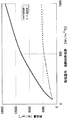
- FIG. 3 shows a result of obtaining the heat flow rate at a temperature difference of 35 ° C. transmitted from the compartment 25 to the processing chamber 3 with respect to the film heat transfer coefficient from the natural convection state to the forced convection state in the processing chamber 3. Is. As preconditions, the heat flow rate was calculated assuming that the film heat transfer coefficient on the heat medium side was 1000 W / m 2 ° C, and the thermal conductivity of the container body 8 and the partition wall 7 was 16.2 W / m ° C.
- Example 1 in FIG. 3 uses a high-pressure processing apparatus 1 provided with a container body 8 and a partition wall 7 provided on the inside thereof, and Conventional Example 1 has a partition wall 7 provided on the outside of the container body 8. Using a high-pressure processing apparatus.
- FIG. 3 shows that the heat flow amount transferred to the processing chamber 3 is larger in the first embodiment than in the first embodiment, regardless of whether the processing chamber 3 is in a natural convection state or a forced convection state.
- the high-pressure treatment apparatus 1 of Example 1 that uses the partition wall protection means can transfer heat more efficiently.
- the heat flow rate of the first embodiment is slightly larger than that of the conventional example 1, but as the forced convection state approaches.
- the heat flow rate of Example 1 tends to be much larger than that of Conventional Example 1, and in the high-pressure processing apparatus 1 of the present invention, the thermal efficiency is dramatically improved as the process fluid is supplied to the processing chamber 3 via the fluid path 15. I understand that.
- the high-pressure processing apparatus 1 is for cooling the processing chamber 3 after subjecting the object to be processed to HIP processing at a high temperature and high pressure in the processing chamber 3.
- the high-pressure treatment apparatus 1 of Example 2 includes a pressure vessel 2 having an inner diameter of 1500 mm and a partition wall 7 having a thickness of 20 mm provided inside the pressure vessel 2.
- a processing chamber 3 is formed inside the partition wall 7, and a process fluid at 150 ° C. is accommodated in the processing chamber 3.
- a compartment 25 is formed outside the partition wall 7 of the high-pressure processing apparatus 1 of the second embodiment.
- a heat medium (cooling water) having a water temperature of 35 ° C. is circulated in the compartment 25, and first heat transfer control means is provided.
- the heat passage coefficient when heat was transferred from the heat medium in the compartment 25 to the process fluid in the treatment chamber 3 was obtained by calculation.
- the high-pressure treatment apparatus 1 of Example 2 includes a container body 8 and a partition wall 7 provided on the inside thereof.
- the high-pressure treatment apparatus of Conventional Example 2 has an outer diameter of 2000 mm and an inner diameter.
- a 1500 mm container body 8 and a partition wall 7 provided outside thereof are provided.
- the heat passage coefficient K in the high-pressure processing apparatus 1 of the conventional example 2 is as follows: the outer radius r2 of the pressure vessel 2 is 1 m, the inner radius r1 of the pressure vessel 2 is 0.75 m, the process fluid heat transfer coefficient h1 and the heat medium.
- the heat transfer coefficient h2 is 400 W / m 2 K and the heat transfer coefficient ⁇ of the container body 8 is 37.3 W / mK, the following equation (1) is given.
- the high-pressure treatment apparatus 1 of the conventional example 2 is different from the second embodiment in that the high-pressure treatment apparatus 1 having the partition wall 7 inside the container body 8 is used in the second embodiment, whereas the conventional example 2 is used. Then, the point which uses the high-pressure processing apparatus 1 provided with the partition 7 in the outer side of the container main body 8 is used. Regarding points other than those described above, Conventional Example 2 is the same as Example 2, and detailed description thereof will be omitted.
- the heat passage coefficient in the high-pressure processing apparatus 1 of the conventional example 2 is given by the following formula (3) as in the case of the second embodiment.
- the amount of heat transferred from the processing chamber 3 to the compartment 25 via the partition wall 7 using the heat passage coefficient obtained by the equation (3) is expressed by the following equation (4) per 1 m of the pressure vessel.
- the high-pressure processing apparatus 1 of the present invention can efficiently cool or heat the process fluid in the processing chamber 3 even when used for HIP processing by using the heat transfer control means and the partition wall protection means in combination. It is judged that it can be done.
- the present invention is not limited to the above-described embodiments, and the shape, structure, material, combination, and the like of each member can be appropriately changed without changing the essence of the invention.
- the partition wall protection unit suppresses deformation of the partition wall 7 due to the pressure difference generated between the processing chamber 3 and the compartment 25 due to the temperature difference generated by the heat transfer control unit.
- the deformation of the partition wall 7 due to the pressure difference generated between the processing chamber 3 and the compartment 25 due to factors other than the temperature difference generated by the control means can also be suppressed.
- the use of the high-pressure treatment apparatus according to the present invention is not limited to the dyeing, plating, water-repellent coating, or HIP treatment in the supercritical fluid as described above.
- it can be used in applications other than cleaning in a supercritical fluid, HIP requiring a high-temperature and high-pressure atmosphere, and supercritical processing.
- the first heat transfer control means to the third heat transfer control means and the first to fourth pressure control means according to the embodiment may include only one of them, or a plurality of A means may be provided in combination.
- the present invention provides a high-pressure processing apparatus capable of adjusting the pressure and temperature of a processing chamber efficiently and in a short time without significantly increasing the size and complexity of the entire apparatus.
- the high-pressure processing apparatus has a pressure-resistant wall that surrounds the processing chamber and has an open end that opens the processing chamber to the outside, and seals the processing chamber by closing the open end of the pressure-resistant vessel.
- a lid member attached to the pressure vessel, supply means for supplying a process fluid to the processing chamber, a thickness smaller than the pressure wall, and provided along the inner surface of the pressure vessel.
- a partition is formed between the inner surface and a partition wall for isolating the chamber from the processing chamber so that the process fluid does not flow into the chamber from the processing chamber, and heating or cooling of the heat medium outside the container.
- heat transfer control means for controlling heat transfer between the processing chamber and the compartment by introducing the heat medium into the compartment.
- the processing space of the object to be processed can be increased by relatively increasing the processing chamber inside the partition wall. Can be bigger.
- the volume of the compartment can be reduced and the temperature of the compartment can be adjusted in a short time.
- the heat transfer control means heats the processing chamber by transferring heat from the partition to the processing chamber via the partition wall, for example, by introducing the heating medium at a temperature higher than that of the process fluid into the chamber. be able to. Conversely, by introducing the heat medium at a temperature lower than that of the process fluid into the compartment, heat can be transferred from the treatment chamber to the compartment via the partition wall to cool the treatment chamber. Furthermore, the heat transfer control means suppresses heat transfer between the process chamber and the compartment by introducing the heat medium into the compartment with the same temperature as the process fluid in the process chamber. Can also be kept warm.
- the heat transfer control means can suppress heat transfer between the processing chamber and the compartment by introducing a fluid having a heat insulating property as the heat medium into the compartment.
- the chamber can be kept warm or the temperature of the processing chamber can be changed gradually.
- the compartment is provided with convection suppressing means for suppressing convection of the heat medium in the compartment.
- This convection suppressing means can suppress the heat transfer between the processing chamber and the compartment due to the convection by suppressing the convection of the heat medium in the compartment.
- the apparatus according to the present invention further includes a heat medium flow promoting means provided on at least one of the inner surface of the pressure vessel and the outer surface of the partition so as to spread the heat medium over the entire surface of the partition. Is more preferable.
- This heat medium circulation promoting means allows the temperature control to equalize the temperature in the processing chamber by spreading the heat medium over the entire surface of the partition wall.
- the bending load corresponding to the pressure difference Acts on the septum.
- the partition wall is formed thin for the purpose of promoting heat exchange as described above, the partition wall may be plastically deformed when a large load is applied to the partition wall.
- the high-pressure processing apparatus includes pressure control means for controlling the pressure in the compartment and the pressure in the processing chamber so as to suppress the occurrence of a pressure difference between the compartment and the processing chamber.
- pressure control means for controlling the pressure in the compartment and the pressure in the processing chamber so as to suppress the occurrence of a pressure difference between the compartment and the processing chamber.
- the pressure control means includes a pressure pipe having one end communicating with the compartment and the other end communicating with the processing chamber, and the inside of the pressure pipe and the chamber on the compartment side and the chamber on the processing chamber side. And the inside of the pressure pipe is sealed while sealing the inside of the pressure pipe so as to prevent the heat medium and the process fluid from flowing between the chamber on the compartment side and the chamber on the processing chamber side.
- a movable body provided in the pressure chamber so as to be movable, and the movable body moves toward the low pressure side when the pressure difference occurs to reduce the pressure difference. Is preferred.
- This type of pressure control means can simply reduce the difference between the pressure in the compartment and the pressure in the processing chamber with a simple structure in which a moving body is provided in the pressure pipe.
- the pressure control means may include a pipe provided between the compartment and the processing chamber so as to communicate with each other, and an on-off valve which is switched between a state where the pipe is opened and a state where the pipe is closed. ,It is valid.
- the compartment and the processing chamber can be isolated by closing the on-off valve and closing the piping.
- the pressure difference can be quickly reduced by opening the on-off valve and opening the pipe only when is equal to or greater than a certain value.
- a pressure detector that detects the pressure in the compartment and the pressure in the processing chamber, and a controller that opens the on-off valve only when the difference between the two pressures detected thereby is a certain level or more.
- automatic control for reducing the pressure difference can be realized.
- the pressure control means may include a compression means for reducing the pressure difference by compressing the heat medium in the compartment, or the pressure control means may store a part of the process fluid in the processing chamber.
- a pressure accumulator that reduces the difference may be included.
- the partition wall is provided so as to be able to bend toward both the compartment side and the processing chamber side. It is also effective to reduce the pressure difference by bending toward the low pressure side when a pressure difference is generated between the compartment and the processing chamber.
- a high-pressure processing apparatus includes a pressure-resistant container having a pressure-resistant wall that surrounds the inside of the processing chamber and an open end that opens the processing chamber to the outside, and the processing chamber is closed by closing the open end of the pressure-resistant vessel.
- a lid member attached to the pressure vessel so as to be sealed, supply means for supplying a process fluid to the processing chamber, a thickness smaller than the pressure wall, and provided along an inner surface of the pressure vessel
- a partition wall is formed between the inner surface and the partition wall for isolating the chamber from the processing chamber so that the process fluid does not flow into the chamber from the processing chamber; and the processing chamber and the partition chamber And a heat medium filled in the compartment so as to suppress heat transfer between them.
- the heat medium filled in the compartments suppresses heat transfer between the treatment chambers and keeps the treatment chambers warm, or changes the temperature of the treatment chambers gently. enable.
- the function as a heat insulating layer can be given to the compartment.
Landscapes
- Chemical & Material Sciences (AREA)
- Engineering & Computer Science (AREA)
- Organic Chemistry (AREA)
- Chemical Kinetics & Catalysis (AREA)
- Mechanical Engineering (AREA)
- Physics & Mathematics (AREA)
- Fluid Mechanics (AREA)
- General Engineering & Computer Science (AREA)
- Physical Or Chemical Processes And Apparatus (AREA)
Abstract
Description


Claims (15)
- 被処理体を処理室内で高圧処理するための高圧処理装置であって、
前記処理室を内側に囲む耐圧壁を有すると共にこの処理室を外部に開放する開放端を有する耐圧容器と、
当該耐圧容器の開放端を塞いで前記処理室を密閉するように前記耐圧容器に装着される蓋部材と、
前記処理室にプロセス流体を供給する供給手段と、
前記耐圧壁よりも小さな厚みを有し、前記耐圧容器の内側面に沿って設けられることにより当該内側面との間に隔室を形成してこの隔室内に前記処理室から前記プロセス流体が流入しないように当該隔室を当該耐圧容器内において当該処理室から隔離する隔壁と、
容器外部で熱媒の加熱または冷却を行ってこの熱媒を前記隔室内に導入することにより前記処理室と前記隔室との間の熱移動を制御する熱移動制御手段とを備える、高圧処理装置。 - 前記熱移動制御手段は、前記熱媒を前記プロセス流体よりも高温にして前記隔室内に導入することにより前記隔壁を介して処理室を加熱する、請求項1に記載の高圧処理装置。
- 前記熱移動制御手段は、前記熱媒を前記プロセス流体よりも低温にして前記隔室内に導入することにより前記隔壁を介して処理室を冷却する、請求項1に記載の高圧処理装置。
- 前記熱移動制御手段は、前記熱媒を前記プロセス流体と同じ温度にして前記隔室内に導入することにより前記処理室と前記隔室との間の熱移動を抑制する、請求項1に記載の高圧処理装置。
- 前記熱移動制御手段は、前記熱媒として断熱性を有する流体を前記隔室内に導入する、請求項1記載の高圧処理装置。
- 前記隔室に設けられて当該隔室内での前記熱媒の対流を抑制する対流抑制手段をさらに備える、請求項1記載の高圧処理装置。
- 前記耐圧容器の内側面と前記隔壁の外表面の少なくとも一方の面に前記熱媒を前記隔壁の全面に行き渡らせるように設けられる熱媒流通促進部材をさらに備える、請求項1に記載の高圧処理装置。
- 前記隔室と前記処理室との間での圧力差の発生を抑制するように当該隔室内の圧力および当該処理室内の圧力を制御する圧力制御手段をさらに備える、請求項1記載の高圧処理装置。
- 前記圧力制御手段は、一端が前記隔室に連通すると共に他端が前記処理室に連通する圧力管と、この圧力管内を前記隔室側の室と前記処理室側の室とに区画し、かつ、当該隔室側の室と当該処理室側の室との間での前記熱媒および前記プロセス流体の流通を阻止するように当該圧力管内をシールしながら当該圧力管内を移動することが可能となるように当該圧力室内に設けられる移動体とを含み、この移動体は、前記圧力差が生じた際に低圧側に向かって移動することで前記圧力差を減少させる、請求項8に記載の高圧処理装置。
- 前記圧力制御手段は、前記隔室と前記処理室とを連通するように両者間に設けられる配管と、前記配管を開通する状態と前記配管を閉塞する状態とに切換えられる開閉部とを含む、請求項8に記載の高圧処理装置。
- 前記圧力制御手段は、前記隔室の熱媒を圧縮することにより前記圧力差を減少させる圧縮手段を含む、請求項8に記載の高圧処理装置。
- 前記隔壁保護手段は、前記処理室内の前記プロセス流体の一部を蓄えることにより前記圧力差を減少させる蓄圧器を含む、請求項8に記載の高圧処理装置。
- 前記隔壁は、前記隔室側と前記処理室側との双方に向かって撓むことが可能となるように設けられ、前記隔室と前記処理室との間で圧力差が生じた際に低圧側に向かって撓むことで前記圧力差を減少させる、請求項1記載の高圧処理装置。
- 被処理体を処理室内で高圧処理するための高圧処理装置であって、
前記処理室を内側に囲む耐圧壁を有すると共にこの処理室を外部に開放する開放端を有する耐圧容器と、
当該耐圧容器の開放端を塞いで前記処理室を密閉するように前記耐圧容器に装着される蓋部材と、
前記処理室にプロセス流体を供給する供給手段と、
前記耐圧壁よりも小さな厚みを有し、前記耐圧容器の内側面に沿って設けられ、当該内側面との間に隔室を形成してこの隔室内に前記処理室から前記プロセス流体が流入しないように当該隔室を当該耐圧容器内において当該処理室から隔離する隔壁と、
前記処理室と前記隔室との間での熱移動を抑制するように前記隔室内に充填される熱媒とを備える、高圧処理装置。 - 前記熱媒は断熱性を有する流体からなる、請求項14記載の高圧処理装置。
Priority Applications (3)
| Application Number | Priority Date | Filing Date | Title |
|---|---|---|---|
| EP09766537.6A EP2289615A4 (en) | 2008-06-18 | 2009-06-05 | HIGH PRESSURE TREATMENT UNIT |
| US12/988,680 US8573962B2 (en) | 2008-06-18 | 2009-06-05 | High-pressure treatment apparatus |
| KR1020107028388A KR101246416B1 (ko) | 2008-06-18 | 2009-06-05 | 고압 처리 장치 |
Applications Claiming Priority (2)
| Application Number | Priority Date | Filing Date | Title |
|---|---|---|---|
| JP2008-159202 | 2008-06-18 | ||
| JP2008159202 | 2008-06-18 |
Publications (1)
| Publication Number | Publication Date |
|---|---|
| WO2009154089A1 true WO2009154089A1 (ja) | 2009-12-23 |
Family
ID=41434005
Family Applications (1)
| Application Number | Title | Priority Date | Filing Date |
|---|---|---|---|
| PCT/JP2009/060346 Ceased WO2009154089A1 (ja) | 2008-06-18 | 2009-06-05 | 高圧処理装置 |
Country Status (6)
| Country | Link |
|---|---|
| US (1) | US8573962B2 (ja) |
| EP (1) | EP2289615A4 (ja) |
| JP (1) | JP5546164B2 (ja) |
| KR (1) | KR101246416B1 (ja) |
| TW (1) | TW201009278A (ja) |
| WO (1) | WO2009154089A1 (ja) |
Cited By (1)
| Publication number | Priority date | Publication date | Assignee | Title |
|---|---|---|---|---|
| JP2020511312A (ja) * | 2017-03-23 | 2020-04-16 | キンタス・テクノロジーズ・エービーQuintus Technologies AB | 加圧装置 |
Families Citing this family (13)
| Publication number | Priority date | Publication date | Assignee | Title |
|---|---|---|---|---|
| DE102011051269A1 (de) * | 2011-06-22 | 2012-12-27 | DIL Deutsches Institut für Lebensmitteltechnik e.V. | Beschickungsbehälter und Verfahren zur zeitgleichen Hochdruck- und Temperaturbehandlung eines Nahrungsmittels in einem Hochdruckkessel |
| DE102013202188A1 (de) | 2013-02-11 | 2014-08-14 | Robert Bosch Gmbh | Sterilisationsvorrichtung und Sterilisationsverfahren mit Energierückgewinnung |
| EP2781916A1 (en) * | 2013-03-22 | 2014-09-24 | Biotage AB | Coupling module |
| JP6189650B2 (ja) * | 2013-06-07 | 2017-08-30 | 昭和電工ガスプロダクツ株式会社 | 超臨界処理装置 |
| US10765968B2 (en) | 2014-08-19 | 2020-09-08 | Supercritical Fluid Technologies, Inc. | Systems and methods for supercritical fluid chromatography |
| EP3183047B1 (en) | 2014-08-19 | 2021-12-01 | Supercritical Fluid Technologies, Inc. | Supercritical fluid chromatography system |
| US11913685B2 (en) | 2014-08-19 | 2024-02-27 | Supercritical Fluid Technologies, Inc. | Cooling loop with a supercritical fluid system using compressed refrigerant fluid flow with a positive Joule Thomson coefficient |
| ITUB20153441A1 (it) * | 2015-09-07 | 2017-03-07 | Ghizzoni D S R L | Vano separatore posizionabile all'interno di un'autoclave di forma cilindrica con pressione bilanciata |
| FR3043922B1 (fr) * | 2015-11-25 | 2018-01-05 | Dfd - Dense Fluid Degreasing | Procede et dispositif de traitement par fluide super critique avec pompage passif gravitaire |
| WO2018071884A1 (en) | 2016-10-14 | 2018-04-19 | Supercritical Fluid Technologies, Inc. | Cooling loop with a supercritical fluid system using compressed refrigerant fluid flow with a positive joule-thomson coefficient |
| US11780192B2 (en) * | 2017-05-31 | 2023-10-10 | Quintus Technologies Ab | Pressing arrangement |
| FR3071179B1 (fr) * | 2017-09-18 | 2019-09-13 | Commissariat A L'energie Atomique Et Aux Energies Alternatives | Refroidissement de secours de presse isostatique a chaud |
| US11946915B2 (en) | 2019-01-04 | 2024-04-02 | Supercritical Fluid Technologies, Inc. | Interchangeable chromatography cartridgeadapter system |
Citations (7)
| Publication number | Priority date | Publication date | Assignee | Title |
|---|---|---|---|---|
| JPH0221193A (ja) * | 1988-07-07 | 1990-01-24 | Kobe Steel Ltd | 熱間静水圧加圧装置 |
| JPH0221189A (ja) * | 1988-07-07 | 1990-01-24 | Kobe Steel Ltd | 高温高圧処理方法並びに装置 |
| JPH0221191A (ja) * | 1988-07-07 | 1990-01-24 | Kobe Steel Ltd | 熱間静水圧加圧装置 |
| JPH02245146A (ja) * | 1989-03-18 | 1990-09-28 | Kobe Steel Ltd | 高圧処理装置 |
| JPH07268635A (ja) | 1994-03-28 | 1995-10-17 | Kobe Steel Ltd | 圧力制御方法及び反応処理装置 |
| JP2003340261A (ja) * | 2002-05-29 | 2003-12-02 | Japan Organo Co Ltd | バッチ式水熱反応器及び水熱反応装置 |
| JP2007309626A (ja) | 2006-05-22 | 2007-11-29 | Kobe Steel Ltd | 熱間等方圧加圧装置 |
Family Cites Families (8)
| Publication number | Priority date | Publication date | Assignee | Title |
|---|---|---|---|---|
| CH353341A (de) * | 1957-04-29 | 1961-04-15 | Ciba Geigy | Autoklav |
| DE3261561D1 (en) * | 1982-01-08 | 1985-01-31 | Ernst Haage Apparatebau Und La | Heatable high-pressure autoclave |
| US4670404A (en) * | 1985-04-22 | 1987-06-02 | Fike Corporation | Micro-scale chemical process simulation methods and apparatus useful for design of full scale processes, emergency relief systems and associated equipment |
| SE509518C2 (sv) * | 1997-06-13 | 1999-02-08 | Asea Brown Boveri | Anordning för varmisostatisk pressning |
| JP2003240261A (ja) * | 2002-02-15 | 2003-08-27 | Sharp Corp | 一体型空気調和機 |
| JP4204253B2 (ja) * | 2002-05-15 | 2009-01-07 | 株式会社神戸製鋼所 | 熱間等方加圧装置 |
| JP4304276B2 (ja) * | 2004-03-31 | 2009-07-29 | 独立行政法人産業技術総合研究所 | 高圧装置の効率的な断熱方法及び装置 |
| FR2891162B1 (fr) * | 2005-09-28 | 2008-05-09 | Commissariat Energie Atomique | Reacteur et procede pour le traitement d'une matiere dans un milieu reactionnel fluide |
-
2009
- 2009-06-05 KR KR1020107028388A patent/KR101246416B1/ko not_active Expired - Fee Related
- 2009-06-05 WO PCT/JP2009/060346 patent/WO2009154089A1/ja not_active Ceased
- 2009-06-05 US US12/988,680 patent/US8573962B2/en not_active Expired - Fee Related
- 2009-06-05 EP EP09766537.6A patent/EP2289615A4/en not_active Withdrawn
- 2009-06-15 TW TW098119937A patent/TW201009278A/zh not_active IP Right Cessation
- 2009-06-17 JP JP2009144305A patent/JP5546164B2/ja not_active Expired - Fee Related
Patent Citations (7)
| Publication number | Priority date | Publication date | Assignee | Title |
|---|---|---|---|---|
| JPH0221193A (ja) * | 1988-07-07 | 1990-01-24 | Kobe Steel Ltd | 熱間静水圧加圧装置 |
| JPH0221189A (ja) * | 1988-07-07 | 1990-01-24 | Kobe Steel Ltd | 高温高圧処理方法並びに装置 |
| JPH0221191A (ja) * | 1988-07-07 | 1990-01-24 | Kobe Steel Ltd | 熱間静水圧加圧装置 |
| JPH02245146A (ja) * | 1989-03-18 | 1990-09-28 | Kobe Steel Ltd | 高圧処理装置 |
| JPH07268635A (ja) | 1994-03-28 | 1995-10-17 | Kobe Steel Ltd | 圧力制御方法及び反応処理装置 |
| JP2003340261A (ja) * | 2002-05-29 | 2003-12-02 | Japan Organo Co Ltd | バッチ式水熱反応器及び水熱反応装置 |
| JP2007309626A (ja) | 2006-05-22 | 2007-11-29 | Kobe Steel Ltd | 熱間等方圧加圧装置 |
Non-Patent Citations (1)
| Title |
|---|
| See also references of EP2289615A4 |
Cited By (2)
| Publication number | Priority date | Publication date | Assignee | Title |
|---|---|---|---|---|
| JP2020511312A (ja) * | 2017-03-23 | 2020-04-16 | キンタス・テクノロジーズ・エービーQuintus Technologies AB | 加圧装置 |
| US11298905B2 (en) | 2017-03-23 | 2022-04-12 | Quintus Technologies Ab | Pressing arrangement |
Also Published As
| Publication number | Publication date |
|---|---|
| EP2289615A4 (en) | 2016-11-16 |
| KR101246416B1 (ko) | 2013-03-21 |
| JP2010023029A (ja) | 2010-02-04 |
| JP5546164B2 (ja) | 2014-07-09 |
| TW201009278A (en) | 2010-03-01 |
| KR20110020261A (ko) | 2011-03-02 |
| US8573962B2 (en) | 2013-11-05 |
| EP2289615A1 (en) | 2011-03-02 |
| US20110030186A1 (en) | 2011-02-10 |
| TWI372850B (ja) | 2012-09-21 |
Similar Documents
| Publication | Publication Date | Title |
|---|---|---|
| JP5546164B2 (ja) | 高圧処理装置 | |
| CN102192626B (zh) | 使用液态冷冻剂的冷冻器及方法 | |
| RU2548557C2 (ru) | Камера высокого давления и способ охлаждения камеры высокого давления | |
| US8323364B2 (en) | Control system for an on-demand gas generator | |
| CN104755827B (zh) | 用于容纳承压寒冷液体的密封绝缘容器 | |
| Blinov et al. | Experimental investigations and a simple balance model of a metal hydride reactor | |
| MXPA04010416A (es) | Dispositivo de congelamiento-secado. | |
| JP3123020B2 (ja) | 高純度ガスを超高圧に昇圧させる方法及び装置 | |
| AU2008222554A1 (en) | Storage tank for a cryogenic fluid with a partitioned cryogen space | |
| CN108349612B (zh) | 用于食物加工的多层容器和用于高压热加工的系统和方法 | |
| JP2013539344A5 (ja) | ||
| WO2014192506A1 (ja) | 熱間等方圧加圧装置 | |
| JP4394717B2 (ja) | 吸着冷凍システムの作動方法 | |
| JP2007010531A (ja) | 冷熱衝撃試験装置 | |
| US11204021B2 (en) | Hydrogen compressor with metal hydride | |
| JP2008215799A5 (ja) | ||
| CN108181954B (zh) | 一种用于深海采样的保低温装置 | |
| CN100539885C (zh) | 用于冷却身体的设备 | |
| NO330286B1 (no) | Kontinuerlig drevet hydrogenkompressor og fremgangsmate ved drift av denne | |
| JP2009127813A (ja) | 水素ガス供給方法およびその供給設備 | |
| WO2014083810A1 (ja) | 冷媒冷却装置及び方法 | |
| KR20250170684A (ko) | 프레스 장치 및 관련 방법 | |
| US8859153B1 (en) | Thermal conditioning fluids for an underwater cryogenic storage vessel | |
| CN120212413A (zh) | 用于深空探测器的低温推进剂在轨低损贮存系统及方法 | |
| JP2008084890A (ja) | 超臨界流体処理方法及び処理装置 |
Legal Events
| Date | Code | Title | Description |
|---|---|---|---|
| 121 | Ep: the epo has been informed by wipo that ep was designated in this application |
Ref document number: 09766537 Country of ref document: EP Kind code of ref document: A1 |
|
| WWE | Wipo information: entry into national phase |
Ref document number: 2009766537 Country of ref document: EP |
|
| WWE | Wipo information: entry into national phase |
Ref document number: 12988680 Country of ref document: US |
|
| ENP | Entry into the national phase |
Ref document number: 20107028388 Country of ref document: KR Kind code of ref document: A |
|
| NENP | Non-entry into the national phase |
Ref country code: DE |