WO2009157307A1 - 角度検出装置及びその製造方法 - Google Patents
角度検出装置及びその製造方法 Download PDFInfo
- Publication number
- WO2009157307A1 WO2009157307A1 PCT/JP2009/060564 JP2009060564W WO2009157307A1 WO 2009157307 A1 WO2009157307 A1 WO 2009157307A1 JP 2009060564 W JP2009060564 W JP 2009060564W WO 2009157307 A1 WO2009157307 A1 WO 2009157307A1
- Authority
- WO
- WIPO (PCT)
- Prior art keywords
- salient pole
- stator
- winding
- rotor
- winding member
- Prior art date
- Legal status (The legal status is an assumption and is not a legal conclusion. Google has not performed a legal analysis and makes no representation as to the accuracy of the status listed.)
- Ceased
Links
Images











Classifications
-
- G—PHYSICS
- G01—MEASURING; TESTING
- G01D—MEASURING NOT SPECIALLY ADAPTED FOR A SPECIFIC VARIABLE; ARRANGEMENTS FOR MEASURING TWO OR MORE VARIABLES NOT COVERED IN A SINGLE OTHER SUBCLASS; TARIFF METERING APPARATUS; MEASURING OR TESTING NOT OTHERWISE PROVIDED FOR
- G01D5/00—Mechanical means for transferring the output of a sensing member; Means for converting the output of a sensing member to another variable where the form or nature of the sensing member does not constrain the means for converting; Transducers not specially adapted for a specific variable
- G01D5/12—Mechanical means for transferring the output of a sensing member; Means for converting the output of a sensing member to another variable where the form or nature of the sensing member does not constrain the means for converting; Transducers not specially adapted for a specific variable using electric or magnetic means
- G01D5/14—Mechanical means for transferring the output of a sensing member; Means for converting the output of a sensing member to another variable where the form or nature of the sensing member does not constrain the means for converting; Transducers not specially adapted for a specific variable using electric or magnetic means influencing the magnitude of a current or voltage
- G01D5/20—Mechanical means for transferring the output of a sensing member; Means for converting the output of a sensing member to another variable where the form or nature of the sensing member does not constrain the means for converting; Transducers not specially adapted for a specific variable using electric or magnetic means influencing the magnitude of a current or voltage by varying inductance, e.g. by a movable armature
- G01D5/204—Mechanical means for transferring the output of a sensing member; Means for converting the output of a sensing member to another variable where the form or nature of the sensing member does not constrain the means for converting; Transducers not specially adapted for a specific variable using electric or magnetic means influencing the magnitude of a current or voltage by varying inductance, e.g. by a movable armature by influencing the mutual induction between two or more coils
- G01D5/2046—Mechanical means for transferring the output of a sensing member; Means for converting the output of a sensing member to another variable where the form or nature of the sensing member does not constrain the means for converting; Transducers not specially adapted for a specific variable using electric or magnetic means influencing the magnitude of a current or voltage by varying inductance, e.g. by a movable armature by influencing the mutual induction between two or more coils by a movable ferromagnetic element, e.g. a core
-
- Y—GENERAL TAGGING OF NEW TECHNOLOGICAL DEVELOPMENTS; GENERAL TAGGING OF CROSS-SECTIONAL TECHNOLOGIES SPANNING OVER SEVERAL SECTIONS OF THE IPC; TECHNICAL SUBJECTS COVERED BY FORMER USPC CROSS-REFERENCE ART COLLECTIONS [XRACs] AND DIGESTS
- Y10—TECHNICAL SUBJECTS COVERED BY FORMER USPC
- Y10T—TECHNICAL SUBJECTS COVERED BY FORMER US CLASSIFICATION
- Y10T29/00—Metal working
- Y10T29/49—Method of mechanical manufacture
- Y10T29/49002—Electrical device making
- Y10T29/49009—Dynamoelectric machine
- Y10T29/49012—Rotor
-
- Y—GENERAL TAGGING OF NEW TECHNOLOGICAL DEVELOPMENTS; GENERAL TAGGING OF CROSS-SECTIONAL TECHNOLOGIES SPANNING OVER SEVERAL SECTIONS OF THE IPC; TECHNICAL SUBJECTS COVERED BY FORMER USPC CROSS-REFERENCE ART COLLECTIONS [XRACs] AND DIGESTS
- Y10—TECHNICAL SUBJECTS COVERED BY FORMER USPC
- Y10T—TECHNICAL SUBJECTS COVERED BY FORMER US CLASSIFICATION
- Y10T29/00—Metal working
- Y10T29/49—Method of mechanical manufacture
- Y10T29/49002—Electrical device making
- Y10T29/4902—Electromagnet, transformer or inductor
- Y10T29/49071—Electromagnet, transformer or inductor by winding or coiling
Definitions
- the present invention relates to an angle detection device and a manufacturing method thereof.
- this type of resolver has a stator and a rotor, and utilizes the fact that the mutual inductance between the stator and the rotor varies depending on the rotational position of the rotor with respect to the stator, and outputs according to the rotational angle of the rotor with respect to the stator. Output a signal.
- FIG. 28 is a diagram for explaining a conventional resolver.
- FIG. 28A is a diagram showing a structure of a conventional resolver
- FIG. 28B is a diagram shown for explaining a winding structure in each slot of the conventional resolver.
- the conventional resolver 10 includes a one-phase excitation winding 14 and a two-phase detection winding (a SIN detection winding 16 and a COS detection winding 17 (FIG. 28A). (Not shown)) is a variable reluctance resolver including a stator 11 wound around a salient pole 13 and a rotor 15 provided to be rotatable with respect to the stator 11.
- the rotor 15 is an eccentric rotor that is an iron core only and does not have a winding.
- the gap permeance between the rotor 15 and the stator 11 changes in a sine wave shape with respect to the rotation angle ⁇ . For this reason, according to the conventional resolver 10, as shown in FIG. 28B, the rotation angle can be detected with high accuracy by measuring the gap permeance described above.
- two-phase detection windings (SIN detection winding 16 and COS detection winding 17) are sequentially wound in each slot with one slot pitch (without slot skipping). (Not shown in FIG. 28 (a)), and further, as shown in FIG. 28 (b), distributed winding is performed such that the induced voltage distribution is a sinusoidal distribution. (The number of turns (amount) of the windings is also a sinusoidal distribution).
- the detection accuracy of the rotation angle can be improved by reducing the high-frequency order from the low order to the high order included in the output voltage.
- Patent Document 1 and Patent Document 2 for example, an excitation winding and a detection winding are provided on a bobbin provided on the stator side, or an excitation winding and a detection winding are printed on a multilayer printed board on the stator side.
- an angle detection device is disclosed in which salient poles and rotors are formed of metal plates or the like.
- the angle detection devices disclosed in Patent Document 1 and Patent Document 2 have a problem that the number of parts is large, and it is difficult to reduce the manufacturing cost and improve the reliability of the angle detection device.
- protrusions are present on the inner diameter side of the stator, for example, by cutting and raising the yoke of the stator, thereby improving the magnetic efficiency between the stators. It was difficult to improve the detection accuracy.
- the present invention has been made in view of the technical problems as described above.
- the object of the present invention is to reduce the number of parts to reduce costs and improve reliability, and to further improve detection accuracy.
- An object of the present invention is to provide an improved angle detection device and a manufacturing method thereof.
- the present invention has a plurality of salient pole portions formed on the inner peripheral side of an annular flat plate made of a magnetic material and raised by bending, and each salient pole portion serves as a winding core.
- the gap permeance between the stator provided with the winding member for excitation and the winding member for detection and the outer peripheral surface of each salient pole portion is changed by rotation around the rotation axis.
- the present invention relates to an angle detection device including a rotor that is rotatably provided to the stator.
- a stator having a plurality of salient pole portions formed on a flat plate is bent to cause the plurality of salient pole portions, and by rotating around the rotation axis, the outer peripheral surface of each salient pole portion and the inner side of the rotor Since the rotor is provided so that it can rotate with respect to the stator so that the gap permeance with the peripheral surface changes, the number of parts is greatly reduced without lowering the detection accuracy, and the cost and reliability are reduced. It is possible to provide an angle detection device that improves the above.
- the minimum inner diameter of the stator after the bending process may be an inner diameter of each salient pole portion.
- the magnetic efficiency is improved by the magnetic circuit via the salient pole portion, and the transformation ratio of the angle detection device is increased. Will be able to.
- the present invention also has a plurality of salient pole portions formed on the outer peripheral side of an annular flat plate made of a magnetic material and raised by bending, and each exciting pole portion serves as a winding magnetic core, and an exciting winding member,
- the stator is provided with a winding member for detection, and is made of a magnetic material.
- the gap permeance between the salient pole portion and the inner peripheral surface of the stator is changed by rotation around the rotation axis.
- an angle detection device including a rotor rotatably provided.
- a stator having a plurality of salient pole portions formed on a flat plate is bent to cause the plurality of salient pole portions, and by rotating around the rotation axis, the inner peripheral surface of each salient pole portion and the rotor Since the rotor is provided so that it can rotate with respect to the stator so that the gap permeance between the outer peripheral side and the outer surface changes, the number of parts is greatly reduced without lowering the detection accuracy, and the cost and reliability are reduced. It is possible to provide an angle detection device that improves the above.
- the maximum outer diameter of the stator after the bending process may be an outer diameter at each salient pole portion.
- the magnetic efficiency is improved by the magnetic circuit via the salient pole part, and the transformation ratio of the angle detection device is increased. To be able to.
- the tip shape of each salient pole part has a T-shape
- the winding member for excitation around the support part that supports the tip part of each salient pole part A winding member for detection may be provided.
- the tip shape of the salient pole portion provided with the winding member a T-shaped shape, it is possible to reduce the variation in magnetic efficiency with respect to the thrust direction deviation of the rotor. Thereby, the influence of the magnetic flux change in the vicinity of the winding member can be reduced, and the detection accuracy of the rotation angle of the rotor relative to the stator can be improved.
- a T-shaped shape as the tip shape of the salient pole part, even when the number of salient pole parts is increased, it is possible to suppress a decrease in magnetic flux passing through the winding core, resulting in a decrease in detection accuracy. Can be suppressed.
- the material of the stator may be SPCC which is ordinary steel or S45C which is carbon steel for machine structure.
- a stator by using SPCC or S45C, which is easy to maintain processing accuracy and reliability by bending, as a stator material, a stator is prepared with an inexpensive material, and a low-cost and highly reliable angle detection device is provided. Can be provided.
- the angle detection device may include a converter that outputs a digital signal corresponding to an output signal from the winding member in accordance with a rotation angle of the rotor with respect to the stator.
- an angle detection device that can reduce the cost and improve the reliability, further improve the detection accuracy, and output a digital signal corresponding to the rotation angle of the rotor.
- the present invention also includes a bending step of bending the plurality of salient pole portions of the stator formed on the inner peripheral side of the annular flat plate made of a magnetic material so as to be raised with respect to the flat plate surface, and the plurality of salient pole portions.
- the present invention relates to a method of manufacturing an angle detection device including a rotor mounting step of mounting a rotor that is rotatable with respect to the stator so that a gap permeance between each salient pole portion and the outer peripheral surface changes.
- the bending step can be performed such that the minimum inner diameter of the stator after the bending process is the inner diameter of each salient pole portion.
- the present invention also includes a bending step of bending a plurality of salient pole portions of the stator formed on the outer peripheral side of an annular flat plate made of a magnetic material so as to be raised with respect to the flat plate surface, and each of the plurality of salient pole portions.
- the present invention relates to a method of manufacturing an angle detection device including a rotor mounting step of mounting a rotor that is rotatable with respect to the stator so that a gap permeance between each salient pole portion and the inner peripheral surface changes.
- the bending step can be performed such that the maximum outer diameter of the stator after the bending process is the outer diameter of each salient pole portion.
- the tip shape of each salient pole part of the stator has a T-shape, and the excitation is provided around a support part that supports the tip part of each salient pole part.
- Winding members for detection and the winding member for detection may be provided.
- the stator may be made of SPCC, which is ordinary steel, or S45C, which is carbon steel for mechanical structure.
- an angle detection device that reduces the number of parts to reduce the cost and improve the reliability and further improve the detection accuracy at a low cost.
- FIG. 2A is an explanatory view of a winding member for excitation provided in the salient pole portion of the stator in the first embodiment.
- FIG. 2B is an explanatory view of a winding member for detection provided at the salient pole portion of the stator in the first embodiment.
- the top view of the resolver of FIG. Explanatory drawing of the magnetization characteristic of the material of a stator.
- FIG. 3 is an explanatory diagram schematically illustrating the shape of salient pole portions in the first embodiment.
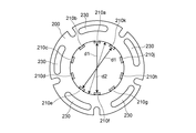
- FIG. 3 is a top view of the stator in the first embodiment.
- FIG. 3 is a flowchart of an example of a resolver manufacturing method according to the first embodiment.
- FIG. 1 is a functional block diagram of a configuration example of an angle detection system in Embodiment 1.
- FIG. 6 is a perspective view of a configuration example of a stator that constitutes a resolver according to a first modification of the first embodiment.
- FIG. 6 is a perspective view of a configuration example of a resolver in a first modification of the first embodiment.
- FIG. 9 is a perspective view of a configuration example of a stator in a second modification of the first embodiment.
- FIG. 6 is a perspective view of a configuration example of a resolver in a second modification example of the first embodiment.
- the perspective view of the structural example of the stator which comprises the resolver in the 3rd modification of Embodiment 1.
- FIG. FIG. 10 is a perspective view of a configuration example of a resolver in a third modification of the first embodiment.
- the perspective view of the structural example of the resolver in Embodiment 2 which concerns on this invention.
- FIG. 6 is a top view of a stator in Embodiment 2.
- FIG. 12 is a perspective view of a configuration example of a stator in a first modification of the second embodiment.
- FIG. 10 is a perspective view of a configuration example of a resolver in a first modification of the second embodiment.
- FIG. 28A shows a structure of a conventional resolver.
- FIG. 28B is an explanatory view of a winding structure in each slot of the conventional resolver.
- a resolver will be described as an example of the angle detection device according to the present invention, but the present invention is not limited to the resolver.
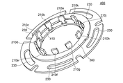
- FIG. 1 is a perspective view of a configuration example of a resolver according to the first embodiment of the present invention.
- illustration of wiring is omitted.
- FIG. 1 a single-phase excitation two-phase output type resolver having ten salient pole portions will be described as an example, but the present invention is not limited to this.
- the resolver 100 is a so-called inner stator type / outer rotor type angle detection device. That is, the edge (circumferential portion) constituting the inner diameter of the annular body (rotor or stator) in plan view is the inner peripheral side (the inner diameter side, the side closer to the annular central portion), and the outer diameter of the annular body is configured. When the edge portion (circumferential portion) is the outer peripheral side (the outer diameter side, the side far from the annular central portion), a magnetic path is formed between the salient pole portion of the annular stator on the inner peripheral side of the annular rotor.
- outer peripheral surface (outer peripheral surface) of the salient pole portion of the stator faces the inner peripheral surface (inner peripheral surface) of the rotor, and the detection winding provided on the stator according to the rotation angle of the rotor The signal from changes.
- the resolver 100 includes a stator (stator) 200 and a rotor (rotor) 300.
- the stator 200 is provided on the inner peripheral side (side closer to the center of the annular flat plate) of a ring-shaped flat plate made of a magnetic material, and then is projected on the flat plate surface. It has pole parts 210a, 210b, 210c, 210d, 210e, 210f, 210g, 210h, 210j, and 210k. These salient pole portions are formed on the inner (inner diameter side) edge of the annular flat plate, and the outer peripheral surface of each salient pole portion facing the rotor 300 is not a flat surface but centered on the central portion of the annular flat plate. Forming part of an arc.
- each salient pole portion is provided with a winding member for excitation and a winding member for detection as a winding core. That is, the salient pole part 210a is provided with a winding member 220a for excitation and detection as a winding magnetic core, and the salient pole part 210b is provided with a winding for excitation and detection as a winding magnetic core. A member 220b is provided, the salient pole part 210c is provided with a winding member 220c for excitation and detection as a winding magnetic core, and the salient pole part 210d is provided with an excitation and detection as a winding magnetic core.
- the winding member 220d is provided, and the salient pole portion 210e is provided with a winding member 220e for excitation and detection as a winding magnetic core.
- the salient pole portion 210f is provided with a winding member 220f for excitation and detection as a winding magnetic core
- the salient pole portion 210g is provided with a winding for excitation and detection as a winding magnetic core.
- the wire member 220g is provided, the salient pole portion 210h is provided with a winding member 220h for excitation and detection as a winding magnetic core, and the salient pole portion 210j is provided with a winding core for excitation and A winding member 220j for detection is provided, and the salient pole portion 210k is provided with a winding member 220k for excitation and detection as a winding magnetic core.
- the salient pole portions 210a to 210k of the stator 200 are formed in advance on a flat plate and then raised so as to be substantially perpendicular to the flat plate surface by bending press processing (bending processing in a broad sense).
- the stator 200 has a plurality of mounting holes 230 (five in FIG. 1) that are longer in the circumferential direction than in the radial direction. Accordingly, the resolver 100 is configured such that a fixing member (not shown) can be attached to a given fixing plate (not shown) through the attachment holes 230. Thus, by forming the attachment hole 230 so as to be long in the circumferential direction of the stator 200, fine adjustment of the fixed position of the resolver 100 with respect to the rotation direction of the rotor 300 can be easily performed.
- the rotor 300 is made of a magnetic material and is provided so as to be rotatable with respect to the stator 200. More specifically, the rotor 300 is rotatable with respect to the stator 200 so that the gap permeance between the salient pole portions of the stator 200 and the outer peripheral surface changes due to the rotation of the rotor 300 about the rotation axis. Provided.
- FIG. 2 (a) and 2 (b) are explanatory diagrams of winding members provided on salient pole portions of the stator 200.
- FIG. FIG. 2A shows an explanatory diagram of a winding member for excitation.
- FIG. 2B shows an explanatory view of a winding member for detection.
- 2 (a) and 2 (b) are plan views of the resolver 10 viewed in the direction of the rotation axis of the rotor 300 of FIG. 1. The same parts as those in FIG. To do.
- illustration of the rotor 300 is abbreviate
- FIG. 2A the winding direction of the excitation winding as the winding member for excitation is schematically shown by a wavy line
- FIG. 2B the winding direction of the detection winding as the detection winding member is shown. Is schematically shown by a wavy line.
- the winding member for excitation is provided such that the winding directions of the winding members provided at the adjacent salient pole portions are opposite to each other.
- the winding member for excitation provided in each salient pole part can be a coil winding, for example.
- An excitation signal is given between the windings R1 and R2 constituting such a winding member for excitation.
- the detection winding member is composed of two sets of winding members.
- the winding member for detection for obtaining the detection signal of the first phase (for example, SIN phase) of the two-phase detection signals is, for example, every other one from the salient pole part 210a to the salient pole part 210j counterclockwise. It is wound around the salient pole part.
- every other winding member for detection for obtaining a detection signal of the second phase (for example, COS phase) of the two-phase detection signals is, for example, from the salient pole part 210k to the salient pole part 210n counterclockwise. Is wound around each salient pole part.
- the first phase detection signal is detected as a signal between the windings S1 and S3, and the second phase detection signal is detected as a signal between the windings S2 and S4.
- the winding member for detection provided in each salient pole portion can be, for example, a coil winding.
- the winding direction of the exciting winding member is not limited to the direction shown in FIG.
- the winding direction of the detection winding member is not limited to the direction shown in FIG.
- the following magnetic circuit is formed by the rotation of the rotor 300 with respect to the stator 200.
- FIG. 3 shows a top view of the resolver 100 of FIG.
- FIG. 3 is a plan view of the resolver 100 viewed in the direction of the rotation axis of the rotor 300 of FIG. 1, and the same parts as those in FIG. 1 or FIG.
- FIG. 3 schematically shows the direction of the magnetic flux at a certain time when the rotor 300 is rotating with respect to the stator 200.
- FIG. 3 the direction of the magnetic flux passing through each salient pole as the winding core is schematically shown, and the direction of the magnetic flux between the salient poles is indicated by a wavy line.
- a winding member is provided at each salient pole portion of the stator 200.
- the winding member is provided in each salient pole portion so that the direction of the magnetic flux passing through the adjacent salient pole portions is opposite.
- the current generated in the winding member wound around each salient pole portion also changes according to the change in gap permeance between each salient pole portion.
- the waveform of the current generated in can be made sinusoidal.
- the material of the stator 200 made of a magnetic material is SPCC (one steel plate) that is ordinary steel or S45C (one piece of carbon steel for mechanical structure) rather than a laminated electromagnetic steel plate.
- SPCC Step Plate Cold Commercial
- S45C is a carbon steel material for machine structure defined in JIS G 4051, and contains about 0.45% carbon.
- FIG. 4 shows an explanatory diagram of the magnetization characteristics of the stator material.
- the horizontal axis of FIG. 4 is the magnetic field strength (unit: H [A / m]), and the vertical axis is the magnetic flux density (unit: B [T]).
- a steel sheet such as SPCC or S45C
- the magnetic flux density is saturated above a certain magnetic field.
- T1 laminated electromagnetic steel sheets
- SPCC and S45C are saturated with lower magnetic flux density (T2). That is, when the laminated electromagnetic steel sheet is adopted as the material of the stator 200, a higher magnetic flux density can be obtained. As a result, the detection level of the detection signal can be increased. Therefore, when SPCC or S45C is adopted as the material of the stator 200, the detection level of the detection signal is low because the magnetic flux density is low.
- the laminated electrical steel sheet is not only expensive as a material cost, but also has a property that it is weak to bending by bending press working and it is difficult to maintain processing accuracy and reliability by bending.
- SPCC and S45C have the property of being inexpensive as a material cost, resistant to bending by bending press processing, and easily maintaining processing accuracy and reliability by bending. Therefore, by adopting SPCC or S45C as the material of the stator 200 and forming the salient pole as shown in FIG. 1 by bending, the stator 200 can be prepared with an inexpensive material. . Moreover, even if the detection level is low, the detection accuracy does not decrease. By amplifying the detection level of the detection signal, the cost of the resolver can be reduced without reducing the detection accuracy. .
- the tip shape of each salient pole portion has a T-shape, and an excitation winding member and a detection winding are provided around a support portion that supports the tip portion of each salient pole portion.
- a member is provided.
- FIG. 5 is an explanatory diagram schematically showing the shape of the salient pole part in the first embodiment.
- FIG. 5 shows a plan view of the tip of the salient pole part 210a provided on the annular flat plate surface, but the shape of the other salient pole part is the same as that of FIG.
- the salient pole part 210a has a tip part 212a and a support part 214a, and is formed so that the tip shape of the salient pole part 210a is a T-shape.
- a tip part 212a and a support part 214a are raised with respect to a flat plate surface by bending.
- W1 is the width of the surface of the support portion 214a facing the rotor 300 (of the rotor 300). Width in rotation direction) is larger than W2.
- the exciting winding member shown in FIG. 2A and the detecting winding member shown in FIG. 2B are provided so as to be wound around the outer side of the support portion 214a.
- the tip shape of the salient pole portion provided with the winding member a T-shaped shape
- the influence of the magnetic flux change in the vicinity of the winding member can be reduced, and the detection accuracy of the rotation angle of the rotor 300 relative to the stator 200 can be improved.
- a T-shaped shape as the tip shape of the salient pole part even when the number of salient pole parts is increased, it is possible to suppress a decrease in magnetic flux passing through the winding core, resulting in a decrease in detection accuracy. Can be suppressed.
- the resolver 100 since the resolver 100 according to the first embodiment includes the stator 200, the rotor 300, and the winding member, a resolver having a complicated configuration with a large number of parts as in Patent Document 1 or Patent Document 2 is manufactured. Compared to the case, the number of parts can be greatly reduced, and the cost can be reduced and the reliability can be improved.
- stator 200 an inexpensive magnetic material having high processing accuracy and reliability for the bending process is adopted, so that the cost of the resolver 100 can be reduced.
- FIG. 6 shows a top view of the stator 200 in the first embodiment.
- the same parts as those in FIG. 6 are identical to FIG. 6, the same parts as those in FIG.
- the stator 200 according to the first embodiment has no salient protrusion on the inner diameter side of the stator 200 by raising the salient pole portion with respect to the flat plate surface by bending press processing. That is, the minimum inner diameter of the stator 200 after bending is the inner diameter d1 at each salient pole portion. More specifically, among the inner diameters of the stator 200, the inner diameter d ⁇ b> 1 at each salient pole part is smaller than the inner diameter d ⁇ b> 2 between two adjacent salient pole parts among the inner diameters of the stator 200.
- the magnetic efficiency is improved by the magnetic circuit via the salient pole portion, and the transformation ratio of the resolver 100 can be increased. become able to.
- the cost can be reduced and the reliability can be improved and the transformation ratio can be increased without reducing the detection accuracy.
- FIG. 7 is a flowchart illustrating an example of a method for manufacturing the resolver 100 according to the first embodiment.
- the resolver 100 manufacturing apparatus executes the process of each process according to the flow shown in FIG.
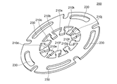
- FIG. 8 is a perspective view of the stator 200 according to the first embodiment before bending press processing.
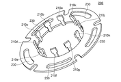
- FIG. 9 is a perspective view of the stator 200 in the first embodiment after bending press processing. 9, the same parts as those in FIG. 8 are denoted by the same reference numerals, and description thereof will be omitted as appropriate.
- FIG. 10 is a perspective view of the stator 200 in the first embodiment after the winding member attaching step.
- FIG. 10 the same parts as those in FIG. 1 or FIG.
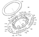
- FIG. 11 is an explanatory diagram of a rotor attachment process in the first embodiment.
- the resolver 100 first processes the shape of the stator 200 in the stator shape processing step (step S10), and then bends the salient pole portions of the plate-shaped stator 200 in the bending press processing step (bending step).
- a plurality of salient pole portions are raised with respect to the flat plate surface (step S12).
- each salient pole portion of salient pole portions 210a to 210k raised in step S12 is used as a winding core, and a winding member is provided outside each salient pole portion (step S14). .
- stator shape processing step of Step S10 in order to perform the bending press processing of Step S12, as shown in FIG. 8, by using press processing, SPCC which is ordinary steel or S45C which is carbon steel for mechanical structure is used as a material.
- the shape of the stator 200 is formed by forming salient pole portions 210a to 210k and attachment holes 230 at the inner diameter side edge of the flat plate made of the annular magnetic material. At this time, as described with reference to FIG. 5, the stator 200 is formed such that the tip shape of each salient pole portion of the salient pole portions 210a to 210k has a T-shape.
- step S12 as shown in FIG. 9, a plurality of salient pole portions formed in step S10 are formed by bending press processing. As a result, the salient pole portions 210 a to 210 k are raised so as to be substantially perpendicular to the flat plate surface of the stator 200. As a result, the stator 200 is formed such that the minimum inner diameter of the stator 200 after bending is the inner diameter of each salient pole portion.
- each of the salient poles raised in step S12 is energized with a winding member for excitation and a winding for detection around the support part supporting the tip of each salient pole part.
- a wire member is provided.
- the exciting winding member is attached to each salient pole so that the winding direction is as shown in FIG. 2 (a), and the detection winding member is in the winding direction as shown in FIG. 2 (b). And attached to each salient pole part.
- the rotor 300 shown in FIG. 11 is formed by press working.
- the rotor 300 is an annular flat plate.
- the outer contour line on the inner diameter side is two cycles in a plan view with respect to one circumference of the circumferential line. It has a changing shape.
- the rotor 300 which has a shape as shown in FIG. 11 is the outer peripheral surface of each salient pole part raised with respect to the flat plate surface so that it can rotate with respect to the stator 200.
- the rotor 300 is provided so as to face the inner peripheral side (inner diameter side) surface (step S16).
- the gap permeance between the inner side of the rotor 300 and the outer peripheral surface of each salient pole portion of the stator 200 changes in the rotor 300 due to the rotation around the rotation axis of the rotor 300.
- it is provided so as to be rotatable with respect to the stator 200.
- the resolver 100 according to Embodiment 1 as shown in FIG. 1 is manufactured.
- the resolver 100 with a small number of parts can be manufactured at a low cost by a simple method without reducing the detection accuracy.
- digital data corresponding to the rotation angle can be output based on the two-phase detection signal from the resolver 100 in the first embodiment.
- FIG. 12 shows a functional block diagram of a configuration example of the angle detection system in the first embodiment.
- the R / D converter is provided outside the resolver 100, but the resolver 100 may incorporate the R / D converter.
- the angle detection system 600 in the first embodiment includes the resolver 100 and an R / D converter (converter or conversion device in a broad sense) 500.
- the resolver 100 includes a stator and a rotor provided to be rotatable with respect to the stator, and is a two-phase detection signal corresponding to the rotation angle of the rotor with respect to the stator in a state of being excited by one-phase excitation signals R1 and R2. S1 to S4 are output.
- the R / D converter 500 generates excitation signals R1 and R2 for the resolver 100, generates digital signals corresponding to the two-phase detection signals S1 to S4 from the resolver 100, and outputs them as serial data or parallel data. .
- FIG. 13 shows a functional block diagram of the R / D converter 500 of FIG.
- the R / D converter 500 includes a differential amplifier DIF1, DIF2, multipliers MUL1 to MUL3, an adder ADD1, a loop filter 502, a bipolar VCO (Voltage Controlled Oscillator) 504, an up / down counter 506, a read-only memory (Read Only Memory). 508, digital-analog converters DAC1 and DAC2, an output processing circuit 510, and a signal generation circuit 512.
- the signal generation circuit 512 generates excitation signals R1 and R2 and outputs excitation signals E R1-R2 for the resolver 100.
- V E is an amplitude voltage
- ⁇ 0 is a frequency
- t is time.
- the resolver 100 outputs a two-phase detection signal corresponding to the rotation angle ⁇ (t).
- the difference E S1 -S3 between the detection signals S1 and S3 is expressed by the following equation.
- the difference E S2 -S4 between the detection signals S2 and S4 is expressed by the following equation.
- L is a transformation ratio.
- the differential amplifier DIF1 amplifies the difference between the first-phase detection signals S1 and S3 from the resolver 100, and outputs an amplified signal E S1 -S3.
- the differential amplifier DIF2 amplifies the difference between the detection signals S2 and S4 of the second phase from the resolver 10 and outputs the amplified signal ES2 -S4 .
- the ROM 508 stores digital values of sin and cos signals corresponding to an arbitrary angle ⁇ (t), and the digital-analog converter DAC1 outputs an analog value of the sin signal corresponding to the angle ⁇ (t).
- the digital-analog converter DAC2 outputs an analog value of the cos signal corresponding to the angle ⁇ (t). Accordingly, the multipliers MUL1 and MUL2 output signals V1 and V2 as shown in the following equations, respectively.
- the signal V3 is subjected to synchronous detection using the multiplier MUL3.
- the synchronous detection generates a signal V4 obtained by multiplying the signal V3 by cos ( ⁇ 0 t + ⁇ / 2) generated by the signal generation circuit 512.
- the signal V4 is expressed as follows:
- the loop filter 502 outputs a signal V5 obtained by cutting the high frequency component of the signal V4.
- the signal V5 is expressed by the following equation as a result of the cos term being cut as a high frequency component in the above equation.
- the bipolar VCO 504 outputs a pulse signal having a frequency proportional to the absolute value of the signal V5, which is an output signal of the loop filter 502, and a polarity signal corresponding to the polarity of the signal V5.
- the up / down counter 506 performs an up-count during the active period of the pulse signal when the polarity signal from the bipolar VCO 504 indicates a positive polarity, and the active period of the pulse signal when the polarity signal from the bipolar VCO 504 indicates a negative polarity.
- the count value of the up / down counter 506 is a digital value of the angle ⁇ (t).
- the ROM 508 outputs the digital value of the sin signal and the digital value of the cos signal according to the angle ⁇ (t).
- the output processing circuit 510 uses a serial value in which the digital value (digital signal) of the angle ⁇ (t) is synchronized with the serial clock SCK. Output as data or output as parallel data.
- the serial data or parallel data which is the output value of the R / D converter 500, is output to the subsequent processing circuit, which corresponds to the serial data or parallel data from the angle detection system 600.
- the present invention is not limited to the configuration and processing contents of the R / D converter 500.
- the R / D converter according to the present invention only needs to convert a signal from the resolver 100 into a digital signal (digital value).
- the salient pole portion provided on the stator 200 is used as a winding magnetic core, and the coil winding as the winding member is provided.
- the present invention is not limited to this. Absent.
- the winding member provided at the salient pole portion of the stator may be realized by, for example, a multilayer substrate in which a coil portion is formed on each layer.
- FIG. 14 is a perspective view of a configuration example of a stator constituting the resolver in the first modification of the first embodiment.
- FIG. 14 the same parts as those in FIG. 1 or FIG.
- FIG. 15 is a perspective view of a configuration example of the resolver in the first modification of the first embodiment. In FIG. 15, illustration of wiring is omitted. In FIG. 15, the same parts as those in FIG.
- a multilayer substrate 410 is attached as a winding member wound around the substrate.
- the multilayer substrate 410 is formed by laminating an insulating substrate provided with a spiral conductive layer functioning as an exciting coil portion and a detecting coil portion of the salient pole portions 210a to 210k of the stator 200 on each layer. It has been made. And the coil part of each layer is electrically connected through the through hole provided in the insulating substrate of each layer.
- the multilayer substrate 410 is provided with through holes through which the salient pole portions 210 a to 210 k provided in the stator 200 pass. By passing each salient pole part through the through-hole, as shown in FIG. 14, an exciting coil part and a detecting coil part are wound around the outside of each salient pole part.
- step S16 of FIG. 7 the rotor 300 shown in FIG. 11 is attached to the stator 200 of FIG. 14, so that the inner stator type as the resolver 400 in the first modification of the first embodiment as shown in FIG.
- An outer rotor type angle detection device can be manufactured.
- the resolver 400 according to the first modification of the first embodiment is different from the resolver 100 according to the first embodiment in that the resolver 400 is wound outside the support portions of the salient pole portions 210a to 210k of the stator 200.
- the winding member is not the coil winding but the multilayer substrate 410.
- the exciting winding member and the detecting winding member can be formed with high accuracy according to the standards.
- the variation in conductance of the winding member and the detection winding member can be made extremely small, and the detection accuracy can be increased.
- the number of exciting windings and the number of detecting windings can be adjusted by the number of substrates to be stacked, and the winding ratio can be easily adjusted.
- the resolver 400 in the first modification of the first embodiment can be applied instead of the resolver 100.
- the tip shape of the salient pole portion provided in the stator 200 has been described as having a T-shape, but the present invention is not limited to this.
- the salient pole part of the stator may have a so-called I-shape.
- FIG. 16 is a perspective view of a configuration example of the stator in the second modification of the first embodiment.
- the same parts as those in FIG. 16 are identical parts as those in FIG. 16
- the stator 450 includes an annular flat plate made of a magnetic material and ten salient pole portions 240a, 240b, 240c, 240d, 240e, 240f raised against the flat plate surface. 240g, 240h, 240j, 240k. These salient pole portions are formed on the inner edge (inner diameter side) of the annular flat plate, and each salient pole portion includes a winding member for excitation and a winding member for detection as a winding magnetic core. Is provided. Each salient pole portion has a so-called I-shape, and the width of the tip portion of the salient pole portion is substantially equal to the width of the support portion of the salient pole portion.
- no protrusion is formed between the salient pole portions on the inner diameter side of the stator 450, and the stator 450 is formed such that the minimum inner diameter of the stator 450 after bending is the inner diameter of each salient pole portion.
- FIG. 17 is a perspective view of a configuration example of the resolver in the second modification of the first embodiment.
- illustration of wiring is omitted.
- FIG. 17 the same parts as those in FIG. 1 or FIG.
- the resolver 480 in the second modification of the first embodiment is a so-called inner stator type / outer rotor type angle detection device.
- the resolver 480 in the second modification of the first embodiment is different from the resolver 100 in the first embodiment in that the tip shape of the salient pole portion of the stator has an I-shape.
- the machining process can be simplified as compared with the case of processing the stator of the first embodiment, and the cost can be reduced while reducing the number of components as in the first embodiment. And reliability can be improved. Further, according to the second modification, the magnetic flux passing through the winding core can be increased, so that the detection accuracy can be further improved when the number of salient pole portions is small.
- the resolver 480 in the second modification of the first embodiment can be applied instead of the resolver 100.
- FIG. 18 is a perspective view of a configuration example of a stator that constitutes the resolver in the third modification of the first embodiment.
- FIG. 18 the same parts as those in FIG. 14 or FIG.
- FIG. 19 is a perspective view of a configuration example of a resolver in the third modification of the first embodiment.
- illustration of wiring is omitted.
- FIG. 19 the same parts as those in FIG.
- a multilayer substrate 420 is attached as a winding member wound around the substrate.
- the multilayer substrate 420 is formed by laminating an insulating substrate provided with a spiral conductive layer functioning as an excitation coil portion and a detection coil portion of each salient pole portion 240a to 240k of the stator 450 on each layer. It has been made. And the coil part of each layer is electrically connected through the through hole provided in the insulating substrate of each layer.
- Such a multilayer substrate 420 is provided with through holes through which the salient pole portions 240 a to 240 k provided in the stator 450 pass. By passing each salient pole portion through the through-hole, as shown in FIG. 18, an exciting coil portion and a detecting coil portion are wound around the outside of each salient pole portion.
- step S16 of FIG. 7 the rotor 300 shown in FIG. 17 is attached to the stator 450 of FIG. 18, so that the inner stator type as the resolver 490 in the third modification of the first embodiment as shown in FIG.
- An outer rotor type angle detection device can be manufactured.
- the resolver 490 in the third modification of the first embodiment is different from the resolver 480 in the second modification of the first embodiment in that the support portions of the salient pole portions 240a to 240k of the stator 450 are different.
- the winding member wound outside is not the coil winding but the multilayer substrate 420.
- the exciting winding member and the detecting winding member can be accurately formed according to the standard.
- the variation in conductance of the winding member for excitation and the winding member for detection can be made extremely small, and the detection accuracy can be increased.
- the number of exciting windings and the number of detecting windings can be adjusted by the number of substrates to be stacked, and the winding ratio can be easily adjusted.
- the resolver 490 in the third modification of the first embodiment can be applied instead of the resolver 100.
- the resolver in the first embodiment or its modification has been described as a so-called inner stator type / outer rotor type angle detection device, but the present invention is not limited to this, and the angle detection device according to the present invention is not limited thereto.
- the resolver may be a so-called outer stator type or inner rotor type.
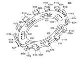
- FIG. 20 shows a perspective view of a configuration example of a resolver according to the second embodiment of the present invention.
- illustration of wiring is omitted.
- a 14-phase salient pole portion having a single-phase excitation and two-phase output type resolver will be described as an example.
- the present invention is not limited to this.
- the resolver 700 in Embodiment 2 is a so-called outer stator type / inner rotor type angle detection device. That is, the edge (circumferential portion) constituting the inner diameter of the annular body (rotor or stator) in plan view is the inner peripheral side (the inner diameter side, the side closer to the annular central portion), and the outer diameter of the annular body is configured. When the edge portion (circumferential portion) is the outer peripheral side (the outer diameter side, the side far from the annular central portion), a magnetic path is formed between the outer peripheral side of the annular rotor and the salient pole portion of the annular stator. In addition, the inner peripheral surface of the salient pole portion of the stator faces the outer peripheral surface of the rotor, and the signal from the detection winding provided in the stator changes according to the rotation angle of the rotor.
- a resolver 700 according to the second embodiment includes a stator (stator) 800 and a rotor (rotor) 900.
- the stator 800 is provided so as to protrude from the outer peripheral side (the side far from the center of the annular flat plate) of a ring-shaped flat plate made of a magnetic material, and then is raised with respect to the flat plate surface.
- each salient pole portion facing the rotor 900 is not a flat surface but the center portion of the annular flat plate. It forms a part of the center arc.
- each salient pole portion is provided with a winding member for excitation and a winding member for detection as a winding core. That is, the salient pole part 810a is provided with a winding member 820a for excitation and detection as a winding magnetic core, and the salient pole part 810b is provided with a winding for excitation and detection as a winding magnetic core. A member 820b is provided, and the salient pole portion 810c is provided with a winding member 820c for excitation and detection as a winding magnetic core, and the salient pole portion 810d is provided with an excitation and detection as a winding magnetic core.
- Winding member 820d is provided, and the salient pole portion 810e is provided with a winding member 820e for excitation and detection as a winding magnetic core.
- the salient pole part 810f is provided with a winding member 820f for excitation and detection as a winding magnetic core
- the salient pole part 810g is provided with a winding for excitation and detection as a winding magnetic core.
- a wire member 820g is provided, the salient pole portion 810h is provided with a winding member 820h for excitation and detection as a winding magnetic core, and the salient pole portion 810j is provided with a winding core for excitation and A winding member 820j for detection is provided, and a winding member 820k for excitation and detection is provided as a winding magnetic core in the salient pole portion 810k.
- the salient pole part 810m is provided with a winding member 820m for excitation and detection as a winding magnetic core, and the salient pole part 810n has a winding for excitation and detection as a winding magnetic core.
- a member 820n is provided, and the salient pole portion 810p is provided with a winding member 820p for excitation and detection as a winding magnetic core, and the salient pole portion 810q is provided as a winding magnetic core with excitation and detection. Winding member 820q is provided.
- the salient pole portions 810a to 810q of the stator 800 are formed in advance on a flat plate and then raised so as to be perpendicular to the flat plate surface by bending press processing (bending processing in a broad sense).
- the stator 800 has a plurality of attachment holes 830 (seven in the second embodiment) that are longer in the circumferential direction than in the radial direction. Accordingly, the resolver 700 is configured such that a fixing member (not shown) can be attached to a given fixing plate (not shown) through these attachment holes 830. Thus, by forming the attachment hole 830 to be long in the circumferential direction of the stator 800, fine adjustment of the fixed position of the resolver 700 with respect to the rotation direction of the rotor 900 can be easily performed.
- the rotor 900 is made of a magnetic material and is provided so as to be rotatable with respect to the stator 800. More specifically, the rotor 900 can rotate with respect to the stator 800 such that the gap permeance between the salient pole portions of the stator 800 and the inner peripheral surface changes due to rotation around the rotation axis of the rotor 900. Is provided.
- the winding directions of the winding members 820a to 820q provided on the salient pole portions 810a to 810q are the same as those in FIGS. 2A and 2B described in the first embodiment. Therefore, detailed description is omitted. That is, in the second embodiment, as shown in FIG. 2A, the winding member for excitation is provided such that the winding directions of the winding members provided in the adjacent salient pole portions are opposite to each other. .
- the winding member for excitation provided in each salient pole part can be a coil winding, for example. An excitation signal is given between the windings R1 and R2 constituting such a winding member for excitation.
- the detection winding member is composed of two sets of winding members in order to obtain a two-phase detection signal.
- the winding member for detection for obtaining the detection signal of the first phase (for example, SIN phase) of the two-phase detection signals is, for example, every other one from the salient pole part 810a to the salient pole part 810p counterclockwise. It is wound around the salient pole part.
- every other winding member for detection for obtaining a detection signal of the second phase (for example, COS phase) of the detection signal of two phases is from the salient pole part 810q to the salient pole part 810n counterclockwise. Is wound around each salient pole part.
- the first phase detection signal is detected as a signal between the windings S1 and S3, and the second phase detection signal is detected as a signal between the windings S2 and S4.
- the winding member for detection provided in each salient pole portion can be, for example, a coil winding.
- the winding direction of the exciting winding member is not limited to the direction shown in FIG.
- the winding direction of the winding member for detection is not limited to the direction shown in FIG.
- Each salient pole portion of the stator 800 is provided with a winding member.
- a magnetic circuit is formed between adjacent salient pole portions via the rotor 900.
- the winding member is provided on each salient pole portion so that the direction of the magnetic flux passing through the adjacent salient pole portions is opposite.
- the waveform of the current generated in can be made sinusoidal.
- the material of the stator 800 made of a magnetic material is SPCC (one steel plate) or carbon for mechanical structure, rather than a laminated electromagnetic steel plate, as in the first embodiment. It is desirable to be S45C (one steel plate) which is steel.
- each salient pole portion has a T-shape, and an excitation winding is provided around the support portion that supports the tip portion of each salient pole portion. It is desirable to provide a wire member and a winding member for detection.
- FIG. 21 shows a top view of the stator 800 in the second embodiment.
- the same parts as those in FIG. 21 are identical to FIG. 21.
- the stator 800 according to the second embodiment has no salient protrusion on the outer diameter side of the stator 800 by raising the salient pole portion with respect to the flat plate surface by bending press processing. That is, the maximum outer diameter of the stator 800 after bending is the outer diameter d10 at each salient pole portion. More specifically, out of the outer diameter of the stator 800, the outer diameter d10 at each salient pole portion is larger than the outer diameter d11 between two adjacent salient pole portions of the outer diameter of the stator 800.
- the magnetic efficiency is improved by the magnetic circuit via the salient pole portion, and the transformation ratio of the resolver 700 is increased. Will be able to.
- the resolver 700 according to the second embodiment that has the above-described configuration and can achieve the above-described effects can be manufactured by the same manufacturing method as that of the first embodiment. Therefore, illustration of the flowchart of the manufacturing method of the resolver 700 in Embodiment 2 is abbreviate
- FIG. 22 is a perspective view of the stator 800 in the second embodiment before bending press processing.
- the same parts as those in FIG. FIG. 23 shows a perspective view of the stator 800 in the second embodiment after bending press processing.
- the same parts as those in FIG. FIG. 24 is a perspective view of the stator 800 in the second embodiment after the winding member attaching step.
- the same parts as those in FIG. 20 or FIG. FIG. 25 is an explanatory diagram of a rotor attachment process according to the second embodiment.
- the shape of the stator 800 is processed in the stator shape processing step (step S10), and then the salient pole portion of the plate-shaped stator 800 is bent in the bending press processing step (bending step).
- a plurality of salient pole portions are raised with respect to the flat plate surface (step S12).
- each salient pole portion of the salient pole portions 810a to 810q raised in step S12 is used as a winding magnetic core, and a winding member is provided outside each salient pole portion (step S14).
- the shape of the stator 800 is formed by forming salient pole portions 810a to 810q and attachment holes 830 at the outer diameter side edge of the flat plate made of the annular magnetic material. At this time, as described in FIG. 5, the stator 800 is formed such that the tip shape of each salient pole portion of the salient pole portions 810a to 810q has a T-shape.
- step S12 As shown in FIG. 23, it is processed so as to raise the plurality of salient pole portions formed in step S10 by bending press processing.
- the salient pole portions 810 a to 810 q are raised so as to be substantially perpendicular to the flat plate surface of the stator 800.
- the stator 800 is formed such that the maximum outer diameter of the stator 800 after bending is the outer diameter of each salient pole portion.
- step S14 on each of the salient pole portions raised in step S12, an excitation winding member and a detection winding are provided around a support portion that supports the tip of each salient pole portion.
- a wire member is provided.
- the exciting winding member is attached to each salient pole so that the winding direction is as shown in FIG. 2 (a), and the detection winding member is in the winding direction as shown in FIG. 2 (b). And attached to each salient pole part.
- the rotor 900 shown in FIG. 25 is formed by press working.
- the rotor 900 is an annular flat plate, but the outer contour line on the outer diameter side is two cycles in a plan view with respect to the circumference of the given radius. It has a shape that changes.
- the surface of the inner peripheral side of each salient pole part raised with respect to the flat plate surface so that the rotor 900 having a shape as shown in FIG.
- the outer peripheral side (outer diameter side) surface of the rotor 900 are provided to face each other (step S16).
- the gap permeance between the outer side of the rotor 900 and the inner peripheral surface of each salient pole portion of the stator 800 changes in the rotor 900 due to rotation around the rotation axis of the rotor 900.
- it is provided to be rotatable with respect to the stator 800.
- the resolver 700 in Embodiment 2 as shown in FIG. 20 is manufactured.
- the resolver 700 with a small number of parts can be manufactured at a low cost by a simple method without reducing the detection accuracy. Moreover, even if it is the same size as Embodiment 1, since the number of salient pole parts can be increased significantly, detection accuracy can be further improved.
- digital data corresponding to the rotation angle can be output based on the two-phase detection signal from the resolver 700.
- the angle detection system to which the resolver 700 according to the second embodiment is applied is the same as that shown in FIG.
- the tip shape of the salient pole portion provided in the stator 800 has been described as having a T-shape, but the present invention is not limited to this.
- the salient pole part of the stator may have a so-called I-shape.
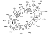
- FIG. 26 shows a perspective view of a configuration example of the stator in the first modification of the second embodiment.
- the same parts as those in FIG. 26 are identical parts as those in FIG. 26.
- the stator 850 includes an annular flat plate made of a magnetic material, and 14 salient pole portions 840a, 840b, 840c, 840d, 840e, 840f raised against the flat plate surface. 840g, 840h, 840j, 840k, 840m, 840n, 840p, 840q. These salient pole portions are formed on the outer (outer diameter side) edge of the annular flat plate, and each salient pole portion has a winding core for excitation and a winding member for detection as a winding core. Is provided. Each salient pole portion has a so-called I-shape, and the width of the tip portion of the salient pole portion is substantially equal to the width of the support portion of the salient pole portion.
- FIG. 27 is a perspective view of a configuration example of a resolver in the first modification of the second embodiment.
- illustration of wiring is omitted.
- FIG. 27 the same parts as those in FIG. 20 or FIG.
- the resolver 880 in the first modification of the second embodiment is a so-called outer stator type / inner rotor type angle detection device.
- the resolver 880 in the first modification of the second embodiment is different from the resolver 700 in the second embodiment in that the tip shape of the salient pole portion of the stator has an I-shape.
- the machining process can be simplified compared to machining the stator of the second embodiment, and the cost can be reduced while reducing the number of components as in the second embodiment. And reliability can be improved. Further, according to the first modification, the magnetic flux passing through the winding core can be increased, so that the detection accuracy can be further improved when the number of salient pole portions is small.
- the resolver 880 in the first modification of the second embodiment can be applied instead of the resolver 100.
- the angle detection device concerning the present invention was explained based on the above-mentioned embodiment, the present invention is not limited to this, and can be implemented in the range which does not deviate from the gist, for example, The following modifications are possible.
- the resolver as the angle detection device has been described as being a one-phase excitation two-phase output type, but the present invention is not limited to this.
- the resolver in each of the above embodiments may be a signal having an excitation signal having a phase other than one phase, or a detection signal having a phase other than two phases.
- the material of the stator made of a magnetic material is ordinary steel or carbon steel for mechanical structure, but the present invention is not limited to this. .
- the stator which concerns on this invention should just be formed with the material which has the reliability with respect to bending press work.
- the shape of the rotor which is an annular flat plate, is the inner diameter side in plan view with respect to the circumference of the given radius with respect to the circumference of the given radius.
- the gap permeance between the salient pole part of the stator and the rotor changes due to the rotation of the rotor by making the outer contour line on the outer diameter side periodically change. It is not limited.
- the stator salient pole part and the rotor The gap permeance may be changed.
- salient pole part 212a ... tip part, 214a ... support part, 220a, 220b, 220c, 2 0d, 220e, 220f, 220g, 220h, 220j, 220k, 820a, 820b, 820c, 820d, 820e, 820f, 820g, 820h, 820j, 820k, 820m, 820n, 820p, 820q ... winding members, 230, 830 ... Mounting holes, 300, 900 ... rotor, 410, 420 ... multilayer substrate, 500 ... R / D converter, 502 ... loop filter, 504 ... bipolar VCO, 506 ...
- up / down counter 508 ... ROM, 510 ... output processing circuit
- 512 signal generation circuit
- 600 angle detection system
- ADD1 adder
- DAC1 digital-analog converter
- MUL1, MUL2, MUL3 multiplier
Landscapes
- Physics & Mathematics (AREA)
- General Physics & Mathematics (AREA)
- Transmission And Conversion Of Sensor Element Output (AREA)
Priority Applications (3)
| Application Number | Priority Date | Filing Date | Title |
|---|---|---|---|
| US13/000,661 US8674687B2 (en) | 2008-06-24 | 2009-06-09 | Angle detection device and method of manufacturing the same |
| JP2010517858A JP5002834B2 (ja) | 2008-06-24 | 2009-06-09 | 角度検出装置及びその製造方法 |
| EP20090770017 EP2293022A4 (de) | 2008-06-24 | 2009-06-09 | Winkeldetektor und herstellungsverfahren dafür |
Applications Claiming Priority (2)
| Application Number | Priority Date | Filing Date | Title |
|---|---|---|---|
| JP2008164968 | 2008-06-24 | ||
| JP2008-164968 | 2008-06-24 |
Publications (1)
| Publication Number | Publication Date |
|---|---|
| WO2009157307A1 true WO2009157307A1 (ja) | 2009-12-30 |
Family
ID=41444376
Family Applications (1)
| Application Number | Title | Priority Date | Filing Date |
|---|---|---|---|
| PCT/JP2009/060564 Ceased WO2009157307A1 (ja) | 2008-06-24 | 2009-06-09 | 角度検出装置及びその製造方法 |
Country Status (4)
| Country | Link |
|---|---|
| US (1) | US8674687B2 (de) |
| EP (1) | EP2293022A4 (de) |
| JP (1) | JP5002834B2 (de) |
| WO (1) | WO2009157307A1 (de) |
Cited By (1)
| Publication number | Priority date | Publication date | Assignee | Title |
|---|---|---|---|---|
| WO2024224658A1 (ja) * | 2023-04-28 | 2024-10-31 | ミネベアミツミ株式会社 | 角度センサ及び回転機器 |
Families Citing this family (7)
| Publication number | Priority date | Publication date | Assignee | Title |
|---|---|---|---|---|
| DE102009061032A1 (de) * | 2009-05-15 | 2010-11-18 | Tyco Electronics Belgium Ec Bvba | Magnetoelektronischer Winkelsensor, insbesondere Reluktanzresolver |
| JP2014150703A (ja) * | 2013-02-04 | 2014-08-21 | Tamagawa Seiki Co Ltd | レゾルバステータ構造 |
| FR3003027A1 (fr) | 2013-03-05 | 2014-09-12 | Precilec | Capteur angulaire inductif |
| US10823786B2 (en) | 2017-07-28 | 2020-11-03 | Northstar Battery Company, Llc | Battery with internal monitoring system |
| JP6556218B2 (ja) * | 2017-12-22 | 2019-08-07 | 本田技研工業株式会社 | レゾルバロータ及びこれを備えた回転電機 |
| WO2021195118A1 (en) | 2020-03-23 | 2021-09-30 | Moog Inc. | Variable reluctance resolver using surface mounted inductors and/or transformers |
| CN212785100U (zh) * | 2020-09-08 | 2021-03-23 | 苏州元联科技创业园管理有限公司 | 一种铁芯片的折弯工装 |
Citations (6)
| Publication number | Priority date | Publication date | Assignee | Title |
|---|---|---|---|---|
| JPH0833299A (ja) * | 1994-07-11 | 1996-02-02 | Fujitsu Ltd | モータ及びこれを有するディスク装置 |
| JPH0951640A (ja) * | 1995-08-04 | 1997-02-18 | Seiko Epson Corp | モータのヨーク構造 |
| JP2000292119A (ja) | 1999-04-01 | 2000-10-20 | Tamagawa Seiki Co Ltd | 角度検出装置 |
| JP2000292120A (ja) | 1999-04-01 | 2000-10-20 | Tamagawa Seiki Co Ltd | 角度検出装置 |
| JP2001352734A (ja) * | 2000-06-09 | 2001-12-21 | Tamagawa Seiki Co Ltd | 角度検出装置 |
| JP2004205345A (ja) * | 2002-12-25 | 2004-07-22 | Tamagawa Seiki Co Ltd | レゾルバの補正方法 |
Family Cites Families (6)
| Publication number | Priority date | Publication date | Assignee | Title |
|---|---|---|---|---|
| US3059131A (en) * | 1961-05-10 | 1962-10-16 | Cons Electronies Ind Corp | Synchronous motors |
| JP2698013B2 (ja) * | 1993-01-19 | 1998-01-19 | 彰 石崎 | 位置検出装置 |
| US6137204A (en) * | 1998-05-22 | 2000-10-24 | Nsk Ltd. | VR-type resolver |
| JP4602749B2 (ja) * | 2004-12-10 | 2010-12-22 | ミネベア株式会社 | 扁平型レゾルバ |
| JP4236056B2 (ja) * | 2006-02-08 | 2009-03-11 | 三菱電機株式会社 | 磁石発電機 |
| US8669760B2 (en) * | 2008-05-15 | 2014-03-11 | Tamagawa Seiki Co., Ltd. | Angle detection system and method of manufacturing the same |
-
2009
- 2009-06-09 EP EP20090770017 patent/EP2293022A4/de not_active Withdrawn
- 2009-06-09 US US13/000,661 patent/US8674687B2/en not_active Expired - Fee Related
- 2009-06-09 WO PCT/JP2009/060564 patent/WO2009157307A1/ja not_active Ceased
- 2009-06-09 JP JP2010517858A patent/JP5002834B2/ja not_active Expired - Fee Related
Patent Citations (6)
| Publication number | Priority date | Publication date | Assignee | Title |
|---|---|---|---|---|
| JPH0833299A (ja) * | 1994-07-11 | 1996-02-02 | Fujitsu Ltd | モータ及びこれを有するディスク装置 |
| JPH0951640A (ja) * | 1995-08-04 | 1997-02-18 | Seiko Epson Corp | モータのヨーク構造 |
| JP2000292119A (ja) | 1999-04-01 | 2000-10-20 | Tamagawa Seiki Co Ltd | 角度検出装置 |
| JP2000292120A (ja) | 1999-04-01 | 2000-10-20 | Tamagawa Seiki Co Ltd | 角度検出装置 |
| JP2001352734A (ja) * | 2000-06-09 | 2001-12-21 | Tamagawa Seiki Co Ltd | 角度検出装置 |
| JP2004205345A (ja) * | 2002-12-25 | 2004-07-22 | Tamagawa Seiki Co Ltd | レゾルバの補正方法 |
Non-Patent Citations (1)
| Title |
|---|
| See also references of EP2293022A4 |
Cited By (1)
| Publication number | Priority date | Publication date | Assignee | Title |
|---|---|---|---|---|
| WO2024224658A1 (ja) * | 2023-04-28 | 2024-10-31 | ミネベアミツミ株式会社 | 角度センサ及び回転機器 |
Also Published As
| Publication number | Publication date |
|---|---|
| US20110133965A1 (en) | 2011-06-09 |
| EP2293022A4 (de) | 2014-01-15 |
| US8674687B2 (en) | 2014-03-18 |
| JPWO2009157307A1 (ja) | 2011-12-08 |
| JP5002834B2 (ja) | 2012-08-15 |
| EP2293022A1 (de) | 2011-03-09 |
Similar Documents
| Publication | Publication Date | Title |
|---|---|---|
| JP5083782B2 (ja) | 角度検出装置及びその製造方法 | |
| JP5002834B2 (ja) | 角度検出装置及びその製造方法 | |
| JP5182752B2 (ja) | 角度検出装置及びその製造方法 | |
| US20120274185A1 (en) | Motor rotor and motor | |
| JPWO2014200105A1 (ja) | 誘導型位置検出装置 | |
| EP2853861B1 (de) | Positionserkennungsvorrichtung | |
| US10655987B2 (en) | Resolver | |
| JP5098087B2 (ja) | 回転角度検出装置 | |
| JP7270903B2 (ja) | 平板型エンコーダ | |
| JP6867386B2 (ja) | レゾルバ | |
| JP2012018086A (ja) | 回転位置センサ | |
| JP2009270914A (ja) | レゾルバ及び角度検出装置 | |
| JP3429464B2 (ja) | バリアブルリラクタンス型角度検出器 | |
| CN115276361B (zh) | 一种磁阻式旋转变压器的绕线方法 | |
| EP4256276B1 (de) | Positionssensor mit variabler reluktanz | |
| JP7527603B2 (ja) | 角度検出器 | |
| JP4701347B2 (ja) | 回転検出器およびスロット面被覆構造 | |
| JP2011220851A (ja) | 回転角センサ | |
| JPH0716104U (ja) | 磁気レゾルバ | |
| JP2006138738A (ja) | 磁気式エンコーダ装置 | |
| KR20170056485A (ko) | 레졸버 | |
| JP2015094720A (ja) | 位置検出装置 |
Legal Events
| Date | Code | Title | Description |
|---|---|---|---|
| 121 | Ep: the epo has been informed by wipo that ep was designated in this application |
Ref document number: 09770017 Country of ref document: EP Kind code of ref document: A1 |
|
| WWE | Wipo information: entry into national phase |
Ref document number: 2010517858 Country of ref document: JP |
|
| NENP | Non-entry into the national phase |
Ref country code: DE |
|
| WWE | Wipo information: entry into national phase |
Ref document number: 2009770017 Country of ref document: EP |
|
| WWE | Wipo information: entry into national phase |
Ref document number: 13000661 Country of ref document: US |