WO2010001644A1 - 分注装置 - Google Patents
分注装置 Download PDFInfo
- Publication number
- WO2010001644A1 WO2010001644A1 PCT/JP2009/055505 JP2009055505W WO2010001644A1 WO 2010001644 A1 WO2010001644 A1 WO 2010001644A1 JP 2009055505 W JP2009055505 W JP 2009055505W WO 2010001644 A1 WO2010001644 A1 WO 2010001644A1
- Authority
- WO
- WIPO (PCT)
- Prior art keywords
- dispensing
- pipe
- bubbles
- negative pressure
- unit
- Prior art date
- Legal status (The legal status is an assumption and is not a legal conclusion. Google has not performed a legal analysis and makes no representation as to the accuracy of the status listed.)
- Ceased
Links
Images




Classifications
-
- G—PHYSICS
- G01—MEASURING; TESTING
- G01N—INVESTIGATING OR ANALYSING MATERIALS BY DETERMINING THEIR CHEMICAL OR PHYSICAL PROPERTIES
- G01N35/00—Automatic analysis not limited to methods or materials provided for in any single one of groups G01N1/00 - G01N33/00; Handling materials therefor
- G01N35/10—Devices for transferring samples or any liquids to, in, or from, the analysis apparatus, e.g. suction devices, injection devices
- G01N35/1009—Characterised by arrangements for controlling the aspiration or dispense of liquids
-
- G—PHYSICS
- G01—MEASURING; TESTING
- G01N—INVESTIGATING OR ANALYSING MATERIALS BY DETERMINING THEIR CHEMICAL OR PHYSICAL PROPERTIES
- G01N35/00—Automatic analysis not limited to methods or materials provided for in any single one of groups G01N1/00 - G01N33/00; Handling materials therefor
- G01N35/10—Devices for transferring samples or any liquids to, in, or from, the analysis apparatus, e.g. suction devices, injection devices
- G01N35/1009—Characterised by arrangements for controlling the aspiration or dispense of liquids
- G01N35/1016—Control of the volume dispensed or introduced
- G01N2035/1018—Detecting inhomogeneities, e.g. foam, bubbles, clots
-
- G—PHYSICS
- G01—MEASURING; TESTING
- G01N—INVESTIGATING OR ANALYSING MATERIALS BY DETERMINING THEIR CHEMICAL OR PHYSICAL PROPERTIES
- G01N35/00—Automatic analysis not limited to methods or materials provided for in any single one of groups G01N1/00 - G01N33/00; Handling materials therefor
- G01N35/10—Devices for transferring samples or any liquids to, in, or from, the analysis apparatus, e.g. suction devices, injection devices
- G01N35/1009—Characterised by arrangements for controlling the aspiration or dispense of liquids
- G01N35/1016—Control of the volume dispensed or introduced
-
- G—PHYSICS
- G01—MEASURING; TESTING
- G01N—INVESTIGATING OR ANALYSING MATERIALS BY DETERMINING THEIR CHEMICAL OR PHYSICAL PROPERTIES
- G01N35/00—Automatic analysis not limited to methods or materials provided for in any single one of groups G01N1/00 - G01N33/00; Handling materials therefor
- G01N35/10—Devices for transferring samples or any liquids to, in, or from, the analysis apparatus, e.g. suction devices, injection devices
- G01N35/1095—Devices for transferring samples or any liquids to, in, or from, the analysis apparatus, e.g. suction devices, injection devices for supplying the samples to flow-through analysers
- G01N35/1097—Devices for transferring samples or any liquids to, in, or from, the analysis apparatus, e.g. suction devices, injection devices for supplying the samples to flow-through analysers characterised by the valves
-
- Y—GENERAL TAGGING OF NEW TECHNOLOGICAL DEVELOPMENTS; GENERAL TAGGING OF CROSS-SECTIONAL TECHNOLOGIES SPANNING OVER SEVERAL SECTIONS OF THE IPC; TECHNICAL SUBJECTS COVERED BY FORMER USPC CROSS-REFERENCE ART COLLECTIONS [XRACs] AND DIGESTS
- Y10—TECHNICAL SUBJECTS COVERED BY FORMER USPC
- Y10T—TECHNICAL SUBJECTS COVERED BY FORMER US CLASSIFICATION
- Y10T436/00—Chemistry: analytical and immunological testing
- Y10T436/11—Automated chemical analysis
- Y10T436/110833—Utilizing a moving indicator strip or tape
-
- Y—GENERAL TAGGING OF NEW TECHNOLOGICAL DEVELOPMENTS; GENERAL TAGGING OF CROSS-SECTIONAL TECHNOLOGIES SPANNING OVER SEVERAL SECTIONS OF THE IPC; TECHNICAL SUBJECTS COVERED BY FORMER USPC CROSS-REFERENCE ART COLLECTIONS [XRACs] AND DIGESTS
- Y10—TECHNICAL SUBJECTS COVERED BY FORMER USPC
- Y10T—TECHNICAL SUBJECTS COVERED BY FORMER US CLASSIFICATION
- Y10T436/00—Chemistry: analytical and immunological testing
- Y10T436/12—Condition responsive control
-
- Y—GENERAL TAGGING OF NEW TECHNOLOGICAL DEVELOPMENTS; GENERAL TAGGING OF CROSS-SECTIONAL TECHNOLOGIES SPANNING OVER SEVERAL SECTIONS OF THE IPC; TECHNICAL SUBJECTS COVERED BY FORMER USPC CROSS-REFERENCE ART COLLECTIONS [XRACs] AND DIGESTS
- Y10—TECHNICAL SUBJECTS COVERED BY FORMER USPC
- Y10T—TECHNICAL SUBJECTS COVERED BY FORMER US CLASSIFICATION
- Y10T436/00—Chemistry: analytical and immunological testing
- Y10T436/25—Chemistry: analytical and immunological testing including sample preparation
- Y10T436/2575—Volumetric liquid transfer
Definitions
- the present invention relates to a dispensing apparatus for dispensing a liquid sample containing a specimen or a reagent.
- a dispensing device used when dispensing a liquid sample containing a specimen or a reagent is connected to the pipe by operating a dispensing pump, for example, by sucking or discharging the liquid in the pipe.
- the liquid sample is sucked from the dispensing nozzle and dispensed by discharging the sucked liquid sample to a predetermined position.
- Patent Document 1 A dispensing device that removes bubbles adhering to the inside of a cylinder and the surface of a plunger is known (Patent Document 1).
- the present invention has been made in view of the above, and an object of the present invention is to provide a dispensing device that can reliably remove bubbles.
- the dispensing device of the present invention is configured such that a dispensing pump is connected to a pipe connecting between a dispensing nozzle and a water supply pump, and the inside of the pipe is connected by the water supply pump.
- Deaerated water is supplied to fill the vicinity of the tip of the dispensing nozzle, a water supply valve provided in the vicinity of the dispensing pump is closed to form a deaerated water space where the tip of the dispensing nozzle is opened,
- the negative pressure state is maintained by being connected to the deaerated water space via a switching valve.
- a negative pressure means is provided, and when the bubbles in the deaerated water space are removed, the switching valve is opened to bring the deaerated water space into a negative pressure state.
- the dispensing device is characterized in that, in the above invention, the water supply valve has a function of the switching valve, and the negative pressure means is connected thereto.
- the dispensing apparatus is characterized in that, in the above-mentioned invention, the negative pressure means fills the deaerated water set in a negative pressure state in advance.
- a dispensing pump is connected to a pipe connecting between the dispensing nozzle and the water supply pump, and degassed water is supplied into the pipe by the water supply pump so that the tip of the dispensing nozzle A deaeration water space that fills up to the vicinity and closes the water supply valve provided in the vicinity of the dispensing pump to open the tip end side of the dispensing nozzle is formed, and the formed deaerated water space is connected via a switching valve.
- a negative pressure means that maintains a negative pressure state is provided to remove bubbles in the deaerated water space
- the switching valve is opened to bring the deaerated water space into a negative pressure state. The volume is increased, and there is an effect that bubbles in the deaerated water space can be easily removed.
- FIG. 3 is a flowchart illustrating a switching processing procedure by a switching processing unit according to the first embodiment. It is a block diagram which shows the structure of the dispensing apparatus concerning Embodiment 2.
- FIG. 10 is a flowchart illustrating a switching processing procedure by a switching processing unit according to the second embodiment. It is a block diagram which shows the structure of a bubble determination part. It is a wave form diagram which shows the pressure waveform of the deaeration water in the piping detected by the pressure sensor. It is the figure which expanded typically the pressure waveform when the bubble in deaeration water in piping does not exist.
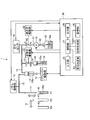
- FIG. 1 is a block diagram showing the configuration of the dispensing apparatus according to the first embodiment of the present invention.
- the dispensing apparatus 1 in FIG. 1 performs dispensing by, for example, sucking a liquid sample containing a specimen or a reagent and discharging the sucked liquid sample.
- the dispensing device 1 includes a dispensing nozzle 11, a dispensing pump 13, a pressure sensor 16, a water supply valve 17, a water supply pump 19, a negative pressure means 24, and a control mechanism 30.
- the dispensing nozzle 11 is made of a rod-like tube made of stainless steel or the like, and is moved in the horizontal direction indicated by the arrow X and the vertical direction indicated by the arrow Y by the nozzle driving unit 12.
- a sample container 40 containing the sample 40a, a reaction container 41 that discharges the sample 40a, and a cleaning container 42 that discharges the deaerated water Wa are arranged. .
- the dispensing pump 13 is realized by a syringe pump, and the plunger driving unit 14 performs a suction / discharge operation of the plunger 13a. Moreover, the plunger drive part 14 is controlled based on the information from the control part 31, and restrict
- the dispensing pump 13 is connected to the dispensing nozzle 11 and the water supply valve 17 by a pipe 15.
- the pressure sensor 16 detects the pressure in the pipe 15 and outputs it to the control unit 31 as a pressure signal.
- the water supply valve 17 is realized by a three-way valve and is connected to the pipe 15 and to the pipe 21 and the pipe 23, respectively. More specifically, the water supply valve 17 has an A end connected to the pipe 15, a B end connected to the pipe 21, and a C end connected to the pipe 23, and each end is opened and closed by the water supply valve driving unit 18.
- the water supply pump 19 sucks up the deaerated water Wa stored in the tank 20 and supplies the deaerated water Wa into the pipe 15 through a water supply valve 17 provided between the dispensing pump 13 and the water supply pump 19.
- a pipe 22 is connected to the water supply pump 19, and the other end of the pipe 22 is connected to a tank 20 that stores deaerated water Wa.
- the deaerated water Wa is an incompressible fluid such as deaerated ion exchange water or distilled water.
- the negative pressure means 24 is realized by a syringe pump, and makes the pressure applied to the deaerated water Wa filled in the pipe 15 into a negative pressure state.
- the negative pressure means 24 is realized by a spacer in a state where the piping 23 is previously filled with the deaerated water Wa and the suction operation of the plunger 24a of the negative pressure means 24 is completed with respect to the filled deaerated water Wa.
- a plunger 24a is prevented from moving by using a fastener 25. By this fastener 25, the deaerated water Wa in the pipe 23 is set to a negative pressure state.
- the control mechanism 30 includes a control unit 31, an input unit 32, a bubble determination unit 33, a switching processing unit 34, a storage unit 35, and an output unit 36.
- the nozzle drive unit 12, the plunger drive unit 14, the pressure sensor 16, the water supply valve drive unit 18, the water supply pump 19, and each of these units included in the control mechanism 30 are connected to the control unit 31.
- the control unit 31 is realized by a CPU, and controls processing and operation of each unit of the dispensing device 1.
- the control unit 31 performs predetermined input / output control on information input to each of these components, and performs predetermined information processing on this information.
- the input unit 32 is realized by a keyboard, a mouse, a touch panel having an input / output function, and the like, and acquires instruction information and the like necessary for dispensing a sample from the outside.
- the input unit 32 acquires and transmits instruction information to the control unit 31 via a communication network (not shown).
- the bubble determination unit 33 detects the pressure in the pipe 15 based on the pressure signal output from the pressure sensor 16, and determines the presence or absence of bubbles in the pipe 15 based on the detected pressure waveform.
- the switching processing unit 34 controls the water supply valve driving unit 18 based on information input to the input unit 32 by the operator via the control unit 31, and performs switching processing of the opening / closing operation of the water supply valve 17 and piping connection. .
- the storage unit 35 is realized by using a hard disk that magnetically stores information and a memory that electrically stores various programs related to the process when the dispensing apparatus 1 executes the process.
- the storage unit 35 may include an auxiliary storage device that can read information recorded on a recording medium such as a CD-ROM, a DVD-ROM, and a PC card.
- the output unit 36 is realized by a display, a printer, a speaker, and the like, and outputs various information.
- the output unit 36 notifies that there are bubbles in the pipe 15.
- the dispensing device 1 configured as described above supplies the deaerated water Wa from the tank 20 by the water supply pump 19 under the control of the control unit 31, and the water supply valve 17 from the dispensing nozzle 11 with the deaerated water Wa. Fill up the space. Thereafter, the water supply valve 17 is closed, and the plunger drive unit 14 discharges the plunger 13a, thereby discharging a predetermined amount of deaerated water Wa to the cleaning container 42 disposed at the position P3. Thereafter, the plunger 13a is sucked and discharged by the plunger drive unit 14, whereby the sample 40a in the sample container 40 arranged at the position P1 is sucked and discharged to the reaction container 41 arranged at the position P2.
- the switching processing unit 34 drives the water supply valve driving unit 18 to open the A end and the C end of the water supply valve 17 and switches the pipe 15 and the pipe 23 to the communication state.
- the deaerated water Wa in the negative pressure state filled in the negative pressure means 24 changes the pressure applied to the deaerated water Wa filled in the pipe 15 to a negative pressure state, and the direction opposite to the dispensing nozzle 11.
- the degassed water Wa is caused to flow backward vigorously.
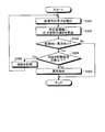
- the switching processing unit 34 drives the water supply valve driving unit 18 based on information input to the input unit 32 by the operator via the control unit 31, and the A end and B of the water supply valve 17. From the state where all the ends and the C end are closed, the A end and the C end are opened, and the piping 15 and the piping 23 to which the negative pressure means 24 is connected are switched (step S101). . Thereby, as described above, the negative pressure state of the negative pressure means 24 acts in the pipe 15.
- the switching processing unit 34 performs switching to close the C end of the water supply valve 17 through the water supply valve driving unit 18 and open the B end so that the pipe 15 and the pipe 21 are in communication with each other (step). S102).
- the feed water pump 19 is driven to supply the deaerated water Wa into the pipe 15, and a discharge process is performed to discharge the air bubbles separated from the dispensing nozzle 11 together with the deaerated water Wa (step S103).
- the switching processing unit 34 acquires the determination result made by the bubble determination unit 33 via the control unit 31 (step S104), and determines whether or not the bubble determination unit 33 determines that there is a bubble in the pipe 15. Determination is made (step S105).
- step S105 determines that bubbles are present in the pipe 15
- the process proceeds to step S101, and the above-described steps S101 to S104 are performed until it is determined that no bubbles are present in the pipe 15.
- the process of switching and discharging is repeated.
- the bubble determination unit 33 determines that there is no bubble in the pipe 15 (step S105: No)
- a negative pressure means 24 that is connected to the pipe 15 via the water supply valve 17 and maintains a negative pressure state is provided, and the negative pressure state of the negative pressure means 24 is applied to the pipe 15.
- Embodiment 1 the negative pressure means 24 is connected to the inside of the pipe 15 via the water supply valve 17, but in Embodiment 2 of the present invention, the negative pressure means 53 is connected via the switching valve 51. Connected to the pipe 15.
- FIG. 3 is a block diagram showing the configuration of the dispensing apparatus according to the second embodiment of the present invention.
- the negative pressure means 53 similar to that in the first embodiment is connected to the pipe 15 via the switching valve 51 between the dispensing pump 13 and the water supply valve 50.
- the negative pressure state of the negative pressure means 53 is applied to the pipe 15.
- the switching valve 51 is realized by an electromagnetic valve and connected to the pipe 15 and to the pipe 52. More specifically, the switching valve 51 has an F end connected to the pipe 15 and a G end connected to the pipe 52.
- the water supply valve 50 is realized by an electromagnetic valve, and has a D end connected to the pipe 15 and an E end connected to the pipe 21.
- the switching processing unit 37 controls the water supply valve driving unit 18 and the switching valve driving unit 55 based on information input to the input unit 32 by the operator via the control unit 31, and the water supply valve 50 and the switching valve 51. Open / close operation and switching of pipe connection.
- the switching processing unit 37 drives the water supply valve driving unit 18 based on the information input to the input unit 32 by the operator via the control unit 31 to close the valve of the water supply valve 50.
- Step S201 the switching valve driving unit 55 is driven, the valve of the switching valve 51 is opened, and the piping 15 and the piping 52 connected to the negative pressure means 53 are switched to communicate with each other (Step S202). .
- Step S202 the negative pressure state of the negative pressure means 53 acts in the pipe 15.
- the switching processing unit 37 drives the switching valve driving unit 55 to close the valve of the switching valve 51 (step S203), drives the water supply valve driving unit 18, opens the valve of the water supply valve 50, and piping 15 And switching the pipe 21 to the communication state (step S204).
- the feed water pump 19 is driven to supply the deaerated water Wa into the pipe 15, and a discharge process is performed to discharge the air bubbles separated from the dispensing nozzle 11 together with the deaerated water Wa (step S205).
- the switching processing unit 37 acquires the determination result made by the bubble determination unit 33 via the control unit 31 (step S206), and determines whether or not the bubble determination unit 33 determines that there is a bubble in the pipe 15. Determination is made (step S207).
- step S207 determines that bubbles are present in the pipe 15
- the process proceeds to step S201, and the above-described steps S201 to S206 are performed until it is determined that no bubbles are present in the pipe 15.
- the process of switching and discharging is repeated.
- the bubble determining unit 33 determines that there is no bubble in the pipe 15 (step S207: No)
- connection position of the negative pressure means 53 can be connected to the pipe 15 via the switching valve 51, the degree of freedom in designing the dispensing device 1 is increased, and the inside of the pipe 15 is increased. Air bubbles that have entered can be reliably removed.
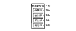
- the bubble determination unit 33 includes a processing unit 33a, a detection unit 33b, a calculation unit 33c, and a determination unit 33d.
- the processing unit 33a amplifies the pressure signal output from the pressure sensor 16, converts the pressure signal into a digital signal based on the amplified pressure signal, and is specifically realized by an A / D converter.
- the detection unit 33b detects the pressure in the pipe 15 from the pressure signal converted into a digital signal by the processing unit 33a.
- the calculating unit 33c calculates the slope of each pressure waveform obtained by dividing the pressure waveform indicated by the pressure signal detected by the detecting unit 33b into a plurality of sections along the time axis.
- the determination unit 33d determines the presence / absence of bubbles in the pipe 15 based on the number of sections in which the inclination calculated by the detection unit 33b is outside the range of the inclination obtained when bubbles are not present.
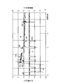
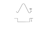
- This pressure waveform W indicates a change in pressure in the pipe 15 when the dispensing apparatus 1 dispenses a sample by an output voltage of the pressure sensor 16.
- the horizontal axis represents time (seconds)
- the left vertical axis represents the output voltage (V) of the pressure signal output from the pressure sensor 16
- the right vertical axis represents the plunger drive unit from the control unit 31.
- 14 is a drive voltage (V) of the drive signal S that drives the plunger 13 a in the dispensing pump 13 that is output to 14.
- the pressure waveform W includes a pressure waveform W ⁇ b> 1 when cleaning the inside of the dispensing nozzle 11, a pressure waveform W ⁇ b> 2 when discharging the degassed water Wa, and a predetermined amount of air sucked into the tip of the dispensing nozzle 11.
- Waveform W5 and the pressure waveform W6 when the sample is discharged from the dispensing nozzle 11 sucked into the reaction container 41 are sequentially displayed.
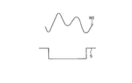
- FIG. 7 is a schematic enlarged view of the pressure waveform W2, and shows a case where bubbles are not present in the degassed water Wa in the pipe 15.
- the waveform forms two large peaks. It has become.
- the pressure waveform W2 forms only one large peak as shown in FIG. Pressure waveform W21.
- the pressure waveform W21 shown in the figure is a case where the amount of bubbles present in the deaerated water Wa is large, and approaches the pressure waveform W2 shown in FIG. 7 as the amount of bubbles decreases.
- the section of the pressure waveform W2 is divided into a plurality of sections A1 to A8 on the time axis, and the pressure waveform W2 when no bubbles exist in each section A1 to A8.
- the reference slopes K1 to K8 are compared with the slopes of the sections of the pressure waveform detected by the pressure sensor 16, and the slopes of the sections are sections of the sections where the reference slopes K1 to K8 exceed the predetermined slope range. The number is counted, and when the counted value is 1 or more, it is determined that bubbles are present in the pipe 15.
- sections A1 to A8 divided by predetermined sampling times t1 to t9 are set corresponding to the pressure waveform W2 in which no bubbles exist, and correspond to the pressure waveform W2 in which no bubbles exist.
- the reference slopes K1 to K8 of the sections A1 to A8 are set in advance.
- the sampling times t1 to t9 are preferably associated with, for example, the maximum point and the minimum point of the pressure waveform W2.
- the pressure signal obtained by the pressure sensor 16 is converted into a digital pressure voltage value by the processing unit 33a, the detection unit 33b detects the pressure voltage values C1 to C9 at the respective sampling times t1 to t9, and the calculation unit 33c
- the slopes KK1 to KK8 of the sections A1 to A8 are calculated.
- the determination unit 33d subtracts the reference inclinations K1 to K8 from the inclinations KK1 to KK8. When the subtraction result is within the predetermined absolute value range, the determination unit 33d determines “ ⁇ ” and out of the predetermined absolute value range. In some cases, “x” is determined, and when “x” is 1 or more, it is determined that bubbles are present in the pipe 15. For example, in FIG. 9, it is determined that all the sections A1 to A8 are “ ⁇ ”, and it is determined that bubbles do not exist in the pipe 15. On the other hand, in FIG. 10, since the sections A3 to A6 are determined as “x” and the determination of “x” is 1 or more, it is determined that bubbles are present in the pipe 15.
- the dispensing device 1 drives the dispensing pump 13 under the control of the control unit 31 during the check before the dispensing start at the time of starting up the analyzer, and the amount in which the internal cleaning has been completed.
- the deaerated water Wa is discharged from the injection nozzle 11 to the cleaning container 42 at the position P3.
- the processing unit 33a converts the pressure waveform detected by the pressure sensor 16 at this time into a digital signal, and the converted digital signal is converted into the digital signal.
- the detection unit 33b detects a pressure waveform (step S301).
- the calculation unit 33c calculates the gradient for each of the sections A1 to A8 based on the pressure waveform detected by the detection unit 33b (step S302). Thereafter, the determination unit 33d compares the slopes KK1 to KK8 calculated for each of the sections A1 to A8 with the reference slopes K1 to K8 obtained when there are no bubbles, and the slopes KK1 to KK8 are obtained in advance.
- the presence / absence of bubbles in the pipe 15 is determined based on the number of sections outside the predetermined inclination range from the obtained reference inclinations K1 to K8 (step S303). Specifically, when the number of sections outside the predetermined inclination range is 1 or more, it is determined that bubbles are present in the pipe 15.
- step S303 When it is determined that no bubble is present (step S303: No), this process ends.
- the determination unit 33d may perform an output such as a display indicating that there are no bubbles in the pipe 15 via the control unit 31.
- the dispensing apparatus 1 starts dispensing a liquid sample containing a specimen or a reagent.
- step S303: Yes the determination unit 33d determines whether or not the number of bubbles removed is equal to or less than the set number (step S304). If the number of bubbles removed is greater than or equal to the set number of times (step S304: No), this is a case where air bubbles are mixed in the pipe 15 in spite of the bubble removal operation. Notification is made (step S305), and the determination unit 33d outputs, through the control unit 31, a display or the like indicating that there is a bubble in the pipe 15 on the output unit 36.
- step S304 when the number of bubble removal is less than or equal to the predetermined number (step S304: Yes), the bubble removal process is executed (step S306).
- This defoaming process is executed by outputting a control signal to the water supply valve drive unit 18 to open the valve and driving the water supply pump 19 to supply the deaerated water Wa in the tank 20 into the pipe 15.
- the determination unit 33d returns to step S301, and repeats the bubble presence / absence determination process in the pipe 15 described above.
- the bubble determination unit 33 since the pressure in the pipe 15 may be detected by the pressure sensor 16, the presence / absence determination of bubbles in the pipe 15 can be easily determined before dispensing. As a result, it is possible to shorten the time for performing re-examination and the like due to dispensing with low dispensing accuracy, and shorten analysis time.
- the bubble determination unit 33 determines that bubbles are present in the pipe 15 when the determination of “x” is 1 or more.
- the present invention is not limited to this, and the pressure waveform when bubbles are present is determined. Depending on the difference between the pressure waveform in the absence of bubbles and the pressure waveform, the determination number of “x” may be varied.
- a predetermined inclination range is set for the determination of “ ⁇ ” or “ ⁇ ”.
- the inclination of each section A1 to A8 is positive or negative. The determination may be made depending on whether or not. For example, when the reference slope K1 of the section A1 is “positive”, when the slope KK1 is “positive”, “ ⁇ ” is determined, and when the slope KK1 is “negative”, “ ⁇ ” Make a decision. This simplifies the determination process by the determination unit 33d.
- the sections A1 to A8 have the same time width.
- the present invention is not limited to this, and the time width of each section A1 to A8 may be varied according to the pressure waveform in which no bubbles are present. .
- the presence / absence determination of bubbles is performed based on the pressure waveform W2 at the time of discharging the deaerated water Wa.
- the present invention is not limited to this, and other pressure waveforms generated in the pipe 15 are used. Originally, the presence / absence determination of bubbles may be performed.
- Embodiment 1 and 2 mentioned above after the negative pressure means 24 or the negative pressure means 53 makes the pressure added to the deaeration water Wa in the piping 15 into a negative pressure state, the operator 25 or 25 It is preferable to remove 54 and move the plunger 24a or the plunger 53a to perform the intake / exhaust operation of the deaerated water Wa. By performing this intake / exhaust operation, the deaerated water Wa moves in the pipe 15, so that the bubbles that have adhered to the pipe 15 and the dispensing pump 13 and have increased in volume are surely separated into the deaerated water Wa. Can be made.
- the plunger 13a is preferably fixed. By fixing the plunger 13a, the negative pressure state in the pipe 15 and the dispensing pump 13 can be ensured.
- Embodiments 1 and 2 described above when dispensing is resumed after stopping the dispensing operation for a long time, air bubbles in the piping are caused by environmental temperature, atmospheric pressure, minor leaks, and the like. Therefore, it is preferable to perform the bubble removal process described above when dispensing is resumed.
- the dispensing device according to the present invention is useful for reliably removing bubbles.
Landscapes
- Physics & Mathematics (AREA)
- Health & Medical Sciences (AREA)
- Life Sciences & Earth Sciences (AREA)
- Chemical & Material Sciences (AREA)
- Analytical Chemistry (AREA)
- Biochemistry (AREA)
- General Health & Medical Sciences (AREA)
- General Physics & Mathematics (AREA)
- Immunology (AREA)
- Pathology (AREA)
- Automatic Analysis And Handling Materials Therefor (AREA)
Abstract
Description
11 分注ノズル
12 ノズル駆動部
13 分注ポンプ
13a,24a,53a プランジャ
14 プランジャ駆動部
15,21,22,23,52 配管
16 圧力センサ
17,50 給水弁
19 給水ポンプ
20 タンク
24,53 負圧手段
25,54 留具
30 制御機構
31 制御部
32 入力部
33 気泡判定部
33a 処理部
33b 検出部
33c 算出部
33d 判定部
34,37 切替処理部
35 記憶部
36 出力部
40 検体容器
40a 検体
41 反応容器
42 洗浄容器
55 切替弁駆動部
Wa 脱気水
Claims (3)
- 分注ノズルと給水ポンプとの間を接続する配管に分注ポンプが接続され、該給水ポンプによって前記配管内に脱気水を供給して前記分注ノズル先端近傍まで満たし、前記分注ポンプの近傍に設けられた給水弁を閉じて分注ノズル先端側が開放された脱気水空間を形成し、この脱気水空間に対して前記分注ポンプを動作させることによって前記分注ノズルによる吸排動作を行わせる分注装置において、
切替弁を介して前記脱気水空間に接続され、負圧状態を維持した負圧手段を備え、前記脱気水空間内の気泡を除去する場合、前記切替弁を開にして前記脱気水空間を負圧状態にすることを特徴とする分注装置。 - 前記給水弁は、前記切替弁の機能を有し、前記負圧手段が接続されることを特徴とする請求項1に記載の分注装置。
- 前記負圧手段は、予め負圧状態に設定した前記脱気水を満たしておくことを特徴とする請求項1または2に記載の分注装置。
Priority Applications (4)
| Application Number | Priority Date | Filing Date | Title |
|---|---|---|---|
| US13/001,776 US8449840B2 (en) | 2008-07-02 | 2009-03-19 | Dispensing device |
| CN200980125941.5A CN102084257B (zh) | 2008-07-02 | 2009-03-19 | 分配装置 |
| EP09773222.6A EP2295987B1 (en) | 2008-07-02 | 2009-03-19 | Dispensing device |
| ES09773222.6T ES2608063T3 (es) | 2008-07-02 | 2009-03-19 | Dispositivo dispensador |
Applications Claiming Priority (2)
| Application Number | Priority Date | Filing Date | Title |
|---|---|---|---|
| JP2008173724A JP5274124B2 (ja) | 2008-07-02 | 2008-07-02 | 分注装置 |
| JP2008-173724 | 2008-07-02 |
Publications (1)
| Publication Number | Publication Date |
|---|---|
| WO2010001644A1 true WO2010001644A1 (ja) | 2010-01-07 |
Family
ID=41465749
Family Applications (1)
| Application Number | Title | Priority Date | Filing Date |
|---|---|---|---|
| PCT/JP2009/055505 Ceased WO2010001644A1 (ja) | 2008-07-02 | 2009-03-19 | 分注装置 |
Country Status (6)
| Country | Link |
|---|---|
| US (1) | US8449840B2 (ja) |
| EP (1) | EP2295987B1 (ja) |
| JP (1) | JP5274124B2 (ja) |
| CN (1) | CN102084257B (ja) |
| ES (1) | ES2608063T3 (ja) |
| WO (1) | WO2010001644A1 (ja) |
Families Citing this family (9)
| Publication number | Priority date | Publication date | Assignee | Title |
|---|---|---|---|---|
| JP5295069B2 (ja) * | 2009-10-09 | 2013-09-18 | ベックマン コールター, インコーポレイテッド | 分注装置、分析装置、および分注方法 |
| JP5772886B2 (ja) * | 2013-06-26 | 2015-09-02 | 東亜ディーケーケー株式会社 | 分析装置 |
| JP6204104B2 (ja) * | 2013-07-29 | 2017-09-27 | 株式会社堀場製作所 | 液体分析装置 |
| JP6230450B2 (ja) * | 2014-03-10 | 2017-11-15 | 株式会社日立ハイテクノロジーズ | 分注装置及び分注方法 |
| US10023333B2 (en) | 2016-03-07 | 2018-07-17 | The Procter & Gamble Company | Vacuum assisted nozzle and apparatus |
| US20200003728A1 (en) * | 2017-02-17 | 2020-01-02 | Life Technologies Corporation | Automated quality control and spectral error correction for sample analysis instruments |
| JP7231038B2 (ja) * | 2019-07-26 | 2023-03-01 | 株式会社島津製作所 | 細胞回収装置および細胞回収方法 |
| JP7374679B2 (ja) * | 2019-09-11 | 2023-11-07 | キヤノン株式会社 | インプリント装置およびインプリント装置の制御方法 |
| CN114160224B (zh) * | 2021-10-22 | 2022-12-06 | 成都开图医疗系统科技有限公司 | 一种微量加样器及加样方法 |
Citations (4)
| Publication number | Priority date | Publication date | Assignee | Title |
|---|---|---|---|---|
| JPH0434700B2 (ja) * | 1983-09-19 | 1992-06-08 | Hitachi Ltd | |
| JPH10114394A (ja) * | 1996-05-31 | 1998-05-06 | Packard Instr Co Inc | 微量流体処理装置 |
| JP2002286737A (ja) * | 2001-03-28 | 2002-10-03 | Canon Inc | プローブ担体製造方法および装置 |
| JP2006343246A (ja) | 2005-06-09 | 2006-12-21 | Olympus Corp | 分注装置および分析装置 |
Family Cites Families (32)
| Publication number | Priority date | Publication date | Assignee | Title |
|---|---|---|---|---|
| BE791890A (fr) * | 1971-11-26 | 1973-03-16 | Rohe Scientific Corp | Echantillonneur et dilueur |
| US4244919A (en) * | 1979-03-19 | 1981-01-13 | Hyperion Incorporated | Sample diluting apparatus |
| US4277440A (en) * | 1979-07-02 | 1981-07-07 | Eastman Kodak Company | Metering apparatus |
| US4968485A (en) * | 1987-09-25 | 1990-11-06 | Shimadzu Corporation | Arrangements for preparative route leading to water analysis |
| JPH0510959A (ja) * | 1991-07-04 | 1993-01-19 | Sanuki Kogyo Kk | 理化学機械用複液混合送液装置 |
| US6521187B1 (en) | 1996-05-31 | 2003-02-18 | Packard Instrument Company | Dispensing liquid drops onto porous brittle substrates |
| US6203759B1 (en) * | 1996-05-31 | 2001-03-20 | Packard Instrument Company | Microvolume liquid handling system |
| GB9405028D0 (en) * | 1994-03-15 | 1994-04-27 | Counting Tech Ltd | Fluid diluter |
| JPH08178806A (ja) * | 1994-10-28 | 1996-07-12 | Shimadzu Corp | 液体試料注入装置 |
| US6083762A (en) * | 1996-05-31 | 2000-07-04 | Packard Instruments Company | Microvolume liquid handling system |
| US5916524A (en) * | 1997-07-23 | 1999-06-29 | Bio-Dot, Inc. | Dispensing apparatus having improved dynamic range |
| JP3682138B2 (ja) | 1997-02-13 | 2005-08-10 | アロカ株式会社 | 分注装置 |
| US6060320A (en) * | 1997-12-05 | 2000-05-09 | Bayer Corporation | Method of verifying aspirated volume in automatic diagnostic system |
| US20020159919A1 (en) * | 1998-01-09 | 2002-10-31 | Carl Churchill | Method and apparatus for high-speed microfluidic dispensing using text file control |
| US6551557B1 (en) * | 1998-07-07 | 2003-04-22 | Cartesian Technologies, Inc. | Tip design and random access array for microfluidic transfer |
| JP3079429B2 (ja) * | 1999-01-26 | 2000-08-21 | サヌキ工業株式会社 | フローインジェクション分析装置 |
| US20030207464A1 (en) * | 1999-02-19 | 2003-11-06 | Tony Lemmo | Methods for microfluidic aspirating and dispensing |
| JP2000251689A (ja) * | 1999-02-26 | 2000-09-14 | Canon Inc | 電子放出素子の製造方法及びそれを用いた電子源基板、画像形成装置の製造方法及びその製造に用いる液滴付与装置 |
| DE10002475C1 (de) * | 2000-01-21 | 2001-05-31 | Roche Diagnostics Gmbh | Analysegerät zur Analyse von Proben |
| US6706245B2 (en) * | 2000-03-10 | 2004-03-16 | Teledyne Tekmar Company | Three stage needle for use with an autosampler |
| JP2002001092A (ja) * | 2000-06-22 | 2002-01-08 | Shimadzu Corp | 排液装置 |
| US20020142341A1 (en) * | 2001-03-28 | 2002-10-03 | Makoto Kameyama | Method and apparatus for producing probe carrier |
| DE60221984T2 (de) * | 2001-06-13 | 2008-05-15 | Kenneth F. Los Gatos Uffenheimer | Automatisches flüssigkeitsbehandlungssystem und -verfahren |
| US6579724B2 (en) * | 2001-09-13 | 2003-06-17 | First Ten Angstroms | Dispensing method and apparatus for dispensing very small quantities of fluid |
| US7288228B2 (en) * | 2002-02-12 | 2007-10-30 | Gilson, Inc. | Sample injection system |
| JP4248328B2 (ja) | 2002-08-07 | 2009-04-02 | 株式会社日立ハイテクノロジーズ | サンプル分注装置およびそれを用いた自動分析装置 |
| JP2004191256A (ja) * | 2002-12-12 | 2004-07-08 | Kawamura Inst Of Chem Res | マイクロ流体素子への試料導入方法 |
| US7294309B1 (en) * | 2003-05-15 | 2007-11-13 | Takeda San Diego, Inc. | Small volume liquid handling apparatus and method |
| JP2007245038A (ja) * | 2006-03-17 | 2007-09-27 | Ebara Corp | マイクロ流体デバイスにおける気泡除去装置及び方法 |
| JP4753770B2 (ja) * | 2006-04-06 | 2011-08-24 | ベックマン コールター, インコーポレイテッド | 分注装置における配管内の気泡の有無判定方法および分注装置 |
| JP2007278833A (ja) * | 2006-04-06 | 2007-10-25 | Olympus Corp | 分注装置における配管内の気泡の有無判定方法および分注装置 |
| JP2007322318A (ja) * | 2006-06-02 | 2007-12-13 | Olympus Corp | サンプル分注装置 |
-
2008
- 2008-07-02 JP JP2008173724A patent/JP5274124B2/ja not_active Expired - Fee Related
-
2009
- 2009-03-19 WO PCT/JP2009/055505 patent/WO2010001644A1/ja not_active Ceased
- 2009-03-19 EP EP09773222.6A patent/EP2295987B1/en active Active
- 2009-03-19 ES ES09773222.6T patent/ES2608063T3/es active Active
- 2009-03-19 CN CN200980125941.5A patent/CN102084257B/zh active Active
- 2009-03-19 US US13/001,776 patent/US8449840B2/en active Active
Patent Citations (4)
| Publication number | Priority date | Publication date | Assignee | Title |
|---|---|---|---|---|
| JPH0434700B2 (ja) * | 1983-09-19 | 1992-06-08 | Hitachi Ltd | |
| JPH10114394A (ja) * | 1996-05-31 | 1998-05-06 | Packard Instr Co Inc | 微量流体処理装置 |
| JP2002286737A (ja) * | 2001-03-28 | 2002-10-03 | Canon Inc | プローブ担体製造方法および装置 |
| JP2006343246A (ja) | 2005-06-09 | 2006-12-21 | Olympus Corp | 分注装置および分析装置 |
Non-Patent Citations (1)
| Title |
|---|
| See also references of EP2295987A4 |
Also Published As
| Publication number | Publication date |
|---|---|
| EP2295987B1 (en) | 2016-10-05 |
| JP2010014490A (ja) | 2010-01-21 |
| EP2295987A1 (en) | 2011-03-16 |
| US8449840B2 (en) | 2013-05-28 |
| EP2295987A4 (en) | 2013-03-06 |
| JP5274124B2 (ja) | 2013-08-28 |
| US20110171744A1 (en) | 2011-07-14 |
| ES2608063T3 (es) | 2017-04-05 |
| CN102084257B (zh) | 2013-07-31 |
| CN102084257A (zh) | 2011-06-01 |
Similar Documents
| Publication | Publication Date | Title |
|---|---|---|
| JP5274124B2 (ja) | 分注装置 | |
| JP5192264B2 (ja) | 気泡有無判定方法および分注装置 | |
| US7799574B2 (en) | Dispensing apparatus and in-duct bubble presence determining method in the same | |
| JP7269869B2 (ja) | 自動分析装置及び分注方法 | |
| JP2015169623A (ja) | 分注装置及び分注方法 | |
| WO2007142155A1 (ja) | サンプル分注装置 | |
| CN102301242A (zh) | 自动分析装置及检测体处理装置 | |
| JP2007322285A (ja) | 分注装置 | |
| JPH10115623A (ja) | 分注装置及びその制御方法 | |
| JP2007047083A (ja) | 分注装置における配管内の気泡の有無判定方法および分注装置 | |
| WO2021215060A1 (ja) | 自動分析装置、分注装置および分注制御方法 | |
| JP4410506B2 (ja) | 自動分析装置 | |
| JP3779649B2 (ja) | 分注装置 | |
| JP2007278833A (ja) | 分注装置における配管内の気泡の有無判定方法および分注装置 | |
| JP2008076275A (ja) | 分注装置 | |
| JP2007240329A (ja) | 分注装置 | |
| JP2007322318A (ja) | サンプル分注装置 | |
| JP2011007568A (ja) | 自動分析装置 | |
| JP2008246279A (ja) | プローブの洗浄方法およびオートサンプラー | |
| HK40104760A (zh) | 检测流路的方法、检测装置以及计算机可读存储介质 | |
| JP2007322244A (ja) | 分注量検出装置 | |
| JP2725440B2 (ja) | 液体容器の接続切替装置 |
Legal Events
| Date | Code | Title | Description |
|---|---|---|---|
| WWE | Wipo information: entry into national phase |
Ref document number: 200980125941.5 Country of ref document: CN |
|
| 121 | Ep: the epo has been informed by wipo that ep was designated in this application |
Ref document number: 09773222 Country of ref document: EP Kind code of ref document: A1 |
|
| REEP | Request for entry into the european phase |
Ref document number: 2009773222 Country of ref document: EP |
|
| WWE | Wipo information: entry into national phase |
Ref document number: 2009773222 Country of ref document: EP |
|
| NENP | Non-entry into the national phase |
Ref country code: DE |
|
| WWE | Wipo information: entry into national phase |
Ref document number: 13001776 Country of ref document: US |