WO2010001810A1 - 高圧直噴内燃機関用燃料レール及びその製造方法 - Google Patents
高圧直噴内燃機関用燃料レール及びその製造方法 Download PDFInfo
- Publication number
- WO2010001810A1 WO2010001810A1 PCT/JP2009/061635 JP2009061635W WO2010001810A1 WO 2010001810 A1 WO2010001810 A1 WO 2010001810A1 JP 2009061635 W JP2009061635 W JP 2009061635W WO 2010001810 A1 WO2010001810 A1 WO 2010001810A1
- Authority
- WO
- WIPO (PCT)
- Prior art keywords
- internal combustion
- combustion engine
- injection internal
- fuel rail
- fuel
- Prior art date
- Legal status (The legal status is an assumption and is not a legal conclusion. Google has not performed a legal analysis and makes no representation as to the accuracy of the status listed.)
- Ceased
Links
Images


Classifications
-
- F—MECHANICAL ENGINEERING; LIGHTING; HEATING; WEAPONS; BLASTING
- F02—COMBUSTION ENGINES; HOT-GAS OR COMBUSTION-PRODUCT ENGINE PLANTS
- F02M—SUPPLYING COMBUSTION ENGINES IN GENERAL WITH COMBUSTIBLE MIXTURES OR CONSTITUENTS THEREOF
- F02M55/00—Fuel-injection apparatus characterised by their fuel conduits or their venting means; Arrangements of conduits between fuel tank and pump F02M37/00
- F02M55/02—Conduits between injection pumps and injectors, e.g. conduits between pump and common-rail or conduits between common-rail and injectors
- F02M55/025—Common rails
-
- B—PERFORMING OPERATIONS; TRANSPORTING
- B23—MACHINE TOOLS; METAL-WORKING NOT OTHERWISE PROVIDED FOR
- B23K—SOLDERING OR UNSOLDERING; WELDING; CLADDING OR PLATING BY SOLDERING OR WELDING; CUTTING BY APPLYING HEAT LOCALLY, e.g. FLAME CUTTING; WORKING BY LASER BEAM
- B23K1/00—Soldering, e.g. brazing, or unsoldering
- B23K1/0008—Soldering, e.g. brazing, or unsoldering specially adapted for particular articles or work
-
- B—PERFORMING OPERATIONS; TRANSPORTING
- B23—MACHINE TOOLS; METAL-WORKING NOT OTHERWISE PROVIDED FOR
- B23K—SOLDERING OR UNSOLDERING; WELDING; CLADDING OR PLATING BY SOLDERING OR WELDING; CUTTING BY APPLYING HEAT LOCALLY, e.g. FLAME CUTTING; WORKING BY LASER BEAM
- B23K1/00—Soldering, e.g. brazing, or unsoldering
- B23K1/19—Soldering, e.g. brazing, or unsoldering taking account of the properties of the materials to be soldered
-
- B—PERFORMING OPERATIONS; TRANSPORTING
- B23—MACHINE TOOLS; METAL-WORKING NOT OTHERWISE PROVIDED FOR
- B23K—SOLDERING OR UNSOLDERING; WELDING; CLADDING OR PLATING BY SOLDERING OR WELDING; CUTTING BY APPLYING HEAT LOCALLY, e.g. FLAME CUTTING; WORKING BY LASER BEAM
- B23K1/00—Soldering, e.g. brazing, or unsoldering
- B23K1/20—Preliminary treatment of work or areas to be soldered, e.g. in respect of a galvanic coating
-
- F—MECHANICAL ENGINEERING; LIGHTING; HEATING; WEAPONS; BLASTING
- F02—COMBUSTION ENGINES; HOT-GAS OR COMBUSTION-PRODUCT ENGINE PLANTS
- F02M—SUPPLYING COMBUSTION ENGINES IN GENERAL WITH COMBUSTIBLE MIXTURES OR CONSTITUENTS THEREOF
- F02M61/00—Fuel-injectors not provided for in groups F02M39/00 - F02M57/00 or F02M67/00
- F02M61/16—Details not provided for in, or of interest apart from, the apparatus of groups F02M61/02 - F02M61/14
- F02M61/168—Assembling; Disassembling; Manufacturing; Adjusting
-
- F—MECHANICAL ENGINEERING; LIGHTING; HEATING; WEAPONS; BLASTING
- F02—COMBUSTION ENGINES; HOT-GAS OR COMBUSTION-PRODUCT ENGINE PLANTS
- F02M—SUPPLYING COMBUSTION ENGINES IN GENERAL WITH COMBUSTIBLE MIXTURES OR CONSTITUENTS THEREOF
- F02M63/00—Other fuel-injection apparatus having pertinent characteristics not provided for in groups F02M39/00 - F02M57/00 or F02M67/00; Details, component parts, or accessories of fuel-injection apparatus, not provided for in, or of interest apart from, the apparatus of groups F02M39/00 - F02M61/00 or F02M67/00; Combination of fuel pump with other devices, e.g. lubricating oil pump
- F02M63/02—Fuel-injection apparatus having several injectors fed by a common pumping element, or having several pumping elements feeding a common injector; Fuel-injection apparatus having provisions for cutting-out pumps, pumping elements, or injectors; Fuel-injection apparatus having provisions for variably interconnecting pumping elements and injectors alternatively
- F02M63/0225—Fuel-injection apparatus having a common rail feeding several injectors ; Means for varying pressure in common rails; Pumps feeding common rails
- F02M63/0275—Arrangement of common rails
-
- B—PERFORMING OPERATIONS; TRANSPORTING
- B23—MACHINE TOOLS; METAL-WORKING NOT OTHERWISE PROVIDED FOR
- B23K—SOLDERING OR UNSOLDERING; WELDING; CLADDING OR PLATING BY SOLDERING OR WELDING; CUTTING BY APPLYING HEAT LOCALLY, e.g. FLAME CUTTING; WORKING BY LASER BEAM
- B23K2101/00—Articles made by soldering, welding or cutting
- B23K2101/006—Vehicles
-
- B—PERFORMING OPERATIONS; TRANSPORTING
- B23—MACHINE TOOLS; METAL-WORKING NOT OTHERWISE PROVIDED FOR
- B23K—SOLDERING OR UNSOLDERING; WELDING; CLADDING OR PLATING BY SOLDERING OR WELDING; CUTTING BY APPLYING HEAT LOCALLY, e.g. FLAME CUTTING; WORKING BY LASER BEAM
- B23K2101/00—Articles made by soldering, welding or cutting
- B23K2101/04—Tubular or hollow articles
- B23K2101/06—Tubes
-
- B—PERFORMING OPERATIONS; TRANSPORTING
- B23—MACHINE TOOLS; METAL-WORKING NOT OTHERWISE PROVIDED FOR
- B23K—SOLDERING OR UNSOLDERING; WELDING; CLADDING OR PLATING BY SOLDERING OR WELDING; CUTTING BY APPLYING HEAT LOCALLY, e.g. FLAME CUTTING; WORKING BY LASER BEAM
- B23K2103/00—Materials to be soldered, welded or cut
- B23K2103/02—Iron or ferrous alloys
- B23K2103/04—Steel or steel alloys
-
- B—PERFORMING OPERATIONS; TRANSPORTING
- B23—MACHINE TOOLS; METAL-WORKING NOT OTHERWISE PROVIDED FOR
- B23K—SOLDERING OR UNSOLDERING; WELDING; CLADDING OR PLATING BY SOLDERING OR WELDING; CUTTING BY APPLYING HEAT LOCALLY, e.g. FLAME CUTTING; WORKING BY LASER BEAM
- B23K2103/00—Materials to be soldered, welded or cut
- B23K2103/02—Iron or ferrous alloys
- B23K2103/06—Cast-iron alloys
Definitions
- the present invention relates to a fuel rail (delivery pipe) for supplying high-pressure fuel supplied from a fuel pressurizing pump such as an electronic fuel injection type automobile engine through a fuel injector (injection nozzle) that directly injects the fuel into a cylinder of the engine. More specifically, the present invention relates to a fuel rail for a high pressure direct injection internal combustion engine of a compression ignition type or a spark ignition type in a type in which fuel is directly supplied from a rail to an injector, and a manufacturing method thereof.
- Patent Document 2 discloses that after the components such as the main rail, the fuel supply pipe and the socket are brazed, the entire product and In the fuel rail provided with a main pipe and a plurality of branch pipes, a through-hole for receiving each branch pipe is formed on the outer wall of the main pipe in Patent Document 3 in which the inner peripheral surface of the pipe is plated.
- Each through-hole has an annular wall protruding toward the outside and inside of the main pipe, and each branch pipe has a structure fixed to the annular wall.
- Injector Ho A fuel rail having loaders, those connection configuration to each other with a state of inserting the injector holder through-hole provided in the peripheral wall of the main pipe rail, are described, respectively.
- the fuel injector (injection nozzle) connecting portion has an O-ring seal structure.
- machining is required to ensure positional accuracy and assembly accuracy.
- a fuel rail for this type of high pressure direct injection gasoline engine for example, a fuel rail for a direct injection internal combustion engine obtained by machining an aluminum casting or an extrusion mold material (see Patent Document 5), or a component made of stainless steel.
- a fuel rail for a direct injection internal combustion engine assembled by brazing or welding (see Patent Document 6) or the like is known.
- Patent Document 7 a through hole is provided in a peripheral wall portion of a cylindrical container or a peripheral wall portion of a spherical container, and a connecting structure is formed by brazing each other with a branch branch pipe or a branch joint fitting inserted into the through hole.
- Patent Document 8 discloses that a main block rail is formed by brazing a short block having a flow path inside the shaft core and having a boss portion provided with a through hole communicating with the flow path.
- a structure in which a branch branch pipe or a branch joint fitting is connected to the boss portion is disclosed in Patent Document 9 by brazing each other with a branch joint fitting inserted into a through hole provided in a peripheral wall portion of the main rail. Each connected configuration is described.
- the conventional fuel rails for high pressure direct injection internal combustion engines made of aluminum or stainless steel have the following problems.
- Aluminum fuel rails for direct injection internal combustion engines have low material strength and cannot be used for diesel engines with injection pressures of 150 to 250 MPa.
- the rails In order to withstand pressure, the rails must be thick, the layout is poor, and since they are vulnerable to alcohol and corrosive fuels, it is necessary to apply special surface treatments to the contact surfaces with the fuel. There is a problem that the cost is high.
- the fuel rail for direct injection internal combustion engines is close to the line for fixing the injector and the line for fixing the rail, so when assembled by brazing, the injector holder and rail mounting boss The part is disposed offset to the same side with respect to the fuel supply pipe. For this reason, there is a possibility that the rail is thermally deformed by tack welding at the time of rail assembly. Further, since the weight is biased to one side of the rail at the time of brazing, there is a possibility that the rail is also greatly thermally deformed.
- the present invention has been made in view of the above-described problems of the conventional fuel rail for a high-pressure direct-injection internal combustion engine, and particularly has a structure in which an injector holder, a branch nipple, and a fixing bracket are directly attached to the rail body.
- an injector holder, a branch nipple, and a fixing bracket are directly attached to the rail body.
- the position accuracy of the injector holder and branch nipple and the surface roughness of the sealing surface will be achieved by finishing after the brazing.
- a high-quality fuel rail for high-pressure direct-injection internal combustion engines that has excellent sealing performance, excellent contact angle with the mating member of the fixing bracket, and tilt accuracy and surface roughness of the seat surface of the bolt or nut. And it aims at proposing the manufacturing method which can provide the high quality fuel rail at low cost.
- the fuel rail for a high-pressure direct-injection internal combustion engine according to the present invention is for a high-pressure direct-injection internal-combustion engine in which the components of the fuel rail for a direct-injection internal-combustion engine are made of steel or stainless steel and the components are brazed to each other.
- the fuel rail for a high-pressure direct-injection internal combustion engine according to the present invention includes a steel rail or a stainless steel direct-injection internal combustion engine fuel rail injector holder and a fixing bracket that are brazed and joined to the main rail. It is characterized by having a configuration.
- the injector holder and the fixing bracket that form the pair are eccentrically provided on one side with respect to the axis of the main rail.
- the component part of the fuel rail for the direct injection internal combustion engine is made of steel
- at least the contact part of the component part and its brazed joint with the fuel is coated with a plating film.
- the plating film is preferably a chemical nickel plating film.
- at least a contact part of the component with the fuel is coated with a chemical nickel plating film, and an outer surface of the component is coated with a zinc plating film or a zinc-nickel plating film. Is a preferred embodiment.
- a method for manufacturing a fuel rail for a high-pressure direct-injection internal combustion engine includes the steps of brazing steel or stainless steel components of the fuel rail for the direct-injection internal combustion engine to each other, and assembling in the step. And a step of cutting and / or burnishing at least a part or one part of the components of the fuel rail for a high-pressure direct-injection internal combustion engine.
- the component is subjected to a pre-processing before brazing and a finishing process after brazing.
- the method of the present invention is preferably such that the injector holder and the fixing bracket of the steel or stainless steel direct-injection internal combustion engine fuel rail are brazed and joined to the main rail in pairs.
- the injector holder and the fixing bracket forming the pair are provided eccentrically on one side with respect to the axis of the main rail.
- plating is performed on at least the contact part of the component part and its brazed joint with the fuel.
- a preferred embodiment and the plating film is preferably a chemical nickel plating film.
- a chemical nickel plating is first applied to at least a contact portion of the component with the fuel, and then a zinc plating or a zinc-nickel plating is applied to the outer surface of the component. To do.
- a through hole communicating with the flow passage of the rail is provided in advance in the peripheral wall portion of the main rail, or the injector holder is provided in advance.
- a pilot hole may be provided, and the pilot hole may be machined after assembly brazing. Further, it may be machined after assembly brazing without providing a pilot hole in the injector holder.
- the fuel rail for a high-pressure direct-injection internal combustion engine according to the present invention is assembled by brazing because the components brazed to each other are finished by cutting and / or burnishing after brazing. Even with high-strength steel or stainless steel fuel rails, the position accuracy and seal surface roughness of the connecting parts such as the fuel injector (injection nozzle) holder, injector connection branch nipple, and fixing bracket Is sufficiently secured, and the sealing performance of the O-ring seal structure and the inclined surface pressing seal structure is extremely high.
- the position and inclination accuracy of the bolt insertion hole, the contact seat surface with the mating member, Inclination accuracy and surface roughness of the seat surface of the nut can be secured, and the mounting strength to the engine block and the pressing strength to the injector
- the pressure to achieve the excellent effect of the force) and the like to prevent the injector is pressed to fine movement in is improved.
- the component parts of the fuel rail for the high-pressure direct injection internal combustion engine are made of steel
- the component part and its brazed joint part, and further, the contact part of the component part with the fuel may be a chemical nickel plating film or galvanization.
- the present invention has a high reliability that can sufficiently withstand an injection pressure of about 150 to 250 MPa in a compression ignition type engine and an injection pressure of about 10 to 40 MPa in a spark ignition type engine. This greatly contributes to improving the quality and reducing manufacturing costs of fuel rails for high-pressure direct-injection internal combustion engines.
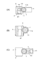
- FIG. 3 is a cross-sectional view of each part of the spark ignition type fuel rail for a high-pressure direct-injection internal combustion engine, wherein (A) is an enlarged cross-sectional view taken along the line aa in FIG. 2, and (B) is an enlarged cross-sectional view taken along the line bb; (C) is an enlarged sectional view taken along the line cc.
- FIG. 5 is an enlarged cross-sectional view taken along the line dd in FIG. 4.
- FIG. 5 is a view corresponding to FIG. 5 showing another embodiment of the manufacturing method shown in FIG. 4.
- FIG. 5 is a view corresponding to FIG. 5 showing another embodiment of the manufacturing method shown in FIG. 4.
- It is a top view which shows the other Example of the fuel rail for high pressure direct injection internal combustion engines of the compression ignition system which concerns on this invention.
- FIG. 9 is an enlarged cross-sectional view taken along line ee in FIG. 8. It is process drawing which shows roughly one Example of the manufacturing method of the fuel rail for compression ignition type high pressure direct injection internal combustion engines which concerns on this invention.
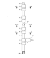
- FIG. 1 is a plan view showing an embodiment of a fuel rail for a spark ignition type high pressure direct injection internal combustion engine according to the present invention
- FIG. 2 is a front view of the fuel rail for a high pressure direct injection internal combustion engine
- FIG. FIG. 3 is a cross-sectional view of each part of a fuel rail for a high-pressure direct-injection internal combustion engine, in which (A) is an enlarged cross-sectional view taken along the line aa in FIG. 2, (B) is an enlarged cross-sectional view taken along the line bb; 4 is an enlarged sectional view on line c, FIG.
- FIG. 4 is a process diagram schematically showing one embodiment of a method of manufacturing a fuel rail for a high pressure direct injection internal combustion engine according to the present invention
- FIG. 5 is an enlarged section on line dd in FIG.
- FIG. 6 is a diagram corresponding to FIG. 5 showing another embodiment of the method of the present invention
- FIG. 7 is a diagram corresponding to FIG. 5 showing another embodiment of the method of the present invention
- FIG. 8 is a diagram of the compression ignition system according to the present invention.
- FIG. 9 is a plan view showing another embodiment of the fuel rail for the high pressure direct injection internal combustion engine
- FIG. 9 is a front view of the fuel rail for the high pressure direct injection internal combustion engine
- 11 is a process diagram schematically showing an embodiment of a manufacturing method of a fuel rail for a high-pressure direct injection internal combustion engine, wherein 1, 11 are main rails, 1-1, 11 -1 is a flow passage, 1-1a and 11-1a are inner peripheral walls, 1-2 and 11-2 are through holes, 2 is an injector holder, 2-1 is a finishing hole, 2-2 is a lower hole, 2 -3 is a horizontal hole, 3 and 13 are fixing brackets, 4 is a pressure sensor boss, 5 is a plug, 6 is an inlet connector, 7 and 17 are injectors, 12 is a branch nipple for injector connection, 14 is a pressure sensor nipple, Reference numeral 15 denotes an inlet nipple, 18 denotes a screw sleeve, and 19 denotes a cap nut.
- injector holders there are four injector holders, and a fuel rail for a high-pressure direct-injection internal combustion engine for a spark ignition system in which the injector holder and the fixing bracket are eccentrically provided on one side from the axis of the main rail, and a branch nipple 4 and the branch nipple is on the axis of the main rail, and the fixing bracket is eccentric to the one side of the axis.
- the main rails 1 and 11 in the present invention are fuel rail bodies for a high-pressure direct injection internal combustion engine, and a fuel introduction pipe (not shown) is connected to one end or a pipe wall surface via an inlet connector 6 and an inlet nipple 15.
- the fuel introduction pipe is connected to a high-pressure fuel pump (not shown) and connected to a fuel tank (not shown) containing a low-pressure fuel pump via a pipe (not shown).
- the fuel is transferred to the fuel introduction pipe through the pipe and the high-pressure fuel pump, flows from the fuel introduction pipe to the main rails 1 and 11 through the inlet connector 6 and the inlet nipple 15, and from the injectors 7 and 17 to the cylinder (see FIG. (Not shown).
- a main rail 1 of a fuel rail for a high pressure direct injection internal combustion engine shown in FIG. 1 is a steel or stainless steel pipe having a pipe diameter of about ⁇ 15 to ⁇ 30 mm and a wall thickness of about 1.5 to 2.5 mm.
- a plurality of steel or stainless steel injector holders 2 that can connect the injectors 7 are provided.
- four injector holders 2 are provided at desired intervals in the case of a four-cylinder engine, and six injector holders 2 are provided in an in-line six-cylinder engine.
- Each injector holder 2 is provided with a fixing bracket 3 made of steel or stainless steel on the main rail 1 in a pair with the holder in order to firmly fix the holder.
- a spark ignition type fuel rail for a high-pressure direct-injection internal combustion engine shown in FIG. 1 is formed on a peripheral wall portion extending in the axial direction of a main rail 1 having a cylindrical inner peripheral wall surface 1-1a having a flow passage 1-1 therein.
- the structure is such that four injector holders 2 are brazed and joined to the drilled through holes 1-2, and a fixing bracket 3 is paired with each injector holder 2 to the main rail 1. Further, a pressure sensor boss 4 is attached to the wall surface of the main rail 1, and a plug 5 and an inlet connector 6 are attached to the end of the pipe by brazing.
- the fuel rail for the high-pressure direct injection internal combustion engine includes all the main rail 1, the injector holder 2, the fixing bracket 3 and the pressure sensor boss 4 which are the components thereof after the brazing. And finished.
- the plating film is preferably a chemical nickel plating film.
- at least a contact portion of the component with the fuel is first subjected to chemical nickel plating, and subsequently, a zinc plating film having a chromate layer or a zinc-nickel plating having a chromate layer is applied to the outer surface of the component. Can do.
- FIG. 3A is a cross-sectional view of a portion of the injector holder 2, and a finishing hole 2-1 is formed in a portion of a through hole 1-2 drilled in a peripheral wall portion extending in the axial direction of the main rail 1.
- An injector holder 2 having a horizontal hole 2-3 formed by cutting is brazed and joined to the main rail 1.
- the finishing hole 2-1 which is a sealing surface with a seal ring (not shown) built in the injector may be further burnished.
- FIG. (B) is a cross-sectional view of a portion of the fixing bracket 3, and the fixing bracket 3 in which the finishing hole 3-1 is provided by drilling is brazed and joined to the main rail 1.
- FIG. 4C is a cross-sectional view of the pressure sensor boss 4, and a finishing hole 4-1 and a communication hole 4-2 are formed in a through hole 1-3 formed in the peripheral wall of the main rail 1.
- the pressure sensor boss 4 provided by cutting with a drill or the like is brazed and joined to the main rail 1 at a predetermined angle.
- the finishing hole 4-1 which is a sealing surface with a seal ring built in a pressure sensor (not shown) may be burnished as necessary.
- the joint surfaces of the injector holder 2, the fixing bracket 3 and the pressure sensor boss 4 with the main rail 1 are recessed in advance with an arc-shaped cross section so as to follow the outer peripheral surface of the main rail 1 ( ⁇ Formed).
- FIGS. 1-10 When manufacturing a fuel rail for a high-pressure direct-injection internal combustion engine, first, a steel or stainless steel tube body having a cylindrical inner peripheral wall surface 1-1a having an internal flow passage 1-1 is provided in advance in the axial direction. Injector holder 2 in which lower holes 2-2 and lateral holes 2-3 are provided in advance in the brazing process for main rail 1 having a plurality of, in this case, four through holes 1-2 formed in the peripheral wall portion. (FIG.
- the fixing bracket 3 previously provided with the lower hole 3-2, and the pressure sensor boss 4 previously provided with the lower hole 4-3 are respectively temporarily attached and brazed.
- four sets of the injector holder 2 and the fixing bracket 3 are prepared in accordance with the number of through holes 1-2 drilled in the peripheral wall portion of the main rail 1, each of which corresponds to four through holes 1-2.
- the injector holder 2 is arranged corresponding to the through hole 1-2, and further, a fixing bracket 3 is arranged in pairs with each injector holder 2, and the injector holder 2, the fixing bracket 3, and the pressure sensor
- Each boss 4 is tack welded.
- the brazing operation is performed in a non-oxidizing atmosphere furnace if it is made of steel, or by a copper brazing material or a nickel brazing material in a hydrogen furnace or a vacuum furnace if it is made of stainless steel.
- the injector holder 2, the fixing bracket 3 and the pressure sensor boss 4 of the fuel rail for the high-pressure direct-injection internal combustion engine assembled in the brazing process are respectively cut by cutting, and if necessary. Finish with a burnishing process.
- the finished hole 2-1 is formed by machining a portion of the prepared lower hole 2-2 by cutting using a drill or a reamer.
- the fixing bracket 3 and the pressure sensor boss 4 are each processed with a drill, an end mill, a reamer, etc. in the finished holes 3-1, 4-1.
- the assembly holder brazing is performed with the injector holder 2 not provided with the lower hole 2-2 but only the horizontal hole 2-3. Then, after finishing in a cutting process, first, the prepared hole is drilled, then reamed, and further processed by a burnishing roll to form the processed hole 2-1. Further, as shown in FIG. 7 showing another embodiment of the method of the present invention, the injector holder 2 is assembled and brazed without providing the pilot holes 2-2 and the lateral holes 2-3, and then finished by a cutting process. The hole 2-1 and the main rail 1 may be cut and burned at the same time, and the finishing hole 2-1 of the injector holder 2 and the flow passage 1-1 of the main rail 1 may be communicated with each other.
- the method for manufacturing a fuel rail for a direct-injection internal combustion engine of the spark ignition method of the present invention after assembling steel or stainless steel components of a fuel rail for a direct-injection internal combustion engine by brazing, By cutting and / or burnishing each component, even if the main rail is thermally deformed during temporary mounting or brazing of each component, a rail correction process or correction process is required.
- the position and inclination accuracy of the fuel injector holder connecting portion and the surface roughness of the seal surface can be sufficiently ensured.
- the fuel rail manufacturing method of the present invention is such that when the main barrel 1, the injector holder 2, the fixing bracket 3, and the pressure sensor boss 4 are made of steel, the component and its brazed joint portion Or at least a portion of the component that is in contact with the fuel is subjected to chemical nickel plating, and further, at least a portion of the component that is in contact with the fuel is subjected to chemical nickel plating, and then the zinc plating having a chromate layer on the outer surface of the component or Similarly, by applying zinc-nickel plating having a chromate layer, heat resistance and corrosion resistance can be further improved.
- the fuel rail for a compression ignition type high pressure direct injection internal combustion engine shown in FIGS. 8 to 10 is a carbon steel having a cylindrical inner wall surface 11-1a having a flow passage 11-1 therein and a tube diameter of about 40 mm or less.
- the shaft core made of four steel materials or stainless steel material is formed in the through hole 11-2 formed in the inner peripheral wall portion extending in the axial direction of the main rail 11 made of a thick steel tube material such as stainless steel, preferably in a flat portion.
- connection end of the injector connecting branch nipple 12 having the flow path 12-1 is inserted deeply and the flow passage side tip of the nipple projects from the rail inner peripheral wall surface 11-1a to the inside of the flow passage 11-1.
- each of the injector connecting branch nipples 12 is provided with a finishing hole 13-1 for inserting a bolt.
- a fixed bracket 13 made of steel or stainless steel is paired and brazed to the main rail 11, and the main rail 1 is connected to a pressure sensor nipple 14 made of steel or stainless steel and an inlet nipple. Each 15 is attached by brazing.
- the compression ignition type direct injection internal combustion engine fuel rail shown in FIGS. 8 to 10 is the same as the spark ignition type high pressure direct injection internal combustion engine fuel rail.
- the connecting branch nipple 12, the fixing bracket 13, the pressure sensor nipple 14 and the inlet nipple 15 and their brazed joints are all spark ignition type high pressure direct injection shown in FIGS.
- the branch nipple 12 is subjected to burnishing if necessary after the sheet surface 12-4 with the injector 17 is cut. Cutting using 3 threaded processing is given.
- the joint surface of the fixing bracket 13 with the main rail 11 is previously recessed with an arcuate cross section ( ⁇ ) so as to follow the outer peripheral surface of the main rail 11. Formed).
- This fuel rail is also used for the spark ignition type high pressure direct injection internal combustion engine. Similar to the method of manufacturing the fuel rail, first, a steel or stainless steel tube having a cylindrical inner peripheral wall surface 11-1a having a flow passage 11-1 inside is formed on a peripheral wall portion extending in the axial direction in advance. In the brazing step, the injector connecting branch nipple 12 provided with the pilot hole 12-2 in advance, and the pilot hole 13- The fixing bracket 13 provided with 2, the pressure sensor nipple 14 and the inlet nipple 15 are temporarily attached and brazed, respectively.
- the injector connecting branch nipple 12 and the fixing bracket 13 each have four sets according to the number of through-holes 11-2 drilled in the peripheral wall portion of the main rail 11, here four four-holes 11-2.
- the injector connecting branch nipples 12 are arranged in correspondence with the through holes 11-2, and the fixing brackets 13 are arranged in pairs with the injector connecting branch nipples 12, so that the injector connecting branches are arranged.
- the nipple 12 and the fixing bracket 13, and the pressure sensor nipple 14 and the inlet nipple 15 are tack-welded, respectively.
- each injector connecting branch nipple 12, fixing bracket 13, pressure sensor nipple 14, and inlet nipple 15 are joined and connected by brazing.
- the brazing operation is performed with a copper brazing material or a nickel brazing material in a non-oxidizing atmosphere furnace if it is made of steel, or in a hydrogen furnace or a vacuum furnace if it is made of stainless steel.
- the injector connecting branch nipple 12, the fixing bracket 13, the pressure sensor nipple 14, and the inlet nipple 15 of the fuel rail for a compression ignition type high pressure direct injection internal combustion engine assembled in the brazing process are finished by cutting and further burnishing if necessary.
- the sheet surface 12-4 is cut and the pre-prepared hole 12-2 is processed by cutting using a drill or reamer to finish the finished hole 12. -1.
- the sheet surface 12-4 is burnished as necessary.
- the fixing bracket 13, pressure sensor nipple 14, and inlet nipple 15 are drilled, end milled, reamer, etc. in the respective pilot holes 13-2, 14-2, 15-2. Finishing holes 13-1, 14-1, and 15-1 are formed by processing.
- the plating film is preferably a chemical nickel plating film.
- at least a portion of the component in contact with the fuel is first subjected to chemical nickel plating, and then the structure.
- a zinc plating film having a chromate layer or a zinc-nickel plating having a chromate layer can be applied to the outer surface of the component.
- the method for manufacturing a fuel rail for a direct injection internal combustion engine of the compression ignition type is similar to the method for manufacturing a fuel rail for a direct injection internal combustion engine of the spark ignition type.
- the main rail is thermally deformed during temporary mounting and brazing of each component by cutting and / or burnishing each component. Even if it occurs, the position of the fuel injector holder connecting portion, the accuracy of the inclination, and the surface roughness of the seal surface can be sufficiently ensured without requiring a rail correction process or a correction process.
- the components joined by brazing are finished by cutting and / or burnishing after brazing into a product.
- the position accuracy of connecting parts such as fuel injector (injection nozzle) holders, injector connecting branch nipples, fixing brackets, etc.
- the seal surface is sufficiently rough, and the sealing performance of the O-ring seal structure and inclined surface pressure seal structure is extremely high.
- the position and inclination accuracy of the bolt insertion hole and contact with the mating member Inclination accuracy and surface roughness of the seating surface and bolt / nut seating surface can be secured, and the mounting strength to the engine block and the pressing strength to the injector An excellent effect of improving.
- the component parts of the fuel rail for the high-pressure direct injection internal combustion engine are made of steel
- the component part and its brazed joint part, and further, the contact part of the component part with the fuel may be a chemical nickel plating film or galvanization. Since it is coated with a coating film such as a coating or zinc-nickel plating, it has an effect of being excellent in heat resistance and corrosion resistance.
- the main rail is thermally deformed during temporary attachment and brazing of the component parts. Even if it is raised, the position accuracy and seal surface roughness of the fuel injector (injection nozzle) holder and the injector connecting branch nipple are sufficiently secured without the need for a rail correction or correction process. Therefore, it is possible to provide a high-quality high-pressure direct-injection internal combustion engine fuel rail with an extremely high sealing performance such as an O-ring seal structure or an inclined surface pressing seal structure at a low cost.
- the present invention has a high reliability that can sufficiently withstand an injection pressure of about 150 to 250 MPa in a compression ignition type engine and an injection pressure of about 10 to 40 MPa in a spark ignition type engine. This greatly contributes to improving the quality of the fuel rail for high-pressure direct injection internal combustion engines and reducing the manufacturing cost.
Landscapes
- Engineering & Computer Science (AREA)
- Mechanical Engineering (AREA)
- Chemical & Material Sciences (AREA)
- Combustion & Propulsion (AREA)
- General Engineering & Computer Science (AREA)
- Manufacturing & Machinery (AREA)
- Materials Engineering (AREA)
- Fuel-Injection Apparatus (AREA)
Abstract
【課題】 レール本体にインジェクターホルダー及び固定用ブラケットが直に取付けられた構造の燃料レールにおいて、レール組立て時の仮付け、ろう付け時に熱変形を惹起しても、インジェクターホルダーの位置精度を確保でき、シール性能の優れた高品質の高圧直噴内燃機関用燃料レールを提供する。 【解決手段】 直噴内燃機関用燃料レールの構成部品が鋼製もしくはステンレス製であり、かつ前記構成部品が相互にろう付けされた高圧直噴内燃機関用燃料レールにおいて、前記ろう付け接合された構成部品が、前記ろう付け後に切削及び/またはバニッシング加工されて仕上げられていることを特徴とする。
Description
本発明は、電子燃料噴射式自動車エンジン等の燃料加圧ポンプから送給された高圧燃料をエンジンのシリンダー内に直接噴射する燃料インジェクター(噴射ノズル)を介して供給するための燃料レール(デリバリーパイプ)に係り、より詳しくはレールからインジェクターへ直接燃料を供給するタイプにおける圧縮着火方式あるいは火花点火方式の高圧直噴内燃機関用燃料レール及びその製造方法に関する。
従来、直噴内燃機関用燃料レールとしては、主としてガソリンを燃料とするガソリンエンジン用と、主として軽油を燃料とするディーゼルエンジン用がある。直噴ガソリンエンジン用燃料レールとしては、例えば下記特許文献1~4等に記載のものが知られている。特許文献1には、連通管と、複数の筒状ソケットを備えた燃料レールにおいて、連通管に穿設した打ち抜き溝を覆うようにして前記筒状ソケットをモールド成形し、各打ち抜き溝を打ち抜いて燃料供給孔を形成して前記筒状ソケット内部とを連通せしめて製作したものが、特許文献2には、本管レール、燃料供給パイプやソケット等の構成部品をろう付けした後、製品全体及びパイプ内周面にめっきを施したものが、特許文献3には、主管と、複数の分岐管とを備えた燃料レールにおいて、主管の外壁に各分岐管を受け入れるための貫通孔が形成され、各貫通孔は主管の外側および内側に向ってそれぞれ突出する環状壁を有しており、各分岐管は前記環状壁に固定された構造となしたものが、特許文献4には、本管レールにインジェクターホルダーを有する燃料レールにおいて、本管レールの周壁部に設けた貫孔にインジェクターホルダーを挿入した状態をもって相互に接続構成したものが、それぞれ記載されている。
一方、高圧直噴ガソリンエンジン用燃料レールの場合、例えば燃料インジェクター(噴射ノズル)接続部は、Oリングシール構造のため、位置精度やシール面の粗さが悪いと高圧の場合燃料漏れを惹起するおそれがある。このため、特に高圧直噴内燃機関用燃料レールにおいては、位置精度や組立て精度を確保するために機械加工を必要とした。従来、この種の高圧直噴ガソリンエンジン用燃料レールとしては、例えばアルミの鋳物または押出型材(特許文献5参照)に機械加工を施した直噴内燃機関用燃料レール、あるいはステンレス製の構成部品をろう付けまたは溶接して組立てた直噴内燃機関用燃料レール(特許文献6参照)等が知られている。又、直噴ディーゼルエンジン用燃料レールとしては、例えば下記特許文献7~9等に記載のものが知られている。特許文献7には、円筒状容器の周壁部もしくは球状容器の周壁部に貫孔を設け、該貫孔に分岐枝管もしくは分岐継手金具を嵌挿した状態をもって相互にろう付けして接続構成したものが、特許文献8には、軸芯内部に流通路を有し、該流通路に連通する貫孔を設けたボス部を有する短尺のブロック単体をろう付けして本管レールとなし、そのボス部に分岐枝管もしくは分岐継手金具を接続構成したものが、特許文献9には、本管レールの周壁部に設けた貫孔に分岐継手金具を嵌挿した状態をもって相互にろう付けして接続構成したものが、それぞれ記載されている。
しかしながら、前記した従来のアルミ製やステンレス製の高圧直噴内燃機関用燃料レールは、以下に記載する問題を有している。
アルミ製の直噴内燃機関用燃料レールの場合は、材料強度が低いため、噴射圧が150~250MPaに達するディーゼルエンジン用には使用できず、ガソリンエンジン用であっても高圧の燃料圧力(噴射圧力)に耐えるためにはレールを厚肉にする必要があり、レイアウト性が悪く、更に、アルコールや腐食性の燃料に弱いため燃料との接触面に特殊な表面処理を施す必要があり、製造コストが高くつくという問題がある。一方、材料強度が高い鋼製やステンレス製の燃料レールの場合は、高圧の燃料圧力(噴射圧力)に耐え得る強度を有するが、ろう付けで組立てられているため、燃料インジェクター(噴射ノズル)ホルダー接続部の位置精度が悪く、燃料漏れの懸念があるが、強度が高いため位置の修正が困難であり、特にディーゼルエンジン用レールにあっては肉厚も厚いために修正は全くできず、更に、インジェクターホルダー接続部のシールリング嵌合部にろうだれを起こしてシール面の面粗さを低下させてシール性の悪化を招くことが危惧される等の欠点がある。
なお、直噴内燃機関用燃料レール、特にガソリンエンジン用燃料レールは、インジェクター取付部のラインと、レールを固定するラインが接近しているため、ろう付けで組立てる場合は、インジェクターホルダーとレール取付ボス部が燃料供給パイプに対し同じ側にオフセットして配置される。このため、レール組立て時の仮付け溶接でレールが熱変形する可能性があり、更に、ろう付け時にレールの片側に重量が偏っているため、同様にレールが大きく熱変形するおそれがあった。
本発明は、前記した従来の高圧直噴内燃機関用燃料レールの有する前記問題に鑑みてなされたものであり、特にレール本体にインジェクターホルダーや分岐ニップル及び固定用ブラケットが直に取付けられた構造の燃料レールにおいて、例えレール組立て時の仮付けやろう付け時に熱変形を惹起しても、前記ろう付け後の切削加工等による仕上げ加工によりインジェクターホルダーや分岐ニップルの位置精度とシール面の表面粗さを確保できてシール性能に優れ、かつ固定用ブラケットの相手部材との当接面及びボルトもしくはナットの座面の傾斜精度や面粗さ等に優れた高品質の高圧直噴内燃機関用燃料レールと、その高品質の燃料レールを低コストで提供し得る製造方法を提案することを目的とするものである。
本発明に係る高圧直噴内燃機関用燃料レールは、直噴内燃機関用燃料レールの構成部品が鋼製もしくはステンレス製であり、かつ前記構成部品が相互にろう付けされた高圧直噴内燃機関用燃料レールであって、前記ろう付け接合された構成部品が、前記ろう付け後に切削及び/又はバニッシング加工されて仕上げられていることを特徴とするものである。
又、本発明の高圧直噴内燃機関用燃料レールは、前記鋼製もしくはステンレス製の直噴内燃機関用燃料レールのインジェクターホルダー及び固定用ブラケットがそれぞれ対をなして本管レールにろう付け接合された構成となしていることを特徴とするものである。ここで、前記対をなしているインジェクターホルダー及び固定用ブラケットは、本管レールの軸芯より片側に偏心して設けられていることを好ましい態様とするものである。
更に、本発明において、前記直噴内燃機関用燃料レールの構成部品が鋼製である場合、前記構成部品及びそのろう付け接合部の少なくとも燃料との接触部が、めっき被膜で被覆されていることを好ましい態様とするものである。ここで、前記めっき被膜としては、化学ニッケルめっき被膜が好ましい。
更に又、本発明においては、前記構成部品の少なくとも燃料との接触部分が化学ニッケルめっき被膜で被覆され、かつ前記構成部品の外表面が亜鉛めっき被膜もしくは亜鉛-ニッケルめっき被膜で被覆されていることを好ましい態様とするものである。
次に、本発明に係る高圧直噴内燃機関用燃料レールの製造方法は、前記直噴内燃機関用燃料レールの鋼製もしくはステンレス製の構成部品を相互にろう付けする工程、前記工程で組立てられた高圧直噴内燃機関用燃料レールの構成部品の少なくとも一部もしくは一箇所を切削及び/又はバニッシング加工する工程、から成ることを特徴とするものである。ここで、前記構成部品は、ろう付け前に下加工が施され、ろう付け後仕上げ加工が施されることを特徴とするものである。
又、本発明方法は、前記鋼製もしくはステンレス製の直噴内燃機関用燃料レールのインジェクターホルダー及び固定用ブラケットがそれぞれ対をなして本管レールにろう付け接合されるものであることを好ましい態様とし、かつ前記対をなしているインジェクターホルダー及び固定用ブラケットが本管レールの軸芯より片側に偏心して設けられていることを好ましい態様とするものである。
更に又、本発明方法において、前記直噴内燃機関用燃料レールの構成部品が鋼製である場合には、前記構成部品及びそのろう付け接合部の少なくとも燃料との接触部にめっきを施すことを好ましい態様とし、かつそのめっき被膜としては、化学ニッケルめっき被膜が好ましい。
又、本発明方法においては、前記構成部品の少なくとも燃料との接触部分に、先ず化学ニッケルめっきを施し、続いて前記構成部品の外表面に亜鉛めっきもしくは亜鉛-ニッケルめっきを施すことを好ましい態様とするものである。
なお、本発明の高圧直噴内燃機関用燃料レールの製造方法においては、前記本管レールの周壁部に当該レールの流通路に通ずる貫孔を予め設けておいたり、又、インジェクターホルダーには予め下孔を設けておき、組立てろう付け後にその下孔部を機械加工してもよい。更に、インジェクターホルダーに下孔を設けずに、組立てろう付け後に機械加工してもよい。
本発明にかかる高圧直噴内燃機関用燃料レールは、相互にろう付け接合された構成部品が、ろう付け後に切削加工及び/又はバニッシング加工により仕上げられて製品となしているため、ろう付けで組立てられた、材料強度が高い鋼製やステンレス製の燃料レールであっても、燃料インジェクター(噴射ノズル)ホルダー、インジェクター接続用分岐ニップル、固定用ブラケット等の接続部の位置精度とシール面の粗さが十分に確保され、Oリングシール構造や傾斜面押圧シール構造のシール性が極めて高く、固定用ブラケットにあってはボルト挿通孔の位置や傾斜精度、相手部材との当接座面やボルト・ナットの座面の傾斜精度や面粗さが確保できて、エンジンブロックへの取付強度やインジェクターへの押圧強度(爆発時に燃焼室内で発生する高圧によってインジェクターが押されて微動することを防止する力)等が向上するという優れた効果を奏する。又、この高圧直噴内燃機関用燃料レールの構成部品が鋼製である場合、前記構成部品及びそのろう付け接合部、更には構成部品の燃料との接触部分が、化学ニッケルめっき被膜や亜鉛めっき被膜もしくは亜鉛-ニッケルめっき等の被膜めっき被膜で被覆されているので、耐熱性、耐食性にも富む効果がある。
又、本発明方法によれば、構成部品のろう付け後に切削加工(切削や転造のねじ加工を含む)及び/又はバニッシング加工を施して仕上げるので、構成部品の仮付け、ろう付け時に本管レールが熱変形を惹起しても、そのレールの修正工程や矯正工程等を必要とすることなく、燃料インジェクター(噴射ノズル)ホルダーやインジェクター接続用分岐ニップル接続部の位置精度やシール面の粗さを十分に確保することができ、Oリングシール構造や傾斜面押圧シール構造のシール性が極めて高い高品質の高圧直噴内燃機関用燃料レールを低コストで提供することができる。
従って、本発明は、圧縮着火方式のエンジンにおいては150~250MPa程度の噴射圧に対し、火花点火方式のエンジンにおいては10~40MPa程度の噴射圧に対して十分に耐えることができる高信頼性の高圧直噴内燃機関用燃料レールの品質向上及び製造コスト低減に大きく寄与する。
図1は本発明に係る火花点火方式の高圧直噴内燃機関用燃料レールの一実施例を示す平面図、図2は同上の高圧直噴内燃機関用燃料レールの正面図、図3は同上の高圧直噴内燃機関用燃料レールの各部の断面図で、(A)は図2のa-a線上の拡大断面図、(B)はb-b線上の拡大断面図、(C)はc-c線上の拡大断面図、図4は本発明に係る高圧直噴内燃機関用燃料レールの製造方法の一実施例を概略的に示す工程図、図5は図4のd-d線上の拡大断面図、図6は本発明方法の他の実施例を示す図5相当図、図7は同じく本発明方法の別の実施例を示す図5相当図、図8は本発明に係る圧縮着火方式の高圧直噴内燃機関用燃料レールの他の実施例を示す平面図、図9は同上の高圧直噴内燃機関用燃料レールの正面図、図10は図8e-e線上の拡大断面図、図11は同上の高圧直噴内燃機関用燃料レールの製造方法の一実施例を概略的に示す工程図であり、1、11は本管レール、1-1、11-1は流通路、1-1a、11-1aは内周壁面、1-2、11-2は貫孔、2はインジェクターホルダー、2-1は仕上げ加工孔、2-2は下孔、2-3は横孔、3、13は固定用ブラケット、4は圧力センサー用ボス、5はプラグ、6はインレットコネクター、7、17はインジェクター、12はインジェクター接続用分岐ニップル、14は圧力センサーニップル、15はインレットニップル、18はねじスリーブ、19は袋ナットである。
なおここでは、インジェクターホルダーが4個でかつ該インジェクターホルダー及び固定用ブラケットが本管レールの軸芯より片側に偏心して設けられた火花点火方式用の高圧直噴内燃機関用燃料レールと、分岐ニップルが4個でかつ該分岐ニップルが本管レールの軸芯上に、固定用ブラケットが軸芯より片側に偏心し、それぞれ設けられた圧縮着火方式の高圧直噴内燃機関用燃料レールを例にとり説明する。
なおここでは、インジェクターホルダーが4個でかつ該インジェクターホルダー及び固定用ブラケットが本管レールの軸芯より片側に偏心して設けられた火花点火方式用の高圧直噴内燃機関用燃料レールと、分岐ニップルが4個でかつ該分岐ニップルが本管レールの軸芯上に、固定用ブラケットが軸芯より片側に偏心し、それぞれ設けられた圧縮着火方式の高圧直噴内燃機関用燃料レールを例にとり説明する。
本発明における本管レール1、11は、高圧直噴内燃機関用燃料レール本体であって、一端もしくは管壁面にインレットコネクター6、インレットニップル15を介して燃料導入管(図示せず)が接続され、この燃料導入管は高圧燃料ポンプ(図示せず)に接続され、配管(図示せず)を介して低圧燃料ポンプを内蔵した燃料タンク(図示せず)に連結されており、この燃料タンクの燃料が配管および高圧燃料ポンプを介して燃料導入管に移送され、燃料導入管からインレットコネクター6、インレットニップル15を介して本管レール1、11へと流動し、インジェクター7、17からシリンダー(図示せず)内に噴射される。
図1に示す高圧直噴内燃機関用燃料レールの本管レール1は、管径φ15~φ30mm程度、肉厚1.5~2.5mm程度の鋼製もしくはステンレス製の鋼管であって、周壁部に前記インジェクター7を接続可能とする鋼製もしくはステンレス製のインジェクターホルダー2が複数設けられている。例えば4気筒エンジンの場合には4個のインジェクターホルダー2が、直列6気筒エンジンの場合には6個のインジェクターホルダー2が、それぞれ所望の間隔で設けられている。なお、各インジェクターホルダー2には当該ホルダーを堅固に固定するため同じく鋼製もしくはステンレス製の固定用ブラケット3が該ホルダーと対をなして本管レール1に設けられている。
図1に示す火花点火方式の高圧直噴内燃機関用燃料レールは、内部を流通路1-1となした円筒状の内周壁面1-1aを有する本管レール1の軸方向にわたる周壁部に穿設した貫孔1-2に4個のインジェクターホルダー2を相互にろう付け接合した構造となしたもので、各インジェクターホルダー2には固定用ブラケット3が対をなして本管レール1にろう付け接合され、更に、本管レール1には圧力センサー用ボス4が壁面に、プラグ5とインレットコネクター6が管端部にろう付け接合により取付けられている。そして、この図1に示す直噴内燃機関用燃料レールは、その構成部品である本管レール1、インジェクターホルダー2、固定用ブラケット3及び圧力センサー用ボス4はすべて、前記ろう付け後に切削加工されて仕上げられている。
なお、この高圧直噴内燃機関用燃料レールの前記構成部品がすべて鋼製である場合は、前記構成部品及びそのろう付け接合部の少なくとも燃料との接触部をめっき被膜で被覆することが好ましい。その場合、前記めっき被膜としては、化学ニッケルめっき被膜が好ましい。又、前記構成部品の少なくとも燃料との接触部分に、先ず化学ニッケルめっきを施し、続いて前記構成部品の外表面にクロメート層を有する亜鉛めっき被膜もしくは同じくクロメート層を有する亜鉛-ニッケルめっきを施すことができる。
なお、この高圧直噴内燃機関用燃料レールの前記構成部品がすべて鋼製である場合は、前記構成部品及びそのろう付け接合部の少なくとも燃料との接触部をめっき被膜で被覆することが好ましい。その場合、前記めっき被膜としては、化学ニッケルめっき被膜が好ましい。又、前記構成部品の少なくとも燃料との接触部分に、先ず化学ニッケルめっきを施し、続いて前記構成部品の外表面にクロメート層を有する亜鉛めっき被膜もしくは同じくクロメート層を有する亜鉛-ニッケルめっきを施すことができる。
図3において、図(A)はインジェクターホルダー2の部分の断面図であり、本管レール1の軸方向にわたる周壁部に穿設した貫孔1-2の部分に、仕上げ加工孔2-1と横孔2-3が切削加工により設けられたインジェクターホルダー2が本管レール1と相互にろう付け接合されている。なお、インジェクター組込みのシールリング(図示せず)とのシール面である仕上げ加工孔2-1は、更にバニッシング加工を施すこともある。図(B)は固定用ブラケット3の部分の断面図であり、仕上げ加工孔3-1がドリル加工により設けられた固定用ブラケット3が本管レール1と相互にろう付け接合されている。なお、エンジンブロック等の相手部材(図示せず)との座面や当接面及び取付け用のボルトやナット(共に図示せず)との座面をミーリングやエンドミル等により切削加工を施すこともある。図(C)は圧力センサー用ボス4の部分の断面図であり、本管レール1の周壁部に穿設した貫孔1-3の部分に、仕上げ加工孔4-1と連通孔4-2がドリルなどによる切削加工により設けられた圧力センサー用ボス4が所定の角度をもって本管レール1と相互にろう付け接合されている。又、圧力センサー(図示せず)組込みのシールリングとのシール面である仕上げ加工孔4-1は、必要に応じてバニッシング加工を施す場合もある。更に、前記インジェクターホルダー2、固定用ブラケット3及び圧力センサー用ボス4のそれぞれの本管レール1との接合面は、該本管レール1の外周面に沿うように予め円弧状断面の凹状(鞍状)に形成されている。
次に、本発明に係る火花点火方式の高圧直噴内燃機関用燃料レールの製造方法の一実施例を図4~図5に基づいて説明する。
高圧直噴内燃機関用燃料レールの製造に際しては、まず、内部を流通路1-1となした円筒状の内周壁面1-1aを有する鋼製もしくはステンレス製の管体に、予め軸方向にわたる周壁部に複数個、ここでは4個の貫孔1-2を穿設した本管レール1に対し、ろう付け工程において、予め下孔2-2と横孔2-3を設けたインジェクターホルダー2(図5)と、予め下孔3-2を設けた固定用ブラケット3と、予め下孔4-3を設けた圧力センサー用ボス4を、それぞれ仮付け及びろう付けを行う。その際、インジェクターホルダー2と固定用ブラケット3は、それぞれ本管レール1の周壁部に穿設した貫孔1-2の数、ここでは4つの貫孔1-2に合わせて4組準備し、インジェクターホルダー2は前記貫孔1-2に対応させて配置し、更に、各インジェクターホルダー2に対をなして固定用ブラケット3を配置して、インジェクターホルダー2及び固定用ブラケット3と、圧力センサー用ボス4をそれぞれ仮付け溶接する。そして、その状態でインジェクターホルダー2、固定用ブラケット3、圧力センサー用ボス4をそれぞれろう付けにより接合して接続構成する。なお、ろう付け作業は、鋼製であれば非酸化性雰囲炉にて、ステンレス製であれば水素炉もしくは真空炉にて銅ろう材やニッケルろう材等により行う。
高圧直噴内燃機関用燃料レールの製造に際しては、まず、内部を流通路1-1となした円筒状の内周壁面1-1aを有する鋼製もしくはステンレス製の管体に、予め軸方向にわたる周壁部に複数個、ここでは4個の貫孔1-2を穿設した本管レール1に対し、ろう付け工程において、予め下孔2-2と横孔2-3を設けたインジェクターホルダー2(図5)と、予め下孔3-2を設けた固定用ブラケット3と、予め下孔4-3を設けた圧力センサー用ボス4を、それぞれ仮付け及びろう付けを行う。その際、インジェクターホルダー2と固定用ブラケット3は、それぞれ本管レール1の周壁部に穿設した貫孔1-2の数、ここでは4つの貫孔1-2に合わせて4組準備し、インジェクターホルダー2は前記貫孔1-2に対応させて配置し、更に、各インジェクターホルダー2に対をなして固定用ブラケット3を配置して、インジェクターホルダー2及び固定用ブラケット3と、圧力センサー用ボス4をそれぞれ仮付け溶接する。そして、その状態でインジェクターホルダー2、固定用ブラケット3、圧力センサー用ボス4をそれぞれろう付けにより接合して接続構成する。なお、ろう付け作業は、鋼製であれば非酸化性雰囲炉にて、ステンレス製であれば水素炉もしくは真空炉にて銅ろう材やニッケルろう材等により行う。
しかる後、切削加工工程において、前記ろう付け工程で組立てた高圧直噴内燃機関用燃料レールの前記インジェクターホルダー2、固定用ブラケット3及び圧力センサー用ボス4をそれぞれ切削加工により、更に必要に応じてバニッシング加工を施して、仕上げ加工する。例えば、インジェクターホルダー2の場合は、図5に示すように予め設けた下孔2-2の部分をドリルやリーマを使用して切削加工により加工して仕上げ加工孔2-1を形成する。固定用ブラケット3、圧力センサー用ボス4も前記インジェクターホルダー2と同様に、それぞれの下孔3-2、4-3の部分をドリル、エンドミル、リーマ等により加工して仕上げ加工孔3-1、4-1を形成する。
又、本発明では、図6に本発明方法の他の実施例を示すように、インジェクターホルダー2については、下孔2-2を設けず、横孔2-3のみ設けた状態で組立てろう付けし、しかる後切削加工工程で仕上げ、先ず下穴をドリル加工し、次いでリーマ加工し、更にバニッシングロールにて仕上げ加工を施して加工孔2-1を形成してもよい。更に、図7に本発明方法の別の実施例を示すように、インジェクターホルダー2を下孔2-2及び横孔2-3を設けずに組立てろう付けし、しかる後切削加工工程で仕上げ加工孔2-1と本管レール1を同時に切削加工及びバニッシング加工し、インジェクターホルダー2の仕上げ加工孔2-1と本管レール1の流通路1-1を連通させてもよい。
上記のように、本発明の火花点火方式の直噴内燃機関用燃料レールの製造方法は、直噴内燃機関用燃料レールの鋼製もしくはステンレス製の構成部品をろう付けにて組立てた後で、各構成部品を切削加工及び/又はバニッシング加工することにより、各構成部品の仮付け、ろう付け時に本管レールが熱変形を起しても、レールの修正工程や矯正工程等を必要とすることなく、燃料インジェクターホルダー接続部の位置や傾斜の精度並びにシール面の面粗さを十分に確保することができる。
又、本発明の前記燃料レールの製造方法は、前記本管ール1、インジェクターホルダー2、固定用ブラケット3、圧力センサー用ボス4が鋼製である場合、前記構成部品及びそのろう付け接合部の少なくとも燃料との接触部に化学ニッケルめっきを施したり、更に、前記構成部品の少なくとも燃料との接触部分に化学ニッケルめっきを施した後、前記構成部品の外表面にクロメート層を有する亜鉛めっきもしくは同じくクロメート層を有する亜鉛-ニッケルめっきを施すことにより、耐熱性及び耐食性をより高めることができる。
次に、図8~図10に示す圧縮着火方式の高圧直噴内燃機関用燃料レールについて説明する。
図8~図10に示す圧縮着火方式の高圧直噴内燃機関用燃料レールは、内部を流通路11-1となした円筒状の内周壁面11-1aを有する管径40mm程度以下の炭素鋼あるいはステンレス鋼等の厚肉鋼管材からなる本管レール11の軸方向にわたる内周壁部の好ましくは平坦状部に穿設した貫孔11-2に、4個の鋼材もしくはステンレス鋼材からなり軸芯に流路12-1を有するインジェクター接続用分岐ニップル12の接続端部を深く挿入して当該ニップルの流通路側先端部をレール内周壁面11-1aから流通路11-1内部まで突出させた状態をもって相互に仮付け後、銅又はニッケルろう材によりろう付け接合した構造となしたもので、各インジェクター接続用分岐ニップル12には、ボルト挿通用の仕上げ加工孔13-1が設けられた鋼材もしくはステンレス鋼材からなる固定用ブラケット13が対をなして本管レール11にろう付け接合され、更に、本管レール1には鋼材もしくはステンレス鋼材からなる圧力センサー用ニップル14とインレットニップル15がそれぞれろう付け接合により取付けられている。そして、この図8~図10に示す圧縮着火方式の直噴内燃機関用燃料レールも、前記火花点火方式の高圧直噴内燃機関用燃料レールと同様、その構成部品である本管レール11、インジェクター接続用分岐ニップル12、固定用ブラケット13、圧力センサー用ニップル14及びインレットニップル15と、それらのろう付け接合部はすべて、後述するように前記図4~図5に示す火花点火方式の高圧直噴内燃機関用燃料レールの製造方法と同様の手順で、各構成部品ろう付け後に、予め下孔加工が施された部品はすべて切削及びバニッシング加工により仕上げ加工が施されて仕上げられると共に、インジェクター接続用分岐ニップル12はインジェクター17とのシート面12-4が切削後必要に応じてバニッシング加工され、ねじ部12-3がねじ加工による切削加工が施されている。なお、この高圧直噴内燃機関用燃料レールの場合も前記固定用ブラケット13の本管レール11との接合面は、該本管レール11の外周面に沿うように予め円弧状断面の凹状(鞍状)に形成されている。
図8~図10に示す圧縮着火方式の高圧直噴内燃機関用燃料レールは、内部を流通路11-1となした円筒状の内周壁面11-1aを有する管径40mm程度以下の炭素鋼あるいはステンレス鋼等の厚肉鋼管材からなる本管レール11の軸方向にわたる内周壁部の好ましくは平坦状部に穿設した貫孔11-2に、4個の鋼材もしくはステンレス鋼材からなり軸芯に流路12-1を有するインジェクター接続用分岐ニップル12の接続端部を深く挿入して当該ニップルの流通路側先端部をレール内周壁面11-1aから流通路11-1内部まで突出させた状態をもって相互に仮付け後、銅又はニッケルろう材によりろう付け接合した構造となしたもので、各インジェクター接続用分岐ニップル12には、ボルト挿通用の仕上げ加工孔13-1が設けられた鋼材もしくはステンレス鋼材からなる固定用ブラケット13が対をなして本管レール11にろう付け接合され、更に、本管レール1には鋼材もしくはステンレス鋼材からなる圧力センサー用ニップル14とインレットニップル15がそれぞれろう付け接合により取付けられている。そして、この図8~図10に示す圧縮着火方式の直噴内燃機関用燃料レールも、前記火花点火方式の高圧直噴内燃機関用燃料レールと同様、その構成部品である本管レール11、インジェクター接続用分岐ニップル12、固定用ブラケット13、圧力センサー用ニップル14及びインレットニップル15と、それらのろう付け接合部はすべて、後述するように前記図4~図5に示す火花点火方式の高圧直噴内燃機関用燃料レールの製造方法と同様の手順で、各構成部品ろう付け後に、予め下孔加工が施された部品はすべて切削及びバニッシング加工により仕上げ加工が施されて仕上げられると共に、インジェクター接続用分岐ニップル12はインジェクター17とのシート面12-4が切削後必要に応じてバニッシング加工され、ねじ部12-3がねじ加工による切削加工が施されている。なお、この高圧直噴内燃機関用燃料レールの場合も前記固定用ブラケット13の本管レール11との接合面は、該本管レール11の外周面に沿うように予め円弧状断面の凹状(鞍状)に形成されている。
又、この高圧直噴内燃機関用燃料レールの場合は、図9に示すように各インジェクター接続用分岐ニップル12にねじスリーブ18及び袋ナット19を組込みインジェクター17に直接締結される。
次に、上記図8~図10に示す圧縮着火方式の高圧直噴内燃機関用燃料レールの製造方法を図11に基づいて説明すると、この燃料レールも前記火花点火方式の高圧直噴内燃機関用燃料レールの製造方法と同様に、まず、内部を流通路11-1となした円筒状の内周壁面11-1aを有する鋼製もしくはステンレス製の管体に、予め軸方向にわたる周壁部に複数個、ここでは4個の貫孔11-2を穿設した本管レール11に対し、ろう付け工程において、予め下孔12-2を設けたインジェクター接続用分岐ニップル12と、予め下孔13-2を設けた固定用ブラケット13と、圧力センサー用ニップル14及びインレットニップル15を、それぞれ仮付け及びろう付けを行う。その際、インジェクター接続用分岐ニップル12と固定用ブラケット13は、それぞれ本管レール11の周壁部に穿設した貫孔11-2の数、ここでは4つの貫孔11-2に合わせて4組準備し、インジェクター接続用分岐ニップル12は前記貫孔11-2に対応させて配置し、更に、各インジェクター接続用分岐ニップル12に対をなして固定用ブラケット13を配置して、インジェクター接続用分岐ニップル12及び固定用ブラケット13と、圧力センサー用ニップル14及びインレットニップル15をそれぞれ仮付け溶接する。そして、その状態で各インジェクター接続用分岐ニップル12、固定用ブラケット13、圧力センサー用ニップル14及びインレットニップル15をそれぞれろう付けにより接合して接続構成する。なお、本実施例においてもろう付け作業は、鋼製であれば非酸化性雰囲炉にて、ステンレス製であれば水素炉もしくは真空炉にて銅ろう材やニッケルろう材等により行う。
しかる後、切削加工工程において、前記ろう付け工程で組立てた圧縮着火方式の高圧直噴内燃機関用燃料レールの前記インジェクター接続用分岐ニップル12、固定用ブラケット13及び圧力センサー用ニップル14及びインレットニップル15をそれぞれ切削加工により、更に必要に応じてバニッシング加工を施して、仕上げ加工する。例えば、インジェクター接続用分岐ニップル12の場合は、シート面12-4を切削加工し、予め設けた下孔12-2の部分をドリルやリーマを使用して切削加工により加工して仕上げ加工孔12-1を形成する。前記シート面12-4については必要に応じてバニッシング加工する。固定用ブラケット13、圧力センサー用ニップル14及びインレットニップル15も前記インジェクター接続用分岐ニップル12と同様に、それぞれの下孔13-2、14-2、15-2の部分をドリル、エンドミル、リーマ等により加工して仕上げ加工孔13-1、14-1、15-1を形成する。
なお、前記火花方式及び圧縮着火方式の高圧直噴内燃機関用燃料レールの製造方法において、ろう付け時の変形が軽微である場合、あるいは要部に対するろう材の流動が防止できる場合は、一部の加工を省略してよいことはいうまでもない。
更に、この圧縮着火方式の高圧直噴内燃機関用燃料レールの前記構成部品がすべて鋼製である場合も前記と同様、前記構成部品及びそのろう付け接合部の少なくとも燃料との接触部をめっき被膜で被覆することが好ましく、又、その場合、前記めっき被膜としては、化学ニッケルめっき被膜が好ましく、更に、前記構成部品の少なくとも燃料との接触部分に、先ず化学ニッケルめっきを施し、続いて前記構成部品の外表面にクロメート層を有する亜鉛めっき被膜もしくは同じくクロメート層を有する亜鉛-ニッケルめっきを施すことができることはいうまでもない。
上記のように、本発明の圧縮着火方式の直噴内燃機関用燃料レールの製造方法も、前記火花点火方式の直噴内燃機関用燃料レールの製造方法と同様、直噴内燃機関用燃料レールの鋼製もしくはステンレス製の構成部品をろう付けにて組立てた後で、各構成部品を切削加工及び/又はバニッシング加工することにより、各構成部品の仮付け、ろう付け時に本管レールが熱変形を起しても、レールの修正工程や矯正工程等を必要とすることなく、燃料インジェクターホルダー接続部の位置や傾斜の精度並びにシール面の面粗さを十分に確保することができる。
本発明の圧縮着火方式あるいは火花点火方式の高圧直噴内燃機関用燃料レールは、ろう付け接合された構成部品が、ろう付け後に切削加工及び/又はバニッシング加工により仕上げられて製品となしているため、ろう付けで組立てられた、材料強度が高い鋼製やステンレス製の燃料レールであっても、燃料インジェクター(噴射ノズル)ホルダー、インジェクター接続用分岐ニップル、固定用ブラケット等の接続部の位置精度とシール面の粗さが十分に確保され、Oリングシール構造や傾斜面押圧シール構造のシール性が極めて高く、固定用ブラケットにあってはボルト挿通孔の位置や傾斜精度、相手部材との当接座面やボルト・ナットの座面の傾斜精度や面粗さが確保できて、エンジンブロックへの取付強度やインジェクターへの押圧強度が向上するという優れた効果を奏する。又、この高圧直噴内燃機関用燃料レールの構成部品が鋼製である場合、前記構成部品及びそのろう付け接合部、更には構成部品の燃料との接触部分が、化学ニッケルめっき被膜や亜鉛めっき被膜もしくは亜鉛-ニッケルめっき等の被膜めっき被膜で被覆されているので、耐熱性、耐食性にも富む効果がある。
又、本発明方法によれば、構成部品のろう付け後に切削加工(ねじ加工を含む)及び/又はバニッシング加工を施して仕上げるので、構成部品の仮付け、ろう付け時に本管レールが熱変形を惹起しても、そのレールの修正工程や矯正工程等を必要とすることなく、燃料インジェクター(噴射ノズル)ホルダーやインジェクター接続用分岐ニップル接続部の位置精度やシール面の粗さを十分に確保することができ、Oリングシール構造や傾斜面押圧シール構造のシール性が極めて高い高品質の高圧直噴内燃機関用燃料レールを低コストで提供することができる。 従って、本発明は、圧縮着火方式のエンジンにおいては150~250MPa程度の噴射圧に対し、火花点火方式のエンジンにおいては10~40MPa程度の噴射圧に対して十分に耐えることができる高信頼性の高圧直噴内燃機関用燃料レールの品質向上及び製造コスト低減に大きく寄与するものである。
又、本発明方法によれば、構成部品のろう付け後に切削加工(ねじ加工を含む)及び/又はバニッシング加工を施して仕上げるので、構成部品の仮付け、ろう付け時に本管レールが熱変形を惹起しても、そのレールの修正工程や矯正工程等を必要とすることなく、燃料インジェクター(噴射ノズル)ホルダーやインジェクター接続用分岐ニップル接続部の位置精度やシール面の粗さを十分に確保することができ、Oリングシール構造や傾斜面押圧シール構造のシール性が極めて高い高品質の高圧直噴内燃機関用燃料レールを低コストで提供することができる。 従って、本発明は、圧縮着火方式のエンジンにおいては150~250MPa程度の噴射圧に対し、火花点火方式のエンジンにおいては10~40MPa程度の噴射圧に対して十分に耐えることができる高信頼性の高圧直噴内燃機関用燃料レールの品質向上及び製造コスト低減に大きく寄与するものである。
1、11 本管レール
1-1、11-1 流通路
1-1a、11-1a 内周壁面
1-2、11-2 貫孔
2 インジェクターホルダー
2-1、3-1、4-1、13-1 仕上げ加工孔
2-2、3-2、4-3、12-2、13-2、14-2、15-2 下孔
2-3 横孔
3、13 固定用ブラケット
4 圧力センサー用ボス
4-2 連通孔
5 プラグ
6 インレットコネクター
7、17 インジェクター
12 インジェクター接続用分岐ニップル
12-1 流路
12-3 ねじ部
12-4 シート面
14 圧力センサー用ニップル
15 インレットニップル
18 ねじスリーブ
19 袋ナット
1-1、11-1 流通路
1-1a、11-1a 内周壁面
1-2、11-2 貫孔
2 インジェクターホルダー
2-1、3-1、4-1、13-1 仕上げ加工孔
2-2、3-2、4-3、12-2、13-2、14-2、15-2 下孔
2-3 横孔
3、13 固定用ブラケット
4 圧力センサー用ボス
4-2 連通孔
5 プラグ
6 インレットコネクター
7、17 インジェクター
12 インジェクター接続用分岐ニップル
12-1 流路
12-3 ねじ部
12-4 シート面
14 圧力センサー用ニップル
15 インレットニップル
18 ねじスリーブ
19 袋ナット
Claims (13)
- 直噴内燃機関用燃料レールの構成部品が鋼製もしくはステンレス製であり、かつ前記構成部品が相互にろう付けされた高圧直噴内燃機関用燃料レールであって、前記ろう付け接合された構成部品が、前記ろう付け後に切削及び/又はバニッシング加工されて仕上げられていることを特徴とする高圧直噴内燃機関用燃料レール。
- 前記鋼製もしくはステンレス製の直噴内燃機関用燃料レールのインジェクターホルダー及び固定用ブラケットがそれぞれ対をなして本管レールにろう付け接合された構成となしたことを特徴とする請求項1に記載の高圧直噴内燃機関用燃料レール。
- 前記対をなしているインジェクターホルダー及び固定用ブラケットが本管レールの軸芯より片側に偏心して設けられていることを特徴とする請求項2に記載の高圧直噴内燃機関用燃料レール。
- 直噴内燃機関用燃料レールの構成部品が鋼製であり、前記構成部品及びそのろう付け接合部の少なくとも燃料との接触部が、めっき被膜で被覆されていることを特徴とする請求項1~3のいずれか1項に記載の高圧直噴内燃機関用燃料レール。
- 前記めっき被膜が化学ニッケルめっき被膜であることを特徴とする請求項4に記載の高圧直噴内燃機関用燃料レール。
- 前記構成部品の少なくとも燃料との接触部分が化学ニッケルめっき被膜で被覆され、かつ前記構成部品の外表面が亜鉛めっき被膜もしくは亜鉛-ニッケルめっき被膜で被覆されていることを特徴とする請求項1~3のいずれか1項に記載の高圧直噴内燃機関用燃料レール。
- 高圧直噴内燃機関用燃料レールの製造方法であって、前記直噴内燃機関用燃料レールの鋼製もしくはステンレス製の構成部品を相互にろう付けする工程、前記工程で組立てられた高圧直噴内燃機関用燃料レールの構成部品の少なくとも一部もしくは一箇所を切削加工及び/又はバニッシング加工する工程、から成ることを特徴とする高圧直噴内燃機関用燃料レールの製造方法。
- 前記構成部品は、ろう付け前に下加工が施され、ろう付け後仕上げ加工が施されることを特徴とする請求項7に記載の高圧直噴内燃機関用燃料レールの製造方法。
- 前記鋼製もしくはステンレス製の直噴内燃機関用燃料レールのインジェクターホルダー及び固定用ブラケットがそれぞれ対をなして本管レールにろう付け接合されるものであることを特徴とする請求項7又は8に記載の高圧直噴内燃機関用燃料レールの製造方法。
- 前記対となしているインジェクターホルダー及び固定用ブラケットが本管レールの軸芯より片側に偏心して設けられているものであることを特徴とする請求項9に記載の高圧直噴内燃機関用燃料レールの製造方法。
- 直噴内燃機関用燃料レールの構成部品が鋼製である場合、前記構成部品及びそのろう付け接合部の少なくとも燃料との接触部にめっきを施すことを特徴とする請求項7~10のいずれか1項に記載の高圧直噴内燃機関用燃料レールの製造方法。
- 前記めっき被膜が化学ニッケルめっき被膜であることを特徴とする請求項11に記載の高圧直噴内燃機関用燃料レールの製造方法。
- 前記構成部品の少なくとも燃料との接触部分に、先ず化学ニッケルめっきを施し、続いて前記構成部品の外表面に亜鉛めっきもしくは亜鉛-ニッケルめっきを施すことを特徴とする請求項8に記載の高圧直噴内燃機関用燃料レールの製造方法。
Priority Applications (3)
| Application Number | Priority Date | Filing Date | Title |
|---|---|---|---|
| EP09773388.5A EP2333302B1 (en) | 2008-06-30 | 2009-06-25 | Fuel rail for high-pressure direct injection internal combustion engine and method of manufacturing the same |
| US13/000,658 US8596246B2 (en) | 2008-06-30 | 2009-06-25 | Fuel rail for high-pressure direct-injection internal combustion engines and method for manufacturing thereof |
| CN2009801225071A CN102066742A (zh) | 2008-06-30 | 2009-06-25 | 高压直喷内燃机用燃料轨及其制造方法 |
Applications Claiming Priority (2)
| Application Number | Priority Date | Filing Date | Title |
|---|---|---|---|
| JP2008171660A JP5510992B2 (ja) | 2008-06-30 | 2008-06-30 | 高圧直噴内燃機関用燃料レール及びその製造方法 |
| JP2008-171660 | 2008-06-30 |
Publications (1)
| Publication Number | Publication Date |
|---|---|
| WO2010001810A1 true WO2010001810A1 (ja) | 2010-01-07 |
Family
ID=41465907
Family Applications (1)
| Application Number | Title | Priority Date | Filing Date |
|---|---|---|---|
| PCT/JP2009/061635 Ceased WO2010001810A1 (ja) | 2008-06-30 | 2009-06-25 | 高圧直噴内燃機関用燃料レール及びその製造方法 |
Country Status (5)
| Country | Link |
|---|---|
| US (1) | US8596246B2 (ja) |
| EP (1) | EP2333302B1 (ja) |
| JP (1) | JP5510992B2 (ja) |
| CN (1) | CN102066742A (ja) |
| WO (1) | WO2010001810A1 (ja) |
Cited By (5)
| Publication number | Priority date | Publication date | Assignee | Title |
|---|---|---|---|---|
| JP2011144768A (ja) * | 2010-01-15 | 2011-07-28 | Maruyasu Industries Co Ltd | 直噴エンジン用高圧燃料デリバリパイプ及びその製造方法 |
| CN103026046A (zh) * | 2010-07-23 | 2013-04-03 | 臼井国际产业株式会社 | 钢制的燃料压送配管 |
| EP3470662A1 (en) * | 2017-10-12 | 2019-04-17 | Continental Automotive GmbH | Fuel rail assembly, method of manufacturing a fuel adapter and fixing bracket for a fuel rail assembly |
| CN111749825A (zh) * | 2019-03-26 | 2020-10-09 | 罗伯特·博世有限公司 | 用于燃料的高压存储器、燃料系统 |
| CN113027653A (zh) * | 2021-04-29 | 2021-06-25 | 上海众源燃油分配器制造有限公司 | 一种500bar不锈钢汽油高压油轨及其机加工工艺 |
Families Citing this family (59)
| Publication number | Priority date | Publication date | Assignee | Title |
|---|---|---|---|---|
| JP5510992B2 (ja) * | 2008-06-30 | 2014-06-04 | 臼井国際産業株式会社 | 高圧直噴内燃機関用燃料レール及びその製造方法 |
| KR101027791B1 (ko) * | 2009-08-11 | 2011-04-07 | 주식회사 케피코 | 직분식 연료레일의 마운트 구조체 |
| JP2011052554A (ja) * | 2009-08-31 | 2011-03-17 | Aisin Seiki Co Ltd | フューエルデリバリパイプ |
| FR2950396B1 (fr) * | 2009-09-22 | 2012-04-27 | Mark Iv Systemes Moteurs Sa | Module fonctionnel integrant un repartiteur et une rampe d'injection et son procede de fabrication |
| JP5447138B2 (ja) | 2010-04-22 | 2014-03-19 | マツダ株式会社 | 高圧燃料配管構造 |
| KR101132195B1 (ko) * | 2010-06-07 | 2012-04-06 | 한일튜브 주식회사 | 연료레일 고정용 브라켓 |
| KR101220013B1 (ko) | 2011-02-24 | 2013-01-09 | 주식회사 현대케피코 | 차량용 연료레일 구조 |
| KR101224429B1 (ko) * | 2011-07-28 | 2013-01-22 | (주)동보 | 차량 엔진용 딜리버리 파이프 |
| JP5912410B2 (ja) * | 2011-10-26 | 2016-04-27 | トヨタ自動車株式会社 | 燃料デリバリパイプ締結構造 |
| JP2013199884A (ja) * | 2012-03-26 | 2013-10-03 | Otics Corp | 燃料分配管 |
| JP5855528B2 (ja) * | 2012-05-23 | 2016-02-09 | 株式会社オティックス | 燃料分配管の製造方法 |
| EP2698526B1 (en) * | 2012-08-13 | 2017-06-07 | Continental Automotive GmbH | Coupling device |
| DE112013004282B4 (de) * | 2012-08-29 | 2018-12-27 | Mazda Motor Corporation | Fremdgezündeter Direkteinspritzmotor |
| DE102013103471A1 (de) * | 2013-04-08 | 2014-10-09 | Benteler Automobiltechnik Gmbh | Kraftstoffverteiler aus Duplexstahl |
| CA2819718C (en) * | 2013-06-27 | 2014-10-14 | Christopher Dicken | Split fuel rail assembly for an internal combustion engine |
| US9453485B2 (en) * | 2013-12-04 | 2016-09-27 | Delphi Technologies, Inc. | Fuel rail assembly with bracket and isolator for mounting |
| JP6230407B2 (ja) * | 2013-12-19 | 2017-11-15 | マルヤス工業株式会社 | 直噴エンジン用高圧燃料デリバリパイプアセンブリ |
| JP6343444B2 (ja) * | 2013-12-20 | 2018-06-13 | 三桜工業株式会社 | 燃料分配供給装置 |
| JP6466071B2 (ja) * | 2014-03-06 | 2019-02-06 | 臼井国際産業株式会社 | ステンレス製の自動車用燃料配管 |
| JP6514553B2 (ja) * | 2014-06-18 | 2019-05-15 | マルヤス工業株式会社 | 直噴エンジン用高圧燃料デリバリパイプアセンブリ |
| JP2016020678A (ja) | 2014-07-16 | 2016-02-04 | 臼井国際産業株式会社 | ガソリン直噴エンジン用燃料レールの端末シール構造 |
| JP6406904B2 (ja) | 2014-07-16 | 2018-10-17 | 臼井国際産業株式会社 | ガソリン直噴エンジン用燃料レールの端末シール構造 |
| JP2016037928A (ja) * | 2014-08-08 | 2016-03-22 | 臼井国際産業株式会社 | ガソリン直噴エンジン用燃料レールの端末シール構造 |
| CN107076082B (zh) * | 2014-11-19 | 2022-12-20 | 大陆汽车有限公司 | 用于内燃机的燃料轨组件 |
| JP6789611B2 (ja) | 2015-01-22 | 2020-11-25 | 臼井国際産業株式会社 | ガソリン直噴用フューエルレールの製造方法 |
| CN107208587B (zh) * | 2015-01-30 | 2020-05-12 | 日立汽车系统株式会社 | 油轨及其制造方法 |
| JP6526473B2 (ja) * | 2015-04-27 | 2019-06-05 | 臼井国際産業株式会社 | ガソリン直噴エンジン用燃料レールの端末シール構造 |
| JP6330721B2 (ja) * | 2015-05-11 | 2018-05-30 | トヨタ自動車株式会社 | 燃料供給装置 |
| JP6744089B2 (ja) * | 2015-12-04 | 2020-08-19 | 臼井国際産業株式会社 | ガソリン直噴レール |
| KR101819801B1 (ko) * | 2015-12-17 | 2018-01-17 | 주식회사 현대케피코 | 연료레일 누설 검사용 멀티지그 |
| EP3199794B1 (de) * | 2016-02-01 | 2018-06-27 | TI Automotive (Heidelberg) GmbH | Kraftstoffverteilerleiste sowie verfahren zur herstellung derselben |
| JP2017172561A (ja) * | 2016-03-25 | 2017-09-28 | 三桜工業株式会社 | 燃料分配管 |
| US10208723B2 (en) * | 2016-05-25 | 2019-02-19 | Hi-Vol Products | Threaded fuel rails |
| KR101861002B1 (ko) * | 2016-07-08 | 2018-05-24 | 주식회사 현대케피코 | 차량의 연료레일 조립체 |
| JP6788431B2 (ja) * | 2016-08-25 | 2020-11-25 | 臼井国際産業株式会社 | エンドキャップ |
| KR101768949B1 (ko) * | 2016-10-19 | 2017-08-21 | (주)동보 | Gdi 연료분배관의 구조 |
| WO2018117991A1 (en) * | 2016-12-23 | 2018-06-28 | Sentes Bir Metalurji Kimya Enerji Uretim Ve Geri Donusum Teknolojileri Sanayi Ticaret Anonim Sirketi | Method of joining external elements to a gasoline direct injection (gdi) fuel rails by discontinuous coating of gdi fuel rails with brazing paste; corresponding gasoline direct injection (gdi) fuel rails |
| EP3418550B1 (en) | 2017-06-20 | 2019-11-20 | Hi-Vol Products LLC | Threaded fuel rails |
| JP6877268B2 (ja) * | 2017-06-29 | 2021-05-26 | マルヤス工業株式会社 | 燃料デリバリパイプと、燃料デリバリパイプのセンサ取付プラグの内周部にのみ鍍金を施す鍍金方法 |
| JP2019052616A (ja) * | 2017-09-19 | 2019-04-04 | 臼井国際産業株式会社 | 高圧直噴用のレール |
| EP3470660B1 (en) * | 2017-10-12 | 2022-04-20 | Vitesco Technologies GmbH | Brazed article, fuel rail assembly and methods for producing the same |
| JP6580757B1 (ja) * | 2018-06-27 | 2019-09-25 | 日本金属株式会社 | フューエルレール用ステンレス鋼 |
| EP3653866B1 (en) * | 2018-11-16 | 2021-09-01 | Vitesco Technologies GmbH | A fuel rail assembly for a fuel injection system for an internal combustion engine and a method for manufacturing a fuel rail assembly |
| CN210141180U (zh) * | 2018-12-11 | 2020-03-13 | 上海威克迈龙川汽车发动机零件有限公司 | 一种发动机高压油轨总成 |
| EP3754174A1 (en) * | 2019-06-19 | 2020-12-23 | Vitesco Technologies GmbH | Fuel rail assembly for a fuel injection system for an internal combustion engine and method for manufacturing a fuel rail assembly |
| US10801457B1 (en) * | 2019-07-03 | 2020-10-13 | Delphi Technologies Ip Limited | Fuel rail assembly providing connection to a fuel injector |
| DE102019220377A1 (de) * | 2019-12-20 | 2021-06-24 | Robert Bosch Gmbh | Fluidverteiler für eine Einspritzanlage, insbesondere Brennstoffverteilerleiste für eine Brennstoffeinspritzanlage für gemischverdichtende, fremdgezündete Brennkraftmaschinen |
| KR102258602B1 (ko) * | 2019-12-27 | 2021-05-31 | 주식회사 현대케피코 | 자동차 엔진의 연료레일 |
| JP2021116798A (ja) * | 2020-01-29 | 2021-08-10 | 臼井国際産業株式会社 | ガソリン直噴エンジン用燃料レール |
| JP7483391B2 (ja) * | 2020-01-29 | 2024-05-15 | 臼井国際産業株式会社 | ガソリン直噴エンジン用燃料レールのインジェクターホルダー組み付け装置 |
| US10995716B1 (en) * | 2020-02-21 | 2021-05-04 | Delphi Technologies Ip Limited | Fuel system having a connection between a fuel injector and a fuel distribution conduit |
| JP2021148047A (ja) | 2020-03-18 | 2021-09-27 | 臼井国際産業株式会社 | ガソリン直噴レール |
| DE102020213168A1 (de) * | 2020-10-19 | 2022-04-21 | Robert Bosch Gesellschaft mit beschränkter Haftung | Fluidverteiler für eine Einspritzanlage und Einspritzanlage für gemischverdichtende, fremdgezündete Brennkraftmaschinen |
| US11585305B2 (en) | 2020-12-15 | 2023-02-21 | Robert Bosch Gmbh | Monolithic fuel rail structure and method of manufacture |
| DE102021214135B4 (de) | 2020-12-15 | 2025-12-31 | Robert Bosch Gesellschaft mit beschränkter Haftung | EDM-Elektrode und EDM-Anordnung mit einer solchen Elektrode |
| US11692521B2 (en) * | 2021-09-08 | 2023-07-04 | Robert Bosch Gmbh | Fitting connection assembly for a fluid delivery system |
| CN114033591A (zh) * | 2021-11-16 | 2022-02-11 | 苏州星波动力科技有限公司 | 铝合金油轨及其成型方法和制造方法、发动机、汽车 |
| EP4473212A1 (en) * | 2022-02-02 | 2024-12-11 | Phinia Delphi Luxembourg Sarl | Injector and rail assembly |
| DE102024003337A1 (de) * | 2024-10-11 | 2026-04-16 | Mercedes-Benz Group AG | Befestigungsanordnung eines Kraftstoffverteilungselements an einem Gehäuseelement einer Verbrennungskraftmaschine für ein Kraftfahrzeug sowie Verfahren zum Herstellen einer solchen Befestigungsanordnung |
Citations (14)
| Publication number | Priority date | Publication date | Assignee | Title |
|---|---|---|---|---|
| JPS5865970A (ja) | 1981-10-15 | 1983-04-19 | Yamaha Motor Co Ltd | 燃料噴射装置におけるデリバリパイプ |
| JPH0432383B2 (ja) | 1980-05-13 | 1992-05-29 | ||
| JPH10110883A (ja) | 1996-10-03 | 1998-04-28 | Usui Internatl Ind Co Ltd | コモンレール |
| JPH10318084A (ja) * | 1997-03-03 | 1998-12-02 | Usui Internatl Ind Co Ltd | 分岐孔を有する摺動体内蔵型高圧流体用部材 |
| JP2001082663A (ja) * | 1999-09-10 | 2001-03-30 | Usui Internatl Ind Co Ltd | コモンレール用分岐接続体の接続構造 |
| JP3166090B2 (ja) | 1992-05-29 | 2001-05-14 | 臼井国際産業株式会社 | フユーエルデリバリパイプの製造方法 |
| JP2003106238A (ja) * | 2001-07-27 | 2003-04-09 | Usui Internatl Ind Co Ltd | フユーエルデリバリパイプ |
| JP2003129920A (ja) | 2001-10-22 | 2003-05-08 | Usui Internatl Ind Co Ltd | フユーエルデリバリパイプ |
| JP2003343387A (ja) | 2002-05-30 | 2003-12-03 | Usui Kokusai Sangyo Kaisha Ltd | コモンレールの継手構造 |
| JP2005069023A (ja) | 2003-08-26 | 2005-03-17 | Usui Kokusai Sangyo Kaisha Ltd | ディーゼル内燃機関用燃料蓄圧容器 |
| JP2006336490A (ja) * | 2005-05-31 | 2006-12-14 | Usui Kokusai Sangyo Kaisha Ltd | フューエルデリバリパイプ及びその製造方法 |
| JP2007016668A (ja) | 2005-07-06 | 2007-01-25 | Usui Kokusai Sangyo Kaisha Ltd | 直噴ガソリンエンジン用燃料レール |
| JP3885910B2 (ja) | 1997-10-09 | 2007-02-28 | 臼井国際産業株式会社 | フューエル・デリバリ・パイプ及びその製造方法 |
| JP2007309232A (ja) * | 2006-05-18 | 2007-11-29 | Usui Kokusai Sangyo Kaisha Ltd | 接続頭部を有する高圧用燃料噴射管およびその製造方法 |
Family Cites Families (29)
| Publication number | Priority date | Publication date | Assignee | Title |
|---|---|---|---|---|
| GB189507756A (en) * | 1895-04-18 | 1896-03-28 | George Brazenor | Improvements in Buckles, and Metal Loops for the same. |
| JPS5844683A (ja) * | 1981-09-08 | 1983-03-15 | 富士通株式会社 | 同軸コネクタの製造方法 |
| US4631171A (en) * | 1985-05-16 | 1986-12-23 | Handy & Harman | Copper-zinc-manganese-nickel alloys |
| US4684052A (en) * | 1985-05-16 | 1987-08-04 | Handy & Harman | Method of brazing carbide using copper-zinc-manganese-nickel alloys |
| JPH03166090A (ja) | 1989-09-14 | 1991-07-18 | Westinghouse Electric Corp <We> | ロボットアーム |
| JPH0432383A (ja) | 1990-05-29 | 1992-02-04 | Sony Corp | 液晶表示装置 |
| JP2873975B2 (ja) * | 1990-08-31 | 1999-03-24 | 臼井国際産業株式会社 | フユーエルデリバリパイプとその製造方法 |
| JP3367215B2 (ja) * | 1994-09-16 | 2003-01-14 | 株式会社デンソー | 燃料噴射ノズル及びその組立方法 |
| JP3880670B2 (ja) * | 1996-11-11 | 2007-02-14 | 臼井国際産業株式会社 | コモンレールの製造方法 |
| CA2230745A1 (en) * | 1997-03-03 | 1998-09-03 | Kikuo Asada | Method for improving fatigue strength due to repeated pressure at branch hole part in member for high pressure fluid, branch hole part of member for high pressure fluid formed by the method, and member for high pressure fluid with built-in slider having the branch hole |
| US6126208A (en) * | 1997-03-03 | 2000-10-03 | Usui Kokusai Sangyo Kaisha Limited | Common rail and method of manufacturing the same |
| CA2230742A1 (en) * | 1997-03-03 | 1998-09-03 | Usui Kokusai Sangyo Kaisha Limited | Common rail and method of manufacturing the same. |
| JPH1190828A (ja) * | 1997-09-19 | 1999-04-06 | Showa Alum Corp | 熱交換器等の金属製ろう付品及びその製造方法 |
| JP2000234688A (ja) * | 1999-02-17 | 2000-08-29 | Usui Internatl Ind Co Ltd | コモンレールの製造方法 |
| JP2003034387A (ja) | 2001-07-25 | 2003-02-04 | Maazu Kk | Fdケースのラベル |
| JP2003097382A (ja) * | 2001-09-26 | 2003-04-03 | Keihin Corp | 燃料噴射装置用燃料分配管 |
| JP4032383B2 (ja) * | 2002-09-25 | 2008-01-16 | 臼井国際産業株式会社 | 燃料レール及び燃料レール用主管並びにこれらの製造方法 |
| DE10333721B4 (de) * | 2003-07-23 | 2005-07-07 | Benteler Automobiltechnik Gmbh | Kraftstoffverteilerleiste mit einem Anschlussstück |
| JP4149365B2 (ja) * | 2003-11-20 | 2008-09-10 | 三桜工業株式会社 | フューエルインジェクションレール |
| JP2006000897A (ja) * | 2004-06-17 | 2006-01-05 | Usui Kokusai Sangyo Kaisha Ltd | 高圧燃料噴射管 |
| US7275521B2 (en) * | 2004-06-17 | 2007-10-02 | Usui Kokusai Sangyo Kaisha Limited | Joint structure of diverging branch pipe in fuel rail for internal combustion engine, diverging branch pipe and manufacture method of its diverging branch pipe |
| JP2006233964A (ja) * | 2005-01-28 | 2006-09-07 | Usui Kokusai Sangyo Kaisha Ltd | ディーゼルエンジン用コモンレール |
| US20080169364A1 (en) * | 2007-01-11 | 2008-07-17 | Zdroik Michael J | Welded fuel injector attachment |
| US20090144959A1 (en) * | 2007-12-11 | 2009-06-11 | Colletti Michael J | Method for assembly of a direct injection fuel rail |
| US7699041B2 (en) * | 2007-12-11 | 2010-04-20 | Delphi Technologies, Inc. | Fuel distribution tube for direct injection fuel rail assemblies |
| DE112009000126T5 (de) * | 2008-01-14 | 2010-12-09 | Millennium Industries Corp., Ligonier | Vorrichtung zum Koppeln von Komponenten eines Kraftstoffabgabesystems |
| US7516735B1 (en) * | 2008-01-16 | 2009-04-14 | Millennium Industries | Attachment for fuel injectors in a fuel delivery system |
| JP5510992B2 (ja) * | 2008-06-30 | 2014-06-04 | 臼井国際産業株式会社 | 高圧直噴内燃機関用燃料レール及びその製造方法 |
| KR101027791B1 (ko) * | 2009-08-11 | 2011-04-07 | 주식회사 케피코 | 직분식 연료레일의 마운트 구조체 |
-
2008
- 2008-06-30 JP JP2008171660A patent/JP5510992B2/ja not_active Expired - Fee Related
-
2009
- 2009-06-25 CN CN2009801225071A patent/CN102066742A/zh active Pending
- 2009-06-25 US US13/000,658 patent/US8596246B2/en not_active Expired - Fee Related
- 2009-06-25 WO PCT/JP2009/061635 patent/WO2010001810A1/ja not_active Ceased
- 2009-06-25 EP EP09773388.5A patent/EP2333302B1/en not_active Not-in-force
Patent Citations (14)
| Publication number | Priority date | Publication date | Assignee | Title |
|---|---|---|---|---|
| JPH0432383B2 (ja) | 1980-05-13 | 1992-05-29 | ||
| JPS5865970A (ja) | 1981-10-15 | 1983-04-19 | Yamaha Motor Co Ltd | 燃料噴射装置におけるデリバリパイプ |
| JP3166090B2 (ja) | 1992-05-29 | 2001-05-14 | 臼井国際産業株式会社 | フユーエルデリバリパイプの製造方法 |
| JPH10110883A (ja) | 1996-10-03 | 1998-04-28 | Usui Internatl Ind Co Ltd | コモンレール |
| JPH10318084A (ja) * | 1997-03-03 | 1998-12-02 | Usui Internatl Ind Co Ltd | 分岐孔を有する摺動体内蔵型高圧流体用部材 |
| JP3885910B2 (ja) | 1997-10-09 | 2007-02-28 | 臼井国際産業株式会社 | フューエル・デリバリ・パイプ及びその製造方法 |
| JP2001082663A (ja) * | 1999-09-10 | 2001-03-30 | Usui Internatl Ind Co Ltd | コモンレール用分岐接続体の接続構造 |
| JP2003106238A (ja) * | 2001-07-27 | 2003-04-09 | Usui Internatl Ind Co Ltd | フユーエルデリバリパイプ |
| JP2003129920A (ja) | 2001-10-22 | 2003-05-08 | Usui Internatl Ind Co Ltd | フユーエルデリバリパイプ |
| JP2003343387A (ja) | 2002-05-30 | 2003-12-03 | Usui Kokusai Sangyo Kaisha Ltd | コモンレールの継手構造 |
| JP2005069023A (ja) | 2003-08-26 | 2005-03-17 | Usui Kokusai Sangyo Kaisha Ltd | ディーゼル内燃機関用燃料蓄圧容器 |
| JP2006336490A (ja) * | 2005-05-31 | 2006-12-14 | Usui Kokusai Sangyo Kaisha Ltd | フューエルデリバリパイプ及びその製造方法 |
| JP2007016668A (ja) | 2005-07-06 | 2007-01-25 | Usui Kokusai Sangyo Kaisha Ltd | 直噴ガソリンエンジン用燃料レール |
| JP2007309232A (ja) * | 2006-05-18 | 2007-11-29 | Usui Kokusai Sangyo Kaisha Ltd | 接続頭部を有する高圧用燃料噴射管およびその製造方法 |
Cited By (6)
| Publication number | Priority date | Publication date | Assignee | Title |
|---|---|---|---|---|
| JP2011144768A (ja) * | 2010-01-15 | 2011-07-28 | Maruyasu Industries Co Ltd | 直噴エンジン用高圧燃料デリバリパイプ及びその製造方法 |
| CN103026046A (zh) * | 2010-07-23 | 2013-04-03 | 臼井国际产业株式会社 | 钢制的燃料压送配管 |
| CN103026046B (zh) * | 2010-07-23 | 2015-11-25 | 臼井国际产业株式会社 | 钢制的燃料压送配管 |
| EP3470662A1 (en) * | 2017-10-12 | 2019-04-17 | Continental Automotive GmbH | Fuel rail assembly, method of manufacturing a fuel adapter and fixing bracket for a fuel rail assembly |
| CN111749825A (zh) * | 2019-03-26 | 2020-10-09 | 罗伯特·博世有限公司 | 用于燃料的高压存储器、燃料系统 |
| CN113027653A (zh) * | 2021-04-29 | 2021-06-25 | 上海众源燃油分配器制造有限公司 | 一种500bar不锈钢汽油高压油轨及其机加工工艺 |
Also Published As
| Publication number | Publication date |
|---|---|
| EP2333302A1 (en) | 2011-06-15 |
| EP2333302B1 (en) | 2018-05-09 |
| EP2333302A4 (en) | 2016-11-02 |
| US20110108005A1 (en) | 2011-05-12 |
| CN102066742A (zh) | 2011-05-18 |
| US8596246B2 (en) | 2013-12-03 |
| JP2010007651A (ja) | 2010-01-14 |
| JP5510992B2 (ja) | 2014-06-04 |
Similar Documents
| Publication | Publication Date | Title |
|---|---|---|
| JP5510992B2 (ja) | 高圧直噴内燃機関用燃料レール及びその製造方法 | |
| US6889660B2 (en) | Fuel rail assembly and forming method | |
| US9157401B2 (en) | Apparatus for coupling components of a fuel delivery system | |
| US7699041B2 (en) | Fuel distribution tube for direct injection fuel rail assemblies | |
| US8402946B2 (en) | Fuel distributor | |
| US7874282B2 (en) | Coupling device and fuel supply arrangement | |
| US6886537B2 (en) | Accumulation type fuel injection system for engine | |
| CA2678752C (en) | Method for the production of a high-pressure accumulator pipe made of steel for fuel injection systems and high-pressure accumulator pipe produced according to this method | |
| JP5447138B2 (ja) | 高圧燃料配管構造 | |
| US20140041636A1 (en) | Coupling Device | |
| US12158129B2 (en) | Fuel distributor rail for an injection system and injection system for mixture-compressing, spark ignition internal combustion engines | |
| JP2011144768A (ja) | 直噴エンジン用高圧燃料デリバリパイプ及びその製造方法 | |
| CN114635816B (zh) | 整体式燃料轨结构和制造方法 | |
| CN112901385B (zh) | 燃油分配器 | |
| US7350507B2 (en) | Fuel injector assembly and method of mounting the same | |
| EP1741923A1 (en) | A connection system for a tubular rail for high-pressure fluid and a system for reducing the size of the rail | |
| US7963298B2 (en) | Spherical tube end form for a fluid connection system | |
| CN116348672A (zh) | 用于喷射设备的流体分配器和用于混合压缩的外源点火式内燃机的喷射设备 | |
| US20210388801A1 (en) | Monolithic fuel delivery system | |
| US20090144959A1 (en) | Method for assembly of a direct injection fuel rail | |
| US20040251322A1 (en) | Integrated injection line and injection nozzle | |
| JP2016079900A (ja) | フューエルデリバリパイプの製造方法 | |
| JP2020090933A (ja) | コモンレールの製造方法、及びコモンレール |
Legal Events
| Date | Code | Title | Description |
|---|---|---|---|
| WWE | Wipo information: entry into national phase |
Ref document number: 200980122507.1 Country of ref document: CN |
|
| 121 | Ep: the epo has been informed by wipo that ep was designated in this application |
Ref document number: 09773388 Country of ref document: EP Kind code of ref document: A1 |
|
| WWE | Wipo information: entry into national phase |
Ref document number: 2009773388 Country of ref document: EP |
|
| WWE | Wipo information: entry into national phase |
Ref document number: 13000658 Country of ref document: US |
|
| NENP | Non-entry into the national phase |
Ref country code: DE |