WO2010010618A1 - 衝撃吸収部材 - Google Patents
衝撃吸収部材 Download PDFInfo
- Publication number
- WO2010010618A1 WO2010010618A1 PCT/JP2008/063206 JP2008063206W WO2010010618A1 WO 2010010618 A1 WO2010010618 A1 WO 2010010618A1 JP 2008063206 W JP2008063206 W JP 2008063206W WO 2010010618 A1 WO2010010618 A1 WO 2010010618A1
- Authority
- WO
- WIPO (PCT)
- Prior art keywords
- flange portion
- wall
- axial direction
- cylinder
- absorbing member
- Prior art date
- Legal status (The legal status is an assumption and is not a legal conclusion. Google has not performed a legal analysis and makes no representation as to the accuracy of the status listed.)
- Ceased
Links
Images


Classifications
-
- F—MECHANICAL ENGINEERING; LIGHTING; HEATING; WEAPONS; BLASTING
- F16—ENGINEERING ELEMENTS AND UNITS; GENERAL MEASURES FOR PRODUCING AND MAINTAINING EFFECTIVE FUNCTIONING OF MACHINES OR INSTALLATIONS; THERMAL INSULATION IN GENERAL
- F16F—SPRINGS; SHOCK-ABSORBERS; MEANS FOR DAMPING VIBRATION
- F16F7/00—Vibration-dampers; Shock-absorbers
- F16F7/12—Vibration-dampers; Shock-absorbers using plastic deformation of members
-
- B—PERFORMING OPERATIONS; TRANSPORTING
- B60—VEHICLES IN GENERAL
- B60R—VEHICLES, VEHICLE FITTINGS, OR VEHICLE PARTS, NOT OTHERWISE PROVIDED FOR
- B60R19/00—Wheel guards; Radiator guards, e.g. grilles; Obstruction removers; Fittings damping bouncing force in collisions
- B60R19/02—Bumpers, i.e. impact receiving or absorbing members for protecting vehicles or fending off blows from other vehicles or objects
- B60R19/24—Arrangements for mounting bumpers on vehicles
- B60R19/26—Arrangements for mounting bumpers on vehicles comprising yieldable mounting means
- B60R19/34—Arrangements for mounting bumpers on vehicles comprising yieldable mounting means destroyed upon impact, e.g. one-shot type
Definitions
- the present invention relates to an impact absorbing member that is used by being attached to a vehicle and absorbs impact energy by compressing and deforming in the axial direction when the vehicle collides.
- Patent Document 1 discloses a shock absorbing member having a cylindrical wall that constitutes a cylinder, and a flange portion that extends outward from the outer periphery of the cylindrical wall and also extends in the axial direction of the cylinder.
- the impact absorbing member includes a first main body and a second main body.
- Each of the first main body and the second main body extends toward the outside of the cylinder from each of the partial cylindrical wall obtained by dividing the cylindrical wall in the circumferential direction and both ends in the circumferential direction of the partial cylindrical wall, and in the axial direction of the cylinder Also has an extended flange.
- the impact absorbing member is formed by joining the flange portion of the first body and the flange portion of the second body. The flange portion of the first body and the flange portion of the second body are in close contact with each other.
- the deformation process during the compression deformation (for example, the position where buckling occurs or the state during deformation) is not constant. Therefore, even if the shock absorbing member is manufactured in the same shape, the deformation process is not always the same. As a result, the relationship between the compressive load applied to the shock absorbing member and the amount of compressive deformation is not constant, and varies greatly from product to product.
- the present invention has been made in view of the above-described circumstances, and in an impact absorbing member having a cylindrical wall and a flange portion, the relationship between the compressive load applied to the impact absorbing member and the amount of compressive deformation varies from product to product. It aims at providing the technology which suppresses.
- the impact absorbing member of the present invention has a cylindrical wall and a flange portion.
- the cylinder wall constitutes a cylinder.
- the flange portion extends outward from the outer periphery of the cylinder wall and also extends in the axial direction of the cylinder.
- This impact absorbing member is used with one axial end attached to the vehicle body.
- the cylinder wall and the flange portion are compressed and deformed in the axial direction when the vehicle collides.
- the impact absorbing member of the present invention includes at least a first main body and a second main body.
- the first body includes a first partial cylinder wall and a first flange portion.
- the first partial cylindrical wall constitutes a partial cylindrical wall obtained by dividing the cylindrical wall in the circumferential direction.
- the first flange portion extends from both ends in the circumferential direction of the first partial cylinder wall toward the outside of the cylinder and also extends in the axial direction of the cylinder.
- the second body includes a second partial cylinder wall and a second flange portion.
- the second partial cylindrical wall constitutes a partial cylindrical wall obtained by dividing the cylindrical wall in the circumferential direction.
- the second flange portion extends from both ends in the circumferential direction of the second partial cylinder wall toward the outside of the cylinder and also extends in the axial direction of the cylinder.
- the first flange portion and the second flange portion are intermittently joined in the axial direction of the cylinder.
- the end of the first flange part on the first partial cylinder wall side and the second part of the second flange part are part of the section where the first flange part and the second flange part are not joined.
- a gap is formed between the end portions on the cylindrical wall side.
- a gap is formed at a predetermined position in the axial direction between the end portion on the first partial cylinder wall side of the first flange portion and the end portion on the second partial cylinder wall side of the second flange portion. Has been. Moreover, the 1st flange part and the 2nd flange part are not joined in the position where the clearance gap is formed.
- the cylindrical wall is between the end of the first flange portion on the first partial cylindrical wall side and the end of the second flange portion on the second partial cylindrical wall side.
- the gap formed in is deformed so as to close in the axial direction of the cylinder and also in the circumferential direction of the cylinder. Accordingly, the outer end of the first flange portion and the outer end of the second flange portion at a position where the gap is formed are separated from each other, and the outer end portion of the first flange portion and the second flange portion are separated from each other. It deforms in the opening direction with the outer end of the.
- the first flange portion and the second flange portion start to deform at the same position (at the position where the gap is formed). From this state, when a compressive load is further applied, the flange is further deformed at the position where the deformation has already started, and each flange portion is buckled and compressed in the axial direction of the cylinder. According to this shock absorbing member, buckling deformation proceeds in sequence at the position where the gap is formed. The joint point between the first flange and the second flange remains in the same plane after buckling deformation as before the buckling deformation. That is, the deformation process of the shock absorbing member is stabilized.
- this shock absorbing member it is possible to suppress the occurrence of buckling deformation in the flange portion and the deformation state or deformation process from being varied for each product. Thereby, it can suppress that the relationship between the compressive load applied to an impact-absorbing member and the amount of compressive deformation varies for every product.
- this shock absorbing member it is preferable that one gap is formed in each section where the first flange portion and the second flange portion are not joined in the axial direction of the cylinder. And it is preferable that the gap located farthest from the vehicle body is larger than the other gaps.
- a large load is applied to a position close to the position where the load is applied, that is, a position farthest from the vehicle main body, in an initial state where a compressive load is applied.
- the gap located farthest from the vehicle body is formed larger than the other gaps. Therefore, the gap located farthest from the vehicle body is more easily deformed than the other gaps.
- the impact absorbing member becomes smaller as the distance from the cylinder wall increases. According to this configuration, the outer end portion of the first flange portion and the outer end portion of the second flange portion are easily separated from each other. That is, the first flange portion and the second flange portion are easily deformed at a position where a gap is formed. Thereby, a flange part can be deform
- the present invention it is possible to suppress the relationship between the compressive load applied to the impact absorbing member and the amount of compressive deformation from varying for each impact absorbing member. Thereby, it can suppress that the absorption performance of the impact energy of an impact-absorbing member varies for every product.
- Sectional drawing which shows the III-III cross section of FIG. Sectional drawing which shows the IV-IV cross section of FIG. The perspective view which extracted a part of modification of an impact-absorbing member.
- the impact absorbing member may also include a third main body in addition to the first main body and the second main body.
- the third main body includes a third partial cylindrical wall constituting a partial cylindrical wall obtained by dividing the cylindrical wall in the circumferential direction, and a pair of third flanges formed at both ends in the circumferential direction of the third partial cylindrical wall. I have.
- the second flange portion is joined to the first flange portion
- the third flange portion is joined to the second flange portion
- the first flange portion is joined to the third flange portion.
- a cylinder is constituted by the first partial cylinder wall, the second partial cylinder wall, and the third partial cylinder wall.
- (Characteristic 2) Furthermore, a 4th main body, a 5th main body, etc. are provided.
- the number of members constituting the cylindrical wall is arbitrary. (Feature 3) When the number of members constituting the cylindrical wall is three, the first flange portion and the third flange portion are intermittently joined in the axial direction of the cylinder, and the second flange portion and the third flange portion Are intermittently joined in the axial direction of the cylinder.
- a gap between the first flange portion and the second flange portion (a gap between a pair of flange portions to be joined) may be formed for each section that is not joined. Two or more may be formed. Further, the number of gaps may be different for each section. There may be a section in which no gap is formed. Also with these configurations, it is possible to prevent the relationship between the compressive load applied to the shock absorbing member and the amount of compressive deformation from varying for each shock absorbing member.
- FIG. 1 is a plan view of an impact absorbing member 10 of the present embodiment.
- FIG. 2 is a side view of the shock absorbing member 10.
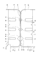
- FIG. 3 is a cross-sectional view showing a III-III cross section of FIG.
- the impact absorbing member 10 is attached to front and rear ends of a vehicle such as an automobile. In this embodiment, the impact absorbing member 10 attached to the front side of the vehicle will be described.
- the impact absorbing member 10 includes a cylindrical wall 18 and a flange portion 16.
- the cylinder wall 18 forms a rectangular cylinder.
- the flange portion 16 extends outward from the outer periphery of the cylindrical wall 18.
- the flange portion 16 also extends in the axial direction of the cylindrical wall 18.
- the shock absorbing member 10 includes a first main body 17 and a second main body 60.
- the first main body 17 has a first partial cylindrical wall 19 and first flange portions 20 and 21.
- the first partial cylinder wall 19 includes an upper wall 19a and two first side walls 19b.
- the first side wall 19b extends downward from the left and right ends of the upper wall 19a (both ends in the direction perpendicular to the axial direction of the cylindrical wall 18).
- the first partial cylinder wall 19 constitutes the upper half of the cylinder wall 18.
- An upper flange portion 12 and a front flange portion 14 that are in contact with the front bumper 2 of the vehicle are formed at the front end in the axial direction of the first partial cylinder wall 19 (the front end in the vehicle traveling direction).
- the upper flange portion 12 contacts the upper surface of the front bumper 2.
- the upper flange portion 12 is joined to the front bumper 2 by spot welding.
- the front flange portion 14 contacts the rear surface of the front bumper 2.
- the front flange portion 14 is joined to the front bumper 2 by spot welding.
- a rear flange portion 54 is formed at the rear end of the first partial cylinder wall 19 (the end on the rear side in the vehicle traveling direction). The rear flange portion 54 comes into contact with a vehicle body, for example, a side member.
- the rear flange portion 54 is joined to the vehicle main body by spot welding.
- Two upper grooves 34 that are recessed downward are formed on the upper wall 19 a of the first partial cylinder wall 19.
- the two upper grooves 34 are formed in parallel with each other with an interval in the axial direction of the cylindrical wall 18.
- Each upper groove 34 is formed perpendicular to the axial direction of the cylindrical wall 18.
- Each upper groove 34 is formed over the entire width in the width direction of the upper wall 19a (the direction perpendicular to the axial direction of the cylindrical wall 18).
- Each of the first side walls 19b is formed with an upper vertical groove 26 in front of the upper groove 34 on the front side.
- the upper vertical groove 26 is recessed inside the cylindrical wall 18.
- Each upper vertical groove 26 is formed at the same position in the axial direction of the cylindrical wall 18.
- the upper vertical groove 26 extends downward from the upper end of the first side wall 19b.
- the lower end of the upper vertical groove 26 is located above the lower end of the first side wall 19b.
- An upper vertical groove 40 is formed between the two upper grooves 34 in each of the first side walls 19b.
- the upper vertical groove 40 is recessed inside the cylindrical wall 18.
- the upper vertical groove 40 is formed in parallel with the upper vertical groove 26.
- the vertical length of the upper vertical groove 40 is substantially the same as the vertical length of the upper vertical groove 26.
- the width and depth of the upper vertical groove 40 are larger than those of the upper vertical groove 26.
- an upper vertical groove 48 is formed on the first side wall 19b behind the upper groove 34 on the rear side.
- the upper vertical groove 48 is formed in parallel with the upper vertical groove 26.
- the vertical length of the upper vertical groove 48 is substantially the same as the vertical length of the upper vertical groove 26.
- the width and depth of the upper vertical groove 48 are substantially the same as those of the upper vertical groove 40.
- 1st flange part 20 is formed in the lower end of one 1st side wall 19b.
- the first flange portion 20 extends toward the outside of the cylindrical wall 18. Further, the first flange portion 20 extends along the axial direction of the cylindrical wall 18.
- a first flange portion 21 is formed at the lower end of the other first side wall 19b. The first flange portion 21 extends toward the outside of the cylindrical wall 18. Further, the first flange portion 21 extends along the axial direction of the cylindrical wall 18.
- the first flange portion 21 is longer than the first flange portion 20 in the axial direction of the cylindrical wall 18.
- the first flange portion 21 has substantially the same length as the first flange portion 20 in the direction perpendicular to the axial direction of the cylindrical wall 18.
- the front ends of the first flange portions 20 and 21 are connected to the front flange portion 14.
- the rear ends of the first flange portions 20 and 21 are connected to the rear flange portion 54.
- An upper first bead 28 is formed on the first flange portion 21 located below the upper vertical groove 26.
- the upper first bead 28 has a triangular cross section in the axial direction of the cylindrical wall 18. As shown in FIG. 3, the height of the upper first bead 28 gradually decreases as it moves away from the end of the first flange portion 21 on the first side wall 19 b side to the outside of the first cylindrical wall 18.
- An upper second bead 24 is formed on the first flange portion 20 located below the upper vertical groove 26.
- the upper second bead 24 is formed at the same position as the upper first bead 28 in the axial direction of the cylindrical wall 18.
- the upper second bead 24 has a triangular cross section in the axial direction of the cylindrical wall 18. As shown in FIG.
- the height of the upper second bead 24 gradually decreases as it moves away from the end of the first flange portion 20 on the first side wall 19 b side to the outside of the cylindrical wall 18.
- the dimensions of the upper second bead 24 are smaller than the dimensions of the upper first bead 28.
- An upper third bead 38 is formed on each of the first flange portions 20 and 21 located below the upper vertical groove 40.
- the upper third bead 38 has a triangular cross section in the axial direction of the cylindrical wall 18.
- the height of the upper third bead 38 gradually decreases as the distance from the end on the first side wall 19b side of the first flange portions 20 and 21 to the outside of the cylindrical wall 18 increases.
- Each of the upper third beads 38 is formed at the same position in the axial direction of the cylindrical wall 18.
- Each of the upper third beads 38 has the same shape and size.
- the dimension of the upper third bead 38 is smaller than the dimension of the upper second bead 24.
- An upper fourth bead 46 is formed in each of the first flange portions 20 and 21 located below the upper vertical groove 48.
- the upper fourth bead 46 has a triangular cross section in the axial direction of the cylindrical wall 18.
- the height of the upper fourth bead 46 gradually decreases as it moves away from the end of the first flange portions 20, 21 on the first side wall 19 b side to the outside of the cylindrical wall 18.
- Each of the upper fourth beads 46 is formed at the same position in the axial direction of the cylindrical wall 18.
- Each of the upper fourth beads 46 has the same shape and size.
- the size of the upper fourth bead 46 is smaller than that of the upper third bead 38.
- the dimension of the upper fourth bead 46 may be the same as the dimension of the upper third bead 38.
- a second main body 60 is disposed below the first main body 17.
- the second main body 60 has a second partial cylindrical wall 62 and second flange portions 64 and 66.
- the second partial cylinder wall 62 includes a lower wall 62a and two second side walls 62b.
- the second side wall 62b extends upward from the left and right ends of the lower wall 62a.
- the second partial cylinder wall 62 constitutes the lower half of the cylinder wall 18.
- the first partial cylindrical wall 19 and the second partial cylindrical wall 62 of the cylindrical wall 18 form a rectangular cylinder.
- a front flange portion 61 that abuts against the front bumper 2 is formed at the front end of the second partial cylinder wall 62.
- the front flange portion 61 contacts the rear surface of the front bumper 2.
- the front flange portion 61 is joined to the front bumper 2 by spot welding.
- a rear flange portion 82 is formed at the rear end of the second partial cylinder wall 62.
- the rear flange portion 82 is in contact with the vehicle main body.
- the rear flange portion 82 is joined to the vehicle main body by spot welding.
- Two lower grooves 71 recessed upward are formed in the lower wall 62a of the second partial cylinder wall 62.
- the two lower grooves 71 are formed in parallel with each other with an interval in the axial direction of the cylindrical wall 18.
- Each lower groove 71 is formed perpendicular to the axial direction of the cylindrical wall 18.
- Each lower groove 71 is formed across the entire width of the lower wall 62a.
- Each lower groove 71 is arranged to face each upper groove 34 formed in the upper wall 19a.
- a lower vertical groove 70 is formed in front of the lower groove 71 on the front side in each of the second side walls 62b.
- the lower vertical groove 70 is recessed inside the cylindrical wall 18.
- each second side wall 62 b is formed at the same position with respect to the axial direction of the cylindrical wall 18.
- Each lower vertical groove 70 is formed on an extension of each upper vertical groove 26 formed in the first side wall 19b.
- the lower vertical groove 70 extends upward from the lower end of the second side wall 62b.
- the upper end of the lower vertical groove 70 is located below the upper end of the second side wall 62b.
- the lower vertical groove 70 has substantially the same vertical length, width, and depth as the upper vertical groove 26.
- a lower vertical groove 76 is formed between the two lower grooves 71.
- the lower vertical groove 76 is recessed inside the cylindrical wall 18.
- the lower vertical groove 76 is formed in parallel with the lower vertical groove 70.
- the lower vertical groove 76 formed in each second side wall 62 b is formed at the same position with respect to the axial direction of the cylindrical wall 18.
- Each lower vertical groove 76 is formed on an extension of each upper vertical groove 40 formed in the first side wall 19b.
- the lower vertical groove 76 extends upward from the lower end of the second side wall 62b.
- the length of the lower vertical groove 76 in the vertical direction is substantially the same as the length of the lower vertical groove 70.
- the width and depth of the lower longitudinal groove 76 are larger than the lower longitudinal groove 70 and are substantially the same as the upper longitudinal groove 40.
- a lower vertical groove 80 is formed behind the lower groove 71 on the second side wall 62b.
- the lower vertical groove 80 is recessed inside the cylindrical wall 18.
- the lower vertical groove 80 is formed in parallel with the lower vertical groove 70.
- the lower vertical groove 80 formed in each second side wall 62 b is formed at the same position with respect to the axial direction of the cylindrical wall 18.
- Each lower vertical groove 80 is formed on an extension of each upper vertical groove 48 formed in the first side wall 19b.
- the lower vertical groove 80 extends upward from the lower end of the second side wall 62b.
- the length of the lower vertical groove 80 is substantially the same as the length of the lower vertical groove 70.
- the width and depth of the lower vertical groove 80 are substantially the same as those of the upper vertical groove 48.
- a second flange portion 64 is formed at the upper end of one second side wall 62b.
- the second flange portion 64 extends toward the outside of the cylindrical wall 18. Further, the second flange portion 64 extends along the axial direction of the cylindrical wall 18.
- the second flange portion 64 is disposed so as to face the first flange portion 21.
- a second flange portion 66 is formed at the upper end of the other second side wall 62b.
- the second flange portion 66 extends toward the outside of the cylindrical wall 18. Further, the second flange portion 66 extends along the axial direction of the cylindrical wall 18.
- the second flange portion 66 is disposed so as to face the first flange portion 20.
- the second flange portion 64 is longer than the second flange portion 66 in the axial direction of the cylindrical wall 18 and has substantially the same length as the first flange portion 21.
- the second flange portion 66 has substantially the same length as the first flange portion 21 in the axial direction of the cylindrical wall 18. Further, the second flange portion 64 has substantially the same length as the second flange portion 66 in the direction perpendicular to the axial direction of the cylindrical wall 18 and substantially the same length as the first flange portion 21.
- the front ends of the second flange portions 64 and 66 are connected to the front flange portion 61.
- the rear ends of the second flange portions 64 and 66 are connected to the rear flange portion 82.
- a lower first bead 68 is formed on the second flange portion 64 located above the lower vertical groove 70.
- the lower first bead 68 is formed below the upper first bead 28.
- the lower first bead 68 has a symmetric shape and size with respect to the boundary surface X (see FIG. 3) between the first main body 17 and the second main body 60 with respect to the upper first bead 28.
- the upper first bead 28 and the lower first bead 68 form a gap between the end of the first flange portion 21 on the first side wall 19b side and the end of the second flange portion 64 on the second side wall 62b side.
- a lower second bead 72 is formed in the second flange portion 66 located above the lower vertical groove 70.
- the lower second bead 72 is formed below the upper second bead 24.
- the lower second bead 72 has a shape and dimensions that are symmetric with respect to the upper second bead 24 with respect to the boundary surface X.
- the upper second bead 24 and the lower second bead 72 form a gap between the end of the first flange portion 20 on the first side wall 19b side and the end of the second flange portion 66 on the second side wall 62b side. Has been.
- a lower third bead 74 is formed in each of the second flange portions 64 and 66 located above the lower vertical groove 76. Each lower third bead 74 is formed below each upper third bead 38.
- the lower third bead 74 has a shape and dimensions that are symmetric with respect to the upper third bead 38 with respect to the boundary surface X.
- the upper third bead 38 and the lower third bead 74 form a gap between the end of the first flange portion 21 on the first side wall 19b side and the end of the second flange portion 64 on the second side wall 62b side. Has been.
- the upper third bead 38 and the lower third bead 74 it is also between the end portion on the first side wall 19 b side of the first flange portion 20 and the end portion on the second side wall 62 b side of the second flange portion 66. A gap is formed.
- FIG. 4 is a cross-sectional view showing a cross section taken along line IV-IV in FIG.
- a lower fourth bead 78 is formed in each of the second flange portions 64 and 66 located above the lower vertical groove 80.
- Each lower fourth bead 78 is formed below each upper fourth bead 46.
- the lower fourth bead 78 has a shape and dimensions that are symmetric with respect to the fourth bead 46 with respect to the boundary surface X.
- the upper fourth bead 46 and the lower fourth bead 78 form a gap between the end of the first flange portion 21 on the first side wall 19b side and the end of the second flange portion 64 on the second side wall 62b side. Has been.
- each bead 68, 72, 74, 78 is smaller in the order of the lower first bead 68, the lower second bead 72, the lower third bead 74, and the lower fourth bead 78.
- the dimension of the lower third bead 74 may be the same as the dimension of the lower fourth bead 78.
- the first flange portion 21 and the second flange portion 64 are joined at four joint portions 36 by spot welding.
- the joint portion 36 includes a front end portion of the first flange portion 21, a space between the first beads 28, 68 and the third beads 38, 74, a third bead 38, 74 and a fourth bead. It is located between the beads 46 and 78 and the rear end portion of the first flange portion 21.
- Each bead 28, 38, 46, 68, 74, 78 is formed in a section where the first flange portion 21 and the second flange portion 64 are not joined in the axial direction of the cylindrical wall 18.
- the gap between the end of the first flange portion 21 on the first side wall 19b side and the end of the second flange portion 64 on the second side wall 62b side is such that the first flange portion 21 and the second flange portion 64 are It is formed in an unjoined section. Further, the joint portion 36 located between the beads is located at the same position as the upper groove 34 (lower groove 71) in the axial direction of the cylindrical wall 18.
- the first flange portion 20 and the second flange portion 66 are joined by three joint portions 36 by spot welding.
- the joining portion 36 is between the second beads 24, 72 and the third beads 38, 74, between the third beads 38, 74 and the fourth beads 46, 78, and the rear end portion of the first flange portion 20. Is located.
- the beads 24, 38, 46, 72, 74, and 78 are formed in a section where the first flange portion 20 and the second flange portion 66 are not joined in the axial direction of the cylindrical wall 18.
- the gap between the end portion of the first flange portion 20 on the first side wall 19b side and the end portion of the second flange portion 66 on the second side wall 62b side is determined by the first flange portion 20 and the second flange portion 66. It is formed in an unjoined section. Further, the joint portion 36 located between the beads is located at the same position as the upper groove 34 (lower groove 71) in the axial direction of the cylindrical wall 18.
- the impact absorbing member 10 When the impact absorbing member 10 is attached to the vehicle body and another object collides from the front of the vehicle, the impact absorbing member 10 is compressed and deformed in the axial direction of the cylindrical wall 18 to absorb the impact energy.
- the upper vertical grooves 26 and 70 are recessed inside the cylindrical wall 18 and deformed in a direction to close the gap formed by the first beads 28 and 68.
- the outer end portions of the first flange portion 21 and the second flange portion 64 at the position where the gap is formed (the position where the first beads 28 and 68 are formed) are separated from each other.
- the first flange portion 20 is deformed in the direction in which the gap formed by the second beads 24 and 72 is closed, and the gap is formed (at the position where the second beads 24 and 72 are formed). And the outer end of the second flange portion 66 are spaced apart from each other.
- Each flange part 20, 21, 64, 66 begins to deform at a position where a gap is formed. Thereby, the deformation position in the initial stage of the compression load of each flange part can be specified. When a compressive load is further applied from this state, the flange portions 20, 21, 64, 66 are further deformed and buckled and deformed at positions where the deformation has already started.
- the position where the load acts that is, the load applied to the front side of the vehicle is large.
- the beads 26, 28, 68, 72 located on the axial front end side of the cylinder 16 are larger than the beads positioned on the axially rear side of the cylinder 16.
- the vehicle front side is easily deformed.
- the upper side longitudinal grooves 26, 40, 48 are formed on the first side wall 19b at positions corresponding to the beads 24, 28, 38, 46 formed on the first flange portions 20, 21, respectively. Is formed.
- lower vertical grooves 70, 76, and 80 are formed in the second side wall 62b at positions corresponding to the beads 68, 72, 74, and 78 formed in the second flange portions 64 and 66, respectively.
- the first side walls 19b and 62b are located inside the cylindrical wall 18 at positions where the upper vertical grooves 26, 40 and 48 and the lower vertical grooves 70, 76 and 80 are formed. It is easy to deform. Thereby, it can suppress that the deformation
- the upper groove 34 is formed in the upper wall 19a
- the lower groove 71 is formed in the lower wall 62a.
- the upper groove 34 is displaced from the upper vertical grooves 26, 40, 48 in the axial direction of the cylindrical wall 18.
- the lower groove 71 is displaced from the lower vertical grooves 70, 76, 80 in the axial direction of the cylindrical wall 18.
- the first side walls 19b, 62b are recessed inside the cylinder wall 18 so that the upper walls 19a, 62a are outside the cylinder. Deforms into a convex shape. Thereby, it can suppress that the deformation
- the upper first bead 28 formed on the first flange portion 21 is in the same position as the upper second bead 24 formed on the first flange portion 20 with respect to the axial direction of the cylindrical wall 18. Is arranged. However, the positions of the upper first bead 28 and the upper second bead 24 in the axial direction of the cylindrical wall 18 may be different. Similarly, the positions of the beads formed in the shock absorbing member 10 at the same position in the axial direction of the cylindrical wall 18 may be different.
- the joint portion 36 between the first flange portion 20 and the second flange portion 66 is related to the joint portion 36 between the first flange portion 21 and the second flange portion 64 and the axial direction of the cylindrical wall 18. Arranged at the same position. However, the joint portion 36 between the first flange portion 20 and the second flange portion 66 and the joint portion 36 between the first flange portion 21 and the second flange portion 64 may be arranged at different positions in the axial direction.
- each bead may be appropriately changed according to the required strength, deformation amount, and the like.
- the shape of the bead for example, as shown in FIG. 5, the bead 100 may have a semiconical shape whose bottom surface is located on the first side wall 19 b and extends toward the outside of the first partial cylindrical wall 19.
- the bead 200 may have a semi-conical shape whose bottom surface is located at the first flange portion 21 and extends along the first side wall 19 b.
- the bead 300 may have a semi-cylindrical shape extending toward the outside of the first partial cylinder wall 19.
- the cylinder wall 18 forms a rectangular cylinder.
- the cylinder constituted by the cylinder wall may not be a quadrangle.
- it may be a circle or a polygon other than a rectangle such as a hexagon or an octagon.
Landscapes
- Engineering & Computer Science (AREA)
- Mechanical Engineering (AREA)
- General Engineering & Computer Science (AREA)
- Body Structure For Vehicles (AREA)
- Vibration Dampers (AREA)
- Refuge Islands, Traffic Blockers, Or Guard Fence (AREA)
Abstract
Description
本発明の衝撃吸収部材は、少なくとも第1本体と第2本体を備えている。第1本体は、第1部分筒壁と第1フランジ部を備えている。第1部分筒壁は、筒壁を周方向に分割した部分筒壁を構成する。第1フランジ部は、第1部分筒壁の周方向における両端の各々から筒の外側に向かって伸びているとともに、筒の軸方向にも伸びている。第2本体は、第2部分筒壁と第2フランジ部を備えている。第2部分筒壁は、筒壁を周方向に分割した部分筒壁を構成する。第2フランジ部は、第2部分筒壁の周方向における両端の各々から筒の外側に向かって伸びているとともに、筒の軸方向にも伸びている。第1フランジ部と第2フランジ部は、筒の軸方向において断続的に接合されている。そして、筒の軸方向において第1フランジ部と第2フランジ部が接合されていない区間の一部に、第1フランジ部の第1部分筒壁側の端部と第2フランジ部の第2部分筒壁側の端部の間に隙間が形成されている。
この衝撃吸収部材によれば、間隙を形成しておいた位置において順々に座屈変形が進行する。第1フランジと第2フランジの接合点は、座屈変形後も座屈変形前と同一平面内に留まっている。即ち、衝撃吸収部材の変形プロセスが安定する。
この衝撃吸収部材によれば、フランジ部における座屈変形の発生位置と、変形状態ないし変形プロセスが製品ごとにばらつくことを抑制することができる。これにより、衝撃吸収部材に負荷される圧縮荷重と圧縮変形量との関係が、製品ごとにばらつくことを抑制することができる。
衝撃吸収部材では、圧縮荷重が負荷された初期の状態において、荷重の作用位置に近い位置、即ち、車両本体から最も遠い位置に大きな荷重が負荷される。この衝撃吸収部材では、車両本体から最も遠くに位置する隙間が他の隙間よりも大きく形成されている。そのため、車両本体から最も遠くに位置する隙間が他の隙間よりも変形しやすい。これにより、圧縮荷重が負荷された初期の状態におけるフランジ部の変形位置がばらつくことを抑制することができる。この結果、衝撃吸収部材に負荷される圧縮荷重と圧縮変形量との関係が製品ごとにばらつくことを確実に抑制することができる。
この構成によれば、第1フランジ部の外側の端部と第2フランジ部の外側の端部とが離間しやすくなる。即ち、第1フランジ部と第2フランジ部が、隙間が形成されている位置で変形しやすくなる。これにより、より確実に、フランジ部を所望の位置で変形させることができる。
(特徴1) 衝撃吸収部材は、第1本体と第2本体以外に、第3本体をも備えていてもよい。この場合、第3本体は、筒壁を周方向に分割した部分筒壁を構成する第3部分筒壁と、第3部分筒壁の周方向の両端に形成されている一対の第3フランジを備えている。
この場合、第1フランジ部に第2フランジ部を接合し、第2フランジ部に第3フランジ部を接合し、第3フランジ部に第1フランジ部を接合する。第1部分筒壁と第2部分筒壁と第3部分筒壁によって筒が構成されている。
(特徴2) さらに、第4本体、第5本体等を備えている。筒壁を構成する部材数は任意である。
(特徴3) 筒壁を構成する部材数が3個の場合、第1フランジ部と第3フランジ部は、筒の軸方向において断続的に接合されており、第2フランジ部と第3フランジ部は、筒の軸方向において断続的に接合されている。そして、筒の軸方向において、第1フランジ部と第3フランジ部が接合されていない区間の一部に、第1フランジ部の第1部分筒壁側の端部と第3フランジ部の第3部分筒壁側の端部の間に隙間が形成されており、筒の軸方向において第2フランジ部と第3フランジ部が接合されていない区間の一部に、第2フランジ部の第2部分筒壁側の端部と第3フランジ部の第3部分筒壁側の端部の間に隙間が形成されている。この構成によれば、衝撃吸収部材に負荷される圧縮荷重と圧縮変形量との関係が衝撃吸収部材ごとにばらつくことを抑制することができる。
(特徴4) 第1フランジ部と第2フランジ部との隙間(接合される一対のフランジ部の隙間)は、接合されていない区間ごとに1個ずつが形成されていてもよく、区間ごとに2個以上形成されていてもよい。また、区間ごとに隙間の個数が異なっていてもよい。また隙間が形成されていない区間があってもよい。これらの構成によっても、衝撃吸収部材に負荷される圧縮荷重と圧縮変形量との関係が衝撃吸収部材ごとにばらつくことを抑制することができる。
図3は、図1のIII―III断面を示す断面図である。
衝撃吸収部材10は、例えば自動車等の車両の前後端部に取り付けられる。本実施例では、車両の前側に取り付けられる衝撃吸収部材10について説明する。
図1,2,3に示すように、衝撃吸収部材10は、筒壁18とフランジ部16を備えている。筒壁18は、四角形の筒を構成している。フランジ部16は、筒壁18の外周から外側に向かって伸びている。フランジ部16は、筒壁18の軸方向にも伸びている。
衝撃吸収部材10は、第1本体17と第2本体60を備えている。
第1側壁19bのそれぞれには、前側の上溝34よりも前方に上側縦溝26が形成されている。上側縦溝26は、筒壁18の内側に凹んでいる。各上側縦溝26は、筒壁18の軸方向に関して同一の位置に形成されている。上側縦溝26は、第1側壁19bの上端から下方に向かって伸びている。上側縦溝26の下端は、第1側壁19bの下端よりも上方に位置している。第1側壁19bのそれぞれには、2本の上溝34の間に上側縦溝40が形成されている。上側縦溝40は、筒壁18の内側に凹んでいる。上側縦溝40は、上側縦溝26と平行に形成されている。上側縦溝40の上下方向の長さは、上側縦溝26の上下方向の長さと略同一である。上側縦溝40の幅と深さは、上側縦溝26よりも大きい。また、第1側壁19bには、後側の上溝34よりも後方に上側縦溝48が形成されている。上側縦溝48は、上側縦溝26と平行に形成されている。上側縦溝48の上下方向の長さは、上側縦溝26の上下方向の長さと略同一である。上側縦溝48の幅と深さは、上側縦溝40と略同一である。
第2側壁62bのそれぞれには、前側の下溝71よりも前方に下側縦溝70が形成されている。下側縦溝70は、筒壁18の内側に凹んでいる。各第2側壁62bに形成された下側縦溝70は、筒壁18の軸方向に関して同一の位置に形成されている。また、各下側縦溝70は、第1側壁19bに形成された各上側縦溝26の延長上に形成されている。下側縦溝70は、第2側壁62bの下端から上方に向かって伸びている。下側縦溝70の上端は、第2側壁62bの上端よりも下方に位置している。下側縦溝70は、上側縦溝26と略同一の上下方向の長さ、幅、深さを有している。
下側縦溝70の上方に位置する第2フランジ部66には、下側第2ビード72が形成されている。下側第2ビード72は、上側第2ビード24の下方に形成されている。下側第2ビード72は、境界面Xに関して上側第2ビード24と対称な形状及び寸法を有している。上側第2ビード24と下側第2ビード72により、第1フランジ部20の第1側壁19b側の端部と第2フランジ部66の第2側壁62b側の端部との間に隙間が形成されている。
各ビード68,72,74,78の寸法は、下側第1ビード68、下側第2ビード72、下側第3ビード74、下側第4ビード78の順で小さくなっている。下側第3ビード74の寸法は、下側第4ビード78の寸法と同一であってもよい。
また、衝撃吸収部材10では、第1側壁19bには、第1フランジ部20,21に形成された各ビード24,28,38,46に対応する位置に、それぞれ上側縦溝26,40,48が形成されている。また、第2側壁62bには、第2フランジ部64,66に形成された各ビード68,72,74,78に対応する位置に、それぞれ下側縦溝70,76,80が形成されている。衝撃吸収部材10が圧縮荷重により圧縮変形すると、上側縦溝26,40,48、下側縦溝70,76,80が形成されている位置で、第1側壁19b,62bが筒壁18の内側に変形しやすくなっている。これにより、衝撃吸収部材10の変形状態ないし変形プロセスが、製品ごとにばらつくことを抑制することができる。
上記した衝撃吸収部材10では、第1フランジ部21に形成された上側第1ビード28は、第1フランジ部20に形成された上側第2ビード24と筒壁18の軸方向に関して同一の位置に配置されている。しかしながら、上側第1ビード28と上側第2ビード24の筒壁18の軸方向に関する位置は、異なっていてもよい。同様に、衝撃吸収部材10に筒壁18の軸方向に関して同一の位置に形成されているビードは、その位置が異なっていてもよい。
上記した衝撃吸収部材10では、第1フランジ部20と第2フランジ部66との接合部36は、第1フランジ部21と第2フランジ部64との接合部36と筒壁18の軸方向に関して同一の位置に配置されている。しかしながら、第1フランジ部20と第2フランジ部66との接合部36と第1フランジ部21と第2フランジ部64との接合部36は、軸方向に関して異なる位置に配置されていてもよい。
また、全てのビード形状が同一であってもよいし、一部のビードが、他のビードと異なる形状であってもよい。
また、上記した衝撃吸収部材10では、筒壁18は、四角形の筒を構成している。しかしながら、筒壁によって構成される筒は、四角形でなくてもよい。例えば、円形であってもよく、六角形や八角形等の四角形以外の多角形であってもよい。
また、本明細書または図面に説明した技術要素は、単独であるいは各種の組合せによって技術的有用性を発揮するものであり、出願時の請求項記載の組合せに限定されるものではない。また、本明細書または図面に例示した技術は、複数目的を同時に達成するものであり、そのうちの一つの目的を達成すること自体で技術的有用性を持つものである。
Claims (3)
- 筒を構成する筒壁と、筒壁の外周から外側に向かって伸びているとともに筒の軸方向にも伸びているフランジ部を有しており、軸方向の一端を車両本体に取り付けて用いられ、車両の衝突時に筒壁とフランジ部が軸方向に圧縮変形する衝撃吸収部材であって、
少なくとも第1本体と第2本体を備えており、
第1本体は、筒壁を周方向に分割した部分筒壁を構成する第1部分筒壁と、第1部分筒壁の周方向における両端の各々から筒の外側に向かって伸びているとともに筒の軸方向にも伸びている第1フランジ部を備えており、
第2本体は、筒壁を周方向に分割した部分筒壁を構成する第2部分筒壁と、第2部分筒壁の周方向における両端の各々から筒の外側に向かって伸びているとともに筒の軸方向にも伸びている第2フランジ部を備えており、
第1フランジ部と第2フランジ部は、筒の軸方向において断続的に接合されており、
筒の軸方向において第1フランジ部と第2フランジ部が接合されていない区間の一部に、第1フランジ部の第1部分筒壁側の端部と第2フランジ部の第2部分筒壁側の端部の間に隙間が形成されている衝撃吸収部材。 - 前記区間ごとに1個の隙間が形成されており、
車両本体から最も遠くに位置する隙間が他の隙間よりも大きいことを特徴とする請求項1に記載の衝撃吸収部材。 - 前記隙間が、筒壁から外側に遠ざかるにつれて小さくなることを特徴とする請求項1又は2に記載の衝撃吸収部材。
Priority Applications (5)
| Application Number | Priority Date | Filing Date | Title |
|---|---|---|---|
| EP08791463.6A EP2301809B1 (en) | 2008-07-23 | 2008-07-23 | Impact absorption member |
| CN2008801281240A CN102015376B (zh) | 2008-07-23 | 2008-07-23 | 撞击力吸收部件 |
| US12/921,164 US7980607B2 (en) | 2008-07-23 | 2008-07-23 | Impact absorbing member |
| JP2010521561A JP5261490B2 (ja) | 2008-07-23 | 2008-07-23 | 衝撃吸収部材 |
| PCT/JP2008/063206 WO2010010618A1 (ja) | 2008-07-23 | 2008-07-23 | 衝撃吸収部材 |
Applications Claiming Priority (1)
| Application Number | Priority Date | Filing Date | Title |
|---|---|---|---|
| PCT/JP2008/063206 WO2010010618A1 (ja) | 2008-07-23 | 2008-07-23 | 衝撃吸収部材 |
Publications (1)
| Publication Number | Publication Date |
|---|---|
| WO2010010618A1 true WO2010010618A1 (ja) | 2010-01-28 |
Family
ID=41570097
Family Applications (1)
| Application Number | Title | Priority Date | Filing Date |
|---|---|---|---|
| PCT/JP2008/063206 Ceased WO2010010618A1 (ja) | 2008-07-23 | 2008-07-23 | 衝撃吸収部材 |
Country Status (5)
| Country | Link |
|---|---|
| US (1) | US7980607B2 (ja) |
| EP (1) | EP2301809B1 (ja) |
| JP (1) | JP5261490B2 (ja) |
| CN (1) | CN102015376B (ja) |
| WO (1) | WO2010010618A1 (ja) |
Cited By (1)
| Publication number | Priority date | Publication date | Assignee | Title |
|---|---|---|---|---|
| WO2013079680A1 (en) | 2011-12-02 | 2013-06-06 | Rockwool International A/S | Aqueous binder composition |
Families Citing this family (20)
| Publication number | Priority date | Publication date | Assignee | Title |
|---|---|---|---|---|
| US8539737B2 (en) | 2008-09-19 | 2013-09-24 | Ford Global Technologies, Llc | Twelve-cornered strengthening member |
| ITBO20110137A1 (it) * | 2011-03-21 | 2012-09-22 | Pasquale Impero | Assorbitore d'urto per veicoli a motore |
| US9381881B2 (en) * | 2011-08-09 | 2016-07-05 | Nippon Steel & Sumitomo Metal Corporation | Shock absorbing member |
| DE102011112256A1 (de) * | 2011-09-02 | 2013-03-07 | GM Global Technology Operations LLC (n. d. Gesetzen des Staates Delaware) | Kraftfahrzeug mit Crashbox |
| US10315698B2 (en) | 2015-06-24 | 2019-06-11 | Ford Global Technologies, Llc | Sixteen-cornered strengthening member for vehicles |
| US9944323B2 (en) | 2015-10-27 | 2018-04-17 | Ford Global Technologies, Llc | Twenty-four-cornered strengthening member for vehicles |
| GB2544795A (en) | 2015-11-27 | 2017-05-31 | Ford Global Tech Llc | A structural member |
| US9889887B2 (en) | 2016-01-20 | 2018-02-13 | Ford Global Technologies, Llc | Twelve-cornered strengthening member for a vehicle with straight and curved sides and an optimized straight side length to curved side radius ratio |
| US9789906B1 (en) * | 2016-03-23 | 2017-10-17 | Ford Global Technologies, Llc | Twenty-eight-cornered strengthening member for vehicles |
| US10393315B2 (en) | 2016-04-26 | 2019-08-27 | Ford Global Technologies, Llc | Cellular structures with twelve-cornered cells |
| US10704638B2 (en) | 2016-04-26 | 2020-07-07 | Ford Global Technologies, Llc | Cellular structures with twelve-cornered cells |
| US10473177B2 (en) | 2016-08-23 | 2019-11-12 | Ford Global Technologies, Llc | Cellular structures with sixteen-cornered cells |
| US10220881B2 (en) | 2016-08-26 | 2019-03-05 | Ford Global Technologies, Llc | Cellular structures with fourteen-cornered cells |
| US10279842B2 (en) | 2016-08-30 | 2019-05-07 | Ford Global Technologies, Llc | Twenty-eight-cornered strengthening member for vehicles |
| US10300947B2 (en) | 2016-08-30 | 2019-05-28 | Ford Global Technologies, Llc | Twenty-eight-cornered strengthening member for vehicles |
| US10429006B2 (en) | 2016-10-12 | 2019-10-01 | Ford Global Technologies, Llc | Cellular structures with twelve-cornered cells |
| JP7053421B2 (ja) * | 2018-09-17 | 2022-04-12 | 本田技研工業株式会社 | 車体構造 |
| JP7224827B2 (ja) * | 2018-09-21 | 2023-02-20 | 株式会社Subaru | 車体構造 |
| US11292522B2 (en) | 2019-12-04 | 2022-04-05 | Ford Global Technologies, Llc | Splayed front horns for vehicle frames |
| JP7537225B2 (ja) * | 2020-10-22 | 2024-08-21 | マツダ株式会社 | パネル接合構造 |
Citations (4)
| Publication number | Priority date | Publication date | Assignee | Title |
|---|---|---|---|---|
| JPS52123926U (ja) * | 1976-03-17 | 1977-09-20 | ||
| JPH107032A (ja) * | 1996-06-25 | 1998-01-13 | Daihatsu Motor Co Ltd | 車両用牽引フックの構造 |
| JP2000081069A (ja) | 1998-09-05 | 2000-03-21 | Press Kogyo Co Ltd | 車両用衝撃吸収部材とその製造方法 |
| JP3205076U (ja) | 2016-02-08 | 2016-07-07 | 東京エレクトロン株式会社 | 処理液供給装置 |
Family Cites Families (10)
| Publication number | Priority date | Publication date | Assignee | Title |
|---|---|---|---|---|
| JPS63129676U (ja) * | 1987-02-19 | 1988-08-24 | ||
| FR2712950B1 (fr) * | 1993-11-25 | 1995-12-29 | Gec Alsthom Transport Sa | Dispositifs et procédé d'amortissement de choc, ossature et véhicule comportant de tels dispositifs d'amortissement de choc. |
| WO2004020256A1 (ja) * | 2002-08-27 | 2004-03-11 | Kaneka Corporation | 車両用衝突エネルギー吸収材及びそれを用いた車両の衝突エネルギー吸収構造 |
| EP1714834A1 (en) * | 2004-02-10 | 2006-10-25 | Sango Co., Ltd. | Impact absorbing device of vehicle |
| JP4723942B2 (ja) | 2004-09-28 | 2011-07-13 | アイシン精機株式会社 | 車両の衝撃吸収具及び車両の衝撃吸収構造 |
| CN2774862Y (zh) * | 2005-02-21 | 2006-04-26 | 重庆益弘工程塑料制品有限公司 | 车辆冲击能量吸收缓冲装置 |
| JP2006347265A (ja) | 2005-06-14 | 2006-12-28 | Toyota Motor Corp | 車両の衝撃吸収部材 |
| JP4350731B2 (ja) * | 2006-07-11 | 2009-10-21 | 豊田鉄工株式会社 | 車両用衝撃吸収部材 |
| JP4752727B2 (ja) * | 2006-10-31 | 2011-08-17 | トヨタ自動車株式会社 | 車両のピラー部構造 |
| DE102007035483B4 (de) * | 2007-07-28 | 2013-11-07 | Dr. Ing. H.C. F. Porsche Aktiengesellschaft | Crasheinrichtung |
-
2008
- 2008-07-23 US US12/921,164 patent/US7980607B2/en not_active Expired - Fee Related
- 2008-07-23 CN CN2008801281240A patent/CN102015376B/zh not_active Expired - Fee Related
- 2008-07-23 WO PCT/JP2008/063206 patent/WO2010010618A1/ja not_active Ceased
- 2008-07-23 EP EP08791463.6A patent/EP2301809B1/en not_active Not-in-force
- 2008-07-23 JP JP2010521561A patent/JP5261490B2/ja not_active Expired - Fee Related
Patent Citations (4)
| Publication number | Priority date | Publication date | Assignee | Title |
|---|---|---|---|---|
| JPS52123926U (ja) * | 1976-03-17 | 1977-09-20 | ||
| JPH107032A (ja) * | 1996-06-25 | 1998-01-13 | Daihatsu Motor Co Ltd | 車両用牽引フックの構造 |
| JP2000081069A (ja) | 1998-09-05 | 2000-03-21 | Press Kogyo Co Ltd | 車両用衝撃吸収部材とその製造方法 |
| JP3205076U (ja) | 2016-02-08 | 2016-07-07 | 東京エレクトロン株式会社 | 処理液供給装置 |
Non-Patent Citations (1)
| Title |
|---|
| See also references of EP2301809A4 * |
Cited By (1)
| Publication number | Priority date | Publication date | Assignee | Title |
|---|---|---|---|---|
| WO2013079680A1 (en) | 2011-12-02 | 2013-06-06 | Rockwool International A/S | Aqueous binder composition |
Also Published As
| Publication number | Publication date |
|---|---|
| CN102015376A (zh) | 2011-04-13 |
| US20110012389A1 (en) | 2011-01-20 |
| EP2301809A4 (en) | 2011-12-21 |
| JPWO2010010618A1 (ja) | 2012-01-05 |
| US7980607B2 (en) | 2011-07-19 |
| CN102015376B (zh) | 2013-03-27 |
| EP2301809B1 (en) | 2013-06-12 |
| JP5261490B2 (ja) | 2013-08-14 |
| EP2301809A1 (en) | 2011-03-30 |
Similar Documents
| Publication | Publication Date | Title |
|---|---|---|
| JP5261490B2 (ja) | 衝撃吸収部材 | |
| TWI583579B (zh) | Collision box and manufacturing method thereof | |
| US7896411B2 (en) | Impact absorbing member for vehicle | |
| JP5949925B2 (ja) | クラッシュボックス及び自動車車体 | |
| US9126551B2 (en) | Shock absorber for motor vehicles | |
| WO2013024883A1 (ja) | 衝撃吸収部材 | |
| JP6913029B2 (ja) | エネルギー吸収部材 | |
| JP5561691B2 (ja) | 衝撃吸収部材 | |
| JP6070656B2 (ja) | 車両用衝撃吸収ボックス | |
| KR20130126716A (ko) | 금속제 중공 기둥 형상 부재 | |
| JP2008261493A (ja) | 衝撃吸収部材及びその製造方法 | |
| JP2015080998A (ja) | クラッシュボックス | |
| JP5486251B2 (ja) | 車両用衝撃吸収具及び車両用バンパ装置 | |
| WO2015145835A1 (ja) | 車両用バンパーリインフォースメント | |
| US8888151B2 (en) | Vehicle body rear structure | |
| CN204801698U (zh) | 吸能盒 | |
| WO2014126183A1 (ja) | エネルギー吸収部材 | |
| US9296425B2 (en) | Discontinuous multi-overlapped vehicle body member | |
| JP7068911B2 (ja) | バンパー部材 | |
| JP5552994B2 (ja) | サイドメンバ構造 | |
| JP2009073226A (ja) | 車枠用サイドメンバの衝撃吸収構造 | |
| WO2019176408A1 (ja) | 車両用構造部材 |
Legal Events
| Date | Code | Title | Description |
|---|---|---|---|
| WWE | Wipo information: entry into national phase |
Ref document number: 200880128124.0 Country of ref document: CN |
|
| WWE | Wipo information: entry into national phase |
Ref document number: 2008791463 Country of ref document: EP |
|
| 121 | Ep: the epo has been informed by wipo that ep was designated in this application |
Ref document number: 08791463 Country of ref document: EP Kind code of ref document: A1 |
|
| WWE | Wipo information: entry into national phase |
Ref document number: 2010521561 Country of ref document: JP |
|
| WWE | Wipo information: entry into national phase |
Ref document number: 3262/KOLNP/2010 Country of ref document: IN |
|
| WWE | Wipo information: entry into national phase |
Ref document number: 12921164 Country of ref document: US |
|
| NENP | Non-entry into the national phase |
Ref country code: DE |