WO2010021116A1 - サイドウイングリンクチェーン - Google Patents
サイドウイングリンクチェーン Download PDFInfo
- Publication number
- WO2010021116A1 WO2010021116A1 PCT/JP2009/003910 JP2009003910W WO2010021116A1 WO 2010021116 A1 WO2010021116 A1 WO 2010021116A1 JP 2009003910 W JP2009003910 W JP 2009003910W WO 2010021116 A1 WO2010021116 A1 WO 2010021116A1
- Authority
- WO
- WIPO (PCT)
- Prior art keywords
- side wing
- link
- chain
- pin
- hollow pin
- Prior art date
- Legal status (The legal status is an assumption and is not a legal conclusion. Google has not performed a legal analysis and makes no representation as to the accuracy of the status listed.)
- Ceased
Links
Images





Classifications
-
- B—PERFORMING OPERATIONS; TRANSPORTING
- B65—CONVEYING; PACKING; STORING; HANDLING THIN OR FILAMENTARY MATERIAL
- B65G—TRANSPORT OR STORAGE DEVICES, e.g. CONVEYORS FOR LOADING OR TIPPING, SHOP CONVEYOR SYSTEMS OR PNEUMATIC TUBE CONVEYORS
- B65G17/00—Conveyors having an endless traction element, e.g. a chain, transmitting movement to a continuous or substantially-continuous load-carrying surface or to a series of individual load-carriers; Endless-chain conveyors in which the chains form the load-carrying surface
- B65G17/06—Conveyors having an endless traction element, e.g. a chain, transmitting movement to a continuous or substantially-continuous load-carrying surface or to a series of individual load-carriers; Endless-chain conveyors in which the chains form the load-carrying surface having a load-carrying surface formed by a series of interconnected, e.g. longitudinal, links, plates, or platforms
- B65G17/067—Conveyors having an endless traction element, e.g. a chain, transmitting movement to a continuous or substantially-continuous load-carrying surface or to a series of individual load-carriers; Endless-chain conveyors in which the chains form the load-carrying surface having a load-carrying surface formed by a series of interconnected, e.g. longitudinal, links, plates, or platforms the load carrying surface being formed by plates or platforms attached to more than one traction element
Definitions
- the present invention is a side wing link chain in which a roller chain mechanism that meshes with a sprocket is incorporated on both the left and right sides of a conveyor portion that constitutes a conveying surface with a plurality of belt links via connecting pins that endlessly connect the belt links.
- a roller chain mechanism that meshes with a sprocket is incorporated on both the left and right sides of a conveyor portion that constitutes a conveying surface with a plurality of belt links via connecting pins that endlessly connect the belt links.
- the present invention relates to a side wing link chain suitable as an attached chip conveying conveyor.
- a side wing link chain having a configuration shown in FIG. 7 is known.
- this side wing link chain 500 hinge portions 511 are provided at the front and rear ends of the belt link 510, side wings 512 are fixed to the left and right ends by welding means, and a roller chain mechanism 520 is connected to connect the belt link 510. It is provided on both the left and right sides.
- the roller chain mechanism 520 includes a pair of outer link plates 521 and 522, a pair of rollers 523, a pair of inner link plates 524 and 525, and a bush 526, and a connecting pin 530 and a hinge portion 511 of the belt link 510.
- the pin holes 527 of the outer link plates 521 and 522 and the bushes 526 that support the rollers 523 are passed through and connected to each other (see, for example, Patent Document 1). *
- a side wing link chain is also known which has a simplified structure with the side wing as a part of the roller chain mechanism.
- hinge portions 611 are provided at the front and rear ends of the belt link 610, and side wings 612 are disposed at the left and right ends.
- a step 629 corresponding to the thickness in the front-rear direction is provided at the center of the side wing 612, and a pair of pin holes 627, 628 are provided in the front-rear direction for inserting the connecting pin 630 below the side 612. .
- the roller chain mechanism 620 includes a side wing 612, a roller 623, and a chain link 631.
- the chain link 631 is provided with pin holes 632 and 633 that pass through the connecting pin 630 in the front and rear, and the pin of the chain link 631.
- An offset step 635 substantially equal to the thickness of the chain link 631 is provided between the holes 632 and 633.
- the present invention solves the problems of the prior art as described above. That is, the object of the present invention is to reduce the sliding wear of the connecting pins and pin holes, and to reduce the gaps and backlash and to increase the dimensional accuracy. Another object of the present invention is to provide a side wing link chain with less obstacles such as a conveyance object such as processing waste biting into a gap.
- a roller chain mechanism that meshes with the sprocket is incorporated on both the left and right sides of the conveyor portion that constitutes the conveying surface by a large number of belt links via connecting pins that connect the belt links endlessly.
- the roller chain mechanism includes at least a connection pin extending from each belt link, a hollow pin pivotally supported by the connection pin, a bush pivotally supported by the hollow pin, and the bush.
- a roller supported on the belt, side wings arranged on the sides of each belt link and having an offset step on the front and back, and a chain link having an offset step opposite to the side wing, the side wing and the Chain links are located in areas where the distance is large due to the offset in the front-rear direction.
- Serial hollow pins hollow pins holes for fitting the by that it comprises a bushing hole for fitting the bush into partial intervals smaller by the offset in the longitudinal direction, is to solve the above problems.
- At least one of the hollow pins is a linear shape in which a part of the outer periphery of the end portion on the side wing side is notched. Further, at least one of the hollow pin holes of the side wing is formed in a part of the inner periphery in a straight line shape and closely fits with the hollow pin, thereby further solving the above problem.
- the invention according to claim 5 is characterized in that the side wing is integrated with the belt link from a single material.
- the invention according to claim 6 includes a part or all of the offset step.
- the above-mentioned problem is further solved by adopting an arc shape centering on the connecting pin.
- the chain link in addition to the configuration of the side wing link chain according to any one of claims 1 to 6, the chain link has a distance between upper and lower end surfaces in a central portion in a longitudinal direction. Is a narrow shape, which further solves the above problem.
- the roller in addition to the configuration of the side wing link chain according to any one of the first to seventh aspects, has a length of 0.5 to 1 mm from the bush. By having a clearance of 1 to 2 mm with the wing and the chain link, the above problem is further solved.
- the side wing link chain has a roller chain mechanism that meshes with a sprocket on both the left and right sides of a conveyor portion that is configured by a number of belt links to form a conveying surface, via connection pins that endlessly connect the belt links.
- the roller chain mechanism includes at least a connection pin extending from each belt link, a hollow pin pivotally supported by each connection pin, a bush pivotally supported by the hollow pin, A roller supported by a bush, a side wing that is disposed on the side of each belt link and has an offset step on the front and back, and a chain link that has an offset step opposite to the side wing.
- each part has a large interval due to the offset in the front-rear direction. Since the hollow pin hole that fits the hollow pin and the bush hole that fits the bush in the part where the gap is small due to the offset in the front-rear direction, the side wing and chain link do not slide directly on the connecting pin, so sliding Wear can be prevented, and the roller chain mechanism can be assembled with high precision by using hollow pins and bushes. Therefore, there can be provided a side wing link chain with few gaps and backlash and high dimensional accuracy.
- At least 1 of a hollow pin is a part of outer periphery of the edge part by the side wing side.
- a joint that is formed in a cut-out linear shape and requires that at least one of the hollow pin holes of the side wing is formed in a linear shape at a part of the inner periphery and closely fits with the hollow pin so that it can be attached and detached. Since the side wing and hollow pin do not slide even at the part, sliding wear can be prevented and assembly can be performed with high accuracy. Can be provided.
- the side wing link chain of the invention according to claim 3 is formed in a straight line shape in which a part of the outer periphery on the side wing side of the hollow pin is cut out in addition to the effect exerted by the side wing link chain according to claim 2. Since the end portion is within the range of the thickness of the side wing, the hollow pin does not protrude to the belt link side at the time of assembly in the joint portion that needs to be detachable. It is not necessary to provide an extra gap between them, and it is easy to attach and detach during maintenance and can be assembled with high accuracy. Therefore, there can be provided a side wing link chain with little gap and backlash and high dimensional accuracy. *
- the side wing link chain of the invention according to claim 5 in addition to the effect produced by the side wing link chain according to any one of claims 1 to 4, the side wing is a single unit with the belt link.
- the side wing link chain By being integrally formed from the above materials, there is no gap or distortion due to welding, and therefore there can be provided a side wing link chain with less gaps and backlash and high dimensional accuracy.
- the side wing link chain of the invention in addition to the effect produced by the side wing link chain according to any one of claims 1 to 5, the side wing is one of the offset steps. Since the part or all of the part has an arc shape centered on the connecting pin, even if the side wing link chain is bent, the gap between the stepped part and the end part of the front and rear side wings can be kept constant. It is possible to prevent troubles such as a conveyance object such as a bite in the gap. *
- the chain link has a central portion in the longitudinal direction.
- the gap between the upper and lower end surfaces is narrow, so even if the driven side on which the chain link is hung is made into a cylindrical boss without a sprocket, a clearance can be secured between the boss and the structure is simplified.
- the roller in addition to the effect exhibited by the side wing link chain according to any one of claims 1 to 7, the roller includes a bush and 0.5 to By having a clearance of 1 mm, 1 mm, side wings, and chain links, it is possible to prevent obstacles such as workpieces and the like being caught without disturbing the rotation of the rollers.
- the side wing link chain of the present invention is a side in which a roller chain mechanism that meshes with a sprocket is incorporated on both the left and right sides of a conveyor portion that constitutes a conveying surface with a plurality of belt links via connecting pins that endlessly connect the belt links.
- the roller chain mechanism includes at least a connecting pin extending from each belt link, a hollow pin supported by each connecting pin, a bush supported by the hollow pin, and a bush supported by the bush.
- a side wing disposed on the side of each belt link and having an offset step on the front and back, and a chain link having an offset step opposite to the side wing.
- the side wing and the chain link are respectively in the front-rear direction.
- the hollow pin is inserted in the part where the interval is large by the offset of Hollow pin holes to be joined and bush holes to fit the bushes in a portion where the gap is small due to offset in the front-rear direction, there is less sliding wear of the connecting pins and pin holes, and there are few gaps and backlash, high dimensional accuracy, machining scraps As long as there are few obstacles such as a transported object such as a bite in the gap, any specific embodiment may be used. *
- the side wing link chain of the present invention may be a transport conveyor for transporting granules and powder, transports a transport conveyor for transporting other solid bodies, viscous bodies, fluids, etc., or a mixture thereof. It may be a transfer conveyor, especially machining scraps generated by machining of machine tools such as cutting scraps such as lathes, milling machines, machining centers, cutting scraps such as laser processing machines and electric discharge machines, press scraps such as press machines, etc. It is suitable as a transfer conveyor for transferring the chips.
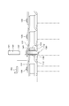
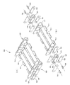
- the perspective view of the side wing link chain which is one Example of this invention.
- the top view of a part of side wing link chain shown in FIG. The side view of the side wing link chain shown in FIG.
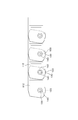
- the side view from the belt link side of the side wing link chain shown in FIG. The side view from the belt link side of the side wing link chain which is the other Example of this invention.
- the perspective view of the belt link integrated with the side wing which is further another Example of this invention.
- the perspective view of the conventional side wing link chain The perspective view of the other conventional side wing link chain.
- Stepped portions 130, 230, 530, 630 Connection pins 131, 631 ... Chain links 632 ... Pin holes 633 ... Pin holes 132 ⁇ ⁇ ⁇ Through hole 133 ⁇ ⁇ ⁇ Bush hole 134 ⁇ ⁇ ⁇ Hollow pin hole 135, 635 ⁇ ⁇ ⁇ Offset step 136 ⁇ ⁇ ⁇ Caulking part 137 ⁇ ⁇ ⁇ Eave part 140 ⁇ ⁇ ⁇ Hollow pin 141 ⁇ ⁇ ⁇ Through hole 142 ... Notch 150 ... Pin
- a side wing link chain 100 will be described with reference to FIGS.
- Hinge portions 111 are provided at the front and rear ends of the belt link 110, and side wings 112 are disposed at the left and right ends of the belt link 110.
- a step portion 129 corresponding to the thickness in the front-rear direction is provided, and a slit 115 is formed below a portion that spreads outward by the step portion 129.
- a bushing hole 113 is formed on the axis of the hinge portion 111 that is outwardly expanded by the stepped portion 129 of the side wing 112, and a hollow pin hole 114 is formed on the axis of the hinge portion 111 that is narrowed inward by the stepped portion 129. are provided respectively. *
- the roller chain mechanism 120 includes a side wing 112, a roller 123, a chain link 131, a bush 126 and a hollow pin 140.
- a hollow pin hole 134 is provided, and an offset step 135 approximately equal to the thickness of the chain link 131 is provided between the bush hole 133 and the hollow pin hole 134 of the chain link 131.
- the hollow pin 140 is cylindrical and is pivotally supported by the connecting pin 130, and both ends are fitted in the hollow pin hole 114 of the side wing 112 and the hollow pin hole 134 of the chain link 131.
- the bush 126 has a cylindrical shape and is pivotally supported by the hollow pin 140. Both ends of the bush 126 are fitted in the bush hole 114 of the side wing 112 and the bush hole 134 of the chain link 131.
- the roller 123 is cylindrical and is pivotally supported by the bush 126 and is configured to mesh with a sprocket (not shown).
- the side wing link chain 100 is configured by connecting in a shape.
- At least one part of the entire side wing link chain 100 requires a detachable joint part for disassembly / assembly.
- the structure differs between the joint part and other parts.
- the connecting pin 130 other than the joint portion has a flange 137 formed at one end, and the other end protrudes through the hinge portion 111 and the hollow pin 140 of the belt link 110 to form a crimped portion 136.
- a stopper is formed in both directions.
- the hollow pins 140 other than the joint portion have a simple cylindrical shape and have a length that protrudes outward from the hollow pin hole 134 of the chain link 131, and when the crimping portion 136 is formed at the end of the connecting pin 130. The crimping force can be received by the hollow pin 140, and the deformation and position fluctuation of the chain link 131 can be prevented.
- the hollow pin 140 of the joint portion has a length that protrudes outward from the hollow pin hole 134 of the chain link 131, and the protruding portion has a through hole 142 into which the pin 150 is inserted in the diameter direction.
- the connecting pin 130 of the joint portion has a flange 137 formed at one end, and a through hole 132 into which the pin 150 is inserted at a position corresponding to the through hole 142 of the hollow pin 140 at the other end. Since the pin 150 is inserted through both the through holes 132 and 142, the stopper is formed in both directions, and the attaching / detaching work is facilitated.
- the pin 150 is a Z pin.
- any pin such as a split pin or a T pin may be used as long as it can be inserted and fixed through the through holes 132 and 142.
- the hollow pin 140 of the joint portion and the hollow pin hole 114 of the side wing 112 cannot be closely fitted for disassembly / assembly, a part of the outer periphery of the end portion on the side wing 112 side of the hollow pin 140 is not provided.
- a straight notch 142 is provided, and a straight portion having the same shape as the notch 142 is provided in the hollow pin hole 114 of the side wing 112 to form a detent.
- the length of the notch 142 in the axial direction is equal to or less than the thickness of the side wing 112, so that the hollow pin 140 does not protrude from the hollow pin hole 114 toward the belt link 110.
- the roller chain mechanism 120 can be assembled with high accuracy by using the hollow pin 140 and the bush 126, and there are few gaps and backlash, and the dimensional accuracy is high.
- the chain link 131 has a shape in which the distance between the upper and lower end surfaces of the central portion in the longitudinal direction is narrow, that is, as shown in FIG. 3, has a so-called “gourd type”, and the chain link is hung around. Even if the driven side is a cylindrical boss (not shown) without a sprocket, a clearance with the boss portion can be secured, the configuration can be simplified, and transported objects such as cutting powder and pressed waste are scattered. It is possible to prevent troubles such as biting. *
- the roller 123 is rotatably supported by the bush 126 between the side wing 112 and the belt link 110, and the bush 126, the side wing 112, and the belt link 110 are secured to ensure smooth rotation of the roller chain mechanism 120.
- the bush 126 is 0.5 to 1 mm, the side wing 112 and the belt link 110.
- the clearance is preferably 1 to 2 mm.
- the side wing link chain 200 is formed such that a part of the stepped portion 129 of the side wing 212 is formed in an arc shape centering on the connecting pin 230. Even when the chain 200 is bent, the gap between the end portions of the adjacent side wings 212 is maintained constant.
- the other structure is the same as that of the side wing link chain 100 which is one Example of this invention. As a result, it is possible to prevent the occurrence of trouble such as the conveyance object such as processing waste biting into the gap.
- a side wing link chain 300 which is still another embodiment of the present invention, has a side wing 312 and a belt link 310 that are integrally formed of a single material.
- the other structure is the same as that of the side wing link chain 100 which is one Example of this invention.
- the side wing link chain of the present invention has less sliding wear on the connecting pins and pin holes, less gaps and backlash and high dimensional accuracy, and workpieces and other conveyed items are caught in the gaps.
- machine tools such as cutting scraps such as lathes, milling machines, machining centers, cutting scraps such as laser processing machines and electric discharge machines, press scraps such as press machines, etc.
- chip transport conveyor for transporting chips such as scraps.
Landscapes
- Engineering & Computer Science (AREA)
- Mechanical Engineering (AREA)
- Chain Conveyers (AREA)
Abstract
【課題】連結ピンやピン孔の摺動摩耗が少ないとともに、隙間やガタが少なく寸法精度が高く、搬送物が隙間に噛み込む等の障害の少ないサイドウイングリンクチェーンを提供すること。 【解決手段】多数のベルトリンク110が連結ピン130を介して連結されたサイドウイングリンクチェーン100において、各ベルトリンク110の側部に配置されオフセット段差を有するサイドウイング112と、逆のオフセット段差を有するチェーンリンク131と、連結ピン130に軸支されたホローピン140と、該ホローピン140に軸支されたブシュ126と、該ブシュ126に軸支されたローラ123を備えていること。
Description
本発明は、多数のベルトリンクで搬送面を構成するコンベヤ部の左右両側に、スプロケットと噛み合うローラチェーン機構がベルトリンクを無端状に連結する連結ピンを介して組み込まれたサイドウイングリンクチェーンであって、特に、旋盤、フライス盤、マシニングセンタ等の切削屑、レーザー加工機、放電加工機等の切断屑、プレス機等のプレス屑等の工作機械の加工により発生する加工屑を搬送するため工作機械に付属するチップ搬送コンベヤとして好適なサイドウイングリンクチェーンに関するものである。
従来、旋盤、フライス盤、マシニングセンタ等の切削屑、レーザー加工機、放電加工機等の切断屑、プレス機等のプレス屑等の工作機械の加工により発生する加工屑を搬送するため工作機械に付属するチップ搬送コンベヤとして、例えば、図7に示す構成のサイドウイングリンクチェーンが知られている。
このサイドウイングリンクチェーン500は、ベルトリンク510の前後端にはヒンジ部511が設けられ、左右端にはサイドウイング512が溶接手段で固着され、ベルトリンク510を連結するためにローラチェーン機構520が左右の両側に設けられている。
このサイドウイングリンクチェーン500は、ベルトリンク510の前後端にはヒンジ部511が設けられ、左右端にはサイドウイング512が溶接手段で固着され、ベルトリンク510を連結するためにローラチェーン機構520が左右の両側に設けられている。
ローラチェーン機構520は、一対の外リンクプレート521、522と一対のローラ523とこれを挟持する一対の内リンクプレート524、525とブシュ526からなり、連結ピン530でベルトリンク510のヒンジ部511と、外リンクプレート521、522のピン孔527、ローラ523を軸支するブシュ526とを貫通し連結して組み立てられている(例えば、特許文献1等参照。)。
また、サイドウイングをローラチェーン機構の一部として構造を簡素化したサイドウイングリンクチェーンも公知である。
このサイドウイングリンクチェーン600は、図8に示すように、ベルトリンク610の前後端にはヒンジ部611が設けられ、左右両端にはサイドウイング612が配置される。このサイドウイング612の中央には、前後方向に厚さに相当する段差部629が設けられ、その下方には、連結ピン630を挿入する前後方向に一対のピン孔627、628が設けられている。
このサイドウイングリンクチェーン600は、図8に示すように、ベルトリンク610の前後端にはヒンジ部611が設けられ、左右両端にはサイドウイング612が配置される。このサイドウイング612の中央には、前後方向に厚さに相当する段差部629が設けられ、その下方には、連結ピン630を挿入する前後方向に一対のピン孔627、628が設けられている。
ローラチェーン機構620はサイドウイング612とローラ623とチェーンリンク631から構成されており、チェーンリンク631には、前後に連結ピン630を貫通するピン孔632、633が設けられ、このチェーンリンク631のピン孔632、633の間にチェーンリンク631の厚さにほぼ等しいオフセット段差635が設けられている。
そして、ベルトリンク610のヒンジ部611と前後のサイドウイング612のピン孔632、633と、ローラ623と、前後のチェーンリンク631のピン孔632、633とを一致させ、連結ピン630を挿入することで組み立てられ、サイドウイング612はローラ623とヒンジ部611とによってベルトリンク610のほぼ定位置に固定されて立設状態となる(例えば、特許文献2参照。)。
特開平11-310316号公報(第2乃至3頁、図1)
特開2002-104639号公報(第3乃至4頁、図1)
しかしながら、従来のサイドウイングリンクチェーンは、ローラチェーン機構を構成する外リンクプレート521、サイドウイング612及びチェーンリンク631のピン孔が直接連結ピンと摺動して引張力を伝達するため、連結ピン及びピン孔の摺動摩耗が大きいという問題があった。
また、ローラチェーン機構とサイドウイング、あるいは、サイドウイングとベルトリンクの間に隙間やガタが生じやすく、寸法精度にばらつきが生じやすいため、加工屑等の搬送物が隙間に噛み込む等の障害が生じやすかった。
本発明は、前述したような従来技術の問題を解決するものであって、すなわち、本発明の目的は、連結ピンやピン孔の摺動摩耗が少ないとともに、隙間やガタが少なく寸法精度が高く、加工屑等の搬送物が隙間に噛み込む等の障害の少ないサイドウイングリンクチェーンを提供することである。
本請求項1に係る発明は、多数のベルトリンクで搬送面を構成するコンベヤ部の左右両側に、スプロケットと噛み合うローラチェーン機構が前記ベルトリンクを無端状に連結する連結ピンを介して組み込まれたサイドウイングリンクチェーンにおいて、前記ローラチェーン機構が、少なくとも、前記各ベルトリンクから延出された連結ピンと、前記各連結ピンに軸支されたホローピンと、該ホローピンに軸支されたブシュと、該ブシュに軸支されたローラと、前記各ベルトリンクの側方に配置されるとともに前後にオフセット段差を有するサイドウイングと、該サイドウイングと逆のオフセット段差を有するチェーンリンクからなり、前記サイドウイングと前記チェーンリンクが、それぞれ前後方向のオフセットにより間隔が大きい部分に前記ホローピンを嵌合するホローピン孔、前後方向のオフセットにより間隔が小さい部分に前記ブシュを嵌合するブシュ孔を備えていることにより、前記課題を解決するものである。
本請求項2に係る発明は、請求項1に記載されたサイドウイングリンクチェーンの構成に加えて、前記ホローピンの少なくとも1つが、前記サイドウイング側の端部の外周の一部を切欠いた直線状に形成され、前記サイドウイングのホローピン孔の少なくとも1つが、内周の一部を直線状に形成されて前記ホローピンと密に嵌合することにより、前記課題をさらに解決するものである。
本請求項3に係る発明は、請求項2に記載されたサイドウイングリンクチェーンの構成に加えて、前記ホローピンのサイドウイング側の外周の一部を切欠いた直線状形成された端部が、前記サイドウイングの厚さ以下の範囲であることにより、前記課題をさらに解決するものである。
本請求項4に係る発明は、請求項1乃至請求項3のいずれか1つに記載されたサイドウイングリンクチェーンの構成に加えて、前記連結ピン及びホローピンのそれぞれ少なくとも1つが、前記チェーンリンクより外方に突出して設けられるとともに、それぞれの軸の該突出部に単一のピンを挿入する貫通孔を有することにより、前記課題をさらに解決するものである。
本請求項5に係る発明は、請求項1乃至請求項4のいずれか1つに記載されたサイドウイングリンクチェーンの構成に加えて、前記サイドウイングが、前記ベルトリンクと単一の材料から一体に形成されていることにより、前記課題をさらに解決するものである。
本請求項6に係る発明は、請求項1乃至請求項5のいずれか1つに記載されたサイドウイングリンクチェーンの構成に加えて、前記サイドウイングが、前記オフセットの段差の一部または全部を、前記連結ピンを中心とする円弧形状としたことにより、前記課題をさらに解決するものである。
本請求項7に係る発明は、請求項1乃至請求項6のいずれか1つに記載されたサイドウイングリンクチェーンの構成に加えて、前記チェーンリンクが、長手方向の中央部の上下端面の間隔が幅狭の形状であることにより、前記課題をさらに解決するものである。
本請求項8に係る発明は、請求項1乃至請求項7のいずれか1つに記載されたサイドウイングリンクチェーンの構成に加えて、前記ローラが、前記ブシュと0.5~1mm、前記サイドウイング及びチェーンリンクと1~2mmのクリアランスを有することにより、前記課題をさらに解決するものである。
本請求項1に係る発明のサイドウイングリンクチェーンは、多数のベルトリンクで搬送面を構成するコンベヤ部の左右両側に、スプロケットと噛み合うローラチェーン機構がベルトリンクを無端状に連結する連結ピンを介して組み込まれたサイドウイングリンクチェーンにおいて、ローラチェーン機構が、少なくとも、各ベルトリンクから延出された連結ピンと、各連結ピンに軸支されたホローピンと、該ホローピンに軸支されたブシュと、該ブシュに軸支されたローラと、各ベルトリンクの側方に配置されるとともに前後にオフセット段差を有するサイドウイングと、該サイドウイングと逆のオフセット段差を有するチェーンリンクからなり、サイドウイングとチェーンリンクが、それぞれ前後方向のオフセットにより間隔が大きい部分にホローピンを嵌合するホローピン孔、前後方向のオフセットにより間隔が小さい部分にブシュを嵌合するブシュ孔を備えていることにより、サイドウイングとチェーンリンクが連結ピンと直接摺接することがないため、摺動摩耗を防止することができるとともに、ローラチェーン機構がホローピン及びブシュを使用することにより精度良く組み立てることができるため、隙間やガタが少なく、寸法精度の高いサイドウイングリンクチェーンを提供することができる。
そして、本請求項2に係る発明のサイドウイングリンクチェーンは、請求項1に係るサイドウイングリンクチェーンが奏する効果に加えて、ホローピンの少なくとも1つが、サイドウイング側の端部の外周の一部を切欠いた直線状に形成され、サイドウイングのホローピン孔の少なくとも1つが、内周の一部を直線状に形成されてホローピンと密に嵌合することにより、着脱可能であることを必要とするジョイント部においてもサイドウイングとホローピンが摺動することがないため、摺動摩耗を防止することができるとともに、精度良く組み立てることができるため、隙間やガタが少なく、寸法精度の高いサイドウイングリンクチェーンを提供することができる。
また、本請求項3に係る発明のサイドウイングリンクチェーンは、請求項2に係るサイドウイングリンクチェーンが奏する効果に加えて、ホローピンのサイドウイング側の外周の一部を切欠いた直線状形成された端部が、サイドウイングの厚さ以下の範囲であることにより、着脱可能であることを必要とするジョイント部において組立時にホローピンがベルトリンク側に突出することがないため、サイドウイングとベルトリンクの間に余分な隙間を設ける必要がないとともに、メンテナンス時に着脱作業が容易となり、精度良く組み立てることができるため、隙間やガタが少なく、寸法精度の高いサイドウイングリンクチェーンを提供することができる。
また、本請求項4に係る発明のサイドウイングリンクチェーンは、請求項1乃至請求項3のいずれか1つに係るサイドウイングリンクチェーンが奏する効果に加えて、連結ピン及びホローピンのそれぞれ少なくとも1つが、チェーンリンクより外方に突出して設けられるとともに、それぞれの軸の該突出部に単一のピンを挿入する貫通孔を有することにより、連結ピンとホローピンの相対回転による摺動を無くすことができるため、着脱可能であることを必要とするジョイント部において連結ピンの摺動摩耗を防止することができるとともに、メンテナンス時に着脱作業が容易となり、精度良く組み立てることができるため、隙間やガタが少なく、寸法精度の高いサイドウイングリンクチェーンを提供することができる。
また、本請求項5に係る発明のサイドウイングリンクチェーンは、請求項1乃至請求項4のいずれか1つに係るサイドウイングリンクチェーンが奏する効果に加えて、サイドウイングが、ベルトリンクと単一の材料から一体に形成されていることにより、隙間や溶接による歪が生じることないため、さらに隙間やガタが少なく、寸法精度の高いサイドウイングリンクチェーンを提供することができる。
また、本請求項6に係る発明のサイドウイングリンクチェーンは、請求項1乃至請求項5のいずれか1つに係るサイドウイングリンクチェーンが奏する効果に加えて、サイドウイングが、オフセットの段差の一部または全部を、連結ピンを中心とする円弧形状としたにより、サイドウイングリンクチェーンが屈曲しても前後のサイドウイングの段差部と端部の隙間を一定に維持することができるため、加工屑等の搬送物が隙間に噛み込む等の障害を防止することができる。
また、本請求項7に係る発明のサイドウイングリンクチェーンは、請求項1乃至請求項6のいずれか1つに係るサイドウイングリンクチェーンが奏する効果に加えて、チェーンリンクが、長手方向の中央部の上下端面の間隔が幅狭の形状であることにより、チェーンリンクが掛け回される従動側をスプロケットのない円筒状のボスとしても該ボス部との隙間を確保することができ、構成を簡略化できるとともに、加工屑等の飛散した搬送物が噛み込む等の障害を防止することができる。
また、本請求項8に係る発明のサイドウイングリンクチェーンは、請求項1乃至請求項7のいずれか1つに係るサイドウイングリンクチェーンが奏する効果に加えて、ローラが、ブシュと0.5~1mm、サイドウイング及びチェーンリンクと1~2mmのクリアランスを有することにより、ローラの回転を阻害することなく、加工屑等の搬送物が噛み込む等の障害を防止することができる。
本発明のサイドウイングリンクチェーンは、多数のベルトリンクで搬送面を構成するコンベヤ部の左右両側に、スプロケットと噛み合うローラチェーン機構がベルトリンクを無端状に連結する連結ピンを介して組み込まれたサイドウイングリンクチェーンにおいて、ローラチェーン機構が、少なくとも、各ベルトリンクから延出された連結ピンと、各連結ピンに軸支されたホローピンと、該ホローピンに軸支されたブシュと、該ブシュに軸支されたローラと、各ベルトリンクの側方に配置されるとともに前後にオフセット段差を有するサイドウイングと、該サイドウイングと逆のオフセット段差を有するチェーンリンクからなり、サイドウイングとチェーンリンクが、それぞれ前後方向のオフセットにより間隔が大きい部分にホローピンを嵌合するホローピン孔、前後方向のオフセットにより間隔が小さい部分にブシュを嵌合するブシュ孔を備え、連結ピンやピン孔の摺動摩耗が少ないとともに、隙間やガタが少なく寸法精度の高く、加工屑等の搬送物が隙間に噛み込む等の障害の少ないものであれば、その具体的な実施態様は如何なるものであっても何ら構わない。
すなわち、本発明のサイドウイングリンクチェーンは、粒体、粉体を搬送する搬送コンベヤであっても良く、他の固形体、粘性体、流動体等を搬送する搬送コンベヤ、あるいはそれらの混合物を搬送する搬送コンベヤであっても良く、特に旋盤、フライス盤、マシニングセンタ等の切削屑、レーザー加工機、放電加工機等の切断屑、プレス機等のプレス屑等の工作機械の加工により発生する加工屑等のチップを搬送する搬送コンベヤとして好適である。
100、200、300、500、600 ・・・サイドウイングリンクチェーン
110、210、310、510、610 ・・・ベルトリンク
111、 311、511、611 ・・・ヒンジ部
112、212、312、512、612 ・・・サイドウイング
113、 313 ・・・ブシュ孔
114、 314 ・・・ホローピン孔
115 ・・・スリット
520、620 ・・・ローラチェーン機構
521 ・・・外リンクプレート
522 ・・・外リンクプレート
123、223、 523、623 ・・・ローラ
524 ・・・内リンクプレート
525 ・・・内リンクプレート
126、 526 ・・・ブシュ
527、627 ・・・ピン孔
628 ・・・ピン孔
129、229、329、 629 ・・・段差部
130、230、 530、630 ・・・連結ピン
131、 631 ・・・チェーンリンク
632 ・・・ピン孔
633 ・・・ピン孔
132 ・・・貫通孔
133 ・・・ブシュ孔
134 ・・・ホローピン孔
135、 635 ・・・オフセット段差
136 ・・・カシメ部
137 ・・・鍔部
140 ・・・ホローピン
141 ・・・貫通孔
142 ・・・切欠き
150 ・・・ピン
110、210、310、510、610 ・・・ベルトリンク
111、 311、511、611 ・・・ヒンジ部
112、212、312、512、612 ・・・サイドウイング
113、 313 ・・・ブシュ孔
114、 314 ・・・ホローピン孔
115 ・・・スリット
520、620 ・・・ローラチェーン機構
521 ・・・外リンクプレート
522 ・・・外リンクプレート
123、223、 523、623 ・・・ローラ
524 ・・・内リンクプレート
525 ・・・内リンクプレート
126、 526 ・・・ブシュ
527、627 ・・・ピン孔
628 ・・・ピン孔
129、229、329、 629 ・・・段差部
130、230、 530、630 ・・・連結ピン
131、 631 ・・・チェーンリンク
632 ・・・ピン孔
633 ・・・ピン孔
132 ・・・貫通孔
133 ・・・ブシュ孔
134 ・・・ホローピン孔
135、 635 ・・・オフセット段差
136 ・・・カシメ部
137 ・・・鍔部
140 ・・・ホローピン
141 ・・・貫通孔
142 ・・・切欠き
150 ・・・ピン
以下に、本発明の実施例であるサイドウイングリンクチェーンについて図面を基づいて説明する。
本発明の一実施例であるサイドウイングリンクチェーン100を、図1乃至図4に基づいて説明する。 ベルトリンク110の前後端にはヒンジ部111が設けられ、ベルトリンク110の左右両端にはサイドウイング112が配置されている。このサイドウイング112の中央には、前後方向に厚さに相当する段差部129が設けられ、段差部129により外方に拡がった部分の下方にはスリット115が形成される。
サイドウイング112の段差部129により外方に拡がった部分のヒンジ部111の軸線上にはブシュ孔113が、段差部129により内方に狭まった部分のヒンジ部111の軸線上にはホローピン孔114が、それぞれ設けられている。
ローラチェーン機構120はサイドウイング112、ローラ123、チェーンリンク131、ブシュ126及びホローピン140から構成されており、チェーンリンク131には、前後にブシュ126を嵌合するブシュ孔133及びホローピン140を嵌合するホローピン孔134が設けられ、このチェーンリンク131のブシュ孔133とホローピン孔134の間にチェーンリンク131の厚さにほぼ等しいオフセット段差135が設けられている。
ホローピン140は円筒状で連結ピン130に軸支されるとともに、両端がサイドウイング112のホローピン孔114とチェーンリンク131のホローピン孔134に嵌合している。
ブシュ126は円筒状でホローピン140に軸支されるとともに、両端がサイドウイング112のブシュ孔114とチェーンリンク131のブシュ孔134に嵌合している。
ローラ123は円筒状でブシュ126に軸支されるとともにスプロケット(図示せず)と噛み合うよう構成されている。
ブシュ126は円筒状でホローピン140に軸支されるとともに、両端がサイドウイング112のブシュ孔114とチェーンリンク131のブシュ孔134に嵌合している。
ローラ123は円筒状でブシュ126に軸支されるとともにスプロケット(図示せず)と噛み合うよう構成されている。
そして、サイドウイング112、ローラ123、チェーンリンク131、ブシュ126及びホローピン140を所定の配置に組み立ててベルトリンク110のヒンジ部111とホローピン140を貫通して連結ピン130を挿入し、それらを多数無端状に連結することでサイドウイングリンクチェーン100が構成される。
サイドウイングリンクチェーン100全体の少なくとも1個所には分解・組立用に着脱可能なジョイント部分が必要であり、本実施例では、該ジョイント部分とそれ以外の部分で構造が異なる。
ジョイント部分以外の連結ピン130は、一方の端部に鍔部137が形成されるとともに、他方の端部がベルトリンク110のヒンジ部111とホローピン140を貫通して突出しカシメ部136を形成することで、両方向に抜け止めが形成される。
また、ジョイント部分以外のホローピン140は、単純な円筒状でチェーンリンク131のホローピン孔134から外側に突出する長さを有しており、連結ピン130の端部にカシメ部136を形成する際のカシメつぶし力をホローピン140で受けることができ、チェーンリンク131の変形や位置変動が防止できる。
また、ジョイント部分以外のホローピン140は、単純な円筒状でチェーンリンク131のホローピン孔134から外側に突出する長さを有しており、連結ピン130の端部にカシメ部136を形成する際のカシメつぶし力をホローピン140で受けることができ、チェーンリンク131の変形や位置変動が防止できる。
ジョイント部分のホローピン140は、チェーンリンク131のホローピン孔134から外側に突出する長さを有しており、突出部分にはその直径方向にピン150を挿入する貫通孔142を有している。
また、ジョイント部分の連結ピン130は、一方の端部に鍔部137が形成されるとともに、他方の端部には前記ホローピン140の貫通孔142と一致する位置にピン150を挿入する貫通孔132を有しており、ピン150が両貫通孔132、142を貫いて挿入されることで、両方向に抜け止めが形成され着脱作業も容易となる。
本実施例ではピン150はZピンとしたが、両貫通孔132、142を貫いて挿入固定可能であれば、割りピン、Tピン等いかなるピンであっても良い。
また、ジョイント部分の連結ピン130は、一方の端部に鍔部137が形成されるとともに、他方の端部には前記ホローピン140の貫通孔142と一致する位置にピン150を挿入する貫通孔132を有しており、ピン150が両貫通孔132、142を貫いて挿入されることで、両方向に抜け止めが形成され着脱作業も容易となる。
本実施例ではピン150はZピンとしたが、両貫通孔132、142を貫いて挿入固定可能であれば、割りピン、Tピン等いかなるピンであっても良い。
さらに、ジョイント部分のホローピン140とサイドウイング112のホローピン孔114は分解・組立のために密に嵌合することが出来ないため、ホローピン140のサイドウイング112側の端部の外周の一部には直線状の切欠き142が設けられており、サイドウイング112のホローピン孔114に該切欠き142と同一形状の直線部が設けられ回り止めを形成している。
また、切欠き142の軸方向長さはサイドウイング112の板厚以下とすることで、ホローピン140がホローピン孔114からベルトリンク110側に突出することもない。
また、切欠き142の軸方向長さはサイドウイング112の板厚以下とすることで、ホローピン140がホローピン孔114からベルトリンク110側に突出することもない。
これらの構成により、サイドウイングリンクチェーン100を駆動するローラチェーン機構120の引張力はローラ123、ブシュ126、ホローピン140を通じてサイドウイング112とチェーンリンク131に伝えられるため、連結ピン130には引張力はかからず、ベルトリンク110のヒンジ部111との摺動による摩耗を抑制することができる。
また、ホローピン140と連結ピン130はカシメ部136あるいはピン150により一体回転するため、摺動することはなく摩耗も生じない。
そして、ローラチェーン機構120がホローピン140及びブシュ126を使用することにより精度良く組み立てることができ、隙間やガタが少なく寸法精度も高くなる。
そして、ローラチェーン機構120がホローピン140及びブシュ126を使用することにより精度良く組み立てることができ、隙間やガタが少なく寸法精度も高くなる。
チェーンリンク131は、長手方向の中央部の上下端面の間隔が幅狭の形状、すなわち図3に示すように、側面から見ていわゆる「ひょうたん型」を成しており、チェーンリンクが掛け回される従動側をスプロケットのない円筒状のボス(図示せず)としても、該ボス部との隙間を確保することができ、構成を簡略化できるとともに、切削粉やプレス屑等の飛散した搬送物が噛み込む等の障害を防止することができる。
ローラ123はサイドウイング112とベルトリンク110の間にブシュ126に回転可能に軸支されており、ローラチェーン機構120の円滑な回転が確保されるようにブシュ126、サイドウイング112及びベルトリンク110との間に所定のクリアランスを有している。
このクリアランスは、飛散した搬送物が噛み込む等の障害を防止するためにある程度の広さを有することが望ましく、特に旋盤、フライス盤、マシニングセンタ等の切削屑、レーザー加工機、放電加工機等の切断屑、プレス機等のプレス屑等の工作機械の加工により発生する加工屑等を搬送するためのチップ搬送コンベヤとして使用する場合、ブシュ126とは0.5~1mm、サイドウイング112及びベルトリンク110とは1~2mmのクリアランスとするのが好適である。
このクリアランスは、飛散した搬送物が噛み込む等の障害を防止するためにある程度の広さを有することが望ましく、特に旋盤、フライス盤、マシニングセンタ等の切削屑、レーザー加工機、放電加工機等の切断屑、プレス機等のプレス屑等の工作機械の加工により発生する加工屑等を搬送するためのチップ搬送コンベヤとして使用する場合、ブシュ126とは0.5~1mm、サイドウイング112及びベルトリンク110とは1~2mmのクリアランスとするのが好適である。
本発明の他の実施例であるサイドウイングリンクチェーン200は、図5に示すように、サイドウイング212の段差部129の一部が連結ピン230を中心とする円弧形状に形成され、サイドウイングリンクチェーン200が屈曲しても隣接するサイドウイング212の端部の隙間を一定に維持するように構成されている。
他の構成は、本発明の一実施例であるサイドウイングリンクチェーン100と同様である。
このことにより、加工屑等の搬送物が隙間に噛み込む等の障害が発生することを防止することができる。
他の構成は、本発明の一実施例であるサイドウイングリンクチェーン100と同様である。
このことにより、加工屑等の搬送物が隙間に噛み込む等の障害が発生することを防止することができる。
本発明のさらに他の実施例であるサイドウイングリンクチェーン300は、図6に示すように、サイドウイング312とベルトリンク310が単一の材料で一体に形成されている。
他の構成は、本発明の一実施例であるサイドウイングリンクチェーン100と同様である。
サイドウイング312とベルトリンク310を一体とすることで隙間をなくし、加工屑等の搬送物が詰まったり脱落したりすることを防止できるとともに、サイドウイング312とベルトリンク310を単一の材料で形成することで、溶接等による熱による変形や歪がなく寸法精度や強度を高めることができる。
他の構成は、本発明の一実施例であるサイドウイングリンクチェーン100と同様である。
サイドウイング312とベルトリンク310を一体とすることで隙間をなくし、加工屑等の搬送物が詰まったり脱落したりすることを防止できるとともに、サイドウイング312とベルトリンク310を単一の材料で形成することで、溶接等による熱による変形や歪がなく寸法精度や強度を高めることができる。
以上説明したとおり、本発明のサイドウイングリンクチェーンは、連結ピンやピン孔の摺動摩耗が少ないとともに、隙間やガタが少なく寸法精度の高く、加工屑等の搬送物が隙間に噛み込む等の障害も少なく、その効果は甚大であり、特に旋盤、フライス盤、マシニングセンタ等の切削屑、レーザー加工機、放電加工機等の切断屑、プレス機等のプレス屑等の工作機械の加工により発生する加工屑等のチップを搬送するためのチップ搬送コンベヤとして好適である。
Claims (8)
- 多数のベルトリンクで搬送面を構成するコンベヤ部の左右両側に、スプロケットと噛み合うローラチェーン機構が前記ベルトリンクを無端状に連結する連結ピンを介して組み込まれたサイドウイングリンクチェーンにおいて、
前記ローラチェーン機構が、少なくとも、前記各ベルトリンクから延出された連結ピンと、前記各連結ピンに軸支されたホローピンと、該ホローピンに軸支されたブシュと、該ブシュに軸支されたローラと、前記各ベルトリンクの側方に配置されるとともに前後にオフセット段差を有するサイドウイングと、該サイドウイングと逆のオフセット段差を有するチェーンリンクからなり、
前記サイドウイングと前記チェーンリンクが、それぞれ前後方向のオフセットにより間隔が大きい部分に前記ホローピンを嵌合するホローピン孔、前後方向のオフセットにより間隔が小さい部分に前記ブシュを嵌合するブシュ孔を備えていることを特徴とするサイドウイングリンクチェーン。 - 前記ホローピンの少なくとも1つが、前記サイドウイング側の端部の外周の一部を切欠いた直線状に形成され、
前記サイドウイングのホローピン孔の少なくとも1つが、内周の一部を直線状に形成されて前記ホローピンと密に嵌合することを特徴とする請求項1に記載のサイドウイングリンクチェーン。 - 前記ホローピンのサイドウイング側の外周の一部を切欠いた直線状に形成された端部が、前記サイドウイングの厚さ以下の範囲であることを特徴とする請求項2に記載のサイドウイングリンクチェーン。
- 前記連結ピン及びホローピンのそれぞれ少なくとも1つが、前記チェーンリンクより外方に突出して設けられるとともに、それぞれの該突出部に単一のピンを挿入する貫通孔を有することを特徴とする請求項1乃至請求項3のいずれかに記載のサイドウイングリンクチェーン。
- 前記サイドウイングが、前記ベルトリンクと単一の材料から一体に形成されていることを特徴とする請求項1乃至請求項4のいずれかに記載のサイドウイングリンクチェーン。
- 前記サイドウイングが、前記オフセットの段差の一部または全部を、前記連結ピンを中心とする円弧形状としたことを特徴とする請求項1乃至請求項5のいずれかに記載のサイドウイングリンクチェーン。
- 前記チェーンリンクが、長手方向の中央部の上下端面の間隔が幅狭の形状であることを特徴とする請求項1乃至請求項6のいずれか1つに記載のサイドウイングリンクチェーン。
- 前記ローラが、前記ブシュと0.5~1mm、前記サイドウイング及びチェーンリンクと1~2mmのクリアランスを有することを特徴とする請求項1乃至請求項7のいずれか1つに記載のサイドウイングリンクチェーン。
Applications Claiming Priority (2)
| Application Number | Priority Date | Filing Date | Title |
|---|---|---|---|
| JP2008-214164 | 2008-08-22 | ||
| JP2008214164A JP5088827B2 (ja) | 2008-08-22 | 2008-08-22 | サイドウイングリンクチェーン |
Publications (1)
| Publication Number | Publication Date |
|---|---|
| WO2010021116A1 true WO2010021116A1 (ja) | 2010-02-25 |
Family
ID=41707007
Family Applications (1)
| Application Number | Title | Priority Date | Filing Date |
|---|---|---|---|
| PCT/JP2009/003910 Ceased WO2010021116A1 (ja) | 2008-08-22 | 2009-08-17 | サイドウイングリンクチェーン |
Country Status (2)
| Country | Link |
|---|---|
| JP (1) | JP5088827B2 (ja) |
| WO (1) | WO2010021116A1 (ja) |
Cited By (8)
| Publication number | Priority date | Publication date | Assignee | Title |
|---|---|---|---|---|
| DE102012109696A1 (de) * | 2012-10-11 | 2014-04-17 | Kabelschlepp Gmbh - Hünsborn | Bausatz für einen Scharnierbandförderer |
| WO2016205606A1 (en) * | 2015-06-18 | 2016-12-22 | Cambridge International Inc. | Plate conveyor belt |
| CN110027850A (zh) * | 2019-05-16 | 2019-07-19 | 山东吉鲁汽车改装有限公司 | 一种链条及与之配合的输送带 |
| EP3757039A1 (en) * | 2019-06-27 | 2020-12-30 | Logi Concept Engineering B.V. | Conveyor belt |
| US11440735B2 (en) | 2019-10-04 | 2022-09-13 | Cambridge International, Inc. | Flatwire belt conveyor systems and methods |
| CN115231199A (zh) * | 2021-04-22 | 2022-10-25 | 美卓奥图泰芬兰有限公司 | 输送机系统单元和循环输送机系统 |
| WO2022247774A1 (zh) * | 2021-05-23 | 2022-12-01 | 刘素华 | 一种链甲板条止转输送装置 |
| WO2023011479A1 (zh) * | 2021-08-02 | 2023-02-09 | 刘素华 | 一种横向单板运输面侧边挂耳精扣合抗重砸铠甲带 |
Families Citing this family (2)
| Publication number | Priority date | Publication date | Assignee | Title |
|---|---|---|---|---|
| KR101756035B1 (ko) * | 2016-09-30 | 2017-07-10 | 주식회사 엠아이디앤힌지 | 스크랩 이송용 힌지벨트 및 이를 구비한 스크랩 이송장치 |
| KR101916579B1 (ko) * | 2017-04-18 | 2018-11-08 | (주) 한국힌지테크 | 스크랩 이송장치 |
Citations (9)
| Publication number | Priority date | Publication date | Assignee | Title |
|---|---|---|---|---|
| JPH01203120A (ja) * | 1988-02-03 | 1989-08-15 | Daido Kogyo Co Ltd | 物品移載装置 |
| JPH0543026A (ja) * | 1989-09-22 | 1993-02-23 | Eretsutsu:Kk | コンベヤ装置 |
| JP3006496U (ja) * | 1994-07-08 | 1995-01-24 | 株式会社東京鉄工所 | バケットコンベア用チェーン |
| JPH11310316A (ja) * | 1998-04-28 | 1999-11-09 | Enomoto Kogyo Kk | チップ搬送コンベア |
| JPH11334834A (ja) * | 1998-05-29 | 1999-12-07 | Tsubakimoto Chain Co | 合成樹脂製コンベヤチェーン |
| JP2002104639A (ja) * | 2000-09-29 | 2002-04-10 | Tsubakimoto Meifuran Kk | チップ搬送コンベヤ |
| JP2003026316A (ja) * | 2001-07-16 | 2003-01-29 | Tsubakimoto Meifuran Kk | 切粉搬送コンベヤ装置 |
| JP2006103884A (ja) * | 2004-10-05 | 2006-04-20 | Tsubakimoto Chain Co | コンベヤチェーン |
| JP2007170602A (ja) * | 2005-12-26 | 2007-07-05 | Hitachi Metals Techno Ltd | チェーン |
Family Cites Families (1)
| Publication number | Priority date | Publication date | Assignee | Title |
|---|---|---|---|---|
| JPH036496U (ja) * | 1989-06-05 | 1991-01-22 |
-
2008
- 2008-08-22 JP JP2008214164A patent/JP5088827B2/ja active Active
-
2009
- 2009-08-17 WO PCT/JP2009/003910 patent/WO2010021116A1/ja not_active Ceased
Patent Citations (9)
| Publication number | Priority date | Publication date | Assignee | Title |
|---|---|---|---|---|
| JPH01203120A (ja) * | 1988-02-03 | 1989-08-15 | Daido Kogyo Co Ltd | 物品移載装置 |
| JPH0543026A (ja) * | 1989-09-22 | 1993-02-23 | Eretsutsu:Kk | コンベヤ装置 |
| JP3006496U (ja) * | 1994-07-08 | 1995-01-24 | 株式会社東京鉄工所 | バケットコンベア用チェーン |
| JPH11310316A (ja) * | 1998-04-28 | 1999-11-09 | Enomoto Kogyo Kk | チップ搬送コンベア |
| JPH11334834A (ja) * | 1998-05-29 | 1999-12-07 | Tsubakimoto Chain Co | 合成樹脂製コンベヤチェーン |
| JP2002104639A (ja) * | 2000-09-29 | 2002-04-10 | Tsubakimoto Meifuran Kk | チップ搬送コンベヤ |
| JP2003026316A (ja) * | 2001-07-16 | 2003-01-29 | Tsubakimoto Meifuran Kk | 切粉搬送コンベヤ装置 |
| JP2006103884A (ja) * | 2004-10-05 | 2006-04-20 | Tsubakimoto Chain Co | コンベヤチェーン |
| JP2007170602A (ja) * | 2005-12-26 | 2007-07-05 | Hitachi Metals Techno Ltd | チェーン |
Cited By (11)
| Publication number | Priority date | Publication date | Assignee | Title |
|---|---|---|---|---|
| DE102012109696A1 (de) * | 2012-10-11 | 2014-04-17 | Kabelschlepp Gmbh - Hünsborn | Bausatz für einen Scharnierbandförderer |
| EP2906489B1 (de) * | 2012-10-11 | 2017-05-31 | Kabelschlepp GmbH | Bausatz für einen scharnierbandförderer |
| US9776798B2 (en) | 2012-10-11 | 2017-10-03 | Kabelschlepp Gmbh—Hünsborn | Assembly set for a slat-band conveyor |
| WO2016205606A1 (en) * | 2015-06-18 | 2016-12-22 | Cambridge International Inc. | Plate conveyor belt |
| US9694979B2 (en) | 2015-06-18 | 2017-07-04 | Cambridge International Inc. | Plate conveyor belt |
| CN110027850A (zh) * | 2019-05-16 | 2019-07-19 | 山东吉鲁汽车改装有限公司 | 一种链条及与之配合的输送带 |
| EP3757039A1 (en) * | 2019-06-27 | 2020-12-30 | Logi Concept Engineering B.V. | Conveyor belt |
| US11440735B2 (en) | 2019-10-04 | 2022-09-13 | Cambridge International, Inc. | Flatwire belt conveyor systems and methods |
| CN115231199A (zh) * | 2021-04-22 | 2022-10-25 | 美卓奥图泰芬兰有限公司 | 输送机系统单元和循环输送机系统 |
| WO2022247774A1 (zh) * | 2021-05-23 | 2022-12-01 | 刘素华 | 一种链甲板条止转输送装置 |
| WO2023011479A1 (zh) * | 2021-08-02 | 2023-02-09 | 刘素华 | 一种横向单板运输面侧边挂耳精扣合抗重砸铠甲带 |
Also Published As
| Publication number | Publication date |
|---|---|
| JP5088827B2 (ja) | 2012-12-05 |
| JP2010047383A (ja) | 2010-03-04 |
Similar Documents
| Publication | Publication Date | Title |
|---|---|---|
| JP5088827B2 (ja) | サイドウイングリンクチェーン | |
| EP2000425B1 (en) | Link conveyor | |
| JP5301203B2 (ja) | センタリングブッシュ | |
| US7334677B2 (en) | Conveyor chain comprising chain links connected to one another via pivoting bearings, and a method for assembling the chain links | |
| JP5377410B2 (ja) | コンベヤチェーン | |
| US3685367A (en) | Chain conveyor drive sprocket assemblies | |
| CN102149618B (zh) | 带有安装在横向的杆上的倾斜的滚筒的传送带 | |
| EP1719718B1 (en) | Sprocket particularly for conveyor belts or chains | |
| US4909381A (en) | Shavings conveyor | |
| JPH06198510A (ja) | ボール盤用アダプタ | |
| US9776802B2 (en) | Drive device for belt conveyor device | |
| US6871736B2 (en) | Conveyance chain | |
| US4353459A (en) | Conveyor chain | |
| EP3793891B1 (en) | Master link assembly for a track chain | |
| JP3683558B2 (ja) | チップ搬送コンベヤ | |
| JP2002104639A (ja) | チップ搬送コンベヤ | |
| JP5285823B2 (ja) | チェーンコンベヤ | |
| JP4117332B2 (ja) | チェーンコンベヤ | |
| JP7101689B2 (ja) | 工具カセット | |
| US5899687A (en) | Conveying system for a continuous-type oven | |
| JP5133374B2 (ja) | 搬送用チェーン | |
| KR101790251B1 (ko) | 컨베이어 시스템의 에이프런 처짐 방지 장치 | |
| ES2177221T3 (es) | Cinta de eslabones para transportar productos, con eslabones provistos de medios de guia. | |
| KR101756035B1 (ko) | 스크랩 이송용 힌지벨트 및 이를 구비한 스크랩 이송장치 | |
| US11655878B2 (en) | Power transmission drive member |
Legal Events
| Date | Code | Title | Description |
|---|---|---|---|
| 121 | Ep: the epo has been informed by wipo that ep was designated in this application |
Ref document number: 09808052 Country of ref document: EP Kind code of ref document: A1 |
|
| NENP | Non-entry into the national phase |
Ref country code: DE |
|
| 122 | Ep: pct application non-entry in european phase |
Ref document number: 09808052 Country of ref document: EP Kind code of ref document: A1 |