WO2010050182A1 - 撹拌装置、溶解装置および溶解方法 - Google Patents
撹拌装置、溶解装置および溶解方法 Download PDFInfo
- Publication number
- WO2010050182A1 WO2010050182A1 PCT/JP2009/005655 JP2009005655W WO2010050182A1 WO 2010050182 A1 WO2010050182 A1 WO 2010050182A1 JP 2009005655 W JP2009005655 W JP 2009005655W WO 2010050182 A1 WO2010050182 A1 WO 2010050182A1
- Authority
- WO
- WIPO (PCT)
- Prior art keywords
- molten metal
- melting
- outer plate
- magnetic field
- tank
- Prior art date
- Legal status (The legal status is an assumption and is not a legal conclusion. Google has not performed a legal analysis and makes no representation as to the accuracy of the status listed.)
- Ceased
Links
Images


Classifications
-
- B—PERFORMING OPERATIONS; TRANSPORTING
- B22—CASTING; POWDER METALLURGY
- B22D—CASTING OF METALS; CASTING OF OTHER SUBSTANCES BY THE SAME PROCESSES OR DEVICES
- B22D1/00—Treatment of fused masses in the ladle or the supply runners before casting
-
- B—PERFORMING OPERATIONS; TRANSPORTING
- B22—CASTING; POWDER METALLURGY
- B22D—CASTING OF METALS; CASTING OF OTHER SUBSTANCES BY THE SAME PROCESSES OR DEVICES
- B22D46/00—Controlling, supervising, not restricted to casting covered by a single main group, e.g. for safety reasons
-
- C—CHEMISTRY; METALLURGY
- C22—METALLURGY; FERROUS OR NON-FERROUS ALLOYS; TREATMENT OF ALLOYS OR NON-FERROUS METALS
- C22B—PRODUCTION AND REFINING OF METALS; PRETREATMENT OF RAW MATERIALS
- C22B21/00—Obtaining aluminium
- C22B21/0084—Obtaining aluminium melting and handling molten aluminium
-
- C—CHEMISTRY; METALLURGY
- C22—METALLURGY; FERROUS OR NON-FERROUS ALLOYS; TREATMENT OF ALLOYS OR NON-FERROUS METALS
- C22B—PRODUCTION AND REFINING OF METALS; PRETREATMENT OF RAW MATERIALS
- C22B21/00—Obtaining aluminium
- C22B21/0084—Obtaining aluminium melting and handling molten aluminium
- C22B21/0092—Remelting scrap, skimmings or any secondary source aluminium
-
- C—CHEMISTRY; METALLURGY
- C22—METALLURGY; FERROUS OR NON-FERROUS ALLOYS; TREATMENT OF ALLOYS OR NON-FERROUS METALS
- C22B—PRODUCTION AND REFINING OF METALS; PRETREATMENT OF RAW MATERIALS
- C22B9/00—General processes of refining or remelting of metals; Apparatus for electroslag or arc remelting of metals
- C22B9/003—General processes of refining or remelting of metals; Apparatus for electroslag or arc remelting of metals by induction
-
- F—MECHANICAL ENGINEERING; LIGHTING; HEATING; WEAPONS; BLASTING
- F27—FURNACES; KILNS; OVENS; RETORTS
- F27B—FURNACES, KILNS, OVENS OR RETORTS IN GENERAL; OPEN SINTERING OR LIKE APPARATUS
- F27B3/00—Hearth-type furnaces, e.g. of reverberatory type; Electric arc furnaces ; Tank furnaces
- F27B3/10—Details, accessories or equipment, e.g. dust-collectors, specially adapted for hearth-type furnaces
- F27B3/20—Arrangements of heating devices
- F27B3/205—Burners
-
- F—MECHANICAL ENGINEERING; LIGHTING; HEATING; WEAPONS; BLASTING
- F27—FURNACES; KILNS; OVENS; RETORTS
- F27D—DETAILS OR ACCESSORIES OF FURNACES, KILNS, OVENS OR RETORTS, IN SO FAR AS THEY ARE OF KINDS OCCURRING IN MORE THAN ONE KIND OF FURNACE
- F27D27/00—Stirring devices for molten material
-
- Y—GENERAL TAGGING OF NEW TECHNOLOGICAL DEVELOPMENTS; GENERAL TAGGING OF CROSS-SECTIONAL TECHNOLOGIES SPANNING OVER SEVERAL SECTIONS OF THE IPC; TECHNICAL SUBJECTS COVERED BY FORMER USPC CROSS-REFERENCE ART COLLECTIONS [XRACs] AND DIGESTS
- Y02—TECHNOLOGIES OR APPLICATIONS FOR MITIGATION OR ADAPTATION AGAINST CLIMATE CHANGE
- Y02P—CLIMATE CHANGE MITIGATION TECHNOLOGIES IN THE PRODUCTION OR PROCESSING OF GOODS
- Y02P10/00—Technologies related to metal processing
- Y02P10/20—Recycling
-
- Y—GENERAL TAGGING OF NEW TECHNOLOGICAL DEVELOPMENTS; GENERAL TAGGING OF CROSS-SECTIONAL TECHNOLOGIES SPANNING OVER SEVERAL SECTIONS OF THE IPC; TECHNICAL SUBJECTS COVERED BY FORMER USPC CROSS-REFERENCE ART COLLECTIONS [XRACs] AND DIGESTS
- Y02—TECHNOLOGIES OR APPLICATIONS FOR MITIGATION OR ADAPTATION AGAINST CLIMATE CHANGE
- Y02P—CLIMATE CHANGE MITIGATION TECHNOLOGIES IN THE PRODUCTION OR PROCESSING OF GOODS
- Y02P10/00—Technologies related to metal processing
- Y02P10/25—Process efficiency
Definitions
- the present invention introduces a material to be melted (for example, cutting scraps of non-ferrous metal such as aluminum or magnesium) into the molten metal and stirs the molten metal, a melting device having the stirring device, and the molten material to the molten metal.
- the present invention relates to a melting method for dissolving a material to be dissolved by adding and stirring the molten metal.
- the tool or propeller comes into contact with the hot molten metal, and the tool or propeller is worn out. Therefore, it is necessary to frequently replace these instruments or propellers, and there is a problem that maintenance becomes complicated.
- the methods (1) and (2) have a problem that the quality of the molten metal may be deteriorated (which may cause contamination of the molten metal) due to mixing of worn components or propeller components into the molten metal.
- Patent Literature 1 methods of melting aluminum by putting aluminum cutting waste into the molten metal and stirring the molten metal.
- Patent Document 1 the internal space of the reflection furnace is divided into four parts, a melting chamber, an open well portion, a vortex generating chamber, and a molten metal passage, and these are communicated with each other.
- an electromagnetic stirrer consisting of an induction coil at the bottom of the molten metal passage and applying electromagnetic force to the molten metal in the molten metal passage, the molten metal is melted in the molten metal passage ⁇ melting chamber ⁇ open well portion ⁇ Circulate in the order of vortex generation chamber ⁇ molten metal passage ⁇ .
- an opening is formed at the bottom of the vortex generating chamber, and the vortex generating chamber and the molten metal passage are communicated with each other through the opening.
- a vortex flow is generated on the liquid surface of the molten metal in the vortex generating chamber.
- the aluminum-based metal cutting waste is dissolved by entraining the aluminum-based metal cutting waste in this vortex.
- the electromagnetic stirrer generates a force sufficient to circulate all the molten metal in the reflection furnace. Therefore, it is necessary to supply a large amount of power to the electromagnetic stirrer. Have the problem that there is.
- the aluminum-based metal cutting waste floats on the liquid surface of the molten metal. As a result, it is not easily dissolved.
- aluminum-based metal cutting scraps have a large surface area, and an oxide film having a high melting point is formed on the surface due to temperature rise, so that melting is difficult.
- the aluminum-based metal cutting waste stays floating on the surface of the molten metal, so that the oxidation (combustion) of the aluminum-based metal cutting waste proceeds, and as a result, the aluminum-based metal cutting waste is re-melted to recycle. Yield decreases.
- Patent Document 1 since the molten metal moves to the molten metal passage through the opening formed in the bottom of the vortex generating chamber, finally, the aluminum-based metal cutting waste is removed. It is possible to forcibly entrain the molten metal, but in order to generate a strong eddy current, it is necessary to reduce the cross-sectional area of the opening at the bottom of the vortex generating chamber to a certain extent, and a large amount of aluminum-based metal cutting waste is contained in the molten metal. When they are simultaneously added, undissolved aluminum-based metal cutting waste rushes into the opening and becomes clogged in the opening.
- JP-A-2-17934 Japanese Patent Laid-Open No. 2-219978 JP-A-2-23232323
- the present invention has been made in view of the above circumstances, and provides a stirring device, a melting device, and a melting method that do not contaminate the molten metal and have high melting efficiency.
- the stirring device is a stirring device that promotes dissolution of the melted material by stirring the molten metal charged with the melted material, and is a melting tank that stores the melt.
- a moving magnetic field generator for generating a magnetic field which is arranged outside and moves downward along the side wall of the dissolution tank is generated inside the dissolution tank.
- the moving magnetic field generator has a magnetic field that moves upward along the side wall of the dissolution tank at a predetermined distance from the downward movement magnetic field in the dissolution tank. Preferably it occurs.
- the moving magnetic field generator includes a permanent magnet facing the side wall of the melting tank, a support member that supports the permanent magnet, and a motor that rotationally drives the support member. Furthermore, it is preferable that the rotating shaft of the motor is disposed at a position lower than the liquid level of the molten metal by a predetermined distance.
- the moving magnetic field generator includes a liquid surface position detecting device that detects a position of a liquid surface of the molten metal, an elevating device that supports the motor to be raised and lowered, and the liquid surface.
- a liquid surface position detecting device that detects a position of a liquid surface of the molten metal
- an elevating device that supports the motor to be raised and lowered
- the liquid surface By transmitting a signal for raising or lowering the motor to the elevating device based on the position of the liquid level of the molten metal detected by the position detecting device, relative to the liquid level of the molten metal in the vertical direction
- a control device for controlling the general position.
- the control device causes the lifting device to hold the position of the rotating shaft of the motor at a position lower by a predetermined distance than the position of the liquid level of the molten metal detected by the liquid level position detecting device. It is preferable to send a signal to raise or lower the motor.
- the moving magnetic field generator includes a plurality of electromagnetic coils arranged along a side wall of the dissolution tank, and a power supply device that sequentially supplies power to the plurality of electromagnetic coils. It is preferable to provide.
- the present invention is disposed at a position corresponding to a magnetic field that moves downward along the side wall of the dissolution tank generated by the moving magnetic field generator inside the dissolution tank, and on the side wall and the horizontal plane of the dissolution tank. It is preferable to provide a first molten metal rectifying member having a first molten metal rectifying surface perpendicular to the first molten metal. It is particularly preferable that the first molten metal rectifying surface has a shape in which a central portion is depressed in a plan view.
- the second molten metal rectifying surface is disposed in the melting tank and at a position opposite to the moving magnetic field generator across the side wall of the melting tank and parallel to the side wall of the melting tank.
- straightening member which has this is comprised.
- a melting apparatus is a melting apparatus for melting a material to be melted by putting the material to be melted into molten metal stored in a melting tank, Such a stirring device is provided.
- the stirring method according to the third aspect of the present invention includes a charging step of charging a material to be melted into molten metal stored in a melting tank, and a magnetic field that moves downward along the side wall of the melting tank. And a stirring step of stirring the molten metal.
- a magnetic field that moves upward along the side wall of the dissolution tank is generated inside the dissolution tank at a position that is a predetermined distance away from the magnetic field that moves downward. It is preferable.
- the agitation step includes a permanent magnet facing the side wall of the dissolution tank, a support member that supports the permanent magnet, and a motor that rotationally drives the support member, and the dissolution
- a moving magnetic field generator arranged outside the tank, a magnetic field that moves downward along the side wall of the dissolution tank is generated.
- the stirring step includes a plurality of electromagnetic coils arranged along a side wall of the dissolution tank, and a power supply device that sequentially supplies power to the plurality of electromagnetic coils. It is preferable to generate a magnetic field that moves downward along the side wall of the dissolution tank by using a moving magnetic field generator disposed outside the dissolution tank.
- a first molten metal rectifying member having a first molten metal rectifying surface perpendicular to a side wall and a horizontal surface of the molten tank is provided inside the melting tank and the melting tank. It is preferable to arrange at a position corresponding to the magnetic field moving downward along the side wall. Furthermore, it is particularly preferable that the first molten metal rectifying surface has a shape in which a central portion is depressed in a plan view.
- a second molten metal rectifying member having a second molten metal rectifying surface parallel to the side wall of the melting tank is sandwiched between the inside of the melting tank and the side wall of the melting tank. It is preferable to arrange at the position opposite to the moving magnetic field generator.
- a stirrer is a stirrer that promotes dissolution of the melt by stirring the molten metal charged with the melt, and is a melting tank that stores the melt.
- a moving magnetic field generator for generating a magnetic field that is arranged outside and moves downward along the side wall of the dissolution tank, and a moving magnetic field generation device that is disposed inside the dissolution tank, and that has a space inside the dissolution tank.
- a charging / floating partition member that divides into two spaces communicating with each other in the lower part, and of the two spaces partitioned by the charging / floating partition member, the space closer to the moving magnetic field generator is dissolved
- a charging / dissolving chamber that is a space for charging the material to be melted into the molten metal in a tank, and a space farther from the moving magnetic field generator among the two spaces partitioned by the charging / floating partition member Covered The space in which suspended matter recovery chamber for recovering floating matter generated by dissolution of the hydrolyzate.
- the melting tank is disposed at a position farther from the moving magnetic field generator than the charging / floating partition member, and in the space inside the melting tank, from the charging / floating partition member.
- a floating / molten metal partition member that divides a portion far from the moving magnetic field generating device into two spaces communicating with each other in the lower part, and the moving magnetic field generating device out of the two spaces partitioned by the floating / molten metal partitioning member A space closer to the moving magnetic field generator among the two spaces partitioned by the floating / molten metal partitioning member is used to collect the molten metal from the melting tank. It is preferable that the molten metal recovery chamber be a space.
- a melting apparatus is a melting apparatus that melts the material to be melted by introducing the material to be melted into molten metal stored in a melting tank. Such a stirring device is provided.
- a melting apparatus includes a melting tank provided with an outer plate made of a metal material and a refractory material covering an inner plate surface of the outer plate, and an outer plate of the melting tank. And a moving magnetic field generator that stirs the molten metal stored in the melting tank by generating a magnetic field that moves along the outer plate in the melting tank, and is stored in the melting tank.
- a melting device that melts the material to be melted by introducing the material to be melted, wherein the moving magnetic field generator includes a permanent magnet that faces the outer plate of the melting tank, and a support that supports the permanent magnet.
- a member, and a motor that rotates the support member around a rotation axis perpendicular to the outer plate surface of the outer plate, and a portion of the outer plate of the dissolution tank facing the permanent magnet includes Larger than the metal material that forms the outer plate of the melting tank A resistance band having electrical resistance is formed, a middle portion of the resistance band is disposed at a position facing the rotating shaft in the outer plate of the dissolution tank, and an end of the resistance band is the outer plate of the dissolution tank. It arrange
- the N pole and the S pole of the permanent magnet may be arranged at positions 180 degrees out of phase with respect to the rotation axis as seen from the axial direction of the rotation axis. preferable.
- the resistance band is a groove formed in the outer plate of the melting tank.
- a portion of the outer plate of the melting tank facing the permanent magnet has an electric resistance larger than that of the metal material constituting the outer plate of the melting tank and is separated from the resistance band. It is preferable that the sub resistance band arranged in the above is formed.
- the sub resistance band is preferably a groove formed in an outer plate of the melting tank.
- the melting method according to the seventh aspect of the present invention includes a melting tank provided with an outer plate made of a metal material and a refractory material covering the inner plate surface of the outer plate, and an outer side of the outer plate of the melting tank. And a moving magnetic field generator that stirs the molten metal stored in the melting tank by generating a magnetic field that moves along the outer plate in the melting tank, and is stored in the melting tank.
- the outer plate of the dissolution tank A resistance band having an electric resistance larger than that of the metal material is formed, a midway part of the resistance band is disposed at a position facing the rotation axis in the outer plate of the melting tank, and an end of the resistance band is disposed in the melting tank
- the outer plate is disposed at a position away from the position facing the rotation shaft.
- the N pole and the S pole of the permanent magnet may be arranged at positions 180 degrees out of phase with respect to the rotation axis as seen from the axial direction of the rotation axis. preferable.
- the resistance band is preferably a groove formed in the outer plate of the dissolution tank.
- a portion of the outer plate of the melting tank facing the permanent magnet has an electric resistance larger than that of the metal material constituting the outer plate of the melting tank and is separated from the resistance band. It is preferable to form the sub resistance bands arranged in the same manner.
- the auxiliary resistance band is preferably a groove formed in the outer plate of the melting tank.
- the present invention has an effect that the molten metal is not contaminated and the melting efficiency is good.
- the melting furnace 100 which is 1st embodiment of the melting apparatus which concerns on this invention using FIGS. 1-6 is demonstrated.
- the “vertical direction” is defined based on the direction in which gravity acts (the direction in which gravity acts is defined as the downward direction), and the “front / rear direction” is defined as the direction perpendicular to the vertical direction.
- the “left-right direction” is defined as a direction perpendicular to the up-down direction and the front-rear direction, and explanation will be made using these directions.
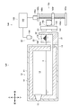
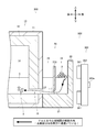
- the melting furnace 100 is a device that generates molten metal 3 by melting aluminum cutting waste 2, and includes a main body 10, a charging tank 20, and a stirring device 150.
- the aluminum cutting waste 2 is an embodiment of an object to be melted according to the present invention, and is an object to be melted by the melting furnace 100.
- the aluminum cutting waste 2 is made of an aluminum alloy.
- the shape of the aluminum cutting waste 2 is bowl-shaped (elongated shape), and the size of the aluminum cutting waste 2 is about 1 mm to 10 cm.
- the aluminum cutting waste 2 is generated by cutting a part (for example, an engine block) made of an aluminum alloy.
- the material which comprises the to-be-dissolved material which concerns on this invention is not limited to the aluminum alloy which is the material which comprises the aluminum cutting waste 2.
- FIG. Examples of the material constituting the material to be dissolved according to the present invention include various metal materials such as pure aluminum, aluminum alloy, pure magnesium, magnesium alloy, pure titanium, and titanium alloy.
- pure aluminum, aluminum alloy, pure magnesium, and magnesium alloy are non-magnetic when solid, have a relatively low melting point compared to other metal materials, have a relatively low specific gravity, and are liquids of molten metal. It is more preferable to apply the stirrer, the dissolution apparatus, and the dissolution method according to the present invention because they easily float on the surface and easily form a high melting point oxide film on the surface.
- the shape of the material to be melted according to the present invention is not limited to the shape of the aluminum cutting waste 2.
- the shape of the material to be dissolved according to the present invention may be other shapes such as a spherical shape or a lump shape.
- the size of the material to be melted according to the present invention is not limited to the size of the aluminum cutting waste 2.
- a material having a size of less than 1 mm such as a fine powder of an aluminum alloy or a material having a size exceeding 10 cm such as a cut piece of an aluminum alloy part is also included in the melted material according to the present invention.
- the molten metal 3 refers to a liquid obtained by melting the aluminum cutting waste 2.
- the molten metal which concerns on this invention should just be a liquid which consists of substantially the same material (in the case of an alloy, substantially the same composition) as a to-be-melted material. That is, the molten metal (initial molten metal) into which the material to be melted is introduced at the start of melting is different from the method for melting the material to be melted (for example, a method for melting an ingot made of substantially the same material as the material to be melted). ).
- the main body 10 maintains the temperature of the molten metal 3 at a temperature higher than the solidification temperature.
- the main body 10 includes a structure 11, a refractory / heat insulating material 12, and a burner 13.
- the structure 11 is a substantially rectangular parallelepiped box-shaped member.
- the fireproof and heat insulating material 12 is a member made of ceramics or the like, and covers the inner peripheral surface of the structure 11 by being fixed to the inner peripheral surface of the structure 11.
- a holding chamber 14 is formed inside the structure 11 as a space surrounded by the fireproof and heat insulating material 12, and a communication path 15 is formed at the lower part of the rear surface of the structure 11.
- the molten metal 3 is stored in the lower half of the holding chamber 14.
- the burner 13 is provided in the upper part of the inner peripheral surface in front of the structure 11 and raises the temperature of the air inside the holding chamber 14 and eventually the molten metal 3 (the molten metal 3 in contact with the air) stored in the lower half of the holding chamber 14. To do.
- the temperature of the molten metal 3 is raised by the burner 13, but the present invention is not limited to this, and the molten metal may be heated using another heat source (for example, an electric heater or the like).
- the charging tank 20 is a part for charging the aluminum cutting waste 2 in the melting furnace 100.
- the charging tank 20 is fixed to the rear end portion of the main body 10.
- the charging tank 20 includes a bottom floor 21 and side walls 22.
- the bottom floor 21 is a substantially rectangular plate-like portion in plan view that extends rearward from the rear end of the structure 11 in the charging tank 20.
- the side wall 22 is a plate-like portion erected along the left end portion, the rear end portion, and the right end portion of the bottom floor 21 in the charging tank 20.
- the left front end and the right front end of the side wall 22 extend to the rear left end and the rear right end of the structure 11, respectively.
- An input chamber 23 is formed as a space surrounded by the bottom floor 21, the side wall 22, and the rear surface of the structure 11 in the input tank 20.
- the molten metal 3 is stored in the lower half of the charging chamber 23.
- the holding chamber 14 and the charging chamber 23 are communicated with each other through a communication path 15, and the molten metal 3 can move between the holding chamber 14 and the charging chamber 23 through the communication path 15.
- the top surface of the charging tank 20 is open, and the aluminum cutting waste 2 is charged into the charging chamber 23 through the opening (more strictly speaking, a first molten metal rectifying member 170 and a second molten metal rectifying member described later in plan view). 180 and the portion surrounded by the side wall 22).
- the aluminum cutting waste 2 charged into the charging chamber 23 is heated in contact with the molten metal 3 stored in the lower half of the charging chamber 23 and melts when the temperature reaches the melting point or higher.
- the inner peripheral surface is the refractory / heat insulating material 12.
- Both “covered structure 11” and “input tank 20” correspond to an embodiment of the dissolution tank according to the present invention.
- the stirrer 150 is a first embodiment of the stirrer according to the present invention.
- the stirrer 150 agitates the molten metal 3 into which the aluminum cutting waste 2 is charged (the molten metal 3 stored in the lower half of the charging chamber 23), thereby producing aluminum. It is an apparatus that promotes dissolution of the cutting waste 2.
- the stirring device 150 includes a moving magnetic field generator 160, a first molten metal rectifying member 170, and a second molten metal rectifying member 180.
- the moving magnetic field generator 160 is an embodiment of the moving magnetic field device according to the present invention.
- ( ⁇ ) A magnetic field that moves downward along the rear side wall 22 and ( ⁇ ) an upward direction along the rear side wall 22. This is a device that generates a magnetic field that moves to the inside of the charging tank 20.
- the moving magnetic field generator 160 is disposed outside the charging tank 20 (in this embodiment, behind the charging tank 20).
- the moving magnetic field generation device 160 includes permanent magnets 161 and 161, a support member 162, a motor 163, a liquid level position detection device 164, a lifting device 165, and a control device 166.
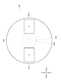
- the permanent magnets 161 and 161 are an embodiment of the permanent magnet according to the present invention, and are opposed to the rear side wall 22 as shown in FIGS.
- a “permanent magnet” refers to an object that can retain its properties as a magnet for a relatively long period of time even when no magnetic field or current is supplied from the outside.
- Specific examples of the permanent magnet according to the present invention include alnico magnet, KS steel, MK steel, ferrite magnet, samarium cobalt magnet, neodymium magnet and the like.
- the permanent magnets 161 and 161 are composed of neodymium magnets from the viewpoint of generating a strong magnetic force.
- the moving magnetic field generator 160 includes two permanent magnets 161 and 161, but the present invention is not limited to this, and the number of permanent magnets included in the moving magnetic field generator according to the present invention is as follows. It may be singular or plural.
- the support member 162 is an embodiment of the support member according to the present invention, and supports the permanent magnets 161 and 161.
- the support member 162 according to the present embodiment is a substantially disk-shaped member, and is disposed so that the disk surface thereof is parallel to the rear side wall 22.
- the permanent magnets 161 and 161 are fixed to the board surface of the support member 162 facing the rear side wall 22 at positions equidistant from the center of the board surface with the center of the board surface interposed therebetween.
- the motor 163 is an embodiment of the motor according to the present invention, and rotationally drives the support member 162 and eventually the permanent magnets 161 and 161 fixed to the support member 162.
- a rotation shaft 163 a of the motor 163 is fixed to the support member 162.
- the axis of the rotation shaft 163a and the center line of the support member 162 fixed to the rotation shaft 163a (line passing through the center of the pair of board surfaces of the support member 162) are in a straight line.
- the motor 163 of this embodiment is an electric motor
- the motor according to the present invention is not limited to this, and may be a motor that is driven to rotate by fluid pressure (for example, a hydraulic motor, a pneumatic motor, or the like). good.
- the rotating shaft 163a, the supporting member 162 fixed to the rotating shaft 163a, and the permanent magnets 161 and 161 fixed to the supporting member 162 rotate integrally (in this embodiment, the permanent magnet 161 and 161 rotate counterclockwise in rear view).
- the rear side wall 22 moves substantially downward along the rear side wall 22 into the charging tank 20 corresponding to the portion facing the left half of the support member 162.
- the charging tank 20 corresponding to a portion facing the right half of the support member 162 (that is, a position away from the magnetic field moving downward by a predetermined distance) on the side wall 22 on the rear side.
- a magnetic field that moves generally upward along the line will be generated.
- a flow (melt flow) of the molten metal 3 that circulates around an axis (in the present embodiment, the rotation shaft 163 a of the motor 163) that is substantially parallel to the liquid level of the molten metal 3 is generated in the molten metal 3.
- the aluminum cutting waste 2 moves on the flow of the molten metal 3 (melt flow), and the flow of the molten metal 3 generally downward (melt flow).
- the molten metal 3 enters the molten metal 3 (immersed in the molten metal 3) and receives heat from the molten metal 3 to melt.
- the molten metal 3 in the vicinity of the position where the aluminum cutting waste 2 is melted decreases due to melting of the aluminum cutting waste 2, the molten metal 3 is agitated by the flow of the molten metal 3 (melt flow).
- the temperature of 3 is kept substantially uniform.
- the liquid surface position detection device 164 is an embodiment of the liquid surface position detection device according to the present invention, and detects the position of the liquid surface of the molten metal 3. As shown in FIG. 1, the liquid level position detection device 164 is disposed above the charging tank 20 and thus above the liquid level of the molten metal stored in the charging chamber 23, and transmits ultrasonic waves toward the liquid level of the molten metal 3 ( Irradiation) and receiving the ultrasonic wave reflected by the liquid surface of the molten metal 3 and detecting the position of the liquid surface based on the speed of the ultrasonic wave and the time from transmission of the ultrasonic wave toward the liquid surface of the molten metal 3 until reception.
- the position (height) of the liquid surface of the molten metal 3 is detected by calculating the distance from the device 164 to the liquid surface of the molten metal 3.
- the liquid level position detection device according to the present invention is not limited to the configuration for detecting the position of the liquid level of the molten metal using ultrasonic waves, such as the liquid level position detection device 164 of the present embodiment. A configuration for detecting the position of the liquid level may also be used.
- the lifting device 165 is an embodiment of the lifting device according to the present invention, and supports the motor 163 so that the motor 163 can be raised and lowered. As shown in FIG. 1, the lifting device 165 includes a base member 165a, a support member 165b, a top member 165c, a ball screw 165d, a servo motor 165e, and a slide member 165f.
- the base member 165a is a plate-like member that forms the lower part of the lifting device 165.
- the base member 165a is fixed to the floor surface, the ground, or other structures.
- the support member 165b is a substantially cylindrical member.
- One end (lower end) of the column member 165b is fixed to the base member 165a.
- the longitudinal direction of the column member 165b coincides with the vertical direction.
- the top member 165 c is a plate-like member that forms the upper part of the lifting device 165.
- the top member 165c is fixed to the other end (upper end) of the support member 165b.
- the ball screw 165d is a substantially cylindrical member having a male screw formed on the outer peripheral surface.
- the servo motor 165e is an electric motor capable of adjusting the rotation direction and rotation amount (rotation angle) of the rotation shaft.
- the servo motor 165e is fixed to the top member 165c.
- the rotation shaft of the servo motor 165e is fixed to the upper end of the ball screw 165d.
- the slide member 165f is a plate-like member. A through-hole penetrating the upper and lower plate surfaces is formed in the slide member 165f, and a column member 165b is slidably inserted into the through-hole.
- the slide member 165f is formed with a screw hole penetrating the upper and lower plate surfaces, and a ball screw 165d is screwed into the screw hole.
- the motor 163 is fixed to the plate surface (upper surface) above the slide member 165f.
- the rotation shaft of the servo motor 165e and the ball screw 165d rotate integrally, and the slide member 165f screwed to the ball screw 165d moves (slides) in the vertical direction along the column member 165b. .
- the rotation direction and the rotation amount (rotation angle) of the rotation shaft of the servo motor 165e By adjusting the rotation direction and the rotation amount (rotation angle) of the rotation shaft of the servo motor 165e, the lifting / lowering amount of the combination of the slide member 165f, the motor 163, the support member 162, and the permanent magnets 161 and 161 is adjusted (vertical direction). It is possible to adjust the movement amount.
- the control device 166 is an embodiment of the control device according to the present invention, and is used to raise or lower the motor 163 to the lifting device 165 based on the position of the liquid level of the molten metal 3 detected by the liquid level position detection device 164. By transmitting this signal (hereinafter referred to as “control signal”), the relative position of the motor 163 in the vertical direction with respect to the liquid level of the molten metal 3 is controlled.
- the control device 166 can store various programs and the like, can develop these programs and the like, can perform predetermined calculations according to these programs and the like, and stores the results of the calculations and the like And the result of the calculation can be output to the outside.
- the control device 166 has a configuration in which a CPU (Central Processing Unit), a ROM (Read-Only Memory), a RAM (Random Access Memory), an HDD (Hard Disk Drive), and the like are connected to each other via a bus. Alternatively, a configuration including a one-chip LSI (Large Scale Integration) or the like may be used.
- the control device 166 in the present embodiment is a dedicated product, it can also be achieved by appropriately storing a program or the like in a commercially available personal computer or workstation.
- the control device 166 is connected to the liquid surface position detection device 164, and can acquire information (signal) related to the liquid surface position of the molten metal 3 detected by the liquid surface position detection device 164.
- the control device 166 is connected to an elevating device 165, more specifically, a servo motor 165e, and information related to the rotation amount (rotation angle) of the servo motor 165e to the servo motor 165e, and thus the position (height) of the rotation shaft 163a of the motor 163. It is possible to acquire information (signal) according to the above. Further, the control device 166 can transmit a signal (corresponding to a control signal) for instructing the rotation direction, rotation speed, and rotation amount (rotation angle) of the rotation shaft of the servo motor 165e to the servo motor 165e. .
- the control device 166 includes the “information related to the position of the liquid surface of the molten metal 3” detected by the liquid level position detection device 164 and the “information related to the position of the rotating shaft 163a of the motor 163” acquired from the servo motor 165e. Based on this, the relative position of the rotating shaft 163a of the motor 163 with respect to the liquid level of the molten metal 3 is calculated.
- the control device 166 stores in advance the “permissible range of the relative position of the rotating shaft 163 a of the motor 163 with respect to the liquid level of the molten metal 3”, and “relative to the rotational axis 163 a of the motor 163 with respect to the liquid level of the molten metal 3.
- the “position allowable range” is compared with the “calculation result of the relative position of the rotating shaft 163a of the motor 163 with respect to the liquid level of the molten metal 3”.
- the “calculation result of the relative position of the rotating shaft 163a of the motor 163 with respect to the liquid surface of the molten metal 3” is “the allowable range of the relative position of the rotating shaft 163a of the motor 163 with respect to the liquid surface of the molten metal 3”.
- the calculation result of the relative position of the rotating shaft 163a of the motor 163 with respect to the liquid level of the molten metal 3) is included in “the allowable range of the relative position of the rotating shaft 163a of the motor 163 with respect to the liquid level of the molten metal 3”.
- control device 166 does not transmit a control signal to the servo motor 165e and holds the position (height) of the rotating shaft 163a of the motor 163.
- the “calculation result of the relative position of the rotating shaft 163a of the motor 163 with respect to the liquid level of the molten metal 3” is “allowable relative position of the rotating shaft 163a of the motor 163 with respect to the liquid level of the molten metal 3”. “The calculation result of the relative position of the rotating shaft 163a of the motor 163 with respect to the liquid level of the molten metal 3” is not included in the “range”. If it is smaller than the lower limit value of the “range” or larger than the upper limit value), the control device 166 transmits a control signal to the servo motor 165e to adjust the position (height) of the rotating shaft 163a of the motor 163.
- the “calculation result of the relative position of the rotating shaft 163a of the motor 163 with respect to the liquid level of the molten metal 3” is “the allowable range of the relative position of the rotating shaft 163a of the motor 163 with respect to the liquid level of the molten metal 3”.
- the control device 166 transmits a control signal for increasing the position (height) of the rotating shaft 163a of the motor 163 to the servo motor 165e.
- the servo motor 165e that has received the control signal is rotationally driven in a direction to raise the position (height) of the rotating shaft 163a of the motor 163.
- the “calculation result of the relative position of the rotating shaft 163a of the motor 163 with respect to the liquid level of the molten metal 3” is the upper limit value of “the allowable range of the relative position of the rotating shaft 163a of the motor 163 with respect to the liquid level of the molten metal 3”. If larger, the control device 166 sends a control signal for lowering the position (height) of the rotating shaft 163a of the motor 163 to the servo motor 165e. The servo motor 165e that has received the control signal is rotationally driven in a direction in which the position (height) of the rotating shaft 163a of the motor 163 is lowered.
- the relative position of the rotation shaft 163a of the motor 163 with respect to the liquid level of the molten metal 3 is set so that the position of the rotation shaft 163a of the motor 163 is lower than the liquid level of the molten metal 3 by a predetermined distance.
- a “range” is defined.
- the control device 166 holds the lifting device 165 so as to hold the position of the rotating shaft 163a of the motor 163 at a position lower by a predetermined distance than the liquid level position of the molten metal 3 detected by the liquid level position detection device 164.
- a control signal is transmitted to.
- the specific value of “the allowable range of the relative position of the rotating shaft 163a of the motor 163 with respect to the liquid surface of the molten metal 3” is the composition (material) of the molten metal 3 (aluminum cutting waste 2), the temperature of the molten metal 3, Various factors such as the amount (volume) of the molten metal 3, the shape of the charging tank 20 (shape of the charging chamber 23), the magnetic force of the permanent magnets 161 and 161, and the rotational speed of the motor 163 (rotational speed of the permanent magnets 161 and 161) It is set after comprehensive consideration.
- the first molten metal rectifying member 170 is an embodiment of the first molten metal rectifying member according to the present invention, and is a member that promotes melting of the aluminum cutting waste 2 by adjusting the flow of the molten metal 3.
- the first molten metal rectifying member 170 of the present embodiment is a plate-shaped member having at least a surface made of a refractory material such as ceramics, and has a first molten metal rectifying surface 171.
- the inside of the first molten metal rectifying member 170 may be a heat resistant material such as metal.
- the first molten metal rectifying member 170 is located at the position corresponding to “the magnetic field moving downward along the side wall 22 of the charging tank 20” generated by the moving magnetic field generator 160 inside the charging tank 20 (inside the charging chamber 23). In the embodiment, it is disposed inside the charging tank 20 at a position slightly on the left side of the magnetic field moving substantially downward), and the rear end portion of the first molten metal rectifying member 170 is the side wall 22 on the rear side of the charging tank 20. Fixed to. An upper end portion of the first molten metal rectifying member 170 fixed to the rear side wall 22 of the charging tank 20 is disposed above the liquid surface of the molten metal 3, and a lower end portion of the first molten metal rectifying member 170 and a bottom of the charging tank 20.
- the molten metal 3 positioned on the left side of the first molten metal rectifying member 170 and the molten metal 3 positioned on the right side of the first molten metal rectifying member 170 in plan view are the lower end portion of the first molten metal rectifying member 170 and the bottom floor of the charging tank 20. Are connected through a gap formed between them (movable to each other). Further, the first molten metal rectifying surface 171 of the first molten metal rectifying member 170 disposed in the charging tank 20 is directed to the right side and is substantially perpendicular to the side wall 22 and the horizontal plane of the charging tank 20.
- a moving magnetic field (a magnetic field that moves generally downward along the side wall 22 on the rear side of the charging tank 20 and a magnetic field that moves generally upward on the side wall 22 on the rear side of the charging tank 20).
- the flow of the molten metal 3 generated by the gas is generally leftward in the vicinity of the liquid surface of the molten metal 3 (strictly, the front left), and when reaching the first molten metal rectifying surface 171 of the first molten metal rectifying member 170, the first molten metal rectifying surface. 171 is corrected downward along 171. That is, by disposing the first molten metal rectifying member 170, it is possible to change the flow in the vicinity of the liquid surface of the molten metal 3 from substantially left to substantially downward. Therefore, the downward flow of the molten metal 3 can be generated more strongly than when the first molten metal rectifying member 170 is not disposed.
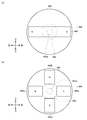
- the first molten metal rectifying surface 171 has a shape in which a central portion is recessed in a plan view.
- the first molten metal rectifying surface 171 having such a shape has the following advantages. That is, the flow of the molten metal 3 in the vicinity of the liquid surface of the molten metal 3 is strictly leftward, that is, not in a direction parallel to the rear side wall 22 in a plan view, but gradually away from the rear side wall 22 (this embodiment). Then left front).
- the shape of the first molten metal rectifying surface 171 By making the shape of the first molten metal rectifying surface 171 into a shape in which the central portion is depressed in a plan view, the flow of the molten metal 3 in the vicinity of the liquid surface of the molten metal 3 approaches the rear side wall 22 in the plan view in the plan view. Thus, it is possible to change the downward flow of the molten metal 3 and to generate a downward flow of the molten metal 3 more strongly.
- the second molten metal rectifying member 180 is an embodiment of the second molten metal rectifying member according to the present invention, and is a member that promotes melting of the aluminum cutting waste 2 by adjusting the flow of the molten metal 3.
- the second molten metal rectifying member 180 of the present embodiment is a plate-shaped member having at least a surface made of a refractory material such as ceramics, and has a second molten metal rectifying surface 181.
- the inside of the second molten metal rectifying member 180 may be a heat resistant material such as metal.
- the second molten metal rectifying member 180 is disposed at a position on the opposite side of the moving magnetic field generator 160 with the side wall 22 on the rear side of the charging tank 20 inside the charging tank 20 (inside the charging chamber 23).
- the left end portion of the rectifying member 180 is fixed to the front end portion of the first molten metal rectifying member 170, and the right end portion of the second molten metal rectifying member 180 is fixed to the right side wall 22 of the charging tank 20.
- the upper end portion of the second molten metal rectifying member 180 fixed to the right side wall 22 of the charging tank 20 is disposed above the liquid surface of the molten metal 3, and the lower end portion of the second molten metal rectifying member 180 and the bottom floor of the charging tank 20.
- a gap of a predetermined size is formed between the two.
- the molten metal 3 positioned on the front side of the second molten metal rectifying member 180 and the molten metal 3 positioned on the rear side of the second molten metal rectifying member 180 in plan view are the bottom end of the second molten metal rectifying member 180 and the bottom of the charging tank 20. They are connected through a gap formed between the floor 21 (movable to each other). Further, the second molten metal rectifying surface 181 of the second molten metal rectifying member 180 disposed inside the charging tank 20 is directed rearward (facing the side wall 22 on the rear side of the charging tank 20), and the rear side of the charging tank 20. Is substantially parallel to the side wall 22 of
- a moving magnetic field (a magnetic field that moves generally downward along the side wall 22 on the rear side of the charging tank 20 and a magnetic field that moves generally upward on the side wall 22 on the rear side of the charging tank 20).
- the flow of the molten metal 3 generated by the above is directed leftward in the vicinity of the liquid surface of the molten metal 3, but when the flow of the molten metal reaches the second molten metal rectifying surface 181 of the second molten metal rectifying member 180, the second molten metal rectifying surface 181.
- the leftward flow of the molten metal 3 can be generated more strongly than the case where the second molten metal rectifying member 180 is not disposed, and as a result, the downward flow of the molten metal 3 can be generated more strongly.
- the stirring device 150 is a device that promotes melting of the aluminum cutting waste 2 by stirring the molten metal 3 into which the aluminum cutting waste 2 has been charged, and is provided outside the charging tank 20 in which the molten metal 3 is stored.
- a moving magnetic field generator 160 that generates a magnetic field that is disposed and moves downward along the side wall 22 on the rear side of the charging tank 20 is provided.
- the aluminum cutting waste 2 introduced into the molten metal 3 rides on the downward flow of the molten metal 3 (melt flow) generated by a magnetic field moving downward along the rear side wall 22. Therefore, it is possible to promote the dissolution of the aluminum cutting waste 2 (the aluminum cutting waste 2 is efficiently dissolved).
- the stirring device 150 can be provided side by side without adding a large modification to the existing melting device, and can be easily applied to the existing melting device.
- the moving magnetic field generator 160 is disposed at a position facing the rear side wall 22 of the charging tank 20, but the stirring device according to the present invention is not limited to this.
- the moving magnetic field generator 160 may be disposed at a position facing the left side wall 22 of the charging tank 20, or at a position facing the right side wall 22 (not shown). May be.
- the moving magnetic field generator 160 of the agitating device 150 is not only a magnetic field that moves downward along the rear side wall 22 of the charging tank 20 but also a charging tank at a position away from the magnetic field that moves downward by a predetermined distance.
- a magnetic field that moves upward along the side wall 22 on the rear side of the 20 is generated inside the charging tank 20.
- the moving magnetic field generator 160 of the stirring device 150 rotates the permanent magnets 161 and 161 facing the rear side wall 22 of the charging tank 20, the support member 162 that supports the permanent magnets 161 and 161, and the support member 162.
- a motor 163 to be driven With this configuration, it is possible to generate a magnetic field that moves downward along the side wall 22 on the rear side of the charging tank 20 with a simple and low power consumption structure.
- the moving magnetic field generator 160 of the stirring device 150 includes a liquid level position detection device 164 that detects the position of the liquid level of the molten metal 3, an elevating device 165 that supports the motor 163 so that it can be raised and lowered, and a liquid level position detection.
- a liquid level position detection device 164 that detects the position of the liquid level of the molten metal 3
- an elevating device 165 that supports the motor 163 so that it can be raised and lowered
- a liquid level position detection By transmitting a signal for raising or lowering the motor 163 to the lifting / lowering device 165 based on the position of the liquid level of the molten metal 3 detected by the apparatus 164, the motor 163 is relatively relative to the liquid level of the molten metal 3.
- a control device 166 for controlling the correct position.
- control device 166 of the moving magnetic field generation device 160 of the stirring device 150 lowers the position of the rotating shaft 163a of the motor 163 by a predetermined distance with respect to the position of the liquid level of the molten metal 3 detected by the liquid level position detection device 164.
- a signal to raise or lower the motor 163 is transmitted to the lifting device 165 so as to hold the position.
- the moving magnetic field generator 160 includes a liquid level position detection device 164, an elevating device 165, and a control device 166, but the position of the liquid level of the molten metal 3 in terms of the apparatus configuration of the melting furnace 100 or the operation of the melting furnace 100.
- the liquid level position detection device 164, the lifting device 165, and the control device 166 can be omitted.
- the rotating shaft 163a of the motor 163 is more than the liquid surface of the molten metal 3 from the viewpoint of more efficiently applying the moving magnetic field to the molten metal 3. It is preferable to fix the motor 163 so as to be disposed at a position lower by a predetermined distance.
- the stirring device 150 is disposed at a position corresponding to a magnetic field that moves downward along the side wall 22 on the rear side of the charging tank 20 generated by the moving magnetic field generator 160 inside the charging tank 20.
- a first molten metal rectifying member 170 having a first molten metal rectifying surface 171 perpendicular to the rear side wall 22 and a horizontal plane is provided.
- straightening member 170 of the stirring apparatus 150 has a shape where the center part was depressed in planar view.
- straightening surface 171 in this embodiment is comprised by a curved surface
- straightening surface which concerns on this invention is not limited to this.
- the first molten metal rectifying surface 171 shown in FIGS. 6A and 6B may be “a combination of a plurality of planes”, or the first molten metal rectifying shown in FIG. 6C.
- the surface 171 may be “a combination of a plurality of curved surfaces and a plane”.
- the stirring device 150 is disposed at a position on the opposite side of the moving magnetic field generator 160 with the side wall 22 on the rear side of the charging tank 20 inside the charging tank 20.
- a second molten metal rectifying member 180 having a parallel second molten metal rectifying surface 181 is provided.
- the stirring device 150 of the present embodiment includes the first molten metal rectifying member 170 and the second molten metal rectifying member 180.
- the first molten metal rectifying member 170 and the second molten metal rectifying member 180 are used depending on the shape of the charging tank 20, the first molten metal rectifying member 170 and the second molten metal rectifying member 180 are used. Either one or both of them can be omitted.
- the right and left side walls 22 of the charging tank 20 can perform the same function as the first molten metal rectifying member 170.
- the rectifying member 170 can be omitted.
- the rear surface of the structure 11 of the main body 10 can perform the same function as the second molten metal rectifying member 180, and the second molten metal rectifying member 180 is omitted. It is possible. Further, as shown in FIG. 3, the upward flow of the molten metal 3 can be promoted by rounding the corner portion between the bottom floor 21 and the side wall 22 of the charging tank 20.
- first molten metal rectifying member 170 and the second molten metal rectifying member 180 of the present embodiment are fixed to the charging tank 20, they may be moved up and down according to the position (height) of the liquid surface of the molten metal 3.
- the melting furnace 100 is a melting device that melts the aluminum cutting waste 2 by putting the aluminum cutting waste 2 into the molten metal 3 stored in the charging tank 20, and includes a stirring device 150.
- the aluminum cutting waste 2 thrown into the molten metal 3 is made into the flow (melt flow) of the downward molten metal 3 which generate
- the aluminum cutting waste 2 can be melt
- the stirring device 150 is disposed behind the charging tank 20, but may be disposed on the left side of the charging tank 20 or on the right side of the charging tank 20.
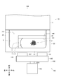
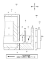
- the melting furnace 200 which is 2nd embodiment of the melting apparatus which concerns on this invention using FIG.7 and FIG.8 is demonstrated.
- the same member number is attached
- the melting furnace 200 includes a main body 10, a charging tank 20, and a stirring device 250.
- the stirrer 250 is a second embodiment of the stirrer according to the present invention.
- the stirrer 250 agitates the molten metal 3 (the molten metal 3 stored in the lower half portion of the charging chamber 23) into which the aluminum cutting waste 2 has been charged. It is an apparatus that promotes dissolution of the cutting waste 2.
- the stirring device 250 includes a moving magnetic field generator 260, a first molten metal rectifying member 270, and a second molten metal rectifying member 280.
- the moving magnetic field generator 260 is an embodiment of the moving magnetic field device according to the present invention, and ( ⁇ ) a magnetic field that moves downward along the rear side wall 22 and ( ⁇ ) upwards along the rear side wall 22. This is a device that generates a magnetic field that moves to the inside of the charging tank 20.
- the moving magnetic field generator 260 includes electromagnetic coils 261, 261, and a power supply device 262.
- the electromagnetic coils 261, 261... are one embodiment of a plurality of electromagnetic coils according to the present invention, and generate a magnetic field around when energized.
- the electromagnetic coils 261, 261,... are arranged in a substantially ring shape along the side wall 22 on the rear side of the charging tank 20.
- the power supply device 262 is an embodiment of the power supply device according to the present invention, and sequentially supplies power to the electromagnetic coils 261, 261, ... (in this embodiment, counterclockwise when viewed from the rear).
- the power supply device 262 sequentially supplies power to the electromagnetic coils 261, 261,... Counterclockwise as viewed from the rear, so that the electromagnetic coils 261 supplied with power are sequentially excited.
- a magnetic field that moves in a substantially ring shape (similar to the arrangement of the electromagnetic coils 261, 261,...) Along the rear side wall 22 of the charging tank 20 is generated inside the charging tank 20.
- the left half of the rear view shows a magnetic field that moves substantially downward along the rear side wall 22 of the charging tank 20
- the right half of the rear view shows a side wall 22 of the rear of the charging tank 20.
- the stirring device 250 of the melting furnace 200 sequentially supplies power to the electromagnetic coils 261, 261, and the electromagnetic coils 261, 261, which are arranged along the rear side wall 22 of the charging tank 20.
- a power supply device 262 to supply.
- the shape of the locus of the moving magnetic field is not limited to a circle as in the stirring device 150 shown in FIG. It is possible to adopt various shapes such as a linear shape and an elliptical shape according to the above.
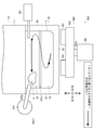
- One embodiment of the melting method according to the present invention is a method of melting aluminum cutting waste 2 using a melting furnace 100 (see FIG. 1), and includes a charging step S1100 and a stirring step S1200.
- the charging step S1100 is a step of charging the aluminum cutting waste 2 into the molten metal 3 stored in the charging tank 20.
- the process proceeds to the stirring step S1200.
- the stirring step S1200 is a step of stirring the molten metal 3 by generating a magnetic field that moves downward along the side wall 22 on the rear side of the charging tank 20 in the charging tank 20.
- the stirring step S1200 when electric power is supplied to the motor 163 of the stirring device 150, the rotating shaft 163a, the supporting member 162 fixed to the rotating shaft 163a, and the permanent magnets 161 and 161 fixed to the supporting member 162 rotate integrally. To do.
- the permanent magnets 161 and 161 are rotated, the magnetic field that moves substantially downward along the side wall 22 on the rear side of the charging tank 20 and the rear of the charging tank 20 at a position that is a predetermined distance away from the magnetic field that moves substantially downward.
- a magnetic field that moves generally upward along the side wall 22 on the side is generated inside the charging tank 20.
- a generally downward flow of the molten metal 3 is generated in the molten metal 3.
- the aluminum cutting waste 2 charged into the molten metal 3 in the charging step S1100 moves along the flow (melt flow), sneaks into the molten metal 3 (immersed in the molten metal 3), and melts by receiving heat from the molten metal 3. .
- one embodiment of the melting method according to the present invention is based on the charging step S1100 in which the aluminum cutting waste 2 is charged into the molten metal 3 stored in the charging tank 20 and the side wall 22 on the rear side of the charging tank 20. And a stirring step S1200 for stirring the molten metal 3 by generating a magnetic field that moves downward in the charging tank 20.
- a stirring step S1200 for stirring the molten metal 3 by generating a magnetic field that moves downward in the charging tank 20 By configuring in this way, the aluminum cutting waste 2 put into the molten metal 3 is immersed in the molten metal 3 on the flow of the downward molten metal 3 (melt flow) generated by the magnetic field moving downward along the side wall 22. Therefore, it is possible to dissolve the aluminum cutting waste 2 efficiently.
- the charging tank 20 is placed at a position away from the magnetic field that moves substantially downward along the side wall 22 on the rear side of the charging tank 20 by a predetermined distance.
- a magnetic field that moves generally upward along the rear side wall 22 is generated inside the charging tank 20.
- the stirring step S1200 in the stirring step S1200, the permanent magnets 161 and 161 facing the rear side wall 22 of the charging tank 20 and the support member 162 that supports the permanent magnets 161 and 161 are used. And a motor 163 that rotationally drives the support member 162 and moves downward along the side wall 22 on the rear side of the charging tank 20 by using the moving magnetic field generator 160 disposed outside the charging tank 20. To generate a magnetic field. With this configuration, it is possible to generate a magnetic field that moves downward along the side wall 22 of the charging tank 20 with a simple and low power consumption structure.
- the apparatus for generating a magnetic field downward along the side wall of the dissolution tank in the agitation process of the dissolution method according to the present invention is not limited to the moving magnetic field generation apparatus 160 of the present embodiment.
- the first molten metal rectifying member 170 having the first molten metal rectifying surface 171 perpendicular to the rear side wall 22 and the horizontal surface of the charging tank 20 is provided. Is disposed at a position corresponding to a magnetic field that moves downward along the side wall 22 on the rear side of the charging tank 20 inside the charging tank 20.
- the first molten metal rectifying surface 171 of the first molten metal rectifying member 170 disposed in the charging tank 20 in the stirring step S1200 has a depressed central portion in plan view. Has a shape.
- the second molten metal rectifying member 180 having the second molten metal rectifying surface 181 parallel to the side wall 22 on the rear side of the charged tank 20 is added to the charged tank. 20 and disposed on the opposite side of the moving magnetic field generator 160 across the side wall 22 on the rear side of the charging tank 20.
- the process proceeds to the stirring process S1200 after the charging process S1100 is completed, but the present invention is not limited to this. That is, the charging step and the stirring step may be performed in parallel (simultaneously).
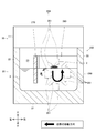
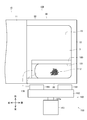
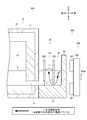
- the melting furnace 300 which is 3rd embodiment of the melting apparatus which concerns on this invention using FIGS. 11-15 is demonstrated.
- the melting furnace 300 is an apparatus that generates the molten metal 3 by melting the aluminum cutting waste 2.
- the melting furnace 300 includes a main body 10, a charging tank 20, and a stirring device 350.
- the stirrer 350 is a third embodiment of the stirrer according to the present invention.
- the stirrer 350 agitates the molten metal 3 (the molten metal 3 stored in the lower half of the charging chamber 23) into which the aluminum cutting waste 2 has been charged. It is a device that promotes dissolution of the cutting waste 2.
- the stirring device 350 includes a moving magnetic field generator 360 and a closing / floating partition member 370.
- the moving magnetic field generator 360 is an embodiment of the moving magnetic field device according to the present invention.
- ( ⁇ ) A magnetic field that moves downward along the rear side wall 22 and ( ⁇ ) an upward direction along the rear side wall 22. This is a device that generates a magnetic field that moves to the inside of the charging tank 20.
- the moving magnetic field generator 360 is disposed outside the charging tank 20 (in this embodiment, behind the charging tank 20).
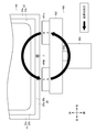
- the moving magnetic field generator 360 includes permanent magnets 361 and 361, a support member 362, a motor 363 having a rotating shaft 363a, and a fixed member 364.
- the basic structure of the permanent magnets 361 and 361, the support member 362, and the motor 363 having the rotating shaft 363a are the permanent magnets 161 and 161 and the support member 162 in FIG. , And the motor 163 having the rotating shaft 163a, the description thereof will be omitted.
- the fixing member 364 is a member that fixes the motor 363 to a predetermined position with respect to the charging tank 20.
- the fixing member 364 is fixed to a structure or the like (not shown).
- the input / floating partition member 370 shown in FIGS. 11, 12 and 13 is an embodiment of the input / floating partition member according to the present invention.
- the input / floating partition member 370 is a plate-like member having at least a surface as a refractory material such as ceramics.
- the inside of the charging / floating partition member 370 may be a heat-resistant material such as metal.
- the input / floating partition member 370 is disposed inside the input tank 20 (inside the input chamber 23). More specifically, the input / floating partition member 370 is disposed at a position opposite to the moving magnetic field generator 360 across the side wall 22 on the rear side of the input tank 20.
- the left end portion of the charging / floating partition member 370 is fixed to the middle portion in the front-rear direction of the left side wall 22 of the charging tank 20, and the right end portion of the charging / floating partition member 370 is the right side of the charging tank 20.
- the side wall 22 is fixed to a midway portion in the front-rear direction.
- the charging / floating partition member 370 partitions (partitions) the space inside the charging tank 20 into two spaces of the charging / dissolving chamber 24 and the floating substance recovery chamber 25.
- the charging / dissolving chamber 24 is a space closer to the moving magnetic field generator 360 out of the two spaces partitioned by the charging / floating partition member 370.
- the charging / melting chamber 24 is a space for charging the aluminum cutting waste 2 with the molten metal 3.
- the aluminum cutting waste 2 is introduced into the molten metal 3 from the portion corresponding to the charging / melting chamber 24 in the liquid surface of the molten metal 3.
- the floating substance recovery chamber 25 is a space farther from the moving magnetic field generator 360 out of the two spaces defined by the charging / floating partition member 370, and is just between the charging / dissolving chamber 24 and the holding chamber 14 in the melting tank. It is a space (intermediate chamber) provided in the middle.
- the floating material collection chamber 25 is a space for collecting Noro 4 (see FIGS. 14 and 15) generated by melting the aluminum cutting waste 2 (dissolving by putting the aluminum cutting waste 2 into the molten metal 3). .
- Noro 4 has various foreign matters mixed in the aluminum cutting waste 2 introduced into the molten metal 3, the surface of the aluminum cutting waste 2 oxidized (oil, paint, combustible, etc.), the surface of the aluminum cutting waste 2 is Oxidized, non-metallic inclusions, or a mixture (aggregate) thereof, etc., which can float on the molten metal 3 because the density (strictly speaking, bulk density) is lower than that of the molten metal 3. .
- Noro 4 is an embodiment of the suspended matter according to the present invention.
- the upper end portion of the charging / floating partition member 370 is disposed at a position above the liquid level of the molten metal 3. Further, a gap of a predetermined size (L1 in FIG. 13) is formed between the lower end of the charging / floating partition member 370 and the bottom floor 21 of the charging tank 20, and the charging / dissolving chamber 24 and the floating substance recovery are formed.
- the chambers 25 communicate with each other in the lower part of these spaces.
- the charging / floating partition member 370 moves between the charging / dissolving chamber 24 and the floating substance recovery chamber 25 in a portion where the molten metal 3 is close to the liquid surface (portion close to the liquid surface of the molten metal 3). Regulate (the molten metal 3 cannot move between the charging / dissolving chamber 24 and the suspended matter recovery chamber 25 at a portion close to the liquid surface).
- the charging / floating partition member 370 is disposed between the charging / dissolving chamber 24 and the floating material recovery chamber 25 (the charging / floating partition member) in a portion where the molten metal 3 is far from the liquid surface (a portion closer to the bottom floor 21). Allowing movement relative to each other (through the gap between 370 and the bottom floor 21).
- the part which comprises the rear surface of the structure 11 is arrange
- the portion forming the rear surface of the structure 11 is disposed at a position farther from the moving magnetic field generator 360 than the input / floating partition member 370.
- the portion constituting the rear surface of the structure 11 is a “portion farther from the moving magnetic field generator 360 than the input / floating partition member 370 in the space inside the dissolution tank of the present embodiment”, the suspended matter recovery chamber 25 and the holding chamber 14. Is divided into two spaces.
- a communication path 15 is formed below the lower end of the portion forming the rear surface of the structure 11 (lower rear surface of the structure 11), and the suspended matter collection chamber 25 and the holding chamber 14 communicate with each other in the lower portion of these spaces.
- the suspended matter recovery chamber 25 is a space closer to the moving magnetic field generator 360 out of two spaces partitioned with the portion forming the rear surface of the structure 11 as a boundary.
- the holding chamber 14 is a space farther from the moving magnetic field generator 360 among the two spaces defined by the portion constituting the rear surface of the structure 11, and the molten metal 3 is taken out from the holding chamber 14 (recovery). ) Therefore, the holding chamber 14 corresponds to one embodiment of the molten metal recovery chamber according to the present invention, and the portion forming the rear surface of the structure 11 corresponds to one embodiment of the floating / molten metal partitioning member according to the present invention.
- the support member 362 By supplying electric power to the motor 363 of the moving magnetic field generator 360, the support member 362 (and thus the permanent magnets 361 and 361) rotates counterclockwise in the rear view (back view). Therefore, in the molten metal 3 inside the charging tank 20 (the charging / melting chamber 24 and the floating substance recovery chamber 25), a magnetic field that moves counterclockwise in the rear view is generated as in the melting furnace 100 shown in FIG. Along with the moving magnetic field, a “counterclockwise spiral flow in the rear view” is generated in the molten metal 3.
- the aluminum cutting waste 2 introduced into the liquid surface of the molten metal 3 in the charging / melting chamber 24 is wound into the molten metal 3 along the flow inside the molten metal 3.
- the aluminum cutting waste 2 caught in the molten metal 3 is melted while moving forward in the molten metal 3 in the charging / melting chamber 24 while turning counterclockwise in a rear view.
- the undissolved aluminum cutting waste 2 moves from the charging / dissolving chamber 24 to the suspended matter recovery chamber 25 through a gap between the lower end of the charging / floating partition member 370 and the bottom floor 21 of the charging tank 20. .
- the magnetic field that moves counterclockwise in the rear view generated in the molten metal 3 becomes weaker as the distance from the permanent magnets 361 and 361 increases.
- the charging / dissolving chamber 24 and the suspended matter recovery chamber 25 are partitioned by the charging / floating partition member 370 at a portion close to the liquid level of the molten metal 3, it is generated in the molten metal 3 inside the charging / melting chamber 24.
- the “counterclockwise spiral flow in the rear view” is blocked to some extent by the input / floating partition member 370.
- the “counterclockwise spiral flow in the rear view” generated in the molten metal 3 in the floating substance recovery chamber 25 is generated in the “counterclockwise in the rear view” generated in the molten metal 3 in the charging / dissolving chamber 24. Although it is weaker than the “spiral flow”, it is spiral to a certain extent, but the flow is generally gentle forward. Moreover, since the density of the undissolved aluminum cutting waste 2 and the density of the molten metal 3 are substantially the same, the buoyancy which the undissolved aluminum cutting waste 2 receives from the molten metal 3 and the gravity acting on the undissolved aluminum cutting waste 2 ( The weight is almost balanced.
- the undissolved aluminum cutting waste 2 that has moved into the suspended matter recovery chamber 25 through the gap between the lower end of the input / floating partition member 370 and the bottom floor 21 of the input tank 20 is greatly increased by buoyancy. Without being lifted upward, it will be dissolved while slowly moving forward.
- the undissolved aluminum cutting waste 2 moves from the suspended matter recovery chamber 25 to the holding chamber 14 through the communication path 15. Since the holding chamber 14 is further away from the permanent magnets 361 and 361 than the suspended matter collection chamber 25, the molten metal 3 inside the charging / dissolving chamber 24 has a “counterclockwise spiral flow in the rear view”. It hardly occurs. Of the aluminum cutting scraps 2 put on the liquid surface of the molten metal 3 in the charging / melting chamber 24, those that have moved to the holding chamber 14 without being melted receive heat from the molten metal 3 inside the holding chamber 14, Will be dissolved.
- the aluminum cutting waste 2 charged on the surface of the molten metal 3 in the charging / dissolving chamber 24 is generated in the molten metal 3 by the moving magnetic field generator 360 "a spiral flow counterclockwise in a rear view. It is dissolved in the process of moving along. Further, the aluminum cutting waste 2 moves in the order of the liquid level of the molten metal 3 in the charging / melting chamber 24 ⁇ the lower part of the molten metal 3 in the charging / melting chamber 24 ⁇ the lower part of the molten metal 3 in the floating substance recovery chamber 25 ⁇ It does not move to the vicinity of the liquid level of the molten metal 3 in the suspended matter recovery chamber 25.
- Noro 4 generated when the aluminum cutting waste 2 is introduced into the liquid surface of the molten metal 3 in the charging / melting chamber 24 is wound into the molten metal 3 along the flow inside the molten metal 3.
- the roll 4 entrained in the molten metal 3 moves forward in the molten metal 3 in the charging / melting chamber 24 while turning counterclockwise in a rear view.
- Noro 4 moves from the charging / dissolving chamber 24 to the floating substance recovery chamber 25 through a gap between the lower end of the charging / floating partition member 370 and the bottom floor 21 of the charging tank 20.
- the buoyancy that the Noro 4 receives from the molten metal 3 is greater than the gravity (self-weight) acting on the Noro 4. Therefore, the noro 4 that has moved into the floating substance collection chamber 25 through the gap between the lower end portion of the charging / floating partition member 370 and the bottom floor 21 of the charging tank 20 is located inside the floating substance collection chamber 25. It deviates from the flow generated in the molten metal 3 (although it is spiral to some extent, the flow is generally gently forward), and floats to the right half of the liquid level of the molten metal 3 in the suspended matter recovery chamber 25 by buoyancy.
- the slag 4 that has floated to the right half of the liquid level of the molten metal 3 in the floating substance recovery chamber 25 gently floats along the flow generated inside the molten metal 3 in the floating substance recovery chamber 25 while floating on the liquid level of the molten metal 3. It moves to the left end of the liquid level of the molten metal 3 in the suspended matter recovery chamber 25 and stays there (see FIG. 14).
- the noro 4 generated when the aluminum cutting waste 2 is introduced into the liquid surface of the molten metal 3 in the charging / dissolving chamber 24 is separated from the aluminum cutting waste 2, and a specific position in the melting tank (this embodiment). Then, “the left end portion of the liquid level of the molten metal 3 in the suspended matter recovery chamber 25”).
- the collected Noro 4 is collected manually or automatically (taken out).
- the method for manually collecting the Noro 4 there is a method in which an operator scrapes (scraps) using a tool such as a handle.
- the method for automatically collecting the Noro 4 there is a method using a device that scoops the Noro 4 from the vicinity of the liquid surface of the molten metal 3.
- the stirring device 350 is a stirring device that promotes the melting of the aluminum cutting waste 2 by stirring the molten metal 3 into which the aluminum cutting waste 2 is charged, and is provided outside the melting tank that stores the molten metal 3
- a magnetic field that is arranged outside the charging tank 20 and moves downward along the side wall of the melting tank (in this embodiment, the side wall 22 on the rear side of the charging tank 20) is generated inside the melting tank.
- the moving magnetic field generator 360 and the inside of the melting tank (in this embodiment, the inside of the charging tank 20) are arranged in two spaces (the charging / dissolving chamber 24 and A space that is closer to the moving magnetic field generator 360 out of the two spaces partitioned by the input / floating partition member 370 (this embodiment).
- the space in the latter half of the charging tank 20 is a charging / melting chamber 24 that is a space for charging the aluminum cutting waste 2 into the molten metal 3 in the melting tank, and is far from the moving magnetic field generator 360 of the two spaces.
- This space (in this embodiment, the space in the first half of the charging tank 20) is a floating material collection chamber 25 that is a space for collecting the noro 4 generated by melting the aluminum cutting waste 2.
- the prior art (A) is provided in an open well portion of a melting furnace (a portion of the melting tank whose upper surface is open), and a rotating blade that rotates mainly about an axis in the vertical direction, A casing for covering, and a chute for introducing aluminum scrap into a gap between the rotary blade and the inner peripheral surface of the casing are provided.
- An opening through which the molten metal can be sucked is formed on the lower surface of the casing, an opening through which the molten metal can flow out is formed on the side surface of the casing, and a chute is connected to the upper surface of the casing.
- the aluminum scrap thrown into the chute slides down in the gap between the rotary blade and the inner peripheral surface of the casing, and is stirred by the rotary blade while being immersed in the molten metal. As a result, the aluminum scrap moves from the opening formed on the side surface of the casing to the inside of the melting furnace while being melted.
- a method for solving such a problem a method in which an open / close door is provided between the open well portion and the main furnace and a cycle including the following three steps (a1) to (a3) is repeated.
- A1 The aluminum door is melted by closing the open / close door and rotating the rotary blade.
- A2) Collect the floating matter floating on the surface of the molten metal in the open well portion.
- A3) Open the open / close door and mix the molten metal in the open well portion and the molten metal inside the main furnace.
- the above method cannot simultaneously melt the aluminum scrap and heat the molten metal in the furnace (becomes a batch operation), and lowers the temperature of the molten metal by putting the aluminum scrap into the molten metal in the open well section. Therefore, productivity (dissolution amount per unit time) is reduced because of a decrease in dissolution rate. Further, when the open / close door is opened, the heat inside the furnace is released to the outside, which causes a problem that the energy cost increases. In addition, if the door is made thick to prevent the heat of the main furnace from escaping in order to improve thermal efficiency, the door will become heavier by that amount, resulting in larger equipment, increased equipment costs, and There is a problem of increased energy consumption required for opening and closing.
- step (a2) floating substances are spread and distributed over the entire open well portion, so that the operation of collecting the floating substances becomes complicated (required for the operation of collecting the floating substances). Time and effort), which also reduces productivity.
- the tip tool (bar-shaped member) is immersed in the melt from the open well portion of the melting furnace, and the tip tool is moved back and forth and up and down (locomotion motion) to stir the melt.
- the tip tool immerses the molten material in the molten metal while finely crushing the suspended material and finely pulverizing the suspended material.
- concentration of floating substances as foreign matter in the molten metal increases.
- the same method as that described in the description of the prior art (A) can be considered.
- the same problem as in the prior art (A) (productivity reduction, device) Increase in equipment cost, increase in equipment cost, increase in energy consumption associated with opening and closing of the door, and complexity of floating substance collection work.
- the stirring device 350 can collect and collect the slot 4 at a specific position of the suspended matter collection chamber 25 (the left end portion of the liquid level of the molten metal 3 in the suspended matter collection chamber 25). Is easy (there is no need to recover Noro 4 over the entire surface of the molten metal 3 in the charging tank 20). Further, the stirring device 350 can prevent the Noro 4 from being mixed into the molten metal inside the holding chamber 14, and contributes to improving the quality of the molten metal inside the holding chamber 14. Further, the stirring device 350 does not need to be provided with an openable / closable door that partitions the charging tank 20 (open well portion) and the main body 10 (main furnace), and can be easily installed in an existing melting furnace.
- the stirring device 350 includes an operation of charging the aluminum cutting waste 2 into the molten metal 3 to melt it (stirring the molten metal 3), an operation of recovering the noro 4, and the molten metal in the charging tank 20 and the interior of the main body 10. Since the operations of mixing the molten metal (melted inside the holding chamber 14) and the molten metal (the charging / dissolving chamber 24, the floating substance recovery chamber 25 and the holding chamber 14) are performed in parallel, these operations are performed in parallel. This can be done in a continuous manner, and as a result, continuous operation contributes to the improvement of productivity.
- the input / floating partition member 370 is a plate-like member, and the plate surface of the input / floating partition member 370 is in the axial direction of the rotating shaft 363 a of the motor 363 of the moving magnetic field generator 360, that is, the moving magnetic field generator 360.
- the present invention is not limited to this. In other words, if it is possible to collect Noro 4 in the suspended matter collection chamber 25, the plate surface of the suspended matter collection chamber 25 is in the macro traveling direction of the flow of the spiral molten metal 3 generated by the moving magnetic field generator 360. However, it may be slightly inclined from the vertical state.
- the portion forming the rear surface of the structure 11 corresponds to an embodiment of the floating / molten metal partitioning member according to the present invention, but the present invention is not limited to this.
- it is disposed inside the melting tank (in FIG. 16 and FIG. 17, inside the charging tank 20) and at a position farther from the moving magnetic field generator 360 than the charging / floating partition member 370. It is good also as a structure which comprises the floating / molten metal partition member 380.
- FIG. 16 and FIG. 17 it is disposed inside the melting tank (in FIG. 16 and FIG. 17, inside the charging tank 20) and at a position farther from the moving magnetic field generator 360 than the charging / floating partition member 370. It is good also as a structure which comprises the floating / molten metal partition member 380.
- the floating / molten metal partition member 380 is a member that divides a portion farther from the moving magnetic field generator 360 than the charging / floating partition member 370 in the space inside the melting tank into two spaces communicating with each other in the lower part.
- the suspended matter recovery chamber 25 is a space closer to the moving magnetic field generator 360 out of the two spaces partitioned by the floating / molten metal partition member 380.
- the holding chamber 14 is a space farther from the moving magnetic field generator 360 out of the two spaces partitioned by the floating / melt partition member 380, and is a space for recovering the melt 3 from the melting tank. Also serves as a collection room.
- a combination of the holding chamber 14 and the portion farther from the moving magnetic field generator 360 than the floating / molten partition member 380 in the charging tank 20 is the molten metal recovery chamber.
- the floating / molten partition member 380 shown in FIGS. 16 and 17 is a plate-like member having at least a surface made of a refractory material such as ceramics, like the charging / floating partition member 370.
- the gap L1 between the bottom floor 21 of the 20 and the gap L3 (see FIG. 17) between the lower end portion of the floating / molten metal partitioning member 380 and the bottom floor 21 of the charging tank 20 include various elements shown below. Therefore, it is desirable to set the size appropriately. That is, from the viewpoint of efficiently recovering the noro 4 to the suspended matter recovery chamber 25 by preventing the noro 4 from moving to the holding chamber 14, the gap L1 and the height L2 (or the gap L1 and the gap L3) are set as much as possible.
- the temperature of the molten metal 3 is kept constant by facilitating the movement of the molten metal 3 between the charging / dissolving chamber 24 and the suspended matter recovery chamber 25 and between the suspended matter recovery chamber 25 and the holding chamber 14. From the viewpoint of preventing the undissolved aluminum cutting waste 2 from being caught on the moving path between the charging / dissolving chamber 24 and the floating substance recovery chamber 25 or the floating substance recovery chamber 25 and the holding chamber 14. It is desirable to set L1 and height L2 (or gap L1 and gap L3) large.
- the clearance L1 (and The gap L3) may be changed (adjustable).
- the floating / floating partition member 370 is an L-shaped (plate-shaped) member made up of a first plate member 371 and a second plate member 372, so that the suspended matter collection chamber 25 is made into the main chamber 25 a and Noro 4 formed in an L shape in a plan view composed of a sub chamber 25b connected to one end of the main chamber 25a and floated on the liquid surface of the molten metal 3 in the main chamber 25a of the suspended matter recovery chamber 25 is near the liquid surface of the molten metal 3.
- the main chamber 25a is moved from the right to the left on the flow, and gathers in the sub chamber 25b bent backward (the flow of the liquid surface of the molten metal 3 in the main chamber 25a is the other end of the main chamber 25a.
- the stirring device 350 may include a flux injection device 391 and a suspended matter recovery device 392.
- the flux injection device 391 is a device that supplies flux to the molten metal 3.
- flux refers to a substance that generates Noro 4 by acting on impurities inside the molten metal 3.
- the flux injection device 391 supplies the flux to the right end of the liquid surface of the molten metal 3 in the suspended matter recovery chamber 25, thereby separating and removing the float 4 floating in the molten metal 3. (Improve the concentration of impurities and foreign matter)
- the suspended matter collection device 392 is a device that collects the float 4 floating on the liquid surface of the molten metal 3.
- the suspended matter collection device 392 includes a jig 392 a that scoops the roll 4, and the jig 392 a is the left end of the liquid level of the molten metal 3 in the float collection chamber 25, that is, It is arranged at the gathering position.
- the suspended matter recovery device 392 does not need to scan the entire liquid surface of the molten metal 3 in the charging tank 20 and scoop out the noro 4.
- the scrap 4 can be efficiently recovered simply by scooping it off at the left end of the liquid level of the molten metal 3 in the material recovery chamber 25, and the structure of the suspended matter recovery device 392 can be simplified. Further, since the suspended matter recovery device 392 does not interfere with other devices constituting the stirring device 350 or other members constituting the melting furnace 300 when performing the work of collecting the waste 4, the waste 4 is recovered.
- the work to be performed can be performed continuously (simultaneously with other work), which contributes to the improvement of the quality of the molten metal 3 and the labor saving of the work of recovering the noro 4.
- a melting furnace 400 which is the fourth embodiment of the melting apparatus according to the present invention and a method of melting the aluminum cutting waste 2 using the melting furnace 400 will be described with reference to FIGS.
- the melting furnace 400 is a device that generates the molten metal 3 by melting the aluminum cutting waste 2, and includes a main body 10, a charging tank 20, a moving magnetic field generator 460, and a moving magnetic field generator 470.
- the main body 10 maintains the temperature of the molten metal 3 at a temperature higher than the solidification temperature.
- the main body 10 includes a structure 11, a refractory / heat insulating material 12, and a burner 13.
- the structure 11 is an embodiment of the outer plate according to the present invention, and is a substantially rectangular parallelepiped box-like member in which plate-like members (for example, steel plates) made of a metal material are combined.
- the refractory / heat insulating material 12 is a member made of ceramics or the like, and is fixed to the inner peripheral surface of the structure 11 (the inner plate surface of the plate-like member constituting the structure 11), thereby the inner periphery of the structure 11. Cover the surface.
- a holding chamber 14 is formed inside the structure 11 as a space surrounded by the fireproof and heat insulating material 12, and a communication path 15 is formed at the lower part of the rear surface of the structure 11.
- the molten metal 3 is stored in the lower half of the holding chamber 14.
- the burner 13 is provided in the upper part of the inner peripheral surface in front of the structure 11 and raises the temperature of the air inside the holding chamber 14 and eventually the molten metal 3 (the molten metal 3 in contact with the air) stored in the lower half of the holding chamber 14. To do.
- the charging tank 20 is a portion into which the aluminum cutting waste 2 is charged in the melting furnace 400.
- the charging tank 20 is fixed to the rear end portion of the main body 10.
- the charging tank 20 includes a bottom floor 21 and side walls 22.
- the bottom floor 21 is a substantially rectangular plate-like portion in plan view that extends rearward from the rear end of the structure 11 in the charging tank 20.
- the bottom floor 21 of this embodiment includes an outer plate 21a and a refractory material 21b.
- the outer plate 21a is an embodiment of the outer plate according to the present invention, and is a member that forms the outer half of the bottom floor 21 (the lower half in the present embodiment).
- the outer plate 21a of the present embodiment is a plate-like member (for example, a steel plate) made of a metal material.
- the refractory material 21b is a member made of ceramics or the like, and covers the inner plate surface of the outer plate 21a by being fixed to the inner plate surface of the outer plate 21a (in this embodiment, the upper plate surface).
- the side wall 22 is a plate-like portion erected along the left end portion, the rear end portion, and the right end portion of the bottom floor 21 in the charging tank 20.
- the left front end and the right front end of the side wall 22 extend to the rear left end and the rear right end of the structure 11, respectively.
- the side wall 22 of the present embodiment includes an outer plate 22a and a refractory material 22b.
- the outer plate 22a is an embodiment of the outer plate according to the present invention, and the outer half of the side wall 22 (the latter half in the case of the portion of the side wall 22 erected along the rear end of the bottom floor 21). It is the member which comprises.
- the outer plate 22a of the present embodiment is a plate-like member (for example, a steel plate) made of a metal material.
- the refractory material 22b is a member made of ceramics or the like, and in the case of the outer plate 22a corresponding to the plate surface inside the outer plate 22a (the portion of the side wall 22 erected along the rear end of the bottom floor 21) The plate surface on the inner side of the outer plate 22a is covered.
- An input chamber 23 is formed as a space surrounded by the bottom floor 21, the side wall 22, and the rear surface of the structure 11 in the input tank 20.
- the molten metal 3 is stored in the lower half of the charging chamber 23.
- the holding chamber 14 and the charging chamber 23 are communicated with each other through a communication path 15, and the molten metal 3 can move between the holding chamber 14 and the charging chamber 23 through the communication path 15.
- the upper surface of the charging tank 20 is open, and the aluminum cutting waste 2 is charged into the charging chamber 23 through the opening.
- the aluminum cutting waste 2 charged into the charging chamber 23 is heated in contact with the molten metal 3 stored in the lower half of the charging chamber 23 and melts when the temperature reaches the melting point or higher.
- the inner peripheral surface is the refractory / heat insulating material 12.
- Both “covered structure 11” and “input tank 20” correspond to an embodiment of the dissolution tank according to the present invention.
- the moving magnetic field generator 460 is an embodiment of the moving magnetic field generator according to the present invention, and generates a magnetic field that moves along the rear side wall 22 (rear outer plate 22a) inside the charging tank 20.
- the molten metal 3 into which the aluminum cutting waste 2 has been charged (the molten metal 3 stored in the lower half of the charging chamber 23) is agitated, and consequently the melting of the aluminum cutting waste 2 is promoted.
- the moving magnetic field generator 460 is disposed outside the charging tank 20, more specifically behind the charging tank 20.
- the moving magnetic field generator 460 includes permanent magnets 461a and 461b, a support member 462, a motor 463, and a fixed member 464.
- the permanent magnets 461a and 461b are one embodiment of the permanent magnet according to the present invention, and face the rear side wall 22 (the plate surface on the outer side of the rear outer plate 22a) as shown in FIGS. .
- the permanent magnets 461a and 461b are composed of neodymium magnets.
- the moving magnetic field generator 460 includes two permanent magnets 461a and 461b.
- the present invention is not limited to this, and the number of permanent magnets included in the moving magnetic field generator according to the present invention is as follows. It may be singular or plural.
- the support member 462 is an embodiment of the support member according to the present invention, and supports the permanent magnets 461a and 461b.
- the support member 462 of this embodiment is a substantially disk-shaped member.
- the permanent magnets 461a and 461b are fixed to the board surface of the support member 462 facing the rear side wall 22.
- the motor 463 is an embodiment of the motor according to the present invention, and rotationally drives the support member 462 and eventually the permanent magnets 461a and 461b fixed to the support member 462.
- a rotation shaft 463 a of the motor 463 is an embodiment of the rotation shaft according to the present invention, and is fixed to the support member 462.
- the axis of the rotation shaft 463a and the center line of the support member 462 fixed to the rotation shaft 463a (a line passing through the center of the pair of board surfaces of the support member 462) are in a straight line.
- the motor 463 of the present embodiment is an electric motor
- the motor according to the present invention is not limited to this, and may be a motor (for example, a hydraulic motor, a pneumatic motor, etc.) that is driven to rotate by fluid pressure. good.
- the fixing member 464 is a member that fixes the motor 463 at a position behind the charging tank 20.
- the fixing member 464 is fixed to a structure or the like (not shown).
- the rotation shaft 463a of the motor 463 is perpendicular to the rear side wall 22 (the plate surface outside the rear outer plate 22a).
- the board surface of the support member 462 is parallel to the rear side wall 22 (the outer plate surface of the rear outer plate 22a).
- the rotation shaft 463a, the support member 462 fixed to the rotation shaft 463a, and the permanent magnets 461a and 461b fixed to the support member 462 are integrally rotated around the rotation shaft 463a.
- the permanent magnets 461a and 461b rotate counterclockwise in the rear view.
- a magnetic field that moves generally downward along the rear side wall 22 is generated in the charging tank 20 corresponding to the portion of the rear side wall 22 that faces the left half of the support member 462. It moves substantially upward along the rear side wall 22 inside the charging tank 20 corresponding to a portion facing the right half of the support member 462 (ie, a position away from the magnetic field moving downward by a predetermined distance).
- a magnetic field is generated.
- a magnetic field that moves counterclockwise in a rear view is generated in the portion of the charging tank 20 that faces the permanent magnets 461a and 461b.
- a flow (melt flow) of the molten metal 3 that circulates around an axis (in this embodiment, the rotation shaft 463a of the motor 463) that is substantially parallel to the liquid level of the molten metal 3 is generated in the molten metal 3.
- the aluminum cutting waste 2 moves on the flow of the molten metal 3 (molten metal flow), and the flow of the molten metal 3 generally downward (the molten metal) In the position where the (flow) is generated, it enters the inside of the molten metal 3 (is immersed in the molten metal 3) and receives heat from the molten metal 3 to melt.
- the molten metal 3 in the vicinity of the position where the aluminum cutting waste 2 is melted decreases due to melting of the aluminum cutting waste 2, the molten metal 3 is agitated by the flow of the molten metal 3 (melt flow).
- the temperature of 3 is kept substantially uniform.
- the moving magnetic field generator 470 agitates the molten metal 3 stored in the lower half of the holding chamber 14 by generating a magnetic field that moves along the plate-like member forming the lower surface of the structure 11 inside the main body 10.
- the temperature of the molten metal 3 is made uniform.
- the moving magnetic field generator 470 is disposed outside the main body 10, more specifically, below the main body 10.
- the moving magnetic field generator 470 includes permanent magnets 471a and 471b, a support member 472, a motor 473, and a fixed member 474.
- the permanent magnets 471a and 471b are opposed to a plate-like member forming the lower surface of the structure 11.
- the permanent magnets 471a and 471b are composed of neodymium magnets.
- the support member 472 supports the permanent magnets 471a and 471b.
- the support member 472 of this embodiment is a substantially disk-shaped member.
- the permanent magnets 471a and 471b are fixed to the surface of the support member 462 facing the plate-like member forming the lower surface of the structure 11.
- the motor 473 rotates the permanent magnets 471a and 471b fixed to the support member 472 and eventually the support member 472.
- a rotation shaft 473 a of the motor 473 is fixed to the support member 472.
- the axis of the rotation shaft 473a and the center line of the support member 472 fixed to the rotation shaft 473a are in a straight line.
- the fixing member 474 is a member that fixes the motor 473 at a position below the plate-like member that forms the lower surface of the structure 11.
- the fixing member 474 is fixed to a structure or the like (not shown).
- the rotation shaft 473 a of the motor 473 is perpendicular to the lower plate surface of the plate-like member that forms the lower surface of the structure 11.
- the board surface of the support member 472 is parallel to the lower plate surface of the plate-like member that forms the lower surface of the structure 11.
- the rotating shaft 473a, the supporting member 472 fixed to the rotating shaft 473a, and the permanent magnets 471a and 471b fixed to the supporting member 472 are integrally driven around the rotating shaft 473a.
- the permanent magnets 471a and 471b rotate counterclockwise when viewed from the bottom).
- a magnetic field that moves counterclockwise as viewed from the bottom is generated in the portion of the main body 10 that faces the permanent magnets 471a and 471b.
- a flow (melt flow) of the spiral molten metal 3 that circulates around the rotation shaft 473a) of the motor 473 is generated. Therefore, the molten metal 3 is agitated inside the main body 10 (holding chamber 14), and the portion heated by the burner 13 and the other portion of the molten metal 3 are mixed, so that the temperature of the molten metal 3 becomes substantially uniform.
- the permanent magnets 461 a and 461 b are arranged on the surface of the support member 462 facing the rear side wall 22 (the outer surface of the rear outer plate 22 a) with the center of the surface of the plate interposed therebetween. It is fixed at a position equidistant from the center of the board surface.
- the front surface of the permanent magnet 461a (the surface facing the outer plate surface of the rear outer plate 22a) is magnetized to the N pole, and is in contact with the rear surface of the permanent magnet 461a (the plate surface of the support member 462). The surface is magnetized on the S pole.
- the front surface of the permanent magnet 461b (the surface facing the outer plate surface of the rear outer plate 22a) is magnetized to the S pole, and the rear surface of the permanent magnet 461b (the surface in contact with the disk surface of the support member 462). Magnetized in the N pole. Therefore, the N pole of the permanent magnet 461a and the S pole of the permanent magnet 461b are positions that are 180 ° out of phase with each other about the rotation shaft 463a when viewed from the axial direction of the rotation shaft 463a (the front-rear direction in this embodiment). Placed in.
- the rear outer plate 22a is a plate-like member made of a simple metal material
- the rear outer plate is rotated when the support member 462 on which the permanent magnets 461a and 461b are arranged is rotating.
- An induced current C flows through 22a in a direction parallel to the plate surface of the outer plate 22a and perpendicular to the line 30 connecting the permanent magnets 461a and 461b, and the outer plate 22a generates heat due to the electric resistance of the outer plate 22a. Temperature rises. Further, as shown in FIGS.
- the direction in which the induced current C flows changes with the rotation of the support member 462 on which the permanent magnets 461a and 461b are arranged, but the rear outer plate 22a .
- the induced current C always flows at a position between the permanent magnets 461a and 461b, that is, a position facing the rotation center (rotary shaft 463a) of the support member 462 (hereinafter referred to as “the center position of the outer plate 22a”). It becomes. Accordingly, the central position of the outer plate 22a generates a larger amount of heat than its surroundings, and the temperature at the central position of the outer plate 22a is higher than its surrounding temperature.
- the portions facing the permanent magnets 461a and 461b on the outer plate surface of the rear outer plate 22a (more precisely, the outer plate of the rear outer plate 22a).
- the resistance groove 481 and the sub-resistance groove 482. By forming 483, 484 and 485, as shown in FIG. 34, “the heat generation (abnormal overheating) of the rear outer plate 22a caused by the induced current C always flowing (concentrating) at the center position of the outer plate 22a. Is reduced.
- the resistance groove 481 is an embodiment of the resistance band according to the present invention.
- the resistance groove 481 of the present embodiment is a groove that penetrates from the inner plate surface (front plate surface) of the rear outer plate 22a to the outer plate surface (rear plate surface). Since the portion where the resistance groove 481 is formed in the outer plate 22a is substantially hollow, the resistance groove 481 is usually filled with air. Therefore, the electrical resistance of the resistance groove 481 (strictly speaking, the portion where the resistance groove 481 is formed in the outer plate 22a) is equal to the other portion of the outer plate 22a made of a metal material (the resistance groove 481 and the auxiliary groove in the outer plate 22a). It is larger than the electric resistance of the portion where the resistance grooves 482, 483, 484, and 485 are not formed.
- the middle portion of the resistance groove 481 (in this embodiment, the center portion of the resistance groove 481) is disposed at the center position of the outer plate 22a. Further, both end portions of the resistance groove 481 are located away from the center position of the outer plate 22a (in this embodiment, the permanent magnet 461a. The left and right ends of the portion surrounded by the rotation locus of 461b. Therefore, in this embodiment, the resistance groove 481 has a shape extending right and left through the center position of the outer plate 22a. Further, as shown in FIG. 25, the resistance groove 481 has a shape without a cut in the middle, that is, a shape connected from the left end portion of the resistance groove 481 to the right end portion through the center portion.
- the auxiliary resistance grooves 482, 483, 484, and 485 are one embodiment of the auxiliary resistance band according to the present invention.
- the auxiliary resistance grooves 482, 483, 484, and 485 of this embodiment are all grooves that penetrate from the inner plate surface (front plate surface) of the rear outer plate 22a to the outer plate surface (rear plate surface). It is. Since the portion of the outer plate 22a where the resistance groove 481 is formed is substantially hollow, the auxiliary resistance grooves 482, 483, 484, and 485 are usually filled with air.
- the electrical resistance of the auxiliary resistance grooves 482, 483, 484, and 485 (strictly speaking, the portion where the auxiliary resistance grooves 482, 483, 484, and 485 are formed in the outer plate 22a) is the outer plate 22a made of a metal material.
- the electric resistance of the other part (the part where the resistance groove 481 and the auxiliary resistance grooves 482, 483, 484, and 485 are not formed in the outer plate 22a) is larger.
- the auxiliary resistance groove 482 is disposed at a position above the resistance groove 481 by a predetermined distance in a portion of the rear outer plate 22a facing the permanent magnets 461a and 461b.
- the auxiliary resistance groove 483 is disposed at a position that is a predetermined distance above the auxiliary resistance groove 482 in the portion of the rear outer plate 22a that faces the permanent magnets 461a and 461b.
- the auxiliary resistance groove 484 is disposed at a position below the resistance groove 481 by a predetermined distance in a portion facing the permanent magnets 461a and 461b in the rear outer plate 22a.
- the auxiliary resistance groove 485 is disposed at a position below the auxiliary resistance groove 484 by a predetermined distance in a portion facing the permanent magnets 461a and 461b in the rear outer plate 22a.
- the auxiliary resistance grooves 482, 483, 484, and 485 all have a shape that is elongated to the left and right, and the auxiliary resistance groove 482, the auxiliary resistance groove 483, the auxiliary resistance groove 484, and the auxiliary resistance groove 485 are all. It is separated from the resistance groove 481 (the resistance groove 481, the sub resistance groove 482, the sub resistance groove 483, the sub resistance groove 484 and the sub resistance groove 485 are not connected to each other).
- the portion of the rear outer plate 22a that faces the permanent magnets 461a and 461b is formed by the resistance groove 481 and the auxiliary resistance grooves 482, 483, 484, and 485 as “the portion that is above the auxiliary resistance groove 483” and “the auxiliary resistance groove. 483 and the portion sandwiched between the auxiliary resistance groove 482, “the portion sandwiched between the secondary resistance groove 482 and the resistance groove 481,” “the portion sandwiched between the resistance groove 481 and the secondary resistance groove 484”, “the secondary resistance groove 484 and the secondary resistance. It is divided into a total of six parts, “parts sandwiched by the grooves 485” and “parts below the auxiliary resistance grooves 485”.
- the resistance groove 481 and the auxiliary resistance grooves 482, 483, 484, and 485 have an electric resistance larger than that of the metal material constituting the rear outer plate 22 a, it is impeded that current flows across the six adjacent portions. (Or the current value flowing across adjacent portions is reduced). Accordingly, the support member 462 on which the permanent magnets 461a and 461b are arranged rotates while facing the outer plate 22a on the rear side where the resistance grooves 481 and the auxiliary resistance grooves 482, 483, 484 and 485 are formed as shown in FIG. When the induced currents C, C,...
- the induced current C has the current value of each induced current C. This is smaller than the case where the portion surrounded by the rotation trajectory of the permanent magnets 461a and 461b flows continuously from one end side to the other end side through the center position of the outer plate 22a (see FIG. 34).
- the resistance groove 481 and the auxiliary resistance grooves 482, 483, 484, and 485 are partitioned by the resistance groove 481 and the auxiliary resistance grooves 482, 483, 484, and 485 in order to prevent current from flowing across adjacent portions.
- the induced current C which is induced for each part and flows toward the center position of the outer plate 22a, changes its direction when it reaches the vicinity of the resistance groove 481 and the auxiliary resistance grooves 482, 483, 484, and 485, and the resistance It flows along the longitudinal direction of the groove 481 and the auxiliary resistance grooves 482, 483, 484, and 485 (in this embodiment, the left-right direction). Therefore, it is avoided that the induced current C is concentrated at the center position of the outer plate 22a, and heat generation at the center position of the outer plate 22a is reduced.
- Grooves are completely formed in the portions facing the permanent magnets 461a and 461b on the outer plate surface of the outer plate 22a shown in FIG. 26A (portions surrounded by the two-dot chain line in FIG. 26A). It has not been.
- a plurality of grooves 486 are provided in the portion of the outer plate surface of the outer plate 22a shown in FIG. 26B facing the permanent magnets 461a and 461b (the portion surrounded by the two-dot chain line in FIG. 26B).
- a plurality of grooves 486 are provided.
- the plurality of grooves 486, 486,... Are arranged at predetermined intervals on the circumference of a circle centered on the center position of the outer plate 22a.
- the plurality of grooves 486, 486,... Are independent from each other (adjacent grooves 486, 486 are not connected).
- the plurality of grooves 487, 487,... are centered on the center position of the outer plate 22a and have a predetermined interval on the circumference of a circle having a diameter larger than the circle corresponding to the plurality of grooves 486, 486,. Is opened and placed.
- the plurality of grooves 487, 487,... Are independent from each other.
- the plurality of grooves 488, 488,... are centered on the center position of the outer plate 22a and have a predetermined interval on the circumference of a circle having a diameter larger than the circle corresponding to the plurality of grooves 487, 487,. Is opened and placed.
- the plurality of grooves 488, 488,... Are independent of each other.
- the plurality of grooves 489, 489,... are independent of each other.
- two grooves 490 are formed in a portion facing the permanent magnets 461a and 461b on the outer plate surface of the outer plate 22a (portion surrounded by a two-dot chain line in FIG. 26 (c)).
- -491 is formed.
- the two grooves 490 and 491 are grooves extending in the left-right direction, and are arranged at a predetermined interval across the center position of the outer plate 22a.
- Sub resistance grooves 482, 483, 484, and 485 are formed.
- the resistance groove 481 and the auxiliary resistance grooves 482, 483, 484, and 485 shown in (e) of FIG. 26 correspond to the melting furnace 400 (fourth embodiment of the melting apparatus according to the present invention) shown in FIGS. Is.
- FIG. 26 correspond to “comparative example (not one embodiment of the present invention)”.
- (D) and (e) of FIG. 26 correspond to “one embodiment of the present invention”.
- the outer plate 22a of the charging tank 20 in the melting furnace 400 shown in FIGS. 20 to 25 is sequentially replaced with the outer plate 22a shown in FIGS. 26 (a) to (e), and the aluminum cutting waste 2 is melted for each.
- the temperature of the outer plate 22a was measured.
- a total of five locations from (a) and (e in FIG. 26) from the center position of the outer plate 22a shown in FIGS. 26 (a) and 26 (e) to the upper end of the portion facing the permanent magnets 461a and 461b.
- the temperature of each outer plate 22a was measured by installing a temperature sensor (thermocouple) at (i) to (v)).
- a temperature sensor thermoelectric is provided at the center position of the outer plate 22a shown in FIGS. 26B, 26C, and 26D (see (i) in FIGS. 26B, 26C, and 26D).
- the temperature of each outer plate 22a was measured by installing a pair.
- FIG. 27 shows the rising temperature of the center position of the outer plate 22a from (a) to (e) of FIG.
- the “rising temperature at the center position of the outer plate 22a” is the temperature at the center position of the outer plate 22a at the start of measurement (when the rotation of the support member 462 where the permanent magnets 461a and 461b are started).
- the difference ( T2 ⁇ T1) between the measured value (T1) and the measured value (T2) of the temperature at the center position of the outer plate 22a when the temperature is saturated (when the temperature of the outer plate 22a becomes constant).
- FIG. 27 the rising temperature at the center position of the outer plate 22a in FIGS. 26 (d) and (e) corresponding to one embodiment of the present invention is shown in FIG. 26 (a) corresponding to the comparative example. It is smaller than the rising temperature at the center position of the outer plate 22a in (b) and (c). Therefore, it can be seen that the resistance groove 481, and the combination of the resistance groove 481 and the auxiliary resistance grooves 482, 483, 484, and 485 contribute to reducing the temperature rise at the center position of the outer plate 22a.
- the rising temperature at the center position of the outer plate 22a in FIG. 26B is slightly lower than the rising temperature at the center position of the outer plate 22a in FIG. Therefore, it can be seen that the temperature rise at the center position of the outer plate 22a can be slightly reduced even with a groove (resistance band) having a mode different from that of the resistance groove 481.
- the grooves 490 and 491 substantially correspond to the resistance groove 481 in which the groove corresponding to the center position of the outer plate 22a is omitted (the resistance groove 481 is divided into two in the middle). .
- the grooves 490 and 491 not only the induced current flowing straight toward the center position of the outer plate 22 a but also the induced current flowing in a position away from the induced current has a direction along the grooves 490 and 491.
- the middle portion of the resistance groove 481 is disposed at the center position of the outer plate 22a. It can also be seen that the fact that the resistance groove 481 is not cut halfway (not divided) is effective in reducing the temperature rise at the center position of the outer plate 22a.
- the rising temperature at the center position of the outer plate 22a in FIG. 26E is smaller than the rising temperature at the center position of the outer plate 22a in FIG. Therefore, it can be seen that combining the resistance groove 481 and the auxiliary resistance grooves 482, 483, 484, and 485 is effective in reducing the temperature rise at the center position of the outer plate 22a.
- FIG. 28 shows the rising temperature of the outer plate 22a in (i) to (v) for each of (a) and (e) of FIG.
- the rising temperature of the outer plate 22a corresponding to FIG. 26E is generally lower than the rising temperature of the outer plate 22a corresponding to FIG. Therefore, by combining the resistance groove 481 and the auxiliary resistance grooves 482, 483, 484, and 485, an induced current is induced in each of the sections defined by the resistance groove 481 and the auxiliary resistance grooves 482, 483, 484, and 485. It can be seen that the current (current value) becomes small.
- FIG. 29 shows the temperature rise of the outer plate 22a in (i) of (a) and (e) of FIG.
- the temperature rise of the outer plate 22a in (i) of FIG. 26 (e) is smaller than the temperature rise of the outer plate 22a in (i) of FIG. Further, the time required for the temperature increase width of the outer plate 22a in (i) of FIG. 26 to become constant is the temperature increase width of the outer plate 22a in (i) of FIG. Is shorter than the time required to become constant.
- FIG. 30 shows power consumption during rotation of the motor 463 in the melting furnace 400 provided with the outer plate 22a corresponding to FIG. 26A, and a melting furnace provided with the outer plate 22a corresponding to FIG. 4 is a comparison of power consumption when the motor 463 is driven to rotate at 400.
- the rotational speed (rotation speed) of the motor 463 in the melting furnace 400 provided with the outer plate 22a corresponding to (a) and (e) of FIG. 26 is the same.
- the power consumption when the motor 463 is rotationally driven in the melting furnace 400 having the outer plate 22a corresponding to (e) of FIG. 26 includes the outer plate 22a corresponding to (a) of FIG.
- the melting furnace 400 is disposed outside the outer plate 22a of the charging tank 20 and the charging tank 20 including the outer plate 22a made of a metal material and the refractory material 22b covering the inner surface of the outer plate 22a.
- a moving magnetic field generator 460 that stirs the molten metal 3 stored in the charging tank 20 by generating a magnetic field that moves along the outer plate 22a in the charging tank 20 and is stored in the charging tank 20.
- An apparatus for melting the aluminum cutting waste 2 by putting the aluminum cutting waste 2 into the molten metal 3, and the moving magnetic field generator 460 includes permanent magnets 461 a and 461 b facing the outer plate 22 a of the charging tank 20, and A support member 462 that supports the permanent magnets 461a and 461b, and a motor 463 that rotationally drives the support member 462 about a rotation shaft 463a perpendicular to the outer plate surface of the outer plate 22a. Further, a resistance groove 481 having an electric resistance larger than that of the metal material constituting the outer plate 22a of the charging tank 20 is formed in a portion of the outer plate 22a of the charging tank 20 facing the permanent magnets 461a and 461b.
- a middle portion of 481 is disposed at a position facing the rotation shaft 463a on the outer plate 22a of the charging tank 20, and both ends of the resistance groove 481 are positions away from positions facing the rotation shaft 463a on the outer plate 22a of the charging tank 20.
- the outer plate 22a of the charging tank 20 is disposed on the left end and the right end of the portion facing the permanent magnets 461a and 461b).
- the N pole of the permanent magnet 461a and the S pole of the permanent magnet 461b are disposed at positions 180 degrees out of phase with respect to the rotation shaft 463a as seen from the axial direction of the rotation shaft 463a.
- the induced current C induced in the outer plate 22a is prevented from concentrating on the outer plate 22a of the charging tank 20 at a position facing the rotating shaft 463a, and consequently the outer plate 22a of the charging tank 20 It is possible to reduce the temperature rise at the position facing the rotating shaft 463a. Further, the rotational speed of the motor 463 can be increased by an amount that suppresses the temperature increase at the position facing the rotation shaft 463a in the outer plate 22a of the charging tank 20, and consequently the melting efficiency of the aluminum cutting waste 2 (unit time). It is possible to increase the weight of the aluminum cutting waste 2 that can be melted per hit.
- the outer plate 22a is prevented from being deformed, and the outer plate necessary to prevent the outer plate 22a from being deformed.
- the cooling equipment for the plate 22a is not required (see Japanese Patent Application Laid-Open No. 2008-164249).
- the melting furnace 400 employs a resistance groove 481 that is a groove formed in the outer plate 22a of the charging tank 20 as a resistance band.
- This configuration has the following advantages. That is, the resistance groove 481 can be easily formed by cutting the outer plate 22a of the charging tank 20, and can be easily applied to an existing melting apparatus or the like.
- the inside of the resistance groove 481 is substantially hollow, distortion when the outer plate 22a expands due to a temperature rise can be buffered in the resistance groove 481, and deformation of the outer plate 22a can be prevented. Is possible.
- the portion of the outer plate 22a of the charging tank 20 of the melting furnace 400 facing the permanent magnets 461a and 461b has an electric resistance larger than that of the metal material constituting the outer plate 22a of the charging tank 20, and from the resistance groove 481.
- Sub resistance grooves 482, 483, 484, and 485 are formed separately.
- the melting furnace 400 employs auxiliary resistance grooves 482, 483, 484, and 485, which are grooves formed in the outer plate 22a of the charging tank 20, as auxiliary resistance bands.
- This configuration has the following advantages. That is, the auxiliary resistance grooves 482, 483, 484, and 485 can be easily formed by cutting the outer plate 22 a of the charging tank 20, and can be easily applied to existing melting apparatuses and the like. Further, since the inside of the auxiliary resistance grooves 482, 483, 484, and 485 are substantially hollow, the auxiliary resistance grooves 482, 483, 484, and 485 can buffer the distortion when the outer plate 22a expands due to the temperature rise. It is possible to prevent deformation of the outer plate 22a.
- the melting method of the aluminum cutting waste 2 using the melting furnace 400 includes the charging tank 20 including the outer plate 22a made of a metal material and the refractory material 22b covering the inner plate surface of the outer plate 22a, and the charging A moving magnetic field generator 460 that stirs the molten metal 3 stored in the charging tank 20 by generating a magnetic field that is arranged outside the outer plate 22a of the tank 20 and moves along the outer plate 22a.
- a melting method using a melting furnace 400 for melting the aluminum cutting waste 2 by charging the aluminum cutting waste 2 into the molten metal 3 stored in the charging tank 20, and the moving magnetic field generator 460 includes: , Permanent magnets 461a and 461b facing the outer plate 22a of the charging tank 20, a support member 462 for supporting the permanent magnets 461a and 461b, and a support member 462 on the outer side of the outer plate 22a.
- a motor 463 that rotates around a rotating shaft 463a perpendicular to the plate surface, and a metal that constitutes the outer plate 22a of the charging tank 20 in a portion of the outer plate 22a of the charging tank 20 that faces the permanent magnets 461a and 461b.
- a resistance groove 481 having an electric resistance larger than that of the material is formed, a middle portion of the resistance groove 481 is disposed at a position facing the rotating shaft 463a on the outer plate 22a of the charging tank 20, and both ends of the resistance groove 481 are positioned in the charging tank.
- the 20 outer plates 22a away from the position facing the rotating shaft 463a in this embodiment, the left and right ends of the portions facing the permanent magnets 461a and 461b in the outer plate 22a of the charging tank 20).
- the N pole of the permanent magnet 461a and the S pole of the permanent magnet 461b are mutually centered on the rotation shaft 463a when viewed from the axial direction of the rotation shaft 463a. 180 ° phase is disposed in a position displaced.
- the induced current C induced in the outer plate 22a is prevented from concentrating on the outer plate 22a of the charging tank 20 at a position facing the rotation shaft 463a.
- the outer plate 22a of the charging tank 20 is prevented. It is possible to reduce the temperature rise at the position facing the rotating shaft 463a. Further, the rotational speed of the motor 463 can be increased by an amount that suppresses the temperature increase at the position facing the rotation shaft 463a in the outer plate 22a of the charging tank 20, and as a result, the melting efficiency of the aluminum cutting waste 2 (unit time). It is possible to increase the weight of the aluminum cutting waste 2 that can be melted per hit.
- the outer plate 22a is prevented from being deformed, and the outer plate necessary to prevent the outer plate 22a from being deformed.
- a cooling facility for the plate 22a is not required (refer to Japanese Patent Laid-Open No. 2008-164249).
- the melting method of the aluminum cutting waste 2 using the melting furnace 400 employ
- This configuration has the following advantages. That is, the resistance groove 481 can be easily formed by cutting the outer plate 22a of the charging tank 20, and can be easily applied to an existing melting apparatus or the like. In addition, since the inside of the resistance groove 481 is substantially hollow, distortion when the outer plate 22a expands due to a temperature rise can be buffered in the resistance groove 481, and deformation of the outer plate 22a can be prevented. Is possible.
- the portion of the outer plate 22a of the charging tank 20 of the melting furnace 400 facing the permanent magnets 461a and 461b has an electric resistance larger than that of the metal material constituting the outer plate 22a of the charging tank 20, and from the resistance groove 481.
- Sub resistance grooves 482, 483, 484, and 485 are formed separately.
- the melting method of the aluminum cutting waste 2 using the melting furnace 400 employ
- This configuration has the following advantages. That is, the auxiliary resistance grooves 482, 483, 484, and 485 can be easily formed by cutting the outer plate 22 a of the charging tank 20, and can be easily applied to existing melting apparatuses and the like. Further, since the inside of the auxiliary resistance grooves 482, 483, 484, and 485 are substantially hollow, the auxiliary resistance grooves 482, 483, 484, and 485 can buffer the distortion when the outer plate 22a expands due to the temperature rise. It is possible to prevent deformation of the outer plate 22a.
- the resistance groove 481 and the auxiliary resistance grooves 482, 483, 484, and 485 are formed as the resistance band and the auxiliary resistance band on the outer plate 22a of the charging tank 20, but the width, length, number, etc. of these grooves (1) Strength of the outer plate 22a as a structure, (2) Workability of these grooves (ease of forming), (3) Stirring performance (magnetic field inside the outer plate 22a of the charging tank 20) It is possible to make appropriate changes in consideration of the transparency of
- the resistance groove 481 and the auxiliary resistance grooves 482, 483, 484, and 485 are formed in the outer plate 22a of the charging tank 20 as the resistance band and the auxiliary resistance band.
- the resistance band and the auxiliary resistance band according to the present invention are the same. It is not limited to.
- heat treatment for example, welding
- surface treatment for example, shot peening
- the electrical resistance of the part subjected to these treatments can be changed from the surrounding part.
- the thickness of the outer plate is set for each part. When the electric resistance for every part is changed by changing, etc. are mentioned.
- the shape of the resistance band according to the present invention is not limited to this.
- the shape may extend vertically through the center position of the outer plate 22a (position facing the rotation center (rotation shaft 463a) of the support member 462).
- a shape bent at the center position of the outer plate 22a such as a resistance groove 493 shown in FIG.
- a shape that passes through the center position of the outer plate 22a and is bent at a position different from the center position of the outer plate 22a may be used.
- a resistance groove 495 shown in FIG. 31 (d) it may have a shape extending in three different directions with the center position of the outer plate 22a as the center.
- a resistance groove 496 shown in FIG. 31 (e) a shape extending in four different directions around the center position of the outer plate 22a (or a shape in which two grooves intersect at the center position of the outer plate 22a).
- a resistance groove 497 shown in FIG. 31 (f) a shape extending in six different directions around the center position of the outer plate 22a (or a shape in which three grooves intersect at the center position of the outer plate 22a).
- Grooves (resistance grooves 493, 494, 495, 496, and 497) shown in (a) to (f) of FIG. 31 are arranged at positions where the middle portions of the grooves face the rotating shaft 463a in the outer plate 22a of the charging tank 20. And that the end of the groove is disposed at a position away from the position facing the rotation shaft 463a on the outer plate 22a of the charging tank 20.
- reinforcing ribs 22c, 22c,... May be formed on the outer plate 22a.
- the two permanent magnets 461a and 461b are supported by the support member 462, but the number and arrangement of the permanent magnets of the present invention are not limited to this.
- a single permanent magnet 465 having one end magnetized to the N pole and the other end magnetized to the S pole is viewed from the axial direction of the rotating shaft 463a. You may fix to the supporting member 462 so that a rotation center (part corresponding to the rotating shaft 463a) may be pinched
- the N pole of the permanent magnet 465 and the S pole of the permanent magnet 465 are 180 ° out of phase with each other about the rotation shaft 463a when viewed from the axial direction of the rotation shaft 463a (the front-rear direction in this embodiment). Placed in position. Further, as shown in FIG. 33 (b), the permanent magnets 466a, 466b, 466c, 466d are equidistant from the center of the board surface of the support member 462 facing the outer plate 22a, and are shifted in phase by 90 °. It may be fixed.
- the front surface of the permanent magnet 466a is magnetized to the N pole
- the rear surface of the permanent magnet 466a is magnetized to the S pole.
- the front surface of the permanent magnet 466b is magnetized to the N pole, and the rear surface of the permanent magnet 466b is magnetized to the S pole.
- the front surface of the permanent magnet 466c is magnetized to the S pole, and the rear surface of the permanent magnet 466c is magnetized to the N pole.
- the front surface of the permanent magnet 466d is magnetized to the S pole, and the rear surface of the permanent magnet 466d is magnetized to the N pole. Therefore, the N pole of the permanent magnet 466a and the S pole of the permanent magnet 466c are arranged at positions that are 180 ° out of phase with respect to the rotation shaft 463a when viewed from the axial direction of the rotation shaft 463a.
- the N pole of the permanent magnet 466b and the S pole of the permanent magnet 466d are disposed at positions that are 180 ° out of phase with each other about the rotation shaft 463a when viewed from the axial direction of the rotation shaft 463a.
- an induced current passing through the center position of the outer plate 22 a is induced in the outer plate 22 a facing the support member 462.
- the resistance groove 481 and the auxiliary resistance grooves 482, 483, 484, and 485 are formed in the rear outer plate 22 a that faces the moving magnetic field generator 460, but the structure 11 that faces the moving magnetic field generator 470 Similar resistance grooves (resistance bands) and sub-resistance grooves (sub-resistance bands) may be formed in the plate-like member that forms the lower surface.
- the induced current generated in the plate-like member forming the lower surface of the structure 11 due to the rotation of the permanent magnets 471a and 471b of the moving magnetic field generation device 470 is prevented from being concentrated on the position facing the rotation shaft 473a.
- the moving magnetic field generators 460 and 470 of the present embodiment are devices that generate a moving magnetic field using a permanent magnet. However, even in an electromagnetic moving magnetic field generator, the magnetic field is arcuate around a predetermined center point. When moving and appearing opposite polarity across the center point, the resistance groove and the secondary resistance band as in this embodiment are formed on the outer plate facing the electromagnetic moving magnetic field generator. It is possible to prevent the induced current induced in the outer plate from being concentrated on the outer plate at a position facing the center point.
- a high-frequency alternating current is passed through a high-frequency induction coil in which a material to be dissolved contained in a metal crucible is wound around the outer peripheral surface of the crucible.
- Discloses an apparatus for melting and discloses that a plurality of longitudinal slits are formed in the crucible to suppress eddy currents generated in the crucible, but is significantly different from the present invention.
- An object of the present invention is to suppress an induced current induced by a magnetic field that moves while rotating around an axis perpendicular to the outer plate, and the shape of the object in which the induced current is induced and the generation mode of the magnetic field, and thus This is because the behavior of the induced current (the flow direction and the mode of change thereof) is completely different.
- Japanese Patent Laid-Open No. 6-176916 discloses that an eddy current generated on the surface of the magnetic shunt plate is suppressed by forming a layer having a large electric resistance on the surface of the magnetic shunt plate. to differ greatly.
- a part having high electrical resistance (resistance band, sub-resistance band) and a part having low electrical resistance (other parts) are formed on the outer plate on which induced current is induced, and the induced current is generated using the part having high electrical resistance. This is because the induced current is prevented from concentrating locally (center position of the outer plate) by changing the flowing direction, and its mechanism and purpose are different.
Landscapes
- Engineering & Computer Science (AREA)
- Mechanical Engineering (AREA)
- Chemical & Material Sciences (AREA)
- General Engineering & Computer Science (AREA)
- Manufacturing & Machinery (AREA)
- Materials Engineering (AREA)
- Metallurgy (AREA)
- Organic Chemistry (AREA)
- Waste-Gas Treatment And Other Accessory Devices For Furnaces (AREA)
- Manufacture And Refinement Of Metals (AREA)
- Vertical, Hearth, Or Arc Furnaces (AREA)
Priority Applications (4)
| Application Number | Priority Date | Filing Date | Title |
|---|---|---|---|
| PL09823295T PL2388085T3 (pl) | 2008-10-29 | 2009-10-27 | Urządzenie do mieszania i sposób topienia |
| CN200980146782.7A CN102223966B (zh) | 2008-10-29 | 2009-10-27 | 搅拌装置、熔化装置以及熔化方法 |
| US13/126,309 US8599899B2 (en) | 2008-10-29 | 2009-10-27 | Agitation device, melting apparatus and melting method |
| EP09823295.2A EP2388085B1 (en) | 2008-10-29 | 2009-10-27 | Agitation device and melting method |
Applications Claiming Priority (6)
| Application Number | Priority Date | Filing Date | Title |
|---|---|---|---|
| JP2008278106 | 2008-10-29 | ||
| JP2008-278106 | 2008-10-29 | ||
| JP2009141517 | 2009-06-12 | ||
| JP2009-141517 | 2009-06-12 | ||
| JP2009-205091 | 2009-09-04 | ||
| JP2009205091A JP5163615B2 (ja) | 2008-10-29 | 2009-09-04 | 撹拌装置、溶解装置および溶解方法 |
Publications (1)
| Publication Number | Publication Date |
|---|---|
| WO2010050182A1 true WO2010050182A1 (ja) | 2010-05-06 |
Family
ID=42128553
Family Applications (1)
| Application Number | Title | Priority Date | Filing Date |
|---|---|---|---|
| PCT/JP2009/005655 Ceased WO2010050182A1 (ja) | 2008-10-29 | 2009-10-27 | 撹拌装置、溶解装置および溶解方法 |
Country Status (6)
| Country | Link |
|---|---|
| US (1) | US8599899B2 (pl) |
| EP (3) | EP2821161B1 (pl) |
| JP (1) | JP5163615B2 (pl) |
| CN (1) | CN102223966B (pl) |
| PL (3) | PL2821161T3 (pl) |
| WO (1) | WO2010050182A1 (pl) |
Families Citing this family (17)
| Publication number | Priority date | Publication date | Assignee | Title |
|---|---|---|---|---|
| CN102822630B (zh) * | 2010-02-12 | 2015-10-21 | 马夸特机械电子有限责任公司 | 用于位置测量的方法 |
| JP5766572B2 (ja) | 2011-09-30 | 2015-08-19 | 高橋 謙三 | 金属溶解炉用渦室体及びそれを用いた金属溶解炉 |
| JP5819270B2 (ja) * | 2012-08-08 | 2015-11-18 | 高橋 謙三 | 永久磁石式筒型溶湯攪拌装置及び永久磁石式汲み出しポンプ付溶解炉 |
| EP2825678B1 (en) | 2013-03-11 | 2017-05-03 | Novelis, Inc. | Magnetic pump installation |
| JP5813693B2 (ja) * | 2013-04-23 | 2015-11-17 | 高橋 謙三 | 溶湯金属循環駆動装置及びそれを有するメインバス |
| GB2536185A (en) * | 2014-08-08 | 2016-09-14 | Fives Solios Ltd | Method and apparatus for submerging materials into a molten material bath |
| US10619928B2 (en) | 2015-06-03 | 2020-04-14 | Kenzo Takahashi | Conductive metal melting furnace, conductive metal melting furnace system equipped with same, and conductive metal melting method |
| ITUB20159618A1 (it) * | 2015-12-22 | 2017-06-22 | Presezzi Extrusion S P A | Dispositivo agitatore magnetico per forno contenente metallo fuso e forno presentante tale dispositivo |
| CN106148707A (zh) * | 2016-07-31 | 2016-11-23 | 吴雪梅 | 一种全自动铝合金废料回收成型机 |
| WO2019181884A1 (ja) * | 2018-03-20 | 2019-09-26 | 謙三 高橋 | 金属溶湯ポンプ、及び金属溶湯ポンプにおけるポンプ能力調整方法 |
| JP6899407B2 (ja) * | 2018-03-30 | 2021-07-07 | 株式会社広築 | アルミニウム切粉の溶解方法及び溶解装置 |
| CN108796238B (zh) * | 2018-07-04 | 2019-07-19 | 上海大学 | 一种静磁软接触搅拌复合等离子体电弧熔炼装置及方法 |
| USD898784S1 (en) * | 2019-04-12 | 2020-10-13 | Nagao System Inc. | Rotation agitation apparatus |
| JP7339098B2 (ja) * | 2019-09-25 | 2023-09-05 | 大亜真空株式会社 | アーク溶解炉装置及び被溶解物のアーク溶解方法 |
| JP7454690B2 (ja) * | 2020-02-25 | 2024-03-22 | ノベリス・インコーポレイテッド | 金属炉用の多目的ポンプ系及び関連方法 |
| CN116261493A (zh) * | 2020-08-04 | 2023-06-13 | 麦角灵实验室公司 | 用于熔化炉的搅拌装置和方法及熔化炉 |
| JP2024034910A (ja) * | 2022-09-01 | 2024-03-13 | 株式会社ヂーマグ | 磁場装置および溶湯駆動方法 |
Citations (13)
| Publication number | Priority date | Publication date | Assignee | Title |
|---|---|---|---|---|
| JPS5128530A (pl) * | 1974-09-03 | 1976-03-10 | Nippon Steel Corp | |
| JPH02179834A (ja) | 1988-12-29 | 1990-07-12 | Shinko Electric Co Ltd | アルミニウム系金属切削屑の溶解装置 |
| JPH02219978A (ja) | 1989-02-20 | 1990-09-03 | Shinko Electric Co Ltd | アルミニウム系金属切削屑溶解炉の溶湯に与える電磁▲攪▼拌力を制御する方法と装置 |
| JPH02232323A (ja) | 1989-03-03 | 1990-09-14 | Shinko Electric Co Ltd | アルミニウム系金属切削屑の溶解装置 |
| JPH05255770A (ja) | 1992-03-09 | 1993-10-05 | Nippon Light Metal Co Ltd | スクラップ溶解促進装置 |
| JPH0649553A (ja) | 1992-07-29 | 1994-02-22 | Hotsukou Kk | 溶解処理装置 |
| JPH0728957A (ja) | 1993-07-09 | 1995-01-31 | Matsushita Electric Ind Co Ltd | 英文字認識装置 |
| JPH07126766A (ja) | 1993-10-30 | 1995-05-16 | Kitashiba Denki Kk | 電磁浮揚溶解炉 |
| JPH10146650A (ja) * | 1996-11-14 | 1998-06-02 | Kenzo Takahashi | 攪拌装置付きアルミ溶解炉、溶融アルミ攪拌装置及び溶湯アルミ攪拌方法 |
| JP2006010214A (ja) * | 2004-06-25 | 2006-01-12 | Miyamoto Kogyosho Co Ltd | 溶解炉 |
| JP2006024453A (ja) * | 2004-07-08 | 2006-01-26 | Nippon Crucible Co Ltd | 通電加熱装置 |
| JP2008164249A (ja) | 2006-12-28 | 2008-07-17 | Showa Denko Kk | 溶解・保持炉 |
| JP2008241197A (ja) * | 2007-03-28 | 2008-10-09 | Fuji Electric Systems Co Ltd | 通電加熱装置 |
Family Cites Families (12)
| Publication number | Priority date | Publication date | Assignee | Title |
|---|---|---|---|---|
| US2686823A (en) * | 1952-08-14 | 1954-08-17 | Babcock & Wilcox Co | Rotary electric field fluid stirring apparatus |
| IT1123559B (it) * | 1979-09-07 | 1986-04-30 | Rockwell Rimoldi Spa | Guida srotolatrice per macchine per cucire |
| JPH05156378A (ja) * | 1991-10-07 | 1993-06-22 | Miyamoto Kogyosho:Kk | アルミニウム廃材の溶解方法と溶解炉 |
| JP3299332B2 (ja) * | 1992-04-24 | 2002-07-08 | 株式会社宮本工業所 | アルミニウム合金の廃材溶解装置 |
| JPH06176916A (ja) | 1992-12-09 | 1994-06-24 | Shin Etsu Chem Co Ltd | 磁場発生装置 |
| JP2604687Y2 (ja) | 1993-10-30 | 2000-05-22 | 北芝電機株式会社 | 電磁浮揚溶解炉 |
| SE504400C2 (sv) * | 1995-04-25 | 1997-02-03 | Asea Brown Boveri | Ugnsanläggning för smältning av metall och/eller varmhållning av smält metall |
| JP3909364B2 (ja) * | 1998-10-29 | 2007-04-25 | Dowaエレクトロニクス株式会社 | ガリウムの精製方法および装置 |
| US6221232B1 (en) * | 1998-10-30 | 2001-04-24 | Dowa Mining Co., Ltd. | Electrolytic refining method for gallium and apparatus for use in the method |
| CN1362303A (zh) * | 2001-12-28 | 2002-08-07 | 北京科技大学 | 制备钢铁材料半固态流变浆料的装置 |
| JP2006017348A (ja) * | 2004-06-30 | 2006-01-19 | Kenzo Takahashi | 攪拌装置付溶解炉及び攪拌装置 |
| JP4988331B2 (ja) * | 2006-12-28 | 2012-08-01 | 昭和電工株式会社 | アルミニウムの精製方法及び精製装置 |
-
2009
- 2009-09-04 JP JP2009205091A patent/JP5163615B2/ja not_active Expired - Fee Related
- 2009-10-27 PL PL14186053T patent/PL2821161T3/pl unknown
- 2009-10-27 EP EP14186053.6A patent/EP2821161B1/en not_active Not-in-force
- 2009-10-27 CN CN200980146782.7A patent/CN102223966B/zh not_active Expired - Fee Related
- 2009-10-27 EP EP14186054.4A patent/EP2821162B1/en not_active Not-in-force
- 2009-10-27 PL PL09823295T patent/PL2388085T3/pl unknown
- 2009-10-27 US US13/126,309 patent/US8599899B2/en not_active Expired - Fee Related
- 2009-10-27 WO PCT/JP2009/005655 patent/WO2010050182A1/ja not_active Ceased
- 2009-10-27 EP EP09823295.2A patent/EP2388085B1/en not_active Not-in-force
- 2009-10-27 PL PL14186054T patent/PL2821162T3/pl unknown
Patent Citations (13)
| Publication number | Priority date | Publication date | Assignee | Title |
|---|---|---|---|---|
| JPS5128530A (pl) * | 1974-09-03 | 1976-03-10 | Nippon Steel Corp | |
| JPH02179834A (ja) | 1988-12-29 | 1990-07-12 | Shinko Electric Co Ltd | アルミニウム系金属切削屑の溶解装置 |
| JPH02219978A (ja) | 1989-02-20 | 1990-09-03 | Shinko Electric Co Ltd | アルミニウム系金属切削屑溶解炉の溶湯に与える電磁▲攪▼拌力を制御する方法と装置 |
| JPH02232323A (ja) | 1989-03-03 | 1990-09-14 | Shinko Electric Co Ltd | アルミニウム系金属切削屑の溶解装置 |
| JPH05255770A (ja) | 1992-03-09 | 1993-10-05 | Nippon Light Metal Co Ltd | スクラップ溶解促進装置 |
| JPH0649553A (ja) | 1992-07-29 | 1994-02-22 | Hotsukou Kk | 溶解処理装置 |
| JPH0728957A (ja) | 1993-07-09 | 1995-01-31 | Matsushita Electric Ind Co Ltd | 英文字認識装置 |
| JPH07126766A (ja) | 1993-10-30 | 1995-05-16 | Kitashiba Denki Kk | 電磁浮揚溶解炉 |
| JPH10146650A (ja) * | 1996-11-14 | 1998-06-02 | Kenzo Takahashi | 攪拌装置付きアルミ溶解炉、溶融アルミ攪拌装置及び溶湯アルミ攪拌方法 |
| JP2006010214A (ja) * | 2004-06-25 | 2006-01-12 | Miyamoto Kogyosho Co Ltd | 溶解炉 |
| JP2006024453A (ja) * | 2004-07-08 | 2006-01-26 | Nippon Crucible Co Ltd | 通電加熱装置 |
| JP2008164249A (ja) | 2006-12-28 | 2008-07-17 | Showa Denko Kk | 溶解・保持炉 |
| JP2008241197A (ja) * | 2007-03-28 | 2008-10-09 | Fuji Electric Systems Co Ltd | 通電加熱装置 |
Non-Patent Citations (1)
| Title |
|---|
| See also references of EP2388085A4 |
Also Published As
| Publication number | Publication date |
|---|---|
| EP2821161B1 (en) | 2017-06-28 |
| CN102223966A (zh) | 2011-10-19 |
| PL2821162T3 (pl) | 2017-10-31 |
| PL2388085T3 (pl) | 2016-04-29 |
| EP2821162B1 (en) | 2017-07-26 |
| EP2821161A3 (en) | 2015-03-04 |
| CN102223966B (zh) | 2016-05-04 |
| PL2821161T3 (pl) | 2017-11-30 |
| JP2011017521A (ja) | 2011-01-27 |
| EP2821161A2 (en) | 2015-01-07 |
| EP2388085A1 (en) | 2011-11-23 |
| US8599899B2 (en) | 2013-12-03 |
| EP2821162A3 (en) | 2015-03-04 |
| JP5163615B2 (ja) | 2013-03-13 |
| EP2388085B1 (en) | 2015-09-23 |
| EP2388085A4 (en) | 2014-03-26 |
| US20110197709A1 (en) | 2011-08-18 |
| EP2821162A2 (en) | 2015-01-07 |
Similar Documents
| Publication | Publication Date | Title |
|---|---|---|
| JP5163615B2 (ja) | 撹拌装置、溶解装置および溶解方法 | |
| JP4376771B2 (ja) | 攪拌装置 | |
| GB2515475A (en) | Metallurgical apparatus | |
| Li et al. | A novel approach to regulate energy allocation and melt flow in narrow gap laser welding with electromagnetic assisted wire wobbling | |
| US20060038328A1 (en) | Method and apparatus for magnetically stirring a thixotropic metal slurry | |
| CN100516253C (zh) | 一种搅拌熔池及其在线设置方法 | |
| JP7026693B2 (ja) | 金属製造プロセスのための炉アセンブリ | |
| TWI554738B (zh) | 用於在金屬製造過程中減少渦流的方法和設備 | |
| EP4111120B1 (en) | Multi-purpose pump system for a metal furnace and related method | |
| CN107660264B (zh) | 用于熔化和处理金属和金属废料的炉及方法 | |
| WO2019181884A1 (ja) | 金属溶湯ポンプ、及び金属溶湯ポンプにおけるポンプ能力調整方法 | |
| JP4640349B2 (ja) | 連続鋳造装置および連続鋳造装置における鋳造方法 | |
| CN116878273B (zh) | 一种基于脱氧铸造的合金钢材自动熔炼设备及其使用方法 | |
| CN108027212A (zh) | 冶金装置 | |
| CN101986078B (zh) | 斜向流动搅拌熔炉 | |
| CN201080491Y (zh) | 一种搅拌熔池 | |
| CN105132622B (zh) | 钢水钙处理工艺及其设备 | |
| JP2020138237A (ja) | エレクトロスラグ溶接方法及びエレクトロスラグ溶接における磁場印加装置 | |
| JPH10226827A (ja) | 金属切削粉の溶解方法及び溶解炉 | |
| Protokovilov et al. | Control of formation of welded joints in ESW | |
| BR122019024065B1 (pt) | sistema para reduzir a macrossegregação em metais fundidos e método para reduzir a macrossegregação em metais fundidos | |
| GB2536185A (en) | Method and apparatus for submerging materials into a molten material bath | |
| JP2010222610A (ja) | クラッド材の材料の連続分離回収装置、および、クラッド材の材料の連続分離回収方法 |
Legal Events
| Date | Code | Title | Description |
|---|---|---|---|
| WWE | Wipo information: entry into national phase |
Ref document number: 200980146782.7 Country of ref document: CN |
|
| 121 | Ep: the epo has been informed by wipo that ep was designated in this application |
Ref document number: 09823295 Country of ref document: EP Kind code of ref document: A1 |
|
| DPE1 | Request for preliminary examination filed after expiration of 19th month from priority date (pct application filed from 20040101) | ||
| WWE | Wipo information: entry into national phase |
Ref document number: 13126309 Country of ref document: US |
|
| NENP | Non-entry into the national phase |
Ref country code: DE |
|
| WWE | Wipo information: entry into national phase |
Ref document number: 2009823295 Country of ref document: EP |