WO2010050199A1 - Pile à combustible, système de pile à combustible et procédé d'exploitation pour une pile à combustible - Google Patents
Pile à combustible, système de pile à combustible et procédé d'exploitation pour une pile à combustible Download PDFInfo
- Publication number
- WO2010050199A1 WO2010050199A1 PCT/JP2009/005697 JP2009005697W WO2010050199A1 WO 2010050199 A1 WO2010050199 A1 WO 2010050199A1 JP 2009005697 W JP2009005697 W JP 2009005697W WO 2010050199 A1 WO2010050199 A1 WO 2010050199A1
- Authority
- WO
- WIPO (PCT)
- Prior art keywords
- cell block
- cell
- flow path
- cooling medium
- fuel
- Prior art date
- Legal status (The legal status is an assumption and is not a legal conclusion. Google has not performed a legal analysis and makes no representation as to the accuracy of the status listed.)
- Ceased
Links
Images









Classifications
-
- H—ELECTRICITY
- H01—ELECTRIC ELEMENTS
- H01M—PROCESSES OR MEANS, e.g. BATTERIES, FOR THE DIRECT CONVERSION OF CHEMICAL ENERGY INTO ELECTRICAL ENERGY
- H01M4/00—Electrodes
- H01M4/86—Inert electrodes with catalytic activity, e.g. for fuel cells
- H01M4/8663—Selection of inactive substances as ingredients for catalytic active masses, e.g. binders, fillers
- H01M4/8668—Binders
-
- H—ELECTRICITY
- H01—ELECTRIC ELEMENTS
- H01M—PROCESSES OR MEANS, e.g. BATTERIES, FOR THE DIRECT CONVERSION OF CHEMICAL ENERGY INTO ELECTRICAL ENERGY
- H01M4/00—Electrodes
- H01M4/86—Inert electrodes with catalytic activity, e.g. for fuel cells
- H01M4/8636—Inert electrodes with catalytic activity, e.g. for fuel cells with a gradient in another property than porosity
- H01M4/8642—Gradient in composition
-
- H—ELECTRICITY
- H01—ELECTRIC ELEMENTS
- H01M—PROCESSES OR MEANS, e.g. BATTERIES, FOR THE DIRECT CONVERSION OF CHEMICAL ENERGY INTO ELECTRICAL ENERGY
- H01M4/00—Electrodes
- H01M4/86—Inert electrodes with catalytic activity, e.g. for fuel cells
- H01M4/90—Selection of catalytic material
- H01M4/92—Metals of platinum group
- H01M4/925—Metals of platinum group supported on carriers, e.g. powder carriers
-
- H—ELECTRICITY
- H01—ELECTRIC ELEMENTS
- H01M—PROCESSES OR MEANS, e.g. BATTERIES, FOR THE DIRECT CONVERSION OF CHEMICAL ENERGY INTO ELECTRICAL ENERGY
- H01M8/00—Fuel cells; Manufacture thereof
- H01M8/02—Details
- H01M8/0202—Collectors; Separators, e.g. bipolar separators; Interconnectors
- H01M8/0258—Collectors; Separators, e.g. bipolar separators; Interconnectors characterised by the configuration of channels, e.g. by the flow field of the reactant or coolant
-
- H—ELECTRICITY
- H01—ELECTRIC ELEMENTS
- H01M—PROCESSES OR MEANS, e.g. BATTERIES, FOR THE DIRECT CONVERSION OF CHEMICAL ENERGY INTO ELECTRICAL ENERGY
- H01M8/00—Fuel cells; Manufacture thereof
- H01M8/02—Details
- H01M8/0202—Collectors; Separators, e.g. bipolar separators; Interconnectors
- H01M8/0258—Collectors; Separators, e.g. bipolar separators; Interconnectors characterised by the configuration of channels, e.g. by the flow field of the reactant or coolant
- H01M8/0263—Collectors; Separators, e.g. bipolar separators; Interconnectors characterised by the configuration of channels, e.g. by the flow field of the reactant or coolant having meandering or serpentine paths
-
- H—ELECTRICITY
- H01—ELECTRIC ELEMENTS
- H01M—PROCESSES OR MEANS, e.g. BATTERIES, FOR THE DIRECT CONVERSION OF CHEMICAL ENERGY INTO ELECTRICAL ENERGY
- H01M8/00—Fuel cells; Manufacture thereof
- H01M8/02—Details
- H01M8/0202—Collectors; Separators, e.g. bipolar separators; Interconnectors
- H01M8/0267—Collectors; Separators, e.g. bipolar separators; Interconnectors having heating or cooling means, e.g. heaters or coolant flow channels
-
- H—ELECTRICITY
- H01—ELECTRIC ELEMENTS
- H01M—PROCESSES OR MEANS, e.g. BATTERIES, FOR THE DIRECT CONVERSION OF CHEMICAL ENERGY INTO ELECTRICAL ENERGY
- H01M8/00—Fuel cells; Manufacture thereof
- H01M8/02—Details
- H01M8/0271—Sealing or supporting means around electrodes, matrices or membranes
-
- H—ELECTRICITY
- H01—ELECTRIC ELEMENTS
- H01M—PROCESSES OR MEANS, e.g. BATTERIES, FOR THE DIRECT CONVERSION OF CHEMICAL ENERGY INTO ELECTRICAL ENERGY
- H01M8/00—Fuel cells; Manufacture thereof
- H01M8/04—Auxiliary arrangements, e.g. for control of pressure or for circulation of fluids
- H01M8/04298—Processes for controlling fuel cells or fuel cell systems
- H01M8/04694—Processes for controlling fuel cells or fuel cell systems characterised by variables to be controlled
- H01M8/04701—Temperature
- H01M8/04731—Temperature of other components of a fuel cell or fuel cell stacks
-
- H—ELECTRICITY
- H01—ELECTRIC ELEMENTS
- H01M—PROCESSES OR MEANS, e.g. BATTERIES, FOR THE DIRECT CONVERSION OF CHEMICAL ENERGY INTO ELECTRICAL ENERGY
- H01M8/00—Fuel cells; Manufacture thereof
- H01M8/04—Auxiliary arrangements, e.g. for control of pressure or for circulation of fluids
- H01M8/04298—Processes for controlling fuel cells or fuel cell systems
- H01M8/04694—Processes for controlling fuel cells or fuel cell systems characterised by variables to be controlled
- H01M8/04746—Pressure; Flow
- H01M8/04753—Pressure; Flow of fuel cell reactants
-
- H—ELECTRICITY
- H01—ELECTRIC ELEMENTS
- H01M—PROCESSES OR MEANS, e.g. BATTERIES, FOR THE DIRECT CONVERSION OF CHEMICAL ENERGY INTO ELECTRICAL ENERGY
- H01M8/00—Fuel cells; Manufacture thereof
- H01M8/04—Auxiliary arrangements, e.g. for control of pressure or for circulation of fluids
- H01M8/04298—Processes for controlling fuel cells or fuel cell systems
- H01M8/04694—Processes for controlling fuel cells or fuel cell systems characterised by variables to be controlled
- H01M8/04828—Humidity; Water content
- H01M8/04835—Humidity; Water content of fuel cell reactants
-
- H—ELECTRICITY
- H01—ELECTRIC ELEMENTS
- H01M—PROCESSES OR MEANS, e.g. BATTERIES, FOR THE DIRECT CONVERSION OF CHEMICAL ENERGY INTO ELECTRICAL ENERGY
- H01M8/00—Fuel cells; Manufacture thereof
- H01M8/04—Auxiliary arrangements, e.g. for control of pressure or for circulation of fluids
- H01M8/04298—Processes for controlling fuel cells or fuel cell systems
- H01M8/04694—Processes for controlling fuel cells or fuel cell systems characterised by variables to be controlled
- H01M8/04858—Electric variables
- H01M8/04925—Power, energy, capacity or load
- H01M8/0494—Power, energy, capacity or load of fuel cell stacks
-
- H—ELECTRICITY
- H01—ELECTRIC ELEMENTS
- H01M—PROCESSES OR MEANS, e.g. BATTERIES, FOR THE DIRECT CONVERSION OF CHEMICAL ENERGY INTO ELECTRICAL ENERGY
- H01M8/00—Fuel cells; Manufacture thereof
- H01M8/24—Grouping of fuel cells, e.g. stacking of fuel cells
- H01M8/241—Grouping of fuel cells, e.g. stacking of fuel cells with solid or matrix-supported electrolytes
-
- H—ELECTRICITY
- H01—ELECTRIC ELEMENTS
- H01M—PROCESSES OR MEANS, e.g. BATTERIES, FOR THE DIRECT CONVERSION OF CHEMICAL ENERGY INTO ELECTRICAL ENERGY
- H01M8/00—Fuel cells; Manufacture thereof
- H01M8/24—Grouping of fuel cells, e.g. stacking of fuel cells
- H01M8/2457—Grouping of fuel cells, e.g. stacking of fuel cells with both reactants being gaseous or vaporised
-
- H—ELECTRICITY
- H01—ELECTRIC ELEMENTS
- H01M—PROCESSES OR MEANS, e.g. BATTERIES, FOR THE DIRECT CONVERSION OF CHEMICAL ENERGY INTO ELECTRICAL ENERGY
- H01M8/00—Fuel cells; Manufacture thereof
- H01M8/24—Grouping of fuel cells, e.g. stacking of fuel cells
- H01M8/2465—Details of groupings of fuel cells
- H01M8/2483—Details of groupings of fuel cells characterised by internal manifolds
-
- H—ELECTRICITY
- H01—ELECTRIC ELEMENTS
- H01M—PROCESSES OR MEANS, e.g. BATTERIES, FOR THE DIRECT CONVERSION OF CHEMICAL ENERGY INTO ELECTRICAL ENERGY
- H01M8/00—Fuel cells; Manufacture thereof
- H01M8/24—Grouping of fuel cells, e.g. stacking of fuel cells
- H01M8/249—Grouping of fuel cells, e.g. stacking of fuel cells comprising two or more groupings of fuel cells, e.g. modular assemblies
-
- H—ELECTRICITY
- H01—ELECTRIC ELEMENTS
- H01M—PROCESSES OR MEANS, e.g. BATTERIES, FOR THE DIRECT CONVERSION OF CHEMICAL ENERGY INTO ELECTRICAL ENERGY
- H01M8/00—Fuel cells; Manufacture thereof
- H01M8/10—Fuel cells with solid electrolytes
- H01M2008/1095—Fuel cells with polymeric electrolytes
-
- H—ELECTRICITY
- H01—ELECTRIC ELEMENTS
- H01M—PROCESSES OR MEANS, e.g. BATTERIES, FOR THE DIRECT CONVERSION OF CHEMICAL ENERGY INTO ELECTRICAL ENERGY
- H01M2250/00—Fuel cells for particular applications; Specific features of fuel cell system
- H01M2250/20—Fuel cells in motive systems, e.g. vehicle, ship, plane
-
- Y—GENERAL TAGGING OF NEW TECHNOLOGICAL DEVELOPMENTS; GENERAL TAGGING OF CROSS-SECTIONAL TECHNOLOGIES SPANNING OVER SEVERAL SECTIONS OF THE IPC; TECHNICAL SUBJECTS COVERED BY FORMER USPC CROSS-REFERENCE ART COLLECTIONS [XRACs] AND DIGESTS
- Y02—TECHNOLOGIES OR APPLICATIONS FOR MITIGATION OR ADAPTATION AGAINST CLIMATE CHANGE
- Y02E—REDUCTION OF GREENHOUSE GAS [GHG] EMISSIONS, RELATED TO ENERGY GENERATION, TRANSMISSION OR DISTRIBUTION
- Y02E60/00—Enabling technologies; Technologies with a potential or indirect contribution to GHG emissions mitigation
- Y02E60/30—Hydrogen technology
- Y02E60/50—Fuel cells
-
- Y—GENERAL TAGGING OF NEW TECHNOLOGICAL DEVELOPMENTS; GENERAL TAGGING OF CROSS-SECTIONAL TECHNOLOGIES SPANNING OVER SEVERAL SECTIONS OF THE IPC; TECHNICAL SUBJECTS COVERED BY FORMER USPC CROSS-REFERENCE ART COLLECTIONS [XRACs] AND DIGESTS
- Y02—TECHNOLOGIES OR APPLICATIONS FOR MITIGATION OR ADAPTATION AGAINST CLIMATE CHANGE
- Y02T—CLIMATE CHANGE MITIGATION TECHNOLOGIES RELATED TO TRANSPORTATION
- Y02T90/00—Enabling technologies or technologies with a potential or indirect contribution to GHG emissions mitigation
- Y02T90/40—Application of hydrogen technology to transportation, e.g. using fuel cells
Definitions
- the present invention relates to a fuel cell, a fuel cell system, and a fuel cell operation method, and more particularly to a structure of a fuel cell having two cell stacks.
- PEFC Polymer Electrolyte Fuel Cell
- MEA Membrane-Electrode-Assembly
- the main surface that contacts the gas diffusion electrode of the separator is provided with a groove-like gas flow path for flowing fuel gas or oxidant gas (these are called reaction gases), and the main surface that contacts the gas diffusion electrode
- the main surface on the opposite side is provided with a groove-like cooling medium flow path through which a cooling medium for recovering the generated heat and cooling the inside of the cell flows.
- the MEA having a gasket disposed at the peripheral edge is sandwiched between a pair of separators to form a cell.
- the cell stack is formed by stacking a plurality of cells, sandwiching both ends of the stacked cells with end plates, and fastening the end plates and the cells with a fastener.
- the first cell assembly and the second cell assembly are constituted by a plurality of unit cells, and the reaction gas and the cooling medium are supplied to and / or circulated through the first cell assembly and the second cell assembly. Therefore, a fuel cell is known that includes a reaction gas flow path and a coolant flow path communicating in series across a first cell assembly and a second cell assembly (see, for example, Patent Document 1).
- a fuel cell that includes a reaction gas flow path and a coolant flow path communicating in series across a first cell assembly and a second cell assembly (see, for example, Patent Document 1).
- the cooling medium that has cooled the first cell assembly is supplied to the second cell assembly, basically, the second cell assembly is compared with the first cell assembly.
- the cooling medium discharged from the second cell assembly can be easily heated to the high temperature side.
- the present invention has been made in view of the above-described problems, and is a fuel that achieves high power generation efficiency without increasing the temperature of the humidifier and increasing the size of the humidifier while increasing the temperature of the cooling medium discharged from the cell stack.
- An object is to provide a battery.
- a fuel cell according to the present invention includes a plurality of cell blocks in which cells each having a pair of electrodes and an electrolyte layer sandwiched between the pair of electrodes are stacked; A cell block internal fuel gas flow path through which the fuel gas flows so as to divide each cell block and flow through each cell of each cell block, and each cell block passes through each cell block.
- a cell block internal oxidant gas flow path for flowing an oxidant gas so as to divide each cell, and a cooling medium flowing so as to pass through each cell block and divide each cell of each cell block A cooling medium connection for connecting a cell block internal cooling medium flow path, a cell block internal cooling medium flow path of a certain cell block, and a cell block internal cooling medium flow path of another cell block in series
- the catalyst layer includes a catalyst carrier including an electrode catalyst and carbon powder supporting the electrode catalyst, and an electrolyte attached to the catalyst carrier, and downstream of the cooling medium connection channel.
- the ion exchange group per unit volume of the catalyst layer is more in the catalyst layer in the cell of the cell block located in the cell block than in the cell of the cell block located in the upstream of the cooling medium connection channel.
- One or more catalyst material compositions selected from the catalyst material composition group consisting of the density of the catalyst layer, the amount of the electrode catalyst supported on the catalyst support of the catalyst layer, and the catalyst support rate of the catalyst layer are large.
- the coolant discharged from the fuel cell (the cell block internal coolant flow path of the cell block located on the most downstream side) can be easily heated to a high temperature, and the power generation efficiency of the entire fuel cell can be increased. Can do.
- the density of the ion exchange groups per unit volume of the catalyst layer may be a ratio of the mass of the electrolyte to the mass of the catalyst carrier of the catalyst layer and / or the density of the catalyst layer. It may be the ion exchange capacity of the electrolyte of the catalyst carrier.
- the catalyst layer in the cell of the cell block positioned downstream of the cooling medium connection flow path is the cell of the cell block positioned upstream of the cooling medium connection flow path.
- the ratio of the mass of the electrolyte to the mass of the catalyst carrier of the catalyst layer may be larger than that of the catalyst layer.
- the catalyst layer in the cell of the cell block positioned downstream of the cooling medium connection flow path is the cell of the cell block positioned upstream of the cooling medium connection flow path.
- the ion exchange capacity of the electrolyte of the catalyst carrier of the catalyst layer may be larger than that of the catalyst layer.
- the catalyst layer in the cell of the cell block positioned downstream of the cooling medium connection flow path is the cell of the cell block positioned upstream of the cooling medium connection flow path.
- the amount of the electrode catalyst supported on the catalyst support of the catalyst layer may be larger than that of the catalyst layer.
- the cell blocks may be electrically connected in series with each other.
- the cell block internal fuel gas flow path and the cell block internal oxidant gas flow path may be formed in parallel flow.
- a fuel gas connection flow path for connecting a cell block internal fuel gas flow path of a certain cell block and a cell block internal fuel gas flow path of another cell block in series.
- the cooling medium upstream cell block is located upstream of the fuel gas connection channel and the oxidant gas connection channel
- the cooling medium downstream cell block is the fuel gas flow channel. It may be located downstream of the channel connection and the oxidant gas connection channel.
- a fuel gas connection flow path for connecting in parallel a cell block internal fuel gas flow path of a certain cell block and a cell block internal fuel gas flow path of another cell block.
- connection plate may be provided between a certain cell block and another cell block, and the cooling medium connection flow path may be formed in the connection plate.
- At least two of the cell blocks may be juxtaposed.
- the fuel cell system includes the fuel cell, a fuel gas supply device that supplies the fuel gas to the fuel cell, an oxidant gas supply device that supplies the oxidant gas to the fuel cell, A temperature control device for controlling the temperature of the fuel cell, a power adjustment device for adjusting the power taken out from the fuel cell, the fuel gas supply device, the oxidant gas supply device, the temperature control device, and the power adjustment device And a control device that controls the relative humidity of the fuel gas flowing in the cell block internal fuel gas flow path of the cooling medium downstream cell block so that the fuel gas in the cell block of the cooling medium upstream cell block has a relative humidity.
- An oxidant gas that is lower than the relative humidity of the fuel gas flowing through the flow path and flows through the cell block internal oxidant gas flow path of the cooling medium downstream cell block Relative humidity, the at lower conditions than the relative humidity of the oxidant gas flowing in the cell block internal oxidant gas flow path of the cooling medium upstream cell block, is configured to perform the power generation operation.
- the coolant discharged from the fuel cell (the cell block internal coolant flow path of the cell block located on the most downstream side) can be easily heated to a high temperature, and the power generation efficiency of the entire fuel cell can be increased. Can do.
- control device generates power under the condition that the dew points of the fuel gas and the oxidant gas supplied to the fuel cell are lower than the temperature of the cooling medium supplied to the fuel cell. You may be comprised so that driving
- the fuel cell operating method includes a plurality of cell blocks each including a cell having a pair of electrodes and an electrolyte layer sandwiched between the pair of electrodes, and penetrating each cell block. And a fuel gas flow path inside the cell block for flowing fuel gas so as to divert each cell of each cell block, and each cell of each cell block that passes through each cell block and diverts Cell block internal oxidant gas flow path for flowing the oxidant gas, and cell block internal cooling medium that flows through the cell blocks and flows the cooling medium so as to divert the cells of the cell blocks A flow path, and a cooling medium connection flow path that connects a cell block internal cooling medium flow path of a certain cell block and a cell block internal cooling medium flow path of another cell block in series,
- the catalyst layer includes a catalyst carrier including an electrode catalyst and a carbon powder supporting the electrode catalyst, and an electrolyte attached to the catalyst carrier, and the cell block located downstream of the cooling medium connection channel.
- the catalyst layer in the cell (hereinafter referred to as cooling medium downstream cell block) is more than the catalyst layer in the cell block (hereinafter referred to as cooling medium upstream cell block) located upstream of the cooling medium connection flow path. 1 or more selected from a catalyst material composition group consisting of the density of ion exchange groups per unit volume of the catalyst layer, the amount of the electrode catalyst supported on the catalyst support of the catalyst layer, and the catalyst support rate of the catalyst layer
- the relative humidity of the fuel gas flowing through the fuel gas flow path inside the cell block of the cooling medium downstream cell block is such that the relative humidity of the fuel gas flowing through the cell block inside the cooling medium upstream cell block
- the relative humidity of the oxidant gas flowing through the cell block internal oxidant gas flow path of the cooling medium downstream cell block is lower than the relative humidity of the fuel gas flowing through the internal fuel gas flow path of the cooling medium upstream cell block.
- the power generation operation is performed under a condition lower than the relative humidity of the oxidant gas flowing through the cell block internal oxidant gas flow path.
- the coolant discharged from the fuel cell (the cell block internal coolant flow path of the cell block located on the most downstream side) can be easily heated to a high temperature, and the power generation efficiency of the entire fuel cell can be increased. Can do.
- the fuel cell is operated under a condition that the dew point of the fuel gas and the oxidant gas supplied to the fuel cell is lower than the temperature of the cooling medium supplied to the fuel cell.
- the power generation operation may be performed.
- the coolant discharged from the fuel cell (the internal coolant flow path of the cell block located on the most downstream side) is easily heated to a high temperature.
- the power generation efficiency of the entire fuel cell can be increased.
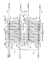
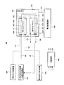
- FIG. 1 is a schematic diagram showing a schematic configuration of a fuel cell according to Embodiment 1 of the present invention.
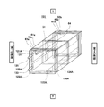
- FIG. 2 is a perspective view schematically showing a schematic configuration of the first cell stack of the fuel cell shown in FIG.
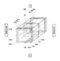
- FIG. 3 is a perspective view schematically showing a schematic configuration of a second cell stack of the fuel cell shown in FIG. 4 is a cross-sectional view schematically showing a schematic configuration of a first cell of the fuel cell shown in FIG.
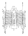
- FIG. 5 is a schematic diagram showing a schematic configuration of a fuel cell according to Embodiment 2 of the present invention.
- FIG. 6 is a perspective view schematically showing a schematic configuration of the second cell stack shown in FIG. FIG.
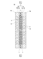
- FIG. 7 is a front view schematically showing a schematic configuration of the connection plate of the fuel cell shown in FIG. 8 is a cross-sectional view taken along line AA shown in FIG.
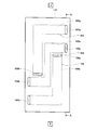
- FIG. 9 is a front view schematically showing a schematic configuration of the plate member of the connection plate shown in FIG.
- FIG. 10 is a front view schematically showing a schematic configuration of the plate member of the connection plate shown in FIG.
- FIG. 13 is a front view schematically showing a schematic configuration of the plate member of the connection plate shown in FIG. FIG.
- FIG. 14 is a front view schematically showing a schematic configuration of the plate member of the connection plate shown in FIG.
- FIG. 15 is a front view schematically showing a schematic configuration of the plate member of the connection plate shown in FIG.
- FIG. 16 is a schematic diagram showing a schematic configuration of a fuel cell according to Embodiment 3 of the present invention.
- FIG. 17 is a front view schematically showing a schematic configuration of the connection plate of the fuel cell shown in FIG.
- FIG. 18 is a schematic diagram showing a schematic configuration of a fuel cell according to Embodiment 4 of the present invention.
- FIG. 19 is a schematic diagram showing a schematic configuration of a fuel cell according to Embodiment 5 of the present invention.
- FIG. 20 is a perspective view schematically showing a schematic configuration of the first cell block of the fuel cell shown in FIG.
- FIG. 21 is a perspective view schematically showing a schematic configuration of a second cell block of the fuel cell shown in FIG.
- FIG. 22 is a schematic diagram showing a schematic configuration of the fuel cell according to Embodiment 6 of the present invention.
- FIG. 23 is a schematic diagram showing a schematic configuration of a fuel cell system according to Embodiment 7 of the present invention.
- FIG. 1 is a schematic diagram showing a schematic configuration of a fuel cell according to Embodiment 1 of the present invention.
- the vertical direction of the fuel cell is shown as the vertical direction in the drawing, and a part thereof is omitted.
- the fuel cell 100 includes a first cell block 101 in which one or more first cells 51 are stacked, and one or more second cells 52 stacked.
- the second cell block 102 is provided, and two cell blocks of the first cell block 101 and the second cell block 102 are juxtaposed.
- 63a and 63b are arranged.
- the electrical wiring 106 is arrange
- Terminals 64 and 64 are provided on the second current collector 61b of the first cell block 101 and the first current collector 61a of the second cell block 102, respectively. One end (not shown) is connected, and the other end is connected to an inverter (not shown in FIG. 1). Thereby, the direct current generated in the fuel cell 100 is output to the inverter, converted into an alternating current by the inverter, and power is supplied to the power load.
- the fuel cell 100 also includes a cooling medium connection channel 103, a fuel gas connection channel 104, and an oxidant gas connection channel 105.
- the agent gas connection flow path 105 includes a cell block internal coolant flow path 151A, a cell block internal fuel gas flow path 152A, a cell block internal oxidant gas flow path 153A, and a second cell block, respectively.
- 102, the cell block internal cooling medium flow path 151B, the cell block internal fuel gas flow path 152B, and the cell block internal oxidant gas flow path 153B are connected in series.
- the cell block internal cooling medium flow path 151A of the first cell block 101 penetrates the first cell block 101 and diverts each first cell 51 of the first cell block 101 so that the cooling medium. Including a cooling medium supply manifold 125A, the cooling medium flow paths 10 of all the first cells 51, and a cooling medium discharge manifold 126A. Further, the cell block internal fuel gas flow path 152A of the first cell block 101 penetrates the first cell block 101 and flows fuel gas so as to divert each first cell 51 of the first cell block 101.
- the flow path includes a fuel gas supply manifold 121A, the fuel gas flow paths 8 of all the first cells 51, and a fuel gas discharge manifold 122A.
- the oxidant gas flow path 153A inside the cell block 101 of the first cell block 101 passes through the first cell block 101 and divides each first cell 51 of the first cell block 101 to oxidize.
- This is a flow path for flowing gas, and includes an oxidant gas supply manifold 123A, an oxidant gas flow path 9 of all the first cells 51, and an oxidant gas discharge manifold 124A.
- the cell block internal cooling medium flow path 151B of the second cell block 102 penetrates the second cell block 102 and diverts each second cell 52 of the second cell block 102 to supply the cooling medium.
- the cell block internal fuel gas flow path 152B of the second cell block 102 penetrates the second cell block 102 and allows fuel gas to flow through the respective second cells 52 of the second cell block 102.
- the flow path includes a fuel gas supply manifold 121B, fuel gas flow paths 8 of all the second cells 52, and a fuel gas discharge manifold 122B.
- the oxidant gas flow path 153B inside the cell block 102 of the second cell block 102 penetrates the second cell block 102 and divides each second cell 52 of the second cell block 102 to oxidize.
- This is a flow path for flowing gas, and includes the oxidant gas supply manifold 123B, the oxidant gas flow paths 9 of all the second cells 52, and the oxidant gas discharge manifold 124B.
- the cell block internal fuel gas flow path 152A of the first cell block 101 and the cell block internal fuel gas flow path 152B of the second cell block 102 are connected in series.
- the present invention is not limited to this, and the cell block internal fuel gas flow path 152A of the first cell block 101 and the cell block internal fuel gas flow path 152B of the second cell block 102 may be connected in parallel.
- the cell block internal oxidant gas flow path 153A of the first cell block 101 and the cell block internal oxidant gas flow path 153B of the second cell block 102 are connected in series, but the present invention is not limited thereto.
- the cell block internal oxidant gas flow path 153A of the first cell block 101 and the cell block internal oxidant gas flow path 153B of the second cell block 102 may be connected in parallel.
- that two flow paths are connected in series means that the downstream end (exit) of one flow path and the upstream end (inlet) of the other flow path are connected.
- the phrase “two flow paths are connected in parallel” means that the upstream end (inlet) of one flow path is connected to the upstream end (inlet) of the other flow path.
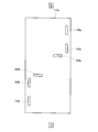
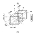
- FIG. 2 is a perspective view schematically showing a schematic configuration of the first cell block 101 of the fuel cell 100 shown in FIG.
- the vertical direction in the first cell block 101 is represented as the vertical direction in the figure.
- the first cell block 101 is formed by laminating first cells 51 having a plate-like overall shape in the thickness direction. And the second current collector plates 61 a and 61 b, the first and second insulating plates 62 a and 62 b, the first and second end plates 63 a and 63 b, and the first cell block 101 are fastened in the stacking direction of the first cells 51. And a fastener (not shown). Specifically, the first and second current collecting plates 61a and 61b are disposed so as to be in contact with both ends of the first cell block 101, respectively, and the first end plate 63a and the second end plate 63b are first The cell block 101 is disposed at the outermost position.
- the first and second insulating plates 62a and 62b are disposed so as to be positioned between the first and second current collecting plates 61a and 61b and the first and second end plates 63a and 63b, respectively. ing.
- the plate-like first cell 51 extends parallel to the vertical plane, and the stacking direction of the first cells 51 is a horizontal direction.
- the upper part of one side of the first cell block 101 (the left side of the drawing: hereinafter referred to as the first side) is penetrated in the stacking direction of the first cells 51 of the first cell block 101.
- a cooling medium supply manifold 125A is provided.
- One end of the cooling medium supply manifold 125A communicates with a through hole 145 formed in the first current collecting plate 61a, the first insulating plate 62a, and the first end plate 63a, and a cooling medium supply path is connected to the through hole 145. 135 (precisely, the piping constituting the cooling medium supply path 135) is connected.
- the other end of the cooling medium supply manifold 125A is closed by the second current collector plate 61b.
- an oxidant gas supply manifold 123A is provided below the cooling medium supply manifold 125A so as to penetrate in the stacking direction of the first cells 51 of the first cell block 101.
- One end of the oxidant gas supply manifold 123A communicates with a through hole 143 formed in the first current collecting plate 61a, the first insulating plate 62a, and the first end plate 63a, and the oxidant gas is supplied to the through hole 143.
- a supply path 133 (precisely, piping constituting the oxidant gas supply path 133) is connected.
- the other end of the oxidant gas supply manifold 123A is closed by the second current collector plate 61b.
- a fuel gas supply manifold 121A is provided inside the cooling medium supply manifold 125A so as to penetrate in the stacking direction of the first cells 51 of the first cell block 101.
- One end of the fuel gas supply manifold 121A communicates with a through hole 141 formed in the first current collecting plate 61a, the first insulating plate 62a, and the first end plate 63a, and a fuel gas supply path is connected to the through hole 141.
- 131 (precisely, piping constituting the fuel gas supply path 131) is connected.
- the other end of the fuel gas supply manifold 121A is closed by the second current collecting plate 61b.
- a lower portion of the other side portion (right side portion in the drawing: hereinafter referred to as a second side portion) in the first cell block 101 penetrates in the stacking direction of the first cells 51 of the first cell block 101.
- a cooling medium discharge manifold 126A is provided.
- One end (exit) of the cooling medium discharge manifold 126A communicates with a through hole 146 formed in the second current collecting plate 61b, the second insulating plate 62b, and the second end plate 63b.
- a medium connection channel 103 (more precisely, a pipe constituting the cooling medium connection channel 103) is connected.
- the other end of the cooling medium discharge manifold 126A is closed by the first current collecting plate 61a.
- an oxidant gas discharge manifold 124A is provided above the cooling medium discharge manifold 126A so as to penetrate in the stacking direction of the first cells 51 of the first cell block 101.
- One end (exit) of the oxidant gas discharge manifold 124A communicates with a through hole 146 formed in the second current collecting plate 61b, the second insulating plate 62b, and the second end plate 63b.
- An oxidant gas connection channel 105 (more precisely, a pipe constituting the oxidant gas connection channel 105) is connected.
- the other end of the oxidant gas discharge manifold 124A is closed by the first current collector plate 61a.
- a fuel gas discharge manifold 122A is provided inside the lower portion of the cooling medium discharge manifold 126A so as to penetrate in the stacking direction of the first cells 51 of the first cell block 101.
- One end (exit) of the fuel gas discharge manifold 122A communicates with a through hole 142 formed in the second current collecting plate 61b, the second insulating plate 62b, and the second end plate 63b.
- a gas connection channel 104 (more precisely, a pipe constituting the fuel gas connection channel 104) is connected.
- the other end of the fuel gas discharge manifold 122A is closed by the first current collecting plate 61a.
- the configuration of the second cell block 102 will be described in detail with reference to FIGS. 1 and 3. Since the second cell block 102 has the same basic configuration as the first cell block 101, only the differences will be described.
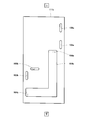
- FIG. 3 is a perspective view schematically showing a schematic configuration of the second cell block 102 of the fuel cell 100 shown in FIG.
- the vertical direction in the second cell block 102 is shown as the vertical direction in the figure.
- one end of the fuel gas supply manifold 121B of the second cell block 102 is closed to the first current collector 61a, and the other end (inlet) is the second current collector 61b.
- the through hole 141 formed in the second insulating plate 62b and the second end plate 63b communicates with the fuel gas connection channel 104 (more precisely, the fuel gas connection channel 104 is configured. Connected).
- one end of the fuel gas discharge manifold 122B of the second cell block 102 communicates with a through hole 142 formed in the first current collecting plate 61a, the first insulating plate 62a, and the first end plate 63a.
- a fuel gas discharge path 132 (more precisely, piping constituting the fuel gas discharge path 132).
- the other end of the fuel gas discharge manifold 122B of the second cell block 102 is closed by the second current collecting plate 61b.
- One end of the oxidant gas supply manifold 123B of the second cell block 102 is closed by the first current collector 61a, and the other end (inlet) is the second current collector 61b, the second insulating plate 62b, And the through hole 143 formed in the second end plate 63b is connected to the oxidant gas connection channel 105 (more precisely, the pipe constituting the oxidant gas connection channel 105).
- One end of the oxidant gas discharge manifold 124B of the second cell block 102 communicates with a through hole 144 formed in the first current collecting plate 61a, the first insulating plate 62a, and the first end plate 63a.
- the hole 144 is connected to an oxidant gas discharge path 134 (more precisely, a pipe constituting the oxidant gas discharge path 134).
- an oxidant gas discharge path 134 more precisely, a pipe constituting the oxidant gas discharge path 134.
- the other end of the oxidizing gas discharge manifold 124B of the second cell block 102 is closed by the second current collector plate 61b.
- one end of the cooling medium supply manifold 125B of the second cell block 102 is closed by the first current collector 61a, and the other end (inlet) is the second current collector 61b, the second insulating plate 62b, and The through hole 145 formed in the second end plate 63b communicates with the through hole 145, and the through hole 145 is connected to the cooling medium connection channel 103 (more precisely, the pipe constituting the cooling medium connection channel 103). . Further, one end of the cooling medium discharge manifold 126B of the second cell block 102 communicates with a through hole 146 formed in the first current collecting plate 61a, the first insulating plate 62a, and the first end plate 63a.
- a cooling medium discharge path 136 (more precisely, piping constituting the cooling medium discharge path 136).
- the other end of the cooling medium discharge manifold 126B of the second cell block 102 is closed by the second current collector plate 61b.
- the fuel gas and the oxidant gas that have flowed through the first cell block 101 flow through the fuel gas connection channel 104 and the oxidant gas connection channel 105, respectively, and are supplied to the second cell block 102. .
- the cooling medium supplied to the first cell block 101 flows through the cooling medium connection channel 103 and is supplied to the second cell block 102. That is, the first cell block 101 is positioned upstream of the cooling medium connection flow path 103 to form a cooling medium upstream cell block, and the second cell block 102 is positioned downstream of the cooling medium connection flow path 103.
- the cooling medium downstream cell block is configured.
- the cooling medium flowing through the first cell block 101 is heated by collecting heat generated by the reaction between the fuel gas and the oxidant gas in each first cell 51 of the first cell block 101.
- the temperature of the 2-cell block 102 is higher than that of the first cell block 101. For this reason, the cooling medium discharged
- the second cell block 102 has a higher internal temperature than the first cell block 101, so the second cell block 102 has a relative humidity higher than that of the first cell block 101. Lower.
- the configuration of the first cell 51 constituting the first cell block 101 and the second cell 52 constituting the second cell block 102 will be described in detail with reference to FIG. Since the basic configuration of the first cell 51 and the second cell 52 is the same, only the difference between the first cell 51 and the first cell 51 will be described.
- FIG. 4 is a cross-sectional view schematically showing a schematic configuration of the first cell 51 of the fuel cell 100 shown in FIG.
- the first cell 51 includes a MEA (Membrane-Electrode-Assembly: membrane-electrode assembly (electrolyte layer-electrode assembly)) 5, a gasket 7, an anode separator 6a, and a cathode separator 6b. And.
- MEA Membrane-Electrode-Assembly: membrane-electrode assembly (electrolyte layer-electrode assembly)
- gasket 7 an anode separator 6a
- cathode separator 6b cathode separator
- the MEA 5 includes a polymer electrolyte membrane (electrolyte layer) 1 that selectively transports hydrogen ions, an anode electrode 4a, and a cathode electrode 4b.
- the polymer electrolyte membrane 1 has a substantially quadrangular (here, rectangular) shape, and an anode electrode 4a and a cathode are positioned on both sides of the polymer electrolyte membrane 1 so as to be located inward from the peripheral edge thereof.
- Each electrode 4b is provided.
- manifold holes such as an oxidant gas discharge manifold hole are provided in the periphery of the polymer electrolyte membrane 1 so as to penetrate in the thickness direction.
- the anode electrode 4a is provided on one main surface of the polymer electrolyte membrane 1, and comprises a catalyst-carrying carbon (catalyst carrier) made of carbon powder (conductive carbon particles) carrying a platinum-based metal catalyst (electrode catalyst).
- An anode catalyst layer 2a containing a polymer electrolyte attached to the catalyst-supporting carbon, and an anode gas diffusion layer 3a provided on the anode catalyst layer 2a and having both gas permeability and conductivity are provided.
- the cathode electrode 4b is provided on the other main surface of the polymer electrolyte membrane 1, and is a catalyst-supported carbon (catalyst support) made of carbon powder (conductive carbon particles) supporting a platinum-based metal catalyst (electrode catalyst). Body) and a cathode catalyst layer 2b containing a polymer electrolyte attached to the catalyst-supporting carbon, and a cathode gas diffusion layer 3b provided on the cathode catalyst layer 2b and having both gas permeability and conductivity.
- the polymer electrolyte membrane 1 has proton conductivity.
- the polymer electrolyte membrane 1 preferably has a sulfonic acid group, a carboxylic acid group, a phosphonic acid group, and a sulfonimide group as cation exchange groups. Further, from the viewpoint of proton conductivity, the polymer electrolyte membrane 1 preferably has a sulfonic acid group.
- the resin having a sulfonic acid group constituting the polymer electrolyte membrane 1 is preferably a dry resin having an ion exchange capacity of 0.5 to 2.0 meq / g.
- the ion exchange capacity of the dry resin constituting the polymer electrolyte membrane 1 is 0.5 meq / g or more, an increase in the resistance value of the polymer electrolyte membrane 1 during power generation can be sufficiently reduced.
- the ion exchange capacity of the dry resin is 2.0 meq / g or less, the moisture content of the polymer electrolyte membrane does not increase and the swelling becomes difficult to swell, and the pores in the anode catalyst layer 2a and the cathode catalyst layer 2b are blocked. It is preferable because there is no fear of doing so.
- a perfluorovinyl compound represented by CF 2 ⁇ CF— (OCF 2 CFX) m —O p — (CF 2 ) n —SO 3 H (m represents an integer of 0 to 3, n Represents an integer of 1 to 12, p represents 0 or 1, and X represents a fluorine atom or a trifluoromethyl group.)
- a copolymer comprising a polymer unit based on tetrafluoroethylene It is preferable that
- fluorovinyl compound examples include compounds represented by the following formulas (1) to (3).
- q is an integer of 1 to 8
- r is an integer of 1 to 8
- t is an integer of 1 to 3.
- the anode catalyst layer 2a and the cathode catalyst layer 2b are not particularly limited as long as the effects of the present invention can be obtained, and may have the same configuration as the catalyst layer of the gas diffusion electrode in a known fuel cell,
- the catalyst-supporting carbon made of carbon powder (conductive carbon particles) supporting an electrode catalyst and the polymer electrolyte attached to the catalyst-supporting carbon may further include a water-repellent material such as polytetrafluoroethylene. Good.
- the configurations of the anode catalyst layer 2a and the cathode catalyst layer 2b may be the same or different.
- the carbon powder used as the catalyst carrier preferably has a specific surface area in the range of 50 to 2000 m 2 / g.
- the specific surface area of the carbon powder is 50 m 2 / g or more, it is easy to carry the electrode catalyst in a highly dispersed state, and at the same time, the space capable of holding moisture increases even when the relative humidity is low, and the anode catalyst This is preferable because drying of the layer 2a and the cathode catalyst layer 2b can be prevented.
- the specific surface area of the carbon powder is 2000 m 2 / g or less, it becomes easy to ensure the oxidation resistance of the carbon powder, and corrosion of the carbon powder can be prevented even when exposed to a high potential. Therefore, it is preferable.
- metal particles can be used as the electrode catalyst.
- the metal particles are not particularly limited, and various metals can be used. From the viewpoint of electrode reaction activity, platinum, gold, silver, ruthenium, rhodium, palladium, osmium, iridium, chromium, iron, titanium, It is preferably at least one metal selected from the metal group consisting of manganese, cobalt, nickel, molybdenum, tungsten, aluminum, silicon, zinc and tin. Among these, platinum or an alloy of platinum and at least one metal selected from the above metal group is preferable, and an alloy of platinum and ruthenium is particularly preferable because the activity of the catalyst is stabilized in the anode catalyst layer 2a.
- the loading ratio of the electrode catalyst to the catalyst-supporting carbon used for the anode catalyst layer 2a and the cathode catalyst layer 2b is preferably in the range of 10 wt% to 90 wt%.
- the catalyst loading is 10 wt% or more, the thickness of the anode catalyst layer 2a and / or the cathode catalyst layer 2b with respect to a predetermined amount of the electrode catalyst can be reduced, and the anode catalyst layer 2a and / or the cathode catalyst layer 2b Since ion conductivity, gas diffusibility, and water discharge
- the catalyst loading ratio is 90 wt% or less because it becomes easy to carry the electrode catalyst in a highly dispersed state and high power generation efficiency can be obtained.
- the first cell block 101 since the first cell block 101 has a high relative humidity, it is effective to carry the electrode catalyst in a highly dispersed state in order to obtain high power generation efficiency, while the second cell block 102 has a low relative humidity. Therefore, in order to obtain high power generation efficiency, it is effective to increase the ionic conductivity in the anode catalyst layer 2a and the cathode catalyst layer 2b. For this reason, as a whole fuel cell 100, from the viewpoint of reducing cost and increasing power generation efficiency, the loading ratio of the electrode catalyst to the catalyst-supporting carbon used for at least one of the anode catalyst layer 2 a and the cathode catalyst layer 2 b of the second cell 52. Is configured to be larger than the loading ratio of the electrode catalyst to the catalyst-supporting carbon used in the anode catalyst layer 2a and the cathode catalyst layer 2b of the first cell 51.
- the amount of the electrode catalyst supported on the catalyst-supported carbon used for the anode catalyst layer 2a and the cathode catalyst layer 2b is preferably in the range of 0.01 mg / cm 2 to 10 mg / cm 2 . It is preferable that the amount of the electrode catalyst supported is 0.01 mg / cm 2 or more because the reaction overvoltage of the electrochemical reaction can be reduced. Further, it is preferable that the amount of the electrode catalyst supported is 10 mg / cm 2 or less because the cost for the electrode catalyst can be suppressed.
- the electrode catalyst has a low relative humidity.
- the effect of reducing the reaction overvoltage significantly appears when the relative humidity of the anode catalyst layer 2a and / or the cathode catalyst layer 2b is low.
- the amount of electrode catalyst supported on the catalyst-supported carbon used for at least one of the anode catalyst layer 2a and the cathode catalyst layer 2b of the second cell 52 from the viewpoint of reducing the cost and increasing the power generation efficiency of the fuel cell 100 as a whole. Is configured to be larger than the amount of the electrode catalyst supported on the catalyst-supported carbon used for the anode catalyst layer 2a and the cathode catalyst layer 2b of the first cell 51.
- the same kind of material as that of the polymer electrolyte membrane 1 described above may be used, or different kinds of materials may be used. May be.
- the ion exchange capacity is preferably a dry resin of 0.5 to 2.0 meq / g.
- the ion exchange capacity of the dry resin (polymer electrolyte) constituting the polymer electrolyte is 0.5 meq / g or more, the ion conductivity in the catalyst layer can be increased, and at the same time the relative humidity is low. This is preferable because the water content is increased and drying of the catalyst layer can be prevented.
- the ion exchange capacity of the dry resin is 2.0 meq / g or less, swelling of the polymer electrolyte due to water content can be suppressed, and pores in the catalyst layer are blocked and gas diffusion is not hindered. Therefore, it is preferable.
- the first cell block 101 has a high relative humidity, and the pores in the catalyst layer are likely to be blocked by swelling of the polymer electrolyte or generated water, while the second cell block 102 has a low relative humidity and the catalyst layer. Becomes dry, and the ionic conductivity in the catalyst layer tends to decrease. For this reason, the ion exchange capacity of the polymer electrolyte used for at least one of the anode catalyst layer 2a and the cathode catalyst layer 2b of the second cell 52 from the viewpoint of reducing the cost and increasing the power generation efficiency as the fuel cell 100 as a whole.
- the ion exchange capacity of the polymer electrolyte used for the anode catalyst layer 2a and the cathode catalyst layer 2b of the first cell 51 is configured to be larger.
- the density of ion exchange groups per unit deposition of at least one catalyst layer of the anode catalyst layer 2a and the cathode catalyst layer 2b of the second cell 52 is at least that of the anode catalyst layer 2a and the cathode catalyst layer 2b of the first cell 51.
- One catalyst layer is configured to be larger than the density of ion exchange groups per unit deposition.
- the amount of the polymer electrolyte used for the anode catalyst layer 2a and the cathode catalyst layer 2b is the ratio of the mass WP of the polymer electrolyte to the mass Wcat-C of the catalyst-supported carbon contained in the anode catalyst layer 2a or the cathode catalyst layer 2b ( It is preferable to adjust so that WP / WCat-C) is 0.3 to 3.0. It is preferable that WP / WCat-C is 0.3 or more because an ion conduction path is effectively formed in the catalyst layer and ion conductivity in the anode catalyst layer 2a and the cathode catalyst layer 2b is increased.
- the gas diffusibility in the anode catalyst layer 2a and the cathode catalyst layer 2b is likely to be lowered due to swelling of the polymer electrolyte or generated water, while the second cell Since the relative humidity of the block 102 is low, the anode catalyst layer 2a and the cathode catalyst layer 2b are dried, and the ionic conductivity in the anode catalyst layer 2a and the cathode catalyst layer 2b is likely to be lowered.
- the mass of catalyst-supported carbon WCat-C used for at least one of the anode catalyst layer 2a and the cathode catalyst layer 2b of the second cell 52 is reduced.
- the ratio of the mass WP of the polymer electrolyte (WP / WCat-C) is the ratio of the mass WP of the polymer electrolyte to the mass W Cat-C of the catalyst-supporting carbon used in the anode catalyst layer 2a and the cathode catalyst layer 2b of the first cell 51. It is configured to be larger than (WP / WCat-C).
- the density of ion exchange groups per unit deposition of at least one catalyst layer of the anode catalyst layer 2a and the cathode catalyst layer 2b of the second cell 52 is at least that of the anode catalyst layer 2a and the cathode catalyst layer 2b of the first cell 51.
- One catalyst layer is configured to be larger than the density of ion exchange groups per unit deposition.
- anode gas diffusion layer 3a and the cathode gas diffusion layer 3b for example, a porous material produced using a high surface area carbon fine powder, a pore-forming material, carbon paper, carbon cloth, or the like to give gas permeability.
- a conductive base material having a texture structure may be used.
- a water repellent polymer typified by a fluororesin may be dispersed in the anode gas diffusion layer 3a or the cathode gas diffusion layer 3b.
- the anode gas diffusion layer 3a or the cathode gas diffusion layer 3b may be made of an electron conductive material such as carbon fiber, metal fiber, or carbon fine powder.
- a water repellent carbon layer composed of a water repellent polymer and carbon powder is provided between the anode gas diffusion layer 3a and the anode catalyst layer 2a and between the cathode gas diffusion layer 3b and the cathode catalyst layer 2b. May be provided. Thereby, water management in MEA 5 (retention of water necessary for maintaining good characteristics of MEA 5 and rapid drainage of unnecessary water) can be performed more easily and more reliably.
- a manifold hole such as an oxidant gas discharge manifold hole made of a through hole in the thickness direction is provided at the peripheral edge of the gasket 7.
- a conductive anode separator 6a and a cathode separator 6b are disposed so as to sandwich the MEA 5 and the gasket 7.
- MEA 5 is mechanically fixed, and when a plurality of first cells 51 are stacked in the thickness direction, MEA 5 is electrically connected.
- these separators 6a and 6b can use the metal excellent in heat conductivity and electroconductivity, graphite, or what mixed graphite and resin, for example, carbon powder and a binder (solvent).
- a mixture prepared by injection molding or a plate of titanium or stainless steel plated with gold can be used.
- a groove-shaped fuel gas flow path 8 for allowing the fuel gas to flow is provided, and the other main surface is provided.
- a groove-like cooling medium flow path 10 through which the cooling medium flows is provided on the surface (hereinafter referred to as an outer surface).
- a groove-like oxidant gas flow path 9 through which an oxidant gas flows is provided on one main surface (hereinafter referred to as an inner surface) that contacts the cathode electrode 4b of the cathode separator 6b.
- the other main surface (hereinafter referred to as an outer surface) is provided with a groove-like cooling medium flow path 10 through which the cooling medium flows.
- the fuel gas channel 8 and the oxidant gas channel 9 are provided so as to be a so-called counter flow.
- the counter flow has a part in which the oxidant gas and the fuel gas flow in parallel to each other when viewed from the thickness direction of the first cell 51 (or the second cell 52). It means that the directions of the overall flow from the upstream side to the downstream side of the oxidant gas and the fuel gas are opposite to each other (as a whole).
- fuel gas and oxidant gas are supplied to the anode electrode 4a and the cathode electrode 4b, respectively, and these gases react to generate electricity and heat. Further, the generated heat is recovered by passing a cooling medium such as cooling water through the cooling medium flow path 10.
- the cell block internal coolant flow channel 151A of the first cell block 101 and the cell block internal coolant flow channel 151B of the second cell block 102 are provided.
- the cooling medium connection channel 103 is connected in series.
- the fuel cell 100 is supplied with fuel gas, oxidant gas, and cooling medium.
- a fuel gas and an oxidant gas having a dew point temperature lower than the temperature of the cooling medium supplied to the fuel cell 100 are supplied to the fuel cell 100.
- the dew point temperatures of the fuel gas and the oxidant gas supplied to the fuel cell 100 may be higher than the temperature of the cooling medium supplied to the fuel cell 100.
- the cooling medium supplied to the first cell block 101 is divided and supplied to the cooling medium flow path 10 of each first cell 51 while flowing through the cooling medium supply manifold 125A.
- the cooling medium supplied to the cooling medium flow path 10 collects heat generated by the reaction between the fuel gas and the oxidant gas in the MEA 5 of the first cell 51 while flowing through the cooling medium flow path 10. Heated.
- the heated cooling medium joins the cooling medium discharge manifold 126 ⁇ / b> A of the first cell block 101, flows through the cooling medium discharge manifold 126 ⁇ / b> A, and is supplied to the cooling medium connection channel 103.
- the cooling medium supplied to the cooling medium connection flow path 103 flows through the cooling medium connection flow path 103 and is supplied to the second cell block 102.
- the internal temperature of the second cell block 102 can be made higher than that of the first cell block 101.
- the cooling medium heated through the first cell block 101 flows through the second cell block 102, the reaction between the fuel gas and the oxidant gas occurs in the MEA 5 of the second cell 52. Since the generated heat is recovered and further heated, the cooling medium discharged from the cooling medium discharge manifold 126B of the second cell block 102 can be heated to a higher temperature.
- the fuel gas connection channel 104 connects the cell block internal fuel gas channel 152A of the first cell block 101 and the cell block internal fuel gas channel 152B of the second cell block 102.
- the oxidant gas connection flow path 105 connects the cell block internal oxidant gas flow path 153A of the first cell block 101 and the cell block internal oxidant gas flow path 153B of the second cell block 102 in series. ing.
- the fuel gas and the oxidant gas supplied to the first cell block 101 flow through the fuel gas supply manifold 121A and the oxidant gas supply manifold 123A, respectively.
- the flow is divided and supplied to the passage 8 and the oxidant gas passage 9, respectively.
- the fuel gas and the oxidant gas supplied to the fuel gas channel 8 and the oxidant gas channel 9 react in the MEA 5 of the first cell 51 to generate water.
- the generated water humidifies the fuel gas and the oxidant gas, and the humidified fuel gas and oxidant gas flow through the fuel gas discharge manifold 122A and the oxidant gas discharge manifold 124A, respectively.
- the gas connection channel 104 and the oxidant gas connection channel 105 are supplied.
- the fuel gas and the oxidant gas supplied to the fuel gas connection channel 104 and the oxidant gas connection channel 105 flow through the fuel gas connection channel 104 and the oxidant gas connection channel 105, respectively.
- the second cell block 102 has a higher internal temperature than the first cell block 101.
- the first cell block 101 is 65 ° C. and the second cell block 102 is 80 ° C.
- the relative humidity of the second cell block 102 is lower than that of the first cell block 101. That is, the relative humidity of the fuel gas flowing through the cell block internal fuel gas flow path 152B of the second cell block 102 is greater than that of the fuel gas flowing through the cell block internal fuel gas flow path 152A of the first cell block 101.
- the relative humidity of the oxidant gas that is lower than the relative humidity and flows through the cell block internal oxidant gas flow path 153B of the second cell block 102 is greater than the cell block internal oxidant gas flow of the first cell block 101.
- the power generation operation can be performed under conditions lower than the relative humidity of the oxidant gas flowing through the path 153A.
- the supported amount, the ion exchange capacity of the polymer electrolyte, and the ratio of the mass WP of the polymer electrolyte to the mass WCat-C of the catalyst-supported carbon (WP / WCat-C) are determined by the anode catalyst layer 2a and the cathode catalyst of the first cell 51.
- the pores in the catalyst layer due to the swelling of the polymer electrolyte or the generated water are generated even at a low temperature and a high relative humidity. Clogging, swelling of the polymer electrolyte, and gas diffusibility in the anode catalyst layer 2a and the cathode catalyst layer 2b due to the generated water can be suppressed from being lowered, thereby increasing power generation efficiency.
- the second cell block 102 suppresses drying of the anode catalyst layer 2a and the cathode catalyst layer 2b even at a high temperature and a low relative humidity, and ion conduction in the anode catalyst layer 2a and the cathode catalyst layer 2b. Therefore, the power generation efficiency can be increased.
- the temperature of the cooling medium discharged from the second cell block 102 of the fuel cell 100 is increased, and it is high without increasing the cost and size of the humidifier. Power generation efficiency can be realized.
- the supported amount, the ion exchange capacity of the polymer electrolyte, and the ratio of the mass WP of the polymer electrolyte to the mass WCat-C of the catalyst-supported carbon (WP / WCat-C) are determined by the anode catalyst layer 2a and the cathode catalyst of the first cell 51.
- the ratio of the electrode catalyst supported on the catalyst-supported carbon used in the layer 2b, the amount of electrode catalyst supported on the catalyst-supported carbon, the ion exchange capacity of the polymer electrolyte, and the ratio of the mass WP of the polymer electrolyte to the mass WCat-C of the catalyst-supported carbon Although it is configured to be larger than (WP / WCat-C), the present invention is not limited to this.
- electrode catalyst with respect to 52 catalyst-supported carbon amount of electrode catalyst supported with respect to catalyst-supported carbon, ion exchange capacity of polymer electrolyte, and ratio of mass WP of polymer electrolyte to mass Wcat-C of catalyst-supported carbon (WP / WCat-C) includes at least one electrode catalyst supported on the catalyst-supported carbon used in the anode catalyst layer 2a and the cathode catalyst layer 2b of the first cell 51, the amount of the electrode catalyst supported on the catalyst-supported carbon, and the polymer electrolyte.
- the above-described effects are achieved if the ion exchange capacity and the ratio of the mass WP of the polymer electrolyte to the mass WCat-C of the catalyst-supporting carbon (WP / WCat-C) are set larger.
- FIG. 5 is a schematic diagram showing a schematic configuration of a fuel cell according to Embodiment 2 of the present invention.
- the vertical direction of the fuel cell is shown as the vertical direction in the drawing, and a part of it is omitted.
- the fuel cell 100 according to the second embodiment of the present invention has the same basic configuration as the fuel cell 100 according to the first embodiment, but the fuel gas supply manifold of the second cell block 102. 121B and other manifolds are arranged differently, and a connection plate 111 is disposed so as to connect the end portions of the first cell block 101 and the second cell block 102, and a cooling medium connection flow is provided in the connection plate 111.
- the point that the path 103, the fuel gas connection channel 104, and the oxidant gas connection channel 105 are provided, and the point that the heat insulating member 112 is provided between the first cell block 101 and the second cell block 102. Is different. Hereinafter, these differences will be described.
- each manifold such as the fuel gas supply manifold 121B of the second cell block 102 will be described with reference to FIGS.
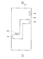
- FIG. 6 is a perspective view schematically showing a schematic configuration of the second cell block 102 shown in FIG.
- the vertical direction in the second cell block 102 is represented as the vertical direction in the figure.
- a cooling medium supply manifold 125 ⁇ / b> B is provided above the first side portion of the second cell block 102 so as to penetrate in the stacking direction of the second cells 52 of the second cell block 102.
- a fuel gas supply manifold 121 ⁇ / b> B is provided at a lower portion thereof so as to penetrate in the stacking direction of the second cells 52 of the second cell block 102.
- an oxidant gas supply manifold 123B is provided inside the upper part of the cooling medium supply manifold 125B so as to penetrate in the stacking direction of the second cells 52 of the second cell block 102.
- a cooling medium discharge manifold 126B is provided at the lower part of the second side portion of the second cell block 102 so as to penetrate in the stacking direction of the second cells 52 of the second cell block 102.
- the fuel gas discharge manifold 122B is provided so as to penetrate in the stacking direction of the second cells 52 of the second cell block 102.
- an oxidant gas discharge manifold 124B is provided inside the lower portion of the cooling medium discharge manifold 126B so as to penetrate in the stacking direction of the second cells 52 of the second cell block 102.
- the heat insulation member 112 may be any member as long as heat exchange between the first cell block 101 and the second cell block 102 can be suppressed.
- the heat insulating member 112 may be ceramic or resin-based heat insulating material including bubbles. You may be comprised with the material, the vacuum heat insulating material, etc. Further, for example, it may be configured by a member in which a ceramic, a resin-based heat insulating material containing bubbles, a vacuum heat insulating material, or the like is sandwiched between resin plates.
- the cooling medium discharged from the second cell block 102 can be kept at a high temperature.
- the distance between the 1st cell block 101 and the 2nd cell block 102 will be large. In such a case, the heat insulating member 112 may not be provided.
- connection plate 111 is disposed so as to come into contact with the main surface of the second end plate 63b of the first cell block 101 and the main surface of the second end plate 63b of the second cell block 102.
- the configuration of the connection plate 111 will be described with reference to FIGS. 5, 7, and 8.
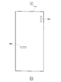
- FIG. 7 is a front view schematically showing a schematic configuration of the connection plate 111 of the fuel cell 100 shown in FIG. 5, and FIG. 8 is a cross-sectional view taken along line AA shown in FIG. 7 and 8, the vertical direction in the connection plate 111 is represented as the vertical direction in the drawings.
- connection plate 111 is composed of plate members 111 a to 111 g, and has a main surface (hereinafter referred to as an inner surface) that contacts the second end plate 63 b of the connection plate 111. Is formed with a recess 105a so as to communicate with the through hole 144 of the first cell block 101 (the oxidizing gas discharge manifold 124A of the first cell block 101), and the through hole 143 of the second cell block 102. A recess 105b is formed so as to communicate with (the oxidizing gas supply manifold 123B of the second cell block 102).
- a tunnel-like flow path 105c is formed inside the connection plate 111 so as to communicate the recess 105a and the recess 105b.
- the recess 105a, the flow path 105c, and the recess 105b constitute an oxidant gas connection flow path 105.
- a recess 103a is formed on the inner surface of the connection plate 111 so as to communicate with the through hole 146 of the first cell block 101 (the cooling medium discharge manifold 126A of the first cell block 101).
- a recess 103b is formed so as to communicate with the through hole 145 of the cell block 102 (the cooling medium supply manifold 125B of the second cell block 102).
- a tunnel-like flow path 103c is formed inside the connection plate 111 so as to communicate the recess 103a and the recess 103b.
- the recess 103a, the channel 103c, and the recess 103b constitute a cooling medium connection channel 103.
- a recess 104a is formed on the inner surface of the connection plate 111 so as to communicate with the through hole 142 of the first cell block 101 (the fuel gas discharge manifold 122A of the first cell block 101).
- a recess 104b is formed so as to communicate with the through hole 141 of the cell block 102 (the fuel gas supply manifold 121B of the second cell block 102).
- a tunnel-like flow path 104c is formed inside the connection plate 111 so as to communicate the recess 104a and the recess 104b.
- the fuel gas connection flow path 104 is configured by the recess 104a, the flow path 104c, and the recess 104b.
- the connection plate 111 may be any member as long as heat exchange between the first cell block 101 and the second cell block 102 can be suppressed (that is, a material having high heat insulation).
- a material having high heat insulation you may be comprised with the ceramic, the resin-type heat insulating material containing a bubble, a vacuum heat insulating material, etc.
- it may be configured by a member in which a ceramic, a resin-based heat insulating material containing bubbles, a vacuum heat insulating material, or the like is sandwiched between resin plates.
- FIGS. 9 to 15 are front views schematically showing schematic configurations of the plate members 111a to 111g of the connection plate 111 shown in FIG. 7, respectively.
- the plate members 111a to 111g are bonded by an appropriate method to produce the connection plate 111.
- the plate members 111a to 111g are bonded to produce the connection plate 111.
- the present invention is not limited to this.
- the connection plate 111 is made of resin
- the connection plate 111 is produced by a hollow molding method. May be.
- the fuel cell 100 according to the second embodiment configured as described above also has the same effects as the fuel cell 100 according to the first embodiment.
- FIG. 16 is a schematic diagram showing a schematic configuration of a fuel cell according to Embodiment 3 of the present invention.
- FIG. 17 is a front view schematically showing a schematic configuration of the connection plate of the fuel cell shown in FIG.
- the vertical direction in the fuel cell is represented as the vertical direction in the figure.
- the up-down direction in the connection plate is represented as the up-down direction in the figure, and the respective flow paths are illustrated in a shifted manner in order to make each flow path easier to see.
- the basic configuration of the fuel cell 100 according to Embodiment 3 of the present invention is the same as that of the fuel cell 100 according to Embodiment 2, but the first cell block 101 and the second cell block are the same. 102 are configured in the same manner, and are arranged so as to overlap each other across the connection plate 111 when viewed from the stacking direction of the first cells 51 (or the second cells 52). The difference is that the second end plate 63b of the block 101 and the first end plate 63a of the second cell block 102 are omitted.
- the first current collecting plate 61a and the first insulating plate 62a of the first cell block 101 and the first current collecting plate 61a and the first insulating plate 62a of the second cell block 102 are configured in the same manner.
- the second current collecting plate 61b and the second insulating plate 62b of the first cell block 101 and the second current collecting plate 61b and the second insulating plate 62b of the second cell block 102 are configured in the same manner. Different from the fuel cell 100 according to the second embodiment. Further, the second current collecting plate 61b and the second insulating plate 62b of the first cell block 101 are opposed to each other across the connection plate 111 when viewed from the stacking direction of the first cells 51 (or the second cells 52).
- the electrical wiring 106 is connected to the second current collecting plate 61b of the first cell block 101 and the first current collecting plate 61a of the second cell block 102. 2 different from the fuel cell 100 according to FIG. Furthermore, the configuration of the coolant connection channel 103, the fuel gas connection channel 104, and the oxidant gas connection channel 105 provided in the connection plate 111 is different from that of the fuel cell 100 according to the second embodiment.
- a through hole 141 is provided so as to communicate (so as to communicate with the fuel gas supply manifold 121B of the second cell block 102), and so as to communicate with the oxidant gas supply manifold 123A of the first cell block 101 (
- a through hole 143 is provided so as to communicate with the oxidizing gas supply manifold 123B of the second cell block 102).
- a through hole 145 is provided so as to communicate with the cooling medium supply manifold 125A of the first cell block 101 (so as to communicate with the cooling medium supply manifold 125B of the second cell block 102).
- the main surfaces of the second current collecting plate 61b and the second insulating plate 62b of the first cell block 101 communicate with the fuel gas discharge manifold 122A of the first cell block 101.
- a through hole 142 is provided (so as to communicate with the fuel gas discharge manifold 122B of the second cell block 102), and communicates with the oxidizing gas discharge manifold 124A of the first cell block 101 (second cell).
- a through hole 144 is provided to communicate with the oxidant gas discharge manifold 124B of the block 102).
- a through hole 146 is provided so as to communicate with the cooling medium discharge manifold 126A of the first cell block 101 (so as to communicate with the cooling medium discharge manifold 126B of the second cell block 102).
- the through hole 142 of the first cell block 101 is formed on one main surface of the connection plate 111 (the main surface that contacts the second insulating plate 62 b of the first cell block 101).
- a recess 105a is formed so as to communicate with the through hole 144 of the first cell block 101 (oxidant gas discharge manifold 124A of the first cell block 101) so as to communicate with the (fuel gas discharge manifold 122A).
- the other main surface of the connection plate 111 (the main surface in contact with the first insulating plate 62a of the second cell block 102) has a through-hole 143 (the oxidizing gas of the second cell block 102) in the second cell block 102.
- a recess 105b is formed so as to communicate with the supply manifold 123B).
- a tunnel-like flow path 105c is formed inside the connection plate 111 so as to communicate the recess 105a and the recess 105b.
- the recess 105a, the flow path 105c, and the recess 105b constitute an oxidant gas connection flow path 105.
- a recess 103a is formed on one main surface of the connection plate 111 so as to communicate with the through hole 146 of the first cell block 101 (the cooling medium discharge manifold 126A of the first cell block 101).
- a recess 103b is formed so as to communicate with the through hole 145 of the second cell block 102 (the cooling medium supply manifold 125B of the second cell block 102).
- a tunnel-like flow path 103c is formed inside the connection plate 111 so as to communicate the recess 103a and the recess 103b.
- the recess 103a, the channel 103c, and the recess 103b constitute a cooling medium connection channel 103.
- a recess 104a is formed on one main surface of the connection plate 111 so as to communicate with the through hole 142 of the first cell block 101 (the fuel gas discharge manifold 122A of the first cell block 101).
- a recess 104b is formed so as to communicate with the through hole 141 of the second cell block 102 (the fuel gas supply manifold 121B of the second cell block 102).
- a tunnel-like flow path 104c is formed inside the connection plate 111 so as to communicate the recess 104a and the recess 104b.
- the fuel gas connection flow path 104 is configured by the recess 104a, the flow path 104c, and the recess 104b.
- connection plate 111 is configured to be able to suppress heat exchange between the first cell block 101 and the second cell block 102, but is not limited thereto. It is good also as a structure which arrange
- FIG. 18 is a schematic diagram showing a schematic configuration of a fuel cell according to Embodiment 4 of the present invention.
- the fuel cell 100 according to the fourth embodiment of the present invention has the same basic configuration as the fuel cell 100 according to the first embodiment, but the cell block internal fuel of the first cell block 101.
- the gas flow path 152A and the cell block internal fuel gas flow path 152B of the second cell block 102 are connected in parallel, the cell block internal oxidant gas flow path 153A of the first cell block 101 and the second cell block 102.
- the cell block internal oxidant gas flow paths 153B are connected in parallel.
- the upstream end of the fuel gas connection channel 104 is connected in the middle of the fuel gas supply channel 131, and the downstream end of the fuel gas connection channel 104 passes through the through-hole 141 of the second cell block 102. And is connected to the upstream end of the fuel gas flow path 152B inside the cell block.
- the fuel gas supply path 131 is connected to the upstream end of the cell block internal fuel gas flow path 152 ⁇ / b> A via the through hole 141 of the first cell block 101.
- the upstream end of the oxidant gas connection flow path 105 is connected to the middle of the oxidant gas supply path 133, and the downstream end of the oxidant gas connection flow path 105 is the through hole 143 of the second cell block 102. Is connected to the upstream end of the oxidant gas flow path 153B inside the cell block.
- the oxidant gas supply path 133 is connected to the upstream end of the cell block internal oxidant gas flow path 153 ⁇ / b> A via the through hole 143 of the first cell block 101.
- part of the fuel gas flowing through the fuel gas supply path 131 is diverted to the fuel gas connection flow path 104, and the fuel gas is separated from the cell block internal fuel gas flow path 152 ⁇ / b> A of the first cell block 101. It is supplied to each of the cell block internal fuel gas flow paths 152B of the second cell block 102. Further, a part of the oxidant gas flowing through the oxidant gas supply path 133 is diverted to the oxidant gas connection flow path 105, and the oxidant gas becomes the oxidant gas inside the cell block of the first cell block 101.
- the flow path 153A and the cell block internal oxidant gas flow path 153B of the second cell block 102 are respectively supplied.
- a fuel gas discharge path 132 is connected to the downstream end of the cell block internal fuel gas flow path 152A of the first cell block 101 via a through hole 142, and the cell block internal oxidant gas flow path 153A is connected.
- An oxidant gas discharge path 134 is connected to the downstream end via a through hole 144.
- the fuel gas discharge path 132 is connected to the downstream end of the cell block internal fuel gas flow path 152B of the second cell block 102 through the through hole 142, and the cell block internal oxidant gas flow path 153B.
- An oxidant gas discharge path 134 is connected to the downstream end of the oxidant gas through a through hole 144.
- the fuel gas that has not been used in the cell block internal fuel gas flow path 152A of the first cell block 101 and the cell block internal fuel gas flow path 152B of the second cell block 102 becomes the fuel of the first cell block 101, respectively.
- the gas is discharged to the gas discharge path 132 and the fuel gas discharge path 132 of the second cell block 102.
- the oxidant gas that has not been used in the cell block internal oxidant gas flow path 153A of the first cell block 101 and the cell block internal oxidant gas flow path 153B of the second cell block 102 is the first cell block 101, respectively.
- the oxidant gas discharge path 134 and the oxidant gas discharge path 134 of the second cell block 102 are discharged.
- the cooling medium connection flow path 103 is connected in series with the cell block internal cooling medium flow path 151B of the block 102. For this reason, the temperature in the 2nd cell block 102 can be made higher than the temperature in the 1st cell block 101, and the cooling medium discharged
- the fuel gas connection channel 104 connects the cell block internal fuel gas channel 152A of the first cell block 101 and the cell block internal fuel gas channel 152B of the second cell block 102.
- the oxidant gas connection flow path 105 connects the cell block internal oxidant gas flow path 153A of the first cell block 101 and the cell block internal oxidant gas flow path 153B of the second cell block 102 in parallel. ing.
- the amount of moisture (humidified amount) contained in the fuel gas supplied to the first cell block 101 is the same as the amount of moisture (humidified amount) contained in the fuel gas supplied to the second cell block 102, and
- the amount of moisture (humidification amount) contained in the oxidant gas supplied to the first cell block 101 is the same as the amount of moisture (humidification amount) contained in the oxidant gas supplied to the second cell block 102.
- the fuel gas and the oxidant gas supplied to the second cell block 102 are better.
- the relative humidity is lower than that of the fuel gas and the oxidant gas supplied to the first cell block 101.
- the first cell 51 and the second cell 52 are configured similarly to the first cell 51 and the second cell 52 of the fuel cell 100 according to the first embodiment. Yes. Therefore, even the fuel cell 100 according to the fourth embodiment has the same effects as the fuel cell 100 according to the first embodiment.
- FIG. 19 is a schematic diagram showing a schematic configuration of a fuel cell according to Embodiment 5 of the present invention.
- 20 is a perspective view schematically showing a schematic configuration of the first cell block of the fuel cell shown in FIG.
- FIG. 21 is a perspective view schematically showing a schematic configuration of a second cell block of the fuel cell shown in FIG.
- the vertical direction in the first cell block is represented as the vertical direction in the drawing
- the vertical direction in the second cell block is represented as the vertical direction in the drawing.
- the fuel cell 100 according to the fifth embodiment of the present invention has the same basic configuration as the fuel cell 100 according to the first embodiment, but the first cell block 101 and the first The two-cell block 102 is different in that the flow of the reaction gas is so-called parallel flow.
- the parallel flow has a portion where the oxidant gas and the fuel gas flow in the opposite direction when viewed from the thickness direction of the first cell 51 (or the second cell 52).
- an oxidant gas supply manifold 123 ⁇ / b> A is provided above the first side portion of the first cell block 101, and the first cell block 101 has the first side.
- a cooling medium discharge manifold 126A is provided at the lower part on the 1 side.
- a coolant supply manifold 125A is provided inside the oxidant gas supply manifold 123A, and a fuel gas discharge manifold 122A is provided inside the coolant discharge manifold 126A.
- a fuel gas supply manifold 121A is provided at the upper part of the second side part in the first cell block 101, and an oxidant gas discharge manifold 124A is provided at the lower part of the second side part in the first cell block 101. Is provided.
- the first current collecting plate 61a, the first insulating plate 62a, and the first end plate 63a are provided with through holes 146 that communicate with the cooling medium discharge manifold 126A.
- the second current collecting plate 61b, the second insulating plate 62b, and the second end plate 63b are provided with through holes 145 that communicate with the cooling medium supply manifold 125A.
- the through hole 146 is provided in the first current collecting plate 61a, the first insulating plate 62a, and the first end plate 63a, and the through hole 145 is provided in the second current collecting plate 61b and the second insulating plate.
- the through-hole 145 is made into the 1st current collecting board 61a, the 1st insulating board 62a, and the 1st similarly to Embodiment 1. It is good also as a structure which provides in the end plate 63a and provides the through-hole 146 in the 2nd current collecting plate 61b, the 2nd insulating plate 62b, and the 2nd end plate 63b.
- an oxidant gas supply manifold 123 ⁇ / b> B is provided above the first side portion of the second cell block 102, and the first side of the second cell block 102.
- a cooling medium discharge manifold 126B is provided at the lower portion of the.
- a cooling medium supply manifold 125B is provided inside the oxidant gas supply manifold 123B, and a fuel gas discharge manifold 122B is provided inside the cooling medium discharge manifold 126B.
- a fuel gas supply manifold 121B is provided at the upper part of the second side part in the second cell block 102, and an oxidant gas discharge manifold 124B is provided at the lower part of the second side part in the second cell block 102. Is provided.
- the first current collecting plate 61a, the first insulating plate 62a, and the first end plate 63a are provided with through holes 145 communicating with the cooling medium supply manifold 125B.
- the second current collecting plate 61b, the second insulating plate 62b, and the second end plate 63b are provided with through holes 146 that communicate with the cooling medium discharge manifold 126B.
- the through hole 145 is provided in the first current collecting plate 61a, the first insulating plate 62a, and the first end plate 63a, and the through hole 145 is provided in the second current collecting plate 61b and the second insulating plate.
- the through-hole 146 is made into the 1st current collecting board 61a, the 1st insulating board 62a, and the 1st similarly to Embodiment 1. It is good also as a structure which provides in the end plate 63a and provides the through-hole 145 in the 2nd current collecting plate 61b, the 2nd insulating plate 62b, and the 2nd end plate 63b.
- FIG. 22 is a schematic diagram showing a schematic configuration of the fuel cell according to Embodiment 6 of the present invention.
- the basic configuration of the fuel cell 100 according to Embodiment 6 of the present invention is the same as that of the fuel cell 100 according to Embodiment 1, but the first cell block 101 and the second cell block are the same. The difference is that it is configured not to be electrically connected to 102 in series. That is, the fuel cell 100 according to Embodiment 6 is different in that the first cell block 101 and the second cell block 102 are configured to extract power separately.
- first cell block 101 and the second cell block 102 are not electrically connected in series by the electric wiring 106. Accordingly, terminals 64 are provided on each of the first current collecting plate 61 a of the first cell block 101 and the second current collecting plate 61 b of the second cell block 102. One end of an electrical wiring (not shown) is connected to the terminals 64 and 64 of the first cell block 101, and the other end is connected to an inverter (not shown in FIG. 6). Similarly, one end of an electrical wiring (not shown) is connected to the terminals 64 and 64 of the second cell block 102, and the other end is connected to an inverter (not shown in FIG. 6). Yes.
- the power extracted from the first cell block 101 and the power extracted from the second cell block 102 can be made different. Thereby, the fuel gas usage rate and oxidant gas usage rate of the first cell block 101 and the fuel gas usage rate and oxidant gas usage rate of the second cell block 102 can be changed. Therefore, the second cell block 102 is adjusted by adjusting the fuel gas utilization rate and the oxidant gas utilization rate of the first cell block 101 and the fuel gas utilization rate and the oxidant gas utilization rate of the second cell block 102.
- the relative humidity of the fuel gas flowing through the cell block internal fuel gas flow path 152B is lower than the relative humidity of the fuel gas flowing through the cell block internal fuel gas flow path 152A of the first cell block 101, and
- the relative humidity of the oxidant gas flowing through the cell block internal oxidant gas flow path 153B of the second cell block 102 is the oxidation through the cell block internal oxidant gas flow path 153A of the first cell block 101.
- the power generation operation can be performed under conditions lower than the relative humidity of the agent gas.
- the first cell 51 and the second cell 52 are configured similarly to the first cell 51 and the second cell 52 of the fuel cell 100 according to the first embodiment. Yes. Therefore, even the fuel cell 100 according to the sixth embodiment has the same effects as the fuel cell 100 according to the first embodiment.
- FIG. 23 is a schematic diagram showing a schematic configuration of a fuel cell system according to Embodiment 7 of the present invention.
- a fuel cell system 700 includes a fuel cell 100 according to Embodiment 1, a fuel gas supply device 200, an oxidant gas supply device 300, a cooling medium supply device ( Temperature control device) 400, power adjustment device 500, and control device 600, and the control device 600 has a relative humidity of the fuel gas flowing through the cell block internal fuel gas flow path 152B of the second cell block 102 as the first humidity.
- the relative humidity of the oxidant gas lower than the relative humidity of the fuel gas flowing through the cell block internal fuel gas flow path 152A of the cell block 101 and flowing through the cell block internal oxidant gas flow path 153B of the second cell block 102 is Power generation is performed under a condition lower than the relative humidity of the oxidant gas flowing through the cell block internal oxidant gas flow path 153A of one cell block 101. It is configured to Migihitsuji.
- the control device 600 is configured to perform power generation operation conditions under conditions where the dew point of the fuel gas supplied to the fuel cell 100 and the dew point of the oxidant gas are lower than the temperature of the cooling medium supplied to the fuel cell 100. May be.
- the fuel gas supply device 200 is connected to a fuel cell 100 (more precisely, the first cell block 101) via a fuel gas supply path 131. Further, the fuel gas supply device 200 includes, for example, a hydrogen generator, a hydrogen cylinder, a hydrogen storage alloy, etc., a humidifier, and a flow rate regulator (all not shown).
- the hydrogen generator generates fuel gas (hydrogen gas) from raw material gas (for example, methane gas, propane gas, etc.) and water.
- the humidifier may be of any form as long as the fuel gas from the hydrogen generator or the like can be humidified. For example, when the cooling medium is water, the humidifier performs total heat exchange with the cooling medium.
- the flow rate regulator may be constituted by, for example, a pump that can regulate the flow rate, a pump, and a flow rate regulating valve.
- the fuel cell 100 (more precisely, the first cell block 101) is connected to the oxidant gas supply device 300 via the oxidant gas supply path 133.
- the oxidant gas supply unit 105 includes, for example, fans such as a fan and a blower, a humidifier, and a flow rate regulator (none of which is shown).
- the humidifier may be in any form as long as it can humidify the oxidant gas supplied from the fans.
- the cooling medium is water
- the humidifier performs all heat exchange with the cooling medium. It may be a heat exchanger, or a so-called humidifier that humidifies the oxidant gas using water stored in a tank or the like as water vapor.
- the flow rate regulator may be constituted by, for example, a pump that can regulate the flow rate, a pump, and a flow rate regulating valve.
- the appropriately humidified fuel gas flows from the fuel gas supply device 200 through the fuel gas supply path 131 and is supplied to the fuel cell 100 (more precisely, the first cell block 101).
- the agent gas flows from the oxidant gas supply device 300 through the oxidant gas supply path 133 and is supplied to the fuel cell 100 (more precisely, the first cell block 101).
- the fuel gas supplied to the first cell block 101 flows through the cell block internal fuel gas flow path 152A, and is supplied from the fuel gas connection flow path 104 to the second cell block 102.
- the oxidant gas supplied to the second cell block 102 flows through the cell block internal oxidant gas flow path 153A and is supplied from the oxidant gas connection flow path 105 to the second cell block.
- the fuel gas supplied to the second cell block 102 flows through the cell block internal fuel gas flow path 152B.
- the fuel gas that has not been used in the first cell block 101 and the second cell block 102 is discharged to the fuel gas discharge path 132.
- the oxidant gas supplied to the second cell block 102 flows through the cell block internal oxidant gas flow path 153B.
- the oxidant gas that has not been used in the first cell block 101 and the second cell block 102 is discharged to the oxidant gas discharge path 134.
- unused fuel gas may be discharged into the atmosphere after being sufficiently diluted with unused oxidant gas, for example, when the fuel gas supply device 200 is configured with a hydrogen generator. May be supplied to a combustor (not shown) of the hydrogen generator.
- the fuel cell 100 (more precisely, the first cell block 101) is connected to the cooling medium supply device 400 via the cooling medium supply path 135.
- the cooling medium supply device 400 includes, for example, a tank that stores a cooling medium supplied from the outside, a cooling medium temperature controller, a pump, and a flow rate adjustment valve.
- the cooling medium temperature adjuster include a heat exchanger that exchanges heat with fuel gas, an oxidant gas, and the like, a heater such as a heater that heats the cooling medium, and a cooler that cools the cooling medium.
- antifreezing liquids such as water and ethylene glycol, are mentioned, for example.
- the cooling medium supply device 400 is configured with a tank, a pump, and a flow rate adjustment valve.
- the present invention is not limited to this, and the flow rate adjustment valve is provided when the pump can adjust the flow rate. It is good also as a structure which does not have.
- the cooling medium adjusted to an appropriate temperature is supplied from the cooling medium supply device 400 to the first cell block 101 through the cooling medium supply path 135.
- the cooling medium supplied to the first cell block 101 flows through the cell block internal cooling medium flow path 151 ⁇ / b> A and is supplied from the cooling medium connection flow path 103 to the second cell block 102.
- the cooling medium supplied to the second cell block 102 flows through the cell block internal cooling medium flow path 151B, and is supplied from the cooling medium discharge path 136 to the cooling medium supply apparatus 400.
- the cooling medium supply apparatus 400 sets an appropriate temperature. Adjusted to In this way, the temperature of the fuel cell 100 is adjusted by the cooling medium supply device 400.
- the cooling medium is configured to circulate between the cooling medium supply device 400 and the fuel cell 100.
- the present invention is not limited to this, and the cooling medium is supplied from the cooling medium discharge path 136 to the fuel. You may comprise so that it may discharge
- the power adjustment device 500 is connected to the fuel cell 100 (specifically, the terminal 64 of the first cell block 101 and the terminal 64 of the die cell block 102 (see FIG. 1)) via the electrical wiring 161. .
- the power adjustment device 500 includes, for example, a converter that converts DC power generated by the fuel cell 100 into a DC voltage, and an inverter that converts DC power output from the converter into AC power.
- the power adjustment device 500 adjusts the electric power taken out from the fuel cell 100 under the control of the control device 600.
- control device 600 is configured by a computer such as a microcomputer, and is configured to control each device such as a power generation operation of the fuel cell system 700 by controlling each device of the fuel cell system 700.
- the control device 600 includes, for example, a CPU, an internal memory composed of a semiconductor memory, a communication unit, and a clock unit (all not shown) having a calendar function.
- the control device means not only a single control device but also a control device group in which a plurality of control devices cooperate to execute control of the fuel cell system 700. Therefore, the control device 600 does not need to be configured by a single control device, and a plurality of control devices may be arranged in a distributed manner so that the fuel cell system 700 is controlled in cooperation with each other. .
- the fuel gas is supplied from the fuel gas supply device 200 to the fuel cell 100 (more precisely, the first cell block 101), and the oxidant is supplied from the oxidant gas supply device 300 (more precisely, the first cell block 101). Gas is supplied. Further, the cooling medium is supplied from the cooling medium supply device 400 to the fuel cell 100 (more precisely, the first cell block 101).
- the control device 600 controls the fuel gas, the dew point of the fuel gas supplied to the fuel cell 100 and the dew point of the oxidant gas to be lower than the temperature of the cooling medium supplied to the fuel cell 100.
- the flow rates of the oxidant gas and the cooling medium may be controlled.
- the fuel gas and the oxidant gas supplied to the first cell block 101 react in the MEA 5 of the first cell 51 to generate water and heat.
- the generated water humidifies the fuel gas and the oxidant gas, and the humidified fuel gas and oxidant gas are respectively supplied from the fuel gas connection channel 104 and the oxidant gas connection channel 105 to the second cell.
- the generated heat is recovered by the cooling medium supplied to the first cell block 101, and the cooling medium from which the heat has been recovered is supplied from the cooling medium connection path 103 to the second cell block 102.
- the fuel gas and the oxidant gas supplied to the second cell block 102 react in the MEA 5 of the second cell 52 to generate water and heat.
- the generated water humidifies the fuel gas and the oxidant gas, and the humidified unused fuel gas and oxidant gas are discharged to the fuel gas discharge path 133 and the oxidant gas discharge path 135, respectively.
- the generated heat is recovered by the cooling medium supplied to the second cell block 102, and the recovered cooling medium is supplied from the cooling medium discharge path 136 to the cooling medium supply device 400.
- the internal temperature of the second cell block 102 can be made higher than that of the first cell block 101.
- the reaction between the fuel gas and the oxidant gas occurs in the MEA 5 of the second cell 52. Since the generated heat is recovered and further heated, the cooling medium discharged from the cell block internal cooling medium flow path 153B (more precisely, the cooling medium discharge manifold 126B) of the second cell block 102 is heated to a higher temperature. can do.
- the second cell block 102 has a higher internal temperature than the first cell block 101 (for example, the first cell block 101 is 65 ° C. and the second cell block 102 is 80 ° C.).
- the relative humidity of the fuel gas flowing through the cell block internal fuel gas flow path 152B is lower than the relative humidity of the fuel gas flowing through the cell block internal fuel gas flow path 152A of the first cell block 101, and the second cell block 102
- the relative humidity of the oxidant gas flowing through the cell block internal oxidant gas flow path 153B can be lower than the relative humidity of the oxidant gas flowing through the cell block internal oxidant gas flow path 153A of the first cell block 101.
- the electric power generated by the fuel cell 100 is supplied to an external electric power load by the electric power adjustment device 500.
- the amount of electric power extracted from the fuel cell 100 is adjusted by the power adjustment device 500 under the control of the control device 600.
- the relative humidity of the fuel gas flowing through the cell block internal fuel gas flow path 152B of the second cell block 102 is such that the cell block internal fuel of the first cell block 101 is
- the relative humidity of the oxidant gas that is lower than the relative humidity of the fuel gas flowing through the gas flow path 152A and that flows through the cell block internal oxidant gas flow path 153B of the second cell block 102 is inside the cell block of the first cell block 101.
- Power generation can be performed under conditions lower than the relative humidity of the oxidant gas flowing through the oxidant gas flow path 153A.
- the fuel cell system 700 according to the seventh embodiment includes the fuel cell 100 according to the first embodiment, the same operational effects as the fuel cell 100 according to the first embodiment are exhibited.
- the fuel cell system 700 according to the seventh embodiment includes the fuel cell 100 according to the first embodiment, but is not limited to this, and any of the fuel cells 100 according to the second to sixth embodiments.
- the fuel cell 100 may be provided.
- the power adjustment device 500 controls the power extracted from the first cell block 101 and the power extracted from the second cell block 102 under the control of the control device 600.
- the fuel gas usage rate and oxidant gas usage rate of the first cell block 101 and the fuel gas usage rate and oxidant gas usage rate of the second cell block 102 can be changed. Therefore, the second cell block 102 is adjusted by adjusting the fuel gas utilization rate and the oxidant gas utilization rate of the first cell block 101 and the fuel gas utilization rate and the oxidant gas utilization rate of the second cell block 102.
- the relative humidity of the fuel gas flowing through the cell block internal fuel gas flow path 152B is lower than the relative humidity of the fuel gas flowing through the cell block internal fuel gas flow path 152A of the first cell block 101, and
- the relative humidity of the oxidant gas flowing through the cell block internal oxidant gas flow path 153B of the second cell block 102 is the oxidation through the cell block internal oxidant gas flow path 153A of the first cell block 101.
- the power generation operation can be performed under conditions lower than the relative humidity of the agent gas.
- both the first cell block 101 and the second cell block 102 are configured such that the flow of the reaction gas is a so-called counter flow.
- the present invention is not limited to this, and both the first cell block 101 and the second cell block 102 may be configured to have a so-called parallel flow.
- the first cell block 101 is a counter flow
- the second cell block 102 is parallel.
- the first cell block 101 may be a parallel flow
- the second cell block 102 may be a counter flow.
- the first cell block 101 and the second cell block 102 are configured so that the flow of the reaction gas is a so-called parallel flow, but is not limited thereto.
- the first cell block 101 may be configured as a counter flow
- the second cell block 102 may be configured as a parallel flow
- the first cell block 101 may be configured as a parallel flow
- the second cell block 102 may be configured as a counter flow. You may comprise as follows.
- the cell block internal fuel gas channel 152A of the first cell block 101 and the cell block internal fuel gas channel 152B of the second cell block 102 are used. Are connected in series, but they may be connected in parallel as in the fourth embodiment.
- the cell block internal oxidant gas flow path 153A of the first cell block 101 and the cell block internal oxidant of the second cell block 102 are used.
- the gas flow paths 153B are connected in series, they may be connected in parallel as in the fourth embodiment.
- the first cell block 101 and the second cell block 102 are arranged in the vertical direction.
- the present invention is not limited to this, and the first cell block 101 is not limited thereto.
- the second cell blocks 102 may be arranged in the horizontal direction.
- the temperature of the cooling medium discharged from the fuel cell can be increased, and high power generation efficiency can be realized without increasing the cost and size of the humidifier. Useful in.
Landscapes
- Chemical & Material Sciences (AREA)
- Chemical Kinetics & Catalysis (AREA)
- Electrochemistry (AREA)
- General Chemical & Material Sciences (AREA)
- Engineering & Computer Science (AREA)
- Life Sciences & Earth Sciences (AREA)
- Manufacturing & Machinery (AREA)
- Sustainable Development (AREA)
- Sustainable Energy (AREA)
- Materials Engineering (AREA)
- Fuel Cell (AREA)
- Inert Electrodes (AREA)
Abstract
Priority Applications (4)
| Application Number | Priority Date | Filing Date | Title |
|---|---|---|---|
| JP2010535669A JP5425092B2 (ja) | 2008-10-29 | 2009-10-28 | 燃料電池、燃料電池システム及び燃料電池の運転方法 |
| EP09823312.5A EP2341571B1 (fr) | 2008-10-29 | 2009-10-28 | Pile à combustible, système de pile à combustible et procédé d'exploitation pour une pile à combustible |
| US12/810,268 US8492043B2 (en) | 2008-10-29 | 2009-10-28 | Fuel cell, fuel cell system, and method for operating fuel cell |
| CN2009801015675A CN101911352B (zh) | 2008-10-29 | 2009-10-28 | 燃料电池、燃料电池系统以及燃料电池的运行方法 |
Applications Claiming Priority (2)
| Application Number | Priority Date | Filing Date | Title |
|---|---|---|---|
| JP2008278712 | 2008-10-29 | ||
| JP2008-278712 | 2008-10-29 |
Publications (1)
| Publication Number | Publication Date |
|---|---|
| WO2010050199A1 true WO2010050199A1 (fr) | 2010-05-06 |
Family
ID=42128570
Family Applications (1)
| Application Number | Title | Priority Date | Filing Date |
|---|---|---|---|
| PCT/JP2009/005697 Ceased WO2010050199A1 (fr) | 2008-10-29 | 2009-10-28 | Pile à combustible, système de pile à combustible et procédé d'exploitation pour une pile à combustible |
Country Status (5)
| Country | Link |
|---|---|
| US (1) | US8492043B2 (fr) |
| EP (1) | EP2341571B1 (fr) |
| JP (1) | JP5425092B2 (fr) |
| CN (1) | CN101911352B (fr) |
| WO (1) | WO2010050199A1 (fr) |
Cited By (3)
| Publication number | Priority date | Publication date | Assignee | Title |
|---|---|---|---|---|
| JP2013085999A (ja) * | 2011-10-14 | 2013-05-13 | Sumitomo Electric Ind Ltd | ガス分解装置、ガス分解方法及びガス分解発電装置 |
| JP2019160701A (ja) * | 2018-03-15 | 2019-09-19 | 株式会社東芝 | 燃料電池、および燃料電池システム |
| JP2021077585A (ja) * | 2019-11-13 | 2021-05-20 | 森村Sofcテクノロジー株式会社 | 燃料電池モジュール |
Families Citing this family (2)
| Publication number | Priority date | Publication date | Assignee | Title |
|---|---|---|---|---|
| US9771824B2 (en) * | 2015-09-22 | 2017-09-26 | General Electric Company | Method and system for an electric and steam supply system |
| EP4182617A1 (fr) * | 2020-07-17 | 2023-05-24 | ExxonMobil Technology and Engineering Company | Intégration de génération de vapeur à récupération de chaleur à des procédés de gaz d'alimentation haute pression pour la production de gaz naturel liquéfié |
Citations (9)
| Publication number | Priority date | Publication date | Assignee | Title |
|---|---|---|---|---|
| JPH06150944A (ja) * | 1992-11-12 | 1994-05-31 | Toshiba Corp | 燃料電池用電極 |
| JPH0785874A (ja) * | 1993-09-16 | 1995-03-31 | Fuji Electric Co Ltd | 燃料電池の燃料電極 |
| JPH08102328A (ja) * | 1994-09-29 | 1996-04-16 | Tonen Corp | 溶融炭酸塩型燃料電池の作動方法 |
| JPH11312531A (ja) * | 1998-04-27 | 1999-11-09 | Toshiba Corp | 燃料電池装置 |
| JP2004031135A (ja) | 2002-06-26 | 2004-01-29 | Honda Motor Co Ltd | 燃料電池およびその制御方法 |
| JP2005044797A (ja) * | 2003-07-09 | 2005-02-17 | Honda Motor Co Ltd | 燃料電池及びその製造方法 |
| JP2005251491A (ja) * | 2004-03-03 | 2005-09-15 | Toyota Motor Corp | 燃料電池システム |
| JP2005317287A (ja) * | 2004-04-27 | 2005-11-10 | Toyota Motor Corp | 膜/電極接合体及び固体高分子型燃料電池 |
| JP2008034253A (ja) * | 2006-07-28 | 2008-02-14 | Toyota Motor Corp | 燃料電池、および、燃料電池システム |
Family Cites Families (3)
| Publication number | Priority date | Publication date | Assignee | Title |
|---|---|---|---|---|
| JP2003168443A (ja) | 2001-11-30 | 2003-06-13 | Asahi Glass Co Ltd | 固体高分子型燃料電池 |
| JP4037698B2 (ja) | 2002-06-26 | 2008-01-23 | 本田技研工業株式会社 | 固体高分子型セルアセンブリ |
| EP1734604B1 (fr) * | 2004-12-28 | 2013-04-03 | Panasonic Corporation | Pile a combustible et empilement de piles a combustible |
-
2009
- 2009-10-28 JP JP2010535669A patent/JP5425092B2/ja not_active Expired - Fee Related
- 2009-10-28 US US12/810,268 patent/US8492043B2/en not_active Expired - Fee Related
- 2009-10-28 CN CN2009801015675A patent/CN101911352B/zh not_active Expired - Fee Related
- 2009-10-28 WO PCT/JP2009/005697 patent/WO2010050199A1/fr not_active Ceased
- 2009-10-28 EP EP09823312.5A patent/EP2341571B1/fr not_active Not-in-force
Patent Citations (9)
| Publication number | Priority date | Publication date | Assignee | Title |
|---|---|---|---|---|
| JPH06150944A (ja) * | 1992-11-12 | 1994-05-31 | Toshiba Corp | 燃料電池用電極 |
| JPH0785874A (ja) * | 1993-09-16 | 1995-03-31 | Fuji Electric Co Ltd | 燃料電池の燃料電極 |
| JPH08102328A (ja) * | 1994-09-29 | 1996-04-16 | Tonen Corp | 溶融炭酸塩型燃料電池の作動方法 |
| JPH11312531A (ja) * | 1998-04-27 | 1999-11-09 | Toshiba Corp | 燃料電池装置 |
| JP2004031135A (ja) | 2002-06-26 | 2004-01-29 | Honda Motor Co Ltd | 燃料電池およびその制御方法 |
| JP2005044797A (ja) * | 2003-07-09 | 2005-02-17 | Honda Motor Co Ltd | 燃料電池及びその製造方法 |
| JP2005251491A (ja) * | 2004-03-03 | 2005-09-15 | Toyota Motor Corp | 燃料電池システム |
| JP2005317287A (ja) * | 2004-04-27 | 2005-11-10 | Toyota Motor Corp | 膜/電極接合体及び固体高分子型燃料電池 |
| JP2008034253A (ja) * | 2006-07-28 | 2008-02-14 | Toyota Motor Corp | 燃料電池、および、燃料電池システム |
Non-Patent Citations (1)
| Title |
|---|
| See also references of EP2341571A4 * |
Cited By (4)
| Publication number | Priority date | Publication date | Assignee | Title |
|---|---|---|---|---|
| JP2013085999A (ja) * | 2011-10-14 | 2013-05-13 | Sumitomo Electric Ind Ltd | ガス分解装置、ガス分解方法及びガス分解発電装置 |
| JP2019160701A (ja) * | 2018-03-15 | 2019-09-19 | 株式会社東芝 | 燃料電池、および燃料電池システム |
| JP2021077585A (ja) * | 2019-11-13 | 2021-05-20 | 森村Sofcテクノロジー株式会社 | 燃料電池モジュール |
| JP7397631B2 (ja) | 2019-11-13 | 2023-12-13 | 森村Sofcテクノロジー株式会社 | 燃料電池モジュール |
Also Published As
| Publication number | Publication date |
|---|---|
| EP2341571A1 (fr) | 2011-07-06 |
| CN101911352A (zh) | 2010-12-08 |
| EP2341571A4 (fr) | 2014-04-02 |
| JPWO2010050199A1 (ja) | 2012-03-29 |
| CN101911352B (zh) | 2013-05-08 |
| JP5425092B2 (ja) | 2014-02-26 |
| EP2341571B1 (fr) | 2015-01-21 |
| US20100273077A1 (en) | 2010-10-28 |
| US8492043B2 (en) | 2013-07-23 |
Similar Documents
| Publication | Publication Date | Title |
|---|---|---|
| CA2490877C (fr) | Ensemble de piles a combustible electrolytiques a polymere solide et a humidite controlee | |
| CN100521349C (zh) | 燃料电池组 | |
| US20070148509A1 (en) | Fuel cell electric power generating system | |
| JP5425092B2 (ja) | 燃料電池、燃料電池システム及び燃料電池の運転方法 | |
| KR100699659B1 (ko) | 고분자 전해질형 연료전지 | |
| JP4064135B2 (ja) | 燃料電池スタック | |
| JP2022056862A (ja) | 燃料電池システム | |
| JP4907894B2 (ja) | 燃料電池スタック | |
| JP6956392B1 (ja) | 圧縮装置 | |
| JP2010287394A (ja) | 燃料電池システム | |
| JP3354550B2 (ja) | 固体高分子型燃料電池および固体高分子型燃料電池スタック | |
| JP4056550B2 (ja) | 燃料電池 | |
| JP2005038845A (ja) | 高分子電解質型燃料電池 | |
| JP4599300B2 (ja) | 高分子電解質型燃料電池 | |
| JP4585804B2 (ja) | 液体燃料電池 | |
| JP5452958B2 (ja) | 燃料電池発電システム | |
| JP2009064604A (ja) | 燃料電池セル及び燃料電池スタック | |
| JP7029122B2 (ja) | 燃料電池システム | |
| JP3685039B2 (ja) | 固体高分子型燃料電池システム | |
| JP2006210334A (ja) | 高分子電解質型燃料電池発電システム | |
| JP4397603B2 (ja) | 高分子電解質型燃料電池 | |
| JP7331825B2 (ja) | 燃料電池システム | |
| JP2004319165A (ja) | 高分子電解質型燃料電池 | |
| JP2012028115A (ja) | 燃料電池システム及び燃料電池システムの運転方法 | |
| JP2009231082A (ja) | 燃料電池 |
Legal Events
| Date | Code | Title | Description |
|---|---|---|---|
| WWE | Wipo information: entry into national phase |
Ref document number: 200980101567.5 Country of ref document: CN |
|
| WWE | Wipo information: entry into national phase |
Ref document number: 2010535669 Country of ref document: JP |
|
| WWE | Wipo information: entry into national phase |
Ref document number: 12810268 Country of ref document: US |
|
| WWE | Wipo information: entry into national phase |
Ref document number: 2009823312 Country of ref document: EP |
|
| 121 | Ep: the epo has been informed by wipo that ep was designated in this application |
Ref document number: 09823312 Country of ref document: EP Kind code of ref document: A1 |
|
| NENP | Non-entry into the national phase |
Ref country code: DE |