WO2010052960A1 - Structure permettant d’assembler une attache et un élément de montage - Google Patents
Structure permettant d’assembler une attache et un élément de montage Download PDFInfo
- Publication number
- WO2010052960A1 WO2010052960A1 PCT/JP2009/064019 JP2009064019W WO2010052960A1 WO 2010052960 A1 WO2010052960 A1 WO 2010052960A1 JP 2009064019 W JP2009064019 W JP 2009064019W WO 2010052960 A1 WO2010052960 A1 WO 2010052960A1
- Authority
- WO
- WIPO (PCT)
- Prior art keywords
- clip
- locking leg
- mounting member
- flange portion
- hole
- Prior art date
- Legal status (The legal status is an assumption and is not a legal conclusion. Google has not performed a legal analysis and makes no representation as to the accuracy of the status listed.)
- Ceased
Links
Images


Classifications
-
- F—MECHANICAL ENGINEERING; LIGHTING; HEATING; WEAPONS; BLASTING
- F16—ENGINEERING ELEMENTS AND UNITS; GENERAL MEASURES FOR PRODUCING AND MAINTAINING EFFECTIVE FUNCTIONING OF MACHINES OR INSTALLATIONS; THERMAL INSULATION IN GENERAL
- F16B—DEVICES FOR FASTENING OR SECURING CONSTRUCTIONAL ELEMENTS OR MACHINE PARTS TOGETHER, e.g. NAILS, BOLTS, CIRCLIPS, CLAMPS, CLIPS OR WEDGES; JOINTS OR JOINTING
- F16B5/00—Joining sheets or plates, e.g. panels, to one another or to strips or bars parallel to them
- F16B5/06—Joining sheets or plates, e.g. panels, to one another or to strips or bars parallel to them by means of clamps or clips
- F16B5/0607—Joining sheets or plates, e.g. panels, to one another or to strips or bars parallel to them by means of clamps or clips joining sheets or plates to each other
- F16B5/0621—Joining sheets or plates, e.g. panels, to one another or to strips or bars parallel to them by means of clamps or clips joining sheets or plates to each other in parallel relationship
- F16B5/0664—Joining sheets or plates, e.g. panels, to one another or to strips or bars parallel to them by means of clamps or clips joining sheets or plates to each other in parallel relationship at least one of the sheets or plates having integrally formed or integrally connected snap-in-features
-
- F—MECHANICAL ENGINEERING; LIGHTING; HEATING; WEAPONS; BLASTING
- F16—ENGINEERING ELEMENTS AND UNITS; GENERAL MEASURES FOR PRODUCING AND MAINTAINING EFFECTIVE FUNCTIONING OF MACHINES OR INSTALLATIONS; THERMAL INSULATION IN GENERAL
- F16B—DEVICES FOR FASTENING OR SECURING CONSTRUCTIONAL ELEMENTS OR MACHINE PARTS TOGETHER, e.g. NAILS, BOLTS, CIRCLIPS, CLAMPS, CLIPS OR WEDGES; JOINTS OR JOINTING
- F16B21/00—Means for preventing relative axial movement of a pin, spigot, shaft or the like and a member surrounding it; Stud-and-socket releasable fastenings
- F16B21/06—Releasable fastening devices with snap-action
- F16B21/07—Releasable fastening devices with snap-action in which the socket has a resilient part
- F16B21/071—Releasable fastening devices with snap-action in which the socket has a resilient part the socket being integrally formed with a component to be fasted, e.g. a sheet, plate or strip
-
- F—MECHANICAL ENGINEERING; LIGHTING; HEATING; WEAPONS; BLASTING
- F16—ENGINEERING ELEMENTS AND UNITS; GENERAL MEASURES FOR PRODUCING AND MAINTAINING EFFECTIVE FUNCTIONING OF MACHINES OR INSTALLATIONS; THERMAL INSULATION IN GENERAL
- F16B—DEVICES FOR FASTENING OR SECURING CONSTRUCTIONAL ELEMENTS OR MACHINE PARTS TOGETHER, e.g. NAILS, BOLTS, CIRCLIPS, CLAMPS, CLIPS OR WEDGES; JOINTS OR JOINTING
- F16B21/00—Means for preventing relative axial movement of a pin, spigot, shaft or the like and a member surrounding it; Stud-and-socket releasable fastenings
- F16B21/09—Releasable fastening devices with a stud engaging a keyhole slot
-
- F—MECHANICAL ENGINEERING; LIGHTING; HEATING; WEAPONS; BLASTING
- F16—ENGINEERING ELEMENTS AND UNITS; GENERAL MEASURES FOR PRODUCING AND MAINTAINING EFFECTIVE FUNCTIONING OF MACHINES OR INSTALLATIONS; THERMAL INSULATION IN GENERAL
- F16B—DEVICES FOR FASTENING OR SECURING CONSTRUCTIONAL ELEMENTS OR MACHINE PARTS TOGETHER, e.g. NAILS, BOLTS, CIRCLIPS, CLAMPS, CLIPS OR WEDGES; JOINTS OR JOINTING
- F16B5/00—Joining sheets or plates, e.g. panels, to one another or to strips or bars parallel to them
- F16B5/06—Joining sheets or plates, e.g. panels, to one another or to strips or bars parallel to them by means of clamps or clips
- F16B5/0607—Joining sheets or plates, e.g. panels, to one another or to strips or bars parallel to them by means of clamps or clips joining sheets or plates to each other
- F16B5/0621—Joining sheets or plates, e.g. panels, to one another or to strips or bars parallel to them by means of clamps or clips joining sheets or plates to each other in parallel relationship
- F16B5/065—Joining sheets or plates, e.g. panels, to one another or to strips or bars parallel to them by means of clamps or clips joining sheets or plates to each other in parallel relationship the plates being one on top of the other and distanced from each other, e.g. by using protrusions to keep contact and distance
-
- F—MECHANICAL ENGINEERING; LIGHTING; HEATING; WEAPONS; BLASTING
- F16—ENGINEERING ELEMENTS AND UNITS; GENERAL MEASURES FOR PRODUCING AND MAINTAINING EFFECTIVE FUNCTIONING OF MACHINES OR INSTALLATIONS; THERMAL INSULATION IN GENERAL
- F16B—DEVICES FOR FASTENING OR SECURING CONSTRUCTIONAL ELEMENTS OR MACHINE PARTS TOGETHER, e.g. NAILS, BOLTS, CIRCLIPS, CLAMPS, CLIPS OR WEDGES; JOINTS OR JOINTING
- F16B5/00—Joining sheets or plates, e.g. panels, to one another or to strips or bars parallel to them
- F16B5/06—Joining sheets or plates, e.g. panels, to one another or to strips or bars parallel to them by means of clamps or clips
- F16B5/0607—Joining sheets or plates, e.g. panels, to one another or to strips or bars parallel to them by means of clamps or clips joining sheets or plates to each other
- F16B5/0621—Joining sheets or plates, e.g. panels, to one another or to strips or bars parallel to them by means of clamps or clips joining sheets or plates to each other in parallel relationship
- F16B5/0657—Joining sheets or plates, e.g. panels, to one another or to strips or bars parallel to them by means of clamps or clips joining sheets or plates to each other in parallel relationship at least one of the plates providing a raised structure, e.g. of the doghouse type, for connection with the clamps or clips of the other plate
-
- Y—GENERAL TAGGING OF NEW TECHNOLOGICAL DEVELOPMENTS; GENERAL TAGGING OF CROSS-SECTIONAL TECHNOLOGIES SPANNING OVER SEVERAL SECTIONS OF THE IPC; TECHNICAL SUBJECTS COVERED BY FORMER USPC CROSS-REFERENCE ART COLLECTIONS [XRACs] AND DIGESTS
- Y10—TECHNICAL SUBJECTS COVERED BY FORMER USPC
- Y10T—TECHNICAL SUBJECTS COVERED BY FORMER US CLASSIFICATION
- Y10T24/00—Buckles, buttons, clasps, etc.
- Y10T24/44—Clasp, clip, support-clamp, or required component thereof
- Y10T24/44017—Clasp, clip, support-clamp, or required component thereof with specific mounting means for attaching to rigid or semirigid supporting structure or structure-to-be-secured
- Y10T24/44026—Clasp, clip, support-clamp, or required component thereof with specific mounting means for attaching to rigid or semirigid supporting structure or structure-to-be-secured for cooperating with aperture in supporting structure or structure-to-be-secured
Definitions
- the present invention relates to an assembly structure of a clip for fixing an attachment member to a member to be attached and the attachment member.
- a member for supporting the exterior member may be disposed between the panel member of the automobile and the exterior member disposed on the outside thereof.
- a mounting member such as a support member is often fixed to a mounted member such as the panel member via a clip.
- examples of the structure for fixing the mounting member to the mounted member via the clip include the following.
- Patent Document 1 includes a male member having a head portion and a shaft portion, and a female member having a plurality of elastic leg pieces arranged in a substantially cylindrical shape from a flange portion, a trunk portion, and a lower end of the trunk portion.
- the female member is temporarily fixed by pushing the shaft portion into the body portion, and the leg portion is enlarged by further pushing the shaft portion and the member is sandwiched between the flange portion and the flange portion.
- a clip is disclosed.
- an engaging claw portion that engages with a through-hole formed in the mounting member protrudes from two opposing locations on the rear surface of the flange portion.
- the flange of the female member is inserted into the through hole of the mounting member.
- the engaging claw portions of the portions are engaged with each other, and the clip is temporarily held on the mounting member.
- the clip cylinder part and elastic leg piece are inserted into the attachment hole of the attached member, and the male leg is pushed in so that the elastic leg piece expands and engages with the attachment hole of the attached member.
- An attachment member is fixed to the member.
- Patent Document 2 listed below is a member connecting device that uses a clip to connect a mounting member such as a panel to a mounted member such as a vehicle body, the clip including a pin including a head and a shaft, a flange, A bush composed of a shaft portion having a plurality of legs that expands when the pin is inserted, and the bush shaft portion has a length corresponding to the thickness of the mounting hole portion of the mounting member from the bush flange.
- a member mounting device having two locking portions protruding radially outward at a distant position.
- Patent Document 1 the two engaging claws projecting from the back surface of the flange portion of the female member are bent and pushed into the through hole of the mounting member, whereby the engaging claw portion is inserted into the through hole of the mounting member.
- the clip is temporarily held on the mounting member by being engaged.
- the female member since the two engaging claws are pushed in while being bent, the female member has a relatively small diameter and the female member has a relatively small diameter, and the male member is not pushed in, although a predetermined pushing force is required. Has to be pushed into the through hole of the mounting hole, so that there is a problem in assembling workability.
- the above Patent Document 2 has the same problems as the above Patent Document 1. That is, while gripping the flange of the bush, the shaft portion is inserted into the mounting hole of the mounting member, and the two locking portions are engaged with the mounting hole. Since the portion is relatively small in diameter and difficult to grip, and the female member must be pushed into the through hole of the mounting hole so that the male member is not pushed in, there is a problem in assembling workability.
- maintenance of a clip protrudes from the attachment hole back side of an attachment member in the state where the clip was temporarily held by the attachment member. Therefore, when an unexpected external force acts on the shaft portion, the two locking portions may come off from the attachment holes, and the temporary holding state may be released.
- an object of the present invention is to assemble the clip and the mounting member so that the clip can be easily assembled to the mounting member, and the clip can be reliably prevented from coming off from the mounting member in the assembled state. Is to provide.
- a first aspect of the present invention includes a flange portion and a locking leg extending on the back surface thereof, and is held by a mounting member, and the locking leg is inserted into a mounting hole of a mounted member.
- An insertion hole having a fixing position for holding the stop leg at a predetermined position;
- a presser piece that is disposed above the surface of the flange portion and restricts movement of the locking leg in the removal direction;
- Non-return means for permitting insertion of the locking leg from the insertion position of the insertion hole and restricting re-movement of the locking leg to the insertion position when the locking leg moves to the fixed position;
- the locking leg is moved by the holding piece disposed above the surface of the flange portion.
- the movement of the leg in the pulling-out direction is restricted, and the locking leg is retained and retained, and the non-returning means regulates the re-movement of the locking leg to the insertion position, preventing the locking leg from returning. Therefore, the clip can be held at the fixed position of the insertion hole.
- the mounting member can be fixed to the mounted member via the clip.
- the clip can be assembled to the mounting member with a simple operation by simply inserting the locking leg of the clip from the insertion position of the insertion hole and moving it to the fixed position. Workability can be improved.
- the clip is restrained by the presser piece from moving in the removal direction, and is prevented from coming off, and the non-returning means is restricted from re-moving to the insertion position and prevented from returning. Can be securely held at the fixed position. For example, even if an unexpected external force or the like acts on the clip, the clip can be securely assembled to the mounting member without dropping from the mounting member.
- the check means moves from the inner periphery of the insertion hole on the insertion position side toward the axial center of the locking leg when positioned at the fixed position.
- the present invention provides an assembly structure of a clip and an attachment member, which is an extended, flexible elastic piece.
- the elastic piece constituting the check means extends toward the axis when the locking leg moves to the fixed position of the insertion hole. Even if the diameter is slightly changed, when the locking leg tries to move to the insertion position, it can abut on the outer periphery of the locking leg and reliably restricts the re-movement of the locking leg to the insertion position. be able to.
- the elastic piece comprises a pair of ones extending in a C shape from the inner circumferences on both sides on the insertion position side of the insertion hole. And an attachment member are provided.
- the pair of elastic pieces in the shape of the letter C are moved while being widened.
- the pair of C-shaped elastic pieces abuts the outer periphery of the locking leg in a balanced manner, so that the locking leg is re-moved. Can be more securely regulated and held firmly.
- the check means extends from the inner periphery of the insertion hole on the insertion position side to the fixed position side, and inserts the locking leg.
- a clip that is configured to engage with the outer periphery of the flange portion when the locking leg moves to a fixed position.
- An assembly structure with a member is provided.
- the elastic claw piece constituting the check means engages with the outer periphery of the flange portion having a larger diameter.
- the re-movement to the insertion position can be reliably controlled.
- a step portion having a predetermined height is provided on the clip insertion direction side of the mounting member and on the periphery of the insertion position of the insertion hole. And when the flange portion of the clip is positioned at the insertion position of the insertion hole, the stepped portion climbs onto the step portion, and when the flange portion is positioned at the fixed position, the step portion is engaged with the periphery of the flange portion.
- An assembly structure of a clip and an attachment member configured to be combined is provided.
- the flange portion rides on the stepped portion, so that when the locking leg is moved to the fixed position side in this state, the flange portion The forward portion in the moving direction of the first side is inclined downward, so that the flange portion can be easily buried under the pressing piece, and the workability of assembling the clip can be improved. Further, when the flange portion moves to the fixed position, the stepped portion engages with the peripheral edge of the flange portion, so that the movement of the locking leg to the insertion position can be more reliably regulated.
- a sixth aspect of the present invention is the two-piece clip according to any one of the first to fifth aspects, wherein the clip includes a grommet having the flange portion and the locking leg, and a pin inserted into the grommet. With the pin inserted into the grommet halfway, it can be inserted into the insertion hole of the mounting member and the mounting hole of the mounted member, and the locking leg of the grommet is expanded by inserting the pin further deeply.
- an assembly structure of a clip and an attachment member configured to be fixed to the attachment hole is provided.
- the mounting member can be fixed to the mounted member by simply inserting the locking leg into the mounting hole and pushing the pin deeply, improving workability. Can be made. Further, the insertion resistance of the locking leg into the mounting hole can be reduced.
- the clip can be assembled to the mounting member with a simple operation by inserting the locking leg of the clip from the insertion position of the insertion hole and moving it to the fixed position. Can be improved.
- the clip is restrained by the presser piece from moving in the removal direction, and is prevented from coming off, and the non-returning means is restricted from re-moving to the insertion position and prevented from returning. Can be securely held at the fixed position, and even if an unexpected external force or the like acts on the clip, the clip can be securely assembled to the mounting member without dropping from the mounting member.
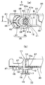
- FIG. 1 It is a perspective view which shows one Embodiment of the assembly
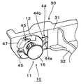
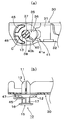
- a state in which the locking leg is inserted into the insertion position is shown, (a) is a plan view thereof, and (b) is a sectional view taken along the line BB of (a).
- a state in which the locking leg is fixed at a fixed position is shown, (a) is a plan view thereof, and (b) is a sectional view.
- this clip / attachment member assembly structure supports, for example, an exterior member 5 disposed on the outside of a member 1 to be attached such as a vehicle body panel.
- the mounting member 30 forming the support bracket is mounted on the mounted member 1 via the clip 10.
- the attachment member 30 may be a garnish or a trim board, and is not particularly limited.
- the clip 10 used for the assembly structure in this embodiment is a so-called two-piece clip including a grommet 11 and a pin 15 inserted into the grommet 11.
- the grommet 11 includes an annular flange portion 12 having a pin insertion hole 12a at the center, and a plurality of locking legs 13 extending from the periphery of the pin insertion hole 12a on one side of the flange portion 12.
- the plurality of locking legs 13 are formed by dividing a cylindrical portion provided on one surface of the flange portion 12 into a plurality of portions via a slit 13a, and can be bent.
- the pin 15 includes a disk-shaped head portion 16 and a shaft portion 17 that is suspended from the center of one surface of the head portion 16.
- a rib 18 that enters the slit 13 a of the grommet 11 is formed on the outer periphery of the shaft portion 17, a temporary fixing claw 18 a is formed in the middle of the rib 18, and an annular protrusion is formed at the tip of the shaft portion 17. 17a is projected.
- the temporarily fixing claw 18a engages with the back side periphery of the pin insertion hole 12a, and the insertion hole 35 (described later) of the attachment member 30 and the attached member 1
- the pin 15 is temporarily fixed to the grommet 11 without increasing the diameter of the locking leg 13 so that the locking leg 13 can be inserted into the mounting hole 3 (see FIG. 3B).
- a projection (not shown) inside the locking leg 13 is pressed by the shaft portion 17 and the locking leg 13 is expanded to expand its diameter.
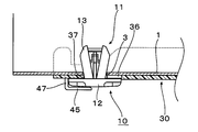
- the mounting member 30 of this embodiment is fixed to the mounted member 1 and functions as a support bracket for the exterior member 5.
- the mounting member 30 is fixed to the mounted member 1 and extends in a predetermined direction, and has a predetermined shape from one end in the length direction of the base portion 31 toward the exterior member 5.
- a projecting support portion 32 and an elastic member 33 fixed to the distal end surface of the support portion 32 are provided.
- an insertion hole 35 into which the locking leg 13 of the clip 10 is inserted is formed at the other end in the length direction of the base portion 31.
- This insertion hole 35 communicates with the insertion position 36 in which the locking leg 13 of the clip 10 can be inserted and the insertion position 36, and the locking leg 13 extends in a direction perpendicular to the insertion direction of the locking leg 13. It has a fixed position 37 that is movable and holds the locking leg 13 at a predetermined position.
- an insertion position 36 is provided on the support portion 32 side, a fixed position 37 is provided in a direction that is connected to the support portion 32 and moves away from the support portion 32.
- the locking leg 13 can be moved in the direction of arrow A (see FIGS. 1 and 3 (a)) orthogonal to the insertion direction to be arranged at the fixed position 37.
- the inner circumference on the insertion position 36 side and the inner circumference on the fixed position 37 side of the insertion hole 35 are arcuate in conformity with the outer circumference of the locking leg 13 of the clip 10.
- a pair of elastic pieces 40, 40 that are deflectable between the insertion position 36 and the fixing position 37 on both sides of the insertion hole 35 along the moving direction (arrow A direction) of the locking leg 13. Are extended in a C shape.
- a pair of relief grooves 38, 38 are formed for enabling the pair of elastic pieces 40, 40 to bend outward.
- the pair of elastic pieces 40, 40 has an opening angle at which the locking leg 13 can be inserted into the insertion position 36 of the insertion hole 35, and the tip thereof is positioned at the fixed position 37.
- the distance D1 between the tips of the pair of elastic pieces 40, 40 is at least as large as the outer diameter of the locking leg 13 as shown in FIG. Is set too small.
- the locking leg 13 in a state where the locking leg 13 is inserted into the insertion position 36, the locking leg 13 abuts against the inner surfaces 40 a, 40 a of the elastic piece 40 (see FIG. 3A), and at the fixed position 37.
- the front end surface 40b of the elastic piece 40 comes into contact with the outer periphery thereof (see FIG. 4A).
- the pair of elastic pieces 40, 40 allow the locking leg 13 to be inserted from the insertion position 36 of the insertion hole 35, and when the locking leg 13 is moved to the fixed position 37, the inner surface 40a thereof
- the latching leg 13 is elastically restored when it reaches the fixed position 37, and is closed again in the shape of a letter C. It is comprised so that the outer periphery of the latching leg 13 may be contact
- a stepped portion 41 having a predetermined height protrudes from the attachment member 30 on the clip insertion direction side and at the periphery of the insertion position 36 of the insertion hole 35.
- the step portion 41 of this embodiment is substantially U-shaped when viewed from the clip insertion direction side (front side) of the mounting member 30, and both side portions 41 a and 41 a extend toward the insertion position 36.
- the tips of the side portions 41a and 41a of the step portion 41 are configured to engage with the periphery of the flange portion 12 (see FIGS. 4A and 4B).
- the stepped portion engages with the flange portion periphery only needs to be engaged so that the stepped portion 41 abuts against the outer periphery of the flange portion 12 when the clip 10 is pulled to the insertion position 36 side. In the state shown in FIG. 4A, there may be a gap between the flange portion 12 and the tip of the step portion 41.
- the mounting member 30 is disposed above the surface of the flange portion 12, and the locking leg 13 is removed.
- a presser piece 45 that restricts movement in the direction is provided.
- a pair of arc-shaped through holes 46, 46 are formed on the outer peripheral edge of the insertion hole 35 of the attachment member 30 on the fixed position 37 side, and the front peripheral edge of each through hole 46 is formed.
- Support walls 47 and 47 are erected at a predetermined height from (the peripheral edge away from the fixed position 37).
- a pair of arc-shaped presser pieces 45, 45 are extended from the upper ends of the support walls 47, 47 so as to cover the through holes 46, 46. 4B, the distance D2 from the clip insertion side surface of the mounting member 30 to the inner surface of the pressing piece 45 is set to be at least larger than the thickness of the flange portion 12 of the clip 10, and The flange portion 12 is received between the surface of the member 30 and the presser piece 45, and the presser piece 45 is arranged above the surface of the flange portion 12.
- the pin 15 is inserted partway into the grommet 11, the temporary fixing claw 18 a is engaged with the rear peripheral edge of the pin insertion hole 12 a, and the pin 15 is temporarily fixed to the grommet 11 without expanding the locking leg 13.
- the locking leg 13 of the clip 10 is moved in the direction of arrow A (see FIGS. 1 and 3A) while grasping the head 16 of the pin 15 and lightly pushing the clip 10 in.
- the flange portion 12 rides on the step portion 41, the front portion in the moving direction of the flange portion 12 is inclined as shown in FIG. 3 (b).
- the clip 10 is prevented from returning to the insertion position 36 of the locking leg 13 by the pair of elastic pieces 40, 40 which are non-return means, and the flange portion 12 is held by the holding piece 45. Since the stop leg 13 is held out, the clip 10 can be firmly held at the fixing position 37 of the insertion hole 35 by both. As a result, even if an indentation force is applied from the opposite side of the insertion direction of the clip 10 or a torsional force is applied to the flange portion 12 and an unexpected external force or the like is applied to the clip 10, the clip 10 The clip 10 can be reliably assembled to the mounting member 30 without falling off.
- FIG. 5 shows a state in which the clip 10 is assembled to the attachment member 30.
- the attachment member 30 can be simply operated by inserting the locking leg 13 of the clip 10 from the insertion position 36 of the insertion hole 35 and moving it to the fixing position 37.
- the clip 10 can be assembled to the assembly, and the assembly workability can be improved. Further, since the locking leg 13 of the clip 10 only needs to be lightly pushed into the insertion position 36 of the insertion hole 35 and does not need to be pushed in strongly as in the cited documents 1 and 2, the assembly work can be performed smoothly. .
- the pair of elastic pieces 40, 40 constituting the check means are extended toward the axis C of the locking leg 13 when the distal ends thereof are located at the fixed position 37 ( (See FIG. 4 (a)). Therefore, for example, even when the outer diameter of the locking leg 13 is slightly changed, the locking leg 13 can come into contact with the outer periphery of the locking leg 13 when trying to move to the fixed position 37. The re-movement of the leg 13 to the insertion position 36 can be reliably controlled.
- the pair of elastic pieces 40, 40 are extended in a letter C shape, as described above, when the locking leg 13 moves from the insertion position 36 to the fixed position 37, the pair of elastic pieces 40 is provided. , 40 is moved while being pushed and spread outward, it is not necessary to move the locking leg 13 with a strong force, and the locking leg 13 can be moved smoothly with a relatively light force. it can. Further, when the locking leg 13 is disposed at the fixed position 37, the tip surfaces 40b of the pair of C-shaped elastic pieces 40, 40 abut on the outer periphery of the locking leg 13 in a balanced manner. The re-movement of the leg 13 can be more reliably regulated and held firmly.
- the flange portion 12 when the locking leg 13 is inserted into the insertion hole 35, the flange portion 12 that has ridden on the step portion 41 is tilted downward in the moving direction (FIG. 3B). )), The flange portion 12 can be easily buried under the presser piece 45, and the assembling workability of the clip 10 can be improved. Further, when the flange portion 12 moves to the fixed position 37, as shown in FIGS. 4A and 5, both side portions 41a and 41a of the step portion 41 engage with the peripheral edge of the flange portion 12, so that the locking leg 13 is engaged. The movement to the insertion position 36 can be more reliably regulated.
- the locking leg 13 protruding from the back side of the mounting hole 3 is aligned with the mounting hole 3 of the mounted member 1 as shown in FIG.
- the mounting member 30 is inserted into contact with the surface of the mounted member 1.
- the pin 15 is pushed deeply into the grommet 11 to increase the diameter of the plurality of locking legs 13 and engage with the rear peripheral edge of the mounting hole 3.
- the attachment member 30 can be fixed to the attachment member 1.
- the exterior member 5 (see FIG. 1) disposed outside the attached member 1 is supported by the elastic member 33 at the distal end of the support portion 32 of the attachment member 30 fixed to the attached member 1, so that there is no backlash. It is designed to be held firmly.
- the attachment hole 3 is attached after the clip 10 is assembled to the attachment member 30.
- the mounting member 30 can be fixed to the mounted member 1 by a simple operation of inserting the locking leg 13 and pushing the pin 15 deeply, and the workability can be improved. Further, the insertion resistance of the locking leg 13 into the mounting hole 3 can be reduced.
- the two-piece clip can be assembled in advance to the attachment member 30, so that the assembly operation can be performed easily and quickly.
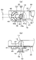
- the structure of the check means is different from that in the above embodiment. That is, as shown in FIGS. 7A and 8A, the insertion hole 35 of the mounting member 30 in this embodiment has a long hole shape extending in one direction, and one end side in the length direction ( The support portion 32 side) forms an insertion position 36, the other end in the length direction forms a fixed position 37, and the insertion position 36 and the fixed position 37 communicate with each other so that the locking leg 13 can be moved.
- a pair of slits 43, 43 extending toward the support portion 32 are formed on the inner periphery of the insertion hole 35 on the long hole-like insertion hole 35, and elasticity that can be bent through the pair of slits 43, 43.
- a claw piece 44 is formed and extends to the fixed position 37 side.
- a protruding portion 44 a having a predetermined height is projected from the free end of the elastic claw piece 44 on the clip insertion direction side, and this is pressed against the flange portion 12 when the clip is inserted.
- the distal end surface 44b of the elastic claw piece 44 is configured to engage with the outer periphery of the flange portion 12 when the locking leg 13 is moved to the fixed position 37 by bending in the insertion direction (see FIG. 7B). (See FIGS. 8A and 8B).
- the elastic claw piece 44 constitutes “a check means” in the present invention.
- the clip 10 can be assembled to the attachment member 30 as shown in FIG. According to this embodiment, when the locking leg 13 moves to the fixing position 37 of the insertion hole 35, the elastic claw piece 44 that forms a check means engages with the outer periphery of the flange portion 12 having a larger diameter. The re-movement of the locking leg 13 to the insertion position 36 can be reliably restricted.
- FIG. 10 and FIG. 11 show still another embodiment of the assembly structure of the clip and the mounting member in the present invention. Note that substantially the same parts as those of the above-described embodiment are denoted by the same reference numerals, and description thereof is omitted.
- the structure of the check means is different from that in the above embodiment. That is, in the embodiment shown in FIGS. 1 to 6, the pair of C-shaped elastic pieces 40, 40 constitutes a check means, but in this embodiment, the check means is a single elastic piece 40. The point made up of is different.
- one escape groove between the insertion position 36 and the fixed position 37 on one side of the insertion hole 35 along the movement direction of the locking leg 13 is provided.
- the elastic piece 40 which can be bent is extended from the inner periphery by the side of the insertion position 36 of this escape groove 38. As shown in FIG. Further, the elastic piece 40 extends toward the axis C of the locking leg 13 when the tip thereof is located at the fixed position 37 (see FIG. 11A), the tip of the elastic piece 40, and the insertion hole 35.
- the distance D3 (see FIG. 10A) with one side of the opposite side of the elastic piece is set to be at least smaller than the outer diameter of the locking leg 13.
- the locking leg 13 is inserted from the insertion position 36 of the insertion hole 35, and the locking leg 13 is moved to the fixed position 37 while the elastic piece 40 is bent toward the escape groove 38. Accordingly, the return of the locking leg 13 is prevented by the elastic piece 40 which is a check means, and the clip 10 can be assembled to the mounting member 30 in a state where the locking leg 13 is held out.
- the clip 10 used for each embodiment demonstrated above is a 2 piece clip which consists of the grommet 11 and the pin 15, it is not limited to this, What is necessary is just a clip provided with a flange part and a locking leg.
- it may be a clip or the like provided with a flange portion, a stem portion extending from one side of the flange portion, and a pair of locking legs extending like a foot from both ends of the stem portion.
Landscapes
- Engineering & Computer Science (AREA)
- General Engineering & Computer Science (AREA)
- Mechanical Engineering (AREA)
- Insertion Pins And Rivets (AREA)
- Connection Of Plates (AREA)
Abstract
Priority Applications (3)
| Application Number | Priority Date | Filing Date | Title |
|---|---|---|---|
| JP2010536715A JP5081980B2 (ja) | 2008-11-05 | 2009-08-07 | クリップと取付部材との組付構造 |
| CN2009801442764A CN102203438A (zh) | 2008-11-05 | 2009-08-07 | 卡子与安装目标件的安装结构 |
| US12/998,573 US20110219588A1 (en) | 2008-11-05 | 2009-08-07 | Attachment structure of clip and mounting-subject member |
Applications Claiming Priority (2)
| Application Number | Priority Date | Filing Date | Title |
|---|---|---|---|
| JP2008284269 | 2008-11-05 | ||
| JP2008-284269 | 2008-11-05 |
Publications (1)
| Publication Number | Publication Date |
|---|---|
| WO2010052960A1 true WO2010052960A1 (fr) | 2010-05-14 |
Family
ID=42152770
Family Applications (1)
| Application Number | Title | Priority Date | Filing Date |
|---|---|---|---|
| PCT/JP2009/064019 Ceased WO2010052960A1 (fr) | 2008-11-05 | 2009-08-07 | Structure permettant d’assembler une attache et un élément de montage |
Country Status (4)
| Country | Link |
|---|---|
| US (1) | US20110219588A1 (fr) |
| JP (1) | JP5081980B2 (fr) |
| CN (1) | CN102203438A (fr) |
| WO (1) | WO2010052960A1 (fr) |
Cited By (3)
| Publication number | Priority date | Publication date | Assignee | Title |
|---|---|---|---|---|
| JP2012202450A (ja) * | 2011-03-24 | 2012-10-22 | Kumi Kasei Kk | クリップ受け構造 |
| JP2015137072A (ja) * | 2014-01-24 | 2015-07-30 | 富士重工業株式会社 | 車両用パッド部材の取付構造 |
| JP2023125127A (ja) * | 2022-02-28 | 2023-09-07 | 矢崎総業株式会社 | 外装部材、及び、ワイヤハーネス |
Families Citing this family (10)
| Publication number | Priority date | Publication date | Assignee | Title |
|---|---|---|---|---|
| US20150375799A1 (en) * | 2014-06-30 | 2015-12-31 | GM Global Technology Operations LLC | Elastically averaged alignment systems and methods |
| US9746013B2 (en) * | 2015-03-11 | 2017-08-29 | Fca Us Llc | Spring steel wire harness clip |
| WO2018060964A1 (fr) * | 2016-09-29 | 2018-04-05 | Magna Exteriors Inc. | Conception de positionnement et de retenue d'élément de fixation pour s'adapter à l'expansion et à la contraction de pièces |
| US10288098B2 (en) * | 2016-11-04 | 2019-05-14 | Newfrey Llc | Pin and grommet fastener accommodating two directional offset and related methods |
| US11692570B2 (en) | 2016-11-04 | 2023-07-04 | Newfrey Llc | Pin and grommet fastener accommodating two directional offset and related methods |
| US10246031B1 (en) * | 2017-09-15 | 2019-04-02 | GM Global Technology Operations LLC | Self-retaining angled fastening device for securing a component to a panel in a vehicle |
| US10408248B1 (en) | 2018-09-05 | 2019-09-10 | Newfrey Llc | Sealing pin and grommet fastener accommodating two directional offset |
| CN110425206B (zh) * | 2019-06-28 | 2020-12-22 | 潍柴动力股份有限公司 | 子母扣结构及车内饰件 |
| EP3904705B1 (fr) * | 2020-05-01 | 2024-10-09 | HellermannTyton s.a.s. | Support pour insert et ensemble comprenant le support et l'insert |
| US20240067068A1 (en) * | 2022-08-26 | 2024-02-29 | Faurecia Interior Systems, Inc. | Vehicle interior panel and method of manufacture |
Citations (7)
| Publication number | Priority date | Publication date | Assignee | Title |
|---|---|---|---|---|
| JPS63123811U (fr) * | 1987-02-04 | 1988-08-11 | ||
| JPH01166806U (fr) * | 1988-04-28 | 1989-11-22 | ||
| JPH0484905U (fr) * | 1990-11-30 | 1992-07-23 | ||
| JPH0587318U (ja) * | 1991-12-02 | 1993-11-26 | 株式会社ニフコ | クリップ |
| JP2000071766A (ja) * | 1998-08-28 | 2000-03-07 | T S Tec Kk | 車両用内装部品のクリップ取付座 |
| JP2002106531A (ja) * | 2000-09-27 | 2002-04-10 | Nifco Inc | クリップ |
| JP2003314516A (ja) * | 2002-04-17 | 2003-11-06 | Shigeru Co Ltd | 自動車トリムの取付構造 |
Family Cites Families (22)
| Publication number | Priority date | Publication date | Assignee | Title |
|---|---|---|---|---|
| US2033100A (en) * | 1932-10-20 | 1936-03-03 | Johns Manville | Structural assembly |
| US3249973A (en) * | 1962-12-21 | 1966-05-10 | United Carr Inc | Trim pad mounting fastener |
| GB1066861A (en) * | 1963-02-22 | 1967-04-26 | Carr Fastener Co Ltd | Clip for fastening together two apertured panels |
| US3351974A (en) * | 1965-12-30 | 1967-11-14 | United Carr Inc | Self-securing grommet |
| US4405272A (en) * | 1981-03-11 | 1983-09-20 | Phillips Plastics Corporation | Two-piece fastener with front shoulder |
| JPS6215393U (fr) * | 1985-07-12 | 1987-01-29 | ||
| JPH0218404Y2 (fr) * | 1986-09-30 | 1990-05-23 | ||
| JP2578069Y2 (ja) * | 1991-03-11 | 1998-08-06 | 株式会社 ニフコ | グロメット |
| US5163795A (en) * | 1992-04-09 | 1992-11-17 | Illionis Tool Works, Inc. | Front mounted rivet with interlocked drive pin |
| US5507610A (en) * | 1994-07-27 | 1996-04-16 | Emhart Inc. | Refusable fastener including a pin and grommet |
| US5707097A (en) * | 1994-11-03 | 1998-01-13 | Horwill; Rodney Edward | Fastener assemblies for vehicle accessories |
| JP3914710B2 (ja) * | 2001-01-15 | 2007-05-16 | 株式会社ニフコ | 留め具 |
| US6594870B1 (en) * | 2001-01-22 | 2003-07-22 | Johnson Controls Technology Company | Panel fastener |
| DE10358683B4 (de) * | 2003-12-12 | 2005-11-17 | A. Raymond & Cie | Vorrichtung zum Verbinden eines Trägerteils und eines Anbauteils |
| JP2006088985A (ja) * | 2004-09-27 | 2006-04-06 | Toyoda Gosei Co Ltd | 頭部保護エアバッグ装置 |
| WO2007094453A1 (fr) * | 2006-02-17 | 2007-08-23 | Piolax Inc. | Piece de fixation |
| DE102006043060B4 (de) * | 2006-03-13 | 2011-07-21 | A. Raymond Et Cie | Befestigungsanordnung |
| JP4545711B2 (ja) * | 2006-06-01 | 2010-09-15 | ポップリベット・ファスナー株式会社 | クリップ |
| JP2009008249A (ja) * | 2007-05-30 | 2009-01-15 | Piolax Inc | 2ピースクリップ |
| US7927050B2 (en) * | 2007-05-30 | 2011-04-19 | Piolax Inc. | Interior part mounting clip |
| DE102008033307A1 (de) * | 2008-07-16 | 2010-01-21 | Newfrey Llc, Newark | Befestigungsvorrichtung |
| US8291553B2 (en) * | 2009-08-11 | 2012-10-23 | Toyota Motor Engineering & Manufacturing North America, Inc. | Trim panel having a clip retention feature |
-
2009
- 2009-08-07 WO PCT/JP2009/064019 patent/WO2010052960A1/fr not_active Ceased
- 2009-08-07 CN CN2009801442764A patent/CN102203438A/zh active Pending
- 2009-08-07 US US12/998,573 patent/US20110219588A1/en not_active Abandoned
- 2009-08-07 JP JP2010536715A patent/JP5081980B2/ja not_active Expired - Fee Related
Patent Citations (7)
| Publication number | Priority date | Publication date | Assignee | Title |
|---|---|---|---|---|
| JPS63123811U (fr) * | 1987-02-04 | 1988-08-11 | ||
| JPH01166806U (fr) * | 1988-04-28 | 1989-11-22 | ||
| JPH0484905U (fr) * | 1990-11-30 | 1992-07-23 | ||
| JPH0587318U (ja) * | 1991-12-02 | 1993-11-26 | 株式会社ニフコ | クリップ |
| JP2000071766A (ja) * | 1998-08-28 | 2000-03-07 | T S Tec Kk | 車両用内装部品のクリップ取付座 |
| JP2002106531A (ja) * | 2000-09-27 | 2002-04-10 | Nifco Inc | クリップ |
| JP2003314516A (ja) * | 2002-04-17 | 2003-11-06 | Shigeru Co Ltd | 自動車トリムの取付構造 |
Cited By (4)
| Publication number | Priority date | Publication date | Assignee | Title |
|---|---|---|---|---|
| JP2012202450A (ja) * | 2011-03-24 | 2012-10-22 | Kumi Kasei Kk | クリップ受け構造 |
| JP2015137072A (ja) * | 2014-01-24 | 2015-07-30 | 富士重工業株式会社 | 車両用パッド部材の取付構造 |
| JP2023125127A (ja) * | 2022-02-28 | 2023-09-07 | 矢崎総業株式会社 | 外装部材、及び、ワイヤハーネス |
| JP7803741B2 (ja) | 2022-02-28 | 2026-01-21 | 矢崎総業株式会社 | 外装部材、及び、ワイヤハーネス |
Also Published As
| Publication number | Publication date |
|---|---|
| JPWO2010052960A1 (ja) | 2012-04-05 |
| CN102203438A (zh) | 2011-09-28 |
| US20110219588A1 (en) | 2011-09-15 |
| JP5081980B2 (ja) | 2012-11-28 |
Similar Documents
| Publication | Publication Date | Title |
|---|---|---|
| JP5081980B2 (ja) | クリップと取付部材との組付構造 | |
| JP5027919B2 (ja) | クリップ | |
| CN1936345B (zh) | 轴固定结构 | |
| JP2002036873A (ja) | サンバイザーホルダー | |
| WO2010007828A1 (fr) | Dispositif de fixation | |
| JP2009047305A (ja) | 固定具、被固定部材の固定構造、被固定部材の固定方法及び固定具の固定解除方法 | |
| KR20080004379A (ko) | 클립 | |
| JP2009041673A (ja) | クリップ及び支持部材 | |
| JP4722458B2 (ja) | 車両アクセサリ固定用金属クリップ及びそれを用いた車両アクセサリ取付け構造 | |
| WO2009093496A1 (fr) | Attache | |
| JP2014241666A (ja) | コルゲートクランプおよびコルゲートクランプ付きワイヤーハーネス | |
| JP5085427B2 (ja) | クリップ | |
| JP5210207B2 (ja) | クリップと取付部材との組付構造 | |
| JP4638389B2 (ja) | クリップ | |
| JP2009257508A (ja) | 2ピースクリップ | |
| JP5095550B2 (ja) | クリップ | |
| JP4675847B2 (ja) | 2ピースクリップ | |
| JP2019100440A (ja) | プラスチックファスナー | |
| JP2008095880A (ja) | 部品の取付構造 | |
| JP2009030796A (ja) | 内装部品の取付構造 | |
| JP3748922B2 (ja) | 防振クリップ | |
| JP2003002102A (ja) | クリップ及びクリップ付き自動車部品 | |
| JP5892044B2 (ja) | 部品の取付構造 | |
| JP2023009080A (ja) | 車両内装部材の取付装置及び車両内装部材の取付装置用の取付部材 | |
| JPH08135645A (ja) | 端末部材およびその組付方法 |
Legal Events
| Date | Code | Title | Description |
|---|---|---|---|
| WWE | Wipo information: entry into national phase |
Ref document number: 200980144276.4 Country of ref document: CN |
|
| 121 | Ep: the epo has been informed by wipo that ep was designated in this application |
Ref document number: 09824660 Country of ref document: EP Kind code of ref document: A1 |
|
| DPE1 | Request for preliminary examination filed after expiration of 19th month from priority date (pct application filed from 20040101) | ||
| WWE | Wipo information: entry into national phase |
Ref document number: 2010536715 Country of ref document: JP |
|
| WWE | Wipo information: entry into national phase |
Ref document number: 12998573 Country of ref document: US Ref document number: 3039/CHENP/2011 Country of ref document: IN |
|
| NENP | Non-entry into the national phase |
Ref country code: DE |
|
| 122 | Ep: pct application non-entry in european phase |
Ref document number: 09824660 Country of ref document: EP Kind code of ref document: A1 |