WO2010053090A1 - Procédé de séchage de matériau de fines particules et dispositif de séchage de matériau de fines particules - Google Patents
Procédé de séchage de matériau de fines particules et dispositif de séchage de matériau de fines particules Download PDFInfo
- Publication number
- WO2010053090A1 WO2010053090A1 PCT/JP2009/068828 JP2009068828W WO2010053090A1 WO 2010053090 A1 WO2010053090 A1 WO 2010053090A1 JP 2009068828 W JP2009068828 W JP 2009068828W WO 2010053090 A1 WO2010053090 A1 WO 2010053090A1
- Authority
- WO
- WIPO (PCT)
- Prior art keywords
- heater
- regeneration
- temperature
- gas
- drying
- Prior art date
- Legal status (The legal status is an assumption and is not a legal conclusion. Google has not performed a legal analysis and makes no representation as to the accuracy of the status listed.)
- Ceased
Links
Images


Classifications
-
- B—PERFORMING OPERATIONS; TRANSPORTING
- B01—PHYSICAL OR CHEMICAL PROCESSES OR APPARATUS IN GENERAL
- B01D—SEPARATION
- B01D53/00—Separation of gases or vapours; Recovering vapours of volatile solvents from gases; Chemical or biological purification of waste gases, e.g. engine exhaust gases, smoke, fumes, flue gases, aerosols
- B01D53/02—Separation of gases or vapours; Recovering vapours of volatile solvents from gases; Chemical or biological purification of waste gases, e.g. engine exhaust gases, smoke, fumes, flue gases, aerosols by adsorption, e.g. preparative gas chromatography
- B01D53/06—Separation of gases or vapours; Recovering vapours of volatile solvents from gases; Chemical or biological purification of waste gases, e.g. engine exhaust gases, smoke, fumes, flue gases, aerosols by adsorption, e.g. preparative gas chromatography with moving adsorbents, e.g. rotating beds
-
- B—PERFORMING OPERATIONS; TRANSPORTING
- B01—PHYSICAL OR CHEMICAL PROCESSES OR APPARATUS IN GENERAL
- B01D—SEPARATION
- B01D53/00—Separation of gases or vapours; Recovering vapours of volatile solvents from gases; Chemical or biological purification of waste gases, e.g. engine exhaust gases, smoke, fumes, flue gases, aerosols
- B01D53/26—Drying gases or vapours
- B01D53/261—Drying gases or vapours by adsorption
-
- B—PERFORMING OPERATIONS; TRANSPORTING
- B29—WORKING OF PLASTICS; WORKING OF SUBSTANCES IN A PLASTIC STATE IN GENERAL
- B29B—PREPARATION OR PRETREATMENT OF THE MATERIAL TO BE SHAPED; MAKING GRANULES OR PREFORMS; RECOVERY OF PLASTICS OR OTHER CONSTITUENTS OF WASTE MATERIAL CONTAINING PLASTICS
- B29B13/00—Conditioning or physical treatment of the material to be shaped
- B29B13/06—Conditioning or physical treatment of the material to be shaped by drying
- B29B13/065—Conditioning or physical treatment of the material to be shaped by drying of powder or pellets
-
- B—PERFORMING OPERATIONS; TRANSPORTING
- B29—WORKING OF PLASTICS; WORKING OF SUBSTANCES IN A PLASTIC STATE IN GENERAL
- B29B—PREPARATION OR PRETREATMENT OF THE MATERIAL TO BE SHAPED; MAKING GRANULES OR PREFORMS; RECOVERY OF PLASTICS OR OTHER CONSTITUENTS OF WASTE MATERIAL CONTAINING PLASTICS
- B29B9/00—Making granules
- B29B9/16—Auxiliary treatment of granules
-
- F—MECHANICAL ENGINEERING; LIGHTING; HEATING; WEAPONS; BLASTING
- F26—DRYING
- F26B—DRYING SOLID MATERIALS OR OBJECTS BY REMOVING LIQUID THEREFROM
- F26B17/00—Machines or apparatus for drying materials in loose, plastic, or fluidised form, e.g. granules, staple fibres, with progressive movement
- F26B17/12—Machines or apparatus for drying materials in loose, plastic, or fluidised form, e.g. granules, staple fibres, with progressive movement with movement performed solely by gravity, i.e. the material moving through a substantially vertical drying enclosure, e.g. shaft
- F26B17/14—Machines or apparatus for drying materials in loose, plastic, or fluidised form, e.g. granules, staple fibres, with progressive movement with movement performed solely by gravity, i.e. the material moving through a substantially vertical drying enclosure, e.g. shaft the materials moving through a counter-current of gas
-
- F—MECHANICAL ENGINEERING; LIGHTING; HEATING; WEAPONS; BLASTING
- F26—DRYING
- F26B—DRYING SOLID MATERIALS OR OBJECTS BY REMOVING LIQUID THEREFROM
- F26B21/00—Arrangements for supplying or controlling air or other gases for drying solid materials or objects
- F26B21/30—Controlling, e.g. regulating, parameters of gas supply
-
- F—MECHANICAL ENGINEERING; LIGHTING; HEATING; WEAPONS; BLASTING
- F26—DRYING
- F26B—DRYING SOLID MATERIALS OR OBJECTS BY REMOVING LIQUID THEREFROM
- F26B9/00—Machines or apparatus for drying solid materials or objects at rest or with only local agitation; Domestic airing cupboards
- F26B9/06—Machines or apparatus for drying solid materials or objects at rest or with only local agitation; Domestic airing cupboards in stationary drums or chambers
- F26B9/063—Machines or apparatus for drying solid materials or objects at rest or with only local agitation; Domestic airing cupboards in stationary drums or chambers for drying granular material in bulk, e.g. grain bins or silos with false floor
-
- B—PERFORMING OPERATIONS; TRANSPORTING
- B01—PHYSICAL OR CHEMICAL PROCESSES OR APPARATUS IN GENERAL
- B01D—SEPARATION
- B01D2251/00—Reactants
- B01D2251/30—Alkali metal compounds
- B01D2251/302—Alkali metal compounds of lithium
-
- B—PERFORMING OPERATIONS; TRANSPORTING
- B01—PHYSICAL OR CHEMICAL PROCESSES OR APPARATUS IN GENERAL
- B01D—SEPARATION
- B01D2253/00—Adsorbents used in seperation treatment of gases and vapours
- B01D2253/10—Inorganic adsorbents
- B01D2253/106—Silica or silicates
- B01D2253/108—Zeolites
-
- B—PERFORMING OPERATIONS; TRANSPORTING
- B01—PHYSICAL OR CHEMICAL PROCESSES OR APPARATUS IN GENERAL
- B01D—SEPARATION
- B01D2255/00—Catalysts
- B01D2255/20—Metals or compounds thereof
- B01D2255/207—Transition metals
- B01D2255/20707—Titanium
-
- B—PERFORMING OPERATIONS; TRANSPORTING
- B01—PHYSICAL OR CHEMICAL PROCESSES OR APPARATUS IN GENERAL
- B01D—SEPARATION
- B01D2257/00—Components to be removed
- B01D2257/80—Water
Definitions
- the gas blown from the blower is heated by passing through a heater, supplied into a drying hopper that stores the powder material, and the powder material is dried.
- the present invention relates to a method and an improvement of a drying apparatus for granular material.
- a drying device for powder material a drying hopper that receives the powder, a drying blower (blower) for blowing a drying gas to the drying hopper, and a drying gas blown to the drying hopper are heated.
- the thing provided with the heater (heater) for this is known.
- outside air is taken in by a blower, heated by a heater, supplied into the drying hopper, passed through the granular material layer stored in the drying hopper, and the upper part of the drying hopper The particulate material is dried by exhausting from the exhaust port.
- the drying apparatus as described above is configured to heat air containing moisture in the atmosphere and supply it to the drying hopper, the drying efficiency is relatively poor.
- an adsorber dehumidification unit for removing a wet component (moisture) in the dry gas exhausted from the dry hopper is connected to the dry hopper via a gas circulation path.
- a drying gas dehumidified in the adsorber is circulated and supplied to a drying hopper.
- the granular material stored in the drying hopper is not supplied all at once for the next processing step such as a molding machine or a processing machine, but molded.
- the next processing step such as a molding machine or a processing machine, but molded.
- an appropriate amount is discharged from the lower discharge port.
- new undried powder material is charged into the dry hopper from the upper charging port or the like.
- the drying apparatus generally includes a drying hopper that receives the granular material, a drying blower for blowing dry gas, an adsorber for removing wet components in the drying gas, and heating the drying gas.
- the regeneration line is provided with a regeneration blower for blowing regeneration gas to the adsorber and a regeneration heater for heating the regeneration gas.
- the connecting pipe is provided with a discharge temperature sensor for detecting the temperature of the drying gas discharged from the drying hopper. When the discharge temperature sensor detects a stop temperature, a start trigger input program and a stop program are provided. The temperature stop mode is activated.
- the blower drive mechanism (each heater, each blower, etc.) is stopped every time the discharge temperature sensor detects the stop temperature, while the trigger signal of the start trigger input program is periodically sent to the blower drive mechanism. Given to. Thus, it is described that the efficiency of the entire drying apparatus can be increased and the running cost can be reduced.
- the blower driving mechanism is stopped by first stopping the rotation motors of the drying heater, the regenerative heater, and the adsorber, and after a predetermined time has elapsed.
- the mode which stops a dry blower and a regeneration blower is illustrated. According to this, since the drying gas and the regeneration gas are blown to the drying heater and the regeneration heater for a predetermined time after stopping, it is possible to prevent the drying heater and the regeneration heater from being damaged. Has been.
- the blower driving mechanism is stopped and periodically started by detecting the stop temperature of the discharge temperature sensor.
- the exhaust temperature is considered to be close to the stop temperature immediately after the stop, Since the stop temperature is reached immediately and the stop is performed, the energy loss at the time of starting and stopping may increase, and further improvement has been desired from the viewpoint of energy saving.
- the said drying apparatus in order to prevent damage to a drying heater and a regenerative heater as mentioned above, it is set as the aspect which stops each blower after stopping each heater and predetermined time passes. According to this, it is possible to prevent damage to each heater, but if the predetermined time is too long, the heater is cooled too much, and the temperature of the gas supplied to the drying hopper through the drying heater is reduced. Since it falls rapidly, the temperature of the heat-dried granular material in the drying hopper will fall.
- the predetermined time is too short, the temperature in the casing of the heater is not sufficiently lowered, but the blower is stopped for a short time due to the inertia of the blower after the blower is stopped (the rotation of the blower due to the moment of inertia).
- a gas having a temperature higher than the set temperature is blown into the drying hopper, and the powder may be overheated. Therefore, the powder may be deteriorated.
- the predetermined time may be insufficient or too long. It was difficult.
- the present invention has been made in view of the above circumstances, and is capable of reducing adverse effects on the granular material in the dry hopper and reducing the energy consumption of the granular material, and the granular material.
- the object is to provide a drying device.
- the method for drying granular material comprises heating a gas blown from a blower through a heater and storing the granular material in a drying hopper.
- the drying method of the granular material for supplying and drying the granular material when the temperature indicating the drying treatment state of the granular material in the drying hopper exceeds a preset first threshold, The heater is stopped, and when the temperature of the gas that has passed through the heater in the stopped state falls below a preset second threshold value, the blower is stopped, and then the heater is When the first time has elapsed, the heater and the blower are activated.
- a dehumidifying unit having an adsorbent for dehumidifying a gas exhausted from an exhaust port of the drying hopper is provided in the drying hopper via a gas circulation path.
- the dehumidifying unit of the gas exhausted from the exhaust port and the gas blown from the regenerating blower to the adsorbent after dehumidifying the gas are regenerated.
- a heating regeneration process in which the adsorbent is heated and regenerated, and when the heater is stopped, the regeneration heater is stopped and further stopped.
- the regeneration blower When the temperature of the gas that has passed through the regeneration heater in the state falls below a preset third threshold, the regeneration blower is stopped, and then a predetermined first time has elapsed since the heater was stopped. did Kiniwa, may be activating the regeneration heater and the reproducing blower.
- a dehumidifying unit having an adsorbent for dehumidifying the gas exhausted from the exhaust port of the drying hopper is provided in the drying hopper through a gas circulation path.
- the dehumidifying unit the dehumidifying process of the gas exhausted from the exhaust port, and the gas blown from the regeneration blower to the adsorbent after dehumidifying the gas are provided.
- a heating regeneration step in which the adsorbent is heated and regenerated by passing through a regeneration heater, and the temperature of the gas that has passed through the adsorbent in the heating regeneration step is preset.
- the regeneration heater When the temperature exceeds 4 threshold values, the regeneration heater is stopped, and when the temperature of the gas that has passed through the regeneration heater in the stopped state falls below a preset third threshold value, the regeneration heater is stopped.
- the blower is stopped, then the when the second time from the stop of the reproducing heater predetermined has passed, may be caused to start the reproduction heater and the reproducing blower.
- the drying apparatus of the granular material which concerns on this invention is the drying hopper which stores granular material, the air blower for supplying the heated gas to this drying hopper, and heating
- a drying apparatus for a granular material having a container, a first temperature detection sensor for detecting a temperature indicating a drying treatment state of the granular material in the drying hopper, and a temperature of the gas passing through the heater
- a second temperature detection sensor to detect, and when the detected temperature of the first temperature detection sensor exceeds a preset first threshold, the heater is stopped, and the second temperature detection sensor in the stopped state
- the blower is stopped, and then when the predetermined first time has elapsed since the heater was stopped, the heater and the blower are started.
- a control means for for.
- a dehumidifying unit having an adsorbent for dehumidifying the gas exhausted from the exhaust port of the drying hopper is provided in the drying hopper via a gas circulation path.
- the dehumidifying unit is configured to be connected to the dehumidifying zone for dehumidifying the gas exhausted from the exhaust port through the adsorbent and the adsorbent after dehumidifying the gas.
- the gas blown from the blower is heated and supplied through the regeneration heater, the heating regeneration zone for heating and regenerating the adsorbent, and the temperature of the gas that has passed through the regeneration heater is detected.
- the regeneration heater is stopped, and the detection of the third temperature detection sensor in the stopped state is performed.
- the degree falls below a preset third threshold, the regeneration blower is stopped, and then, when a predetermined first time has elapsed since the stop of the heater, the regeneration heater and the regeneration fan You may make it control to start an air blower.
- a dehumidifying unit having an adsorbent for dehumidifying the gas exhausted from the exhaust port of the drying hopper is provided in the drying hopper through a gas circulation path.
- the dehumidification unit, the gas exhausted from the exhaust port is passed through the adsorbent, the dehumidifying treatment zone for dehumidifying, and the adsorbent after dehumidifying the gas,
- the gas blown from the regenerative blower is heated and supplied through the regenerative heater, and the adsorbent is heated and regenerated, and the temperature of the gas that has passed through the regenerative heater is detected.
- a fourth temperature detection sensor for detecting the temperature of the gas that has passed through the adsorbent in the heating regeneration zone, and the control means controls the fourth temperature detection sensor.
- the regeneration heater is stopped, and further, the detected temperature of the third temperature detection sensor in the stopped state falls below the preset third threshold value.
- the regeneration blower is stopped, and then, when a predetermined second time has elapsed since the stop of the regeneration heater, the regeneration heater and the regeneration blower are controlled to be activated. It may be.
- the heater is stopped and then heated. Since the blower is stopped when the temperature of the gas that has passed through the cooler falls below a predetermined temperature, energy saving can be achieved and overheating of the material can be prevented. That is, according to the discharge amount of the granular material laminated in the dry hopper, the granular material in the dry hopper is in a state where at least the granular material discharged in the lower layer is sufficiently dried.
- the heater and the blower are stopped according to the predetermined condition as described above, so that energy saving can be achieved and the material can be saved. Overheating can be prevented.
- the blower is stopped when the temperature of the gas that has passed through the heater falls below a predetermined temperature after the heater is stopped, energy saving can be achieved, damage to the heater, The adverse effect on the granular material in the dry hopper can be reduced. That is, it is determined whether the heater has been overcooled or undercooled according to the temperature of the gas that has passed through the heater, and when the predetermined temperature, that is, the temperature at which the heater is not overcooled or undercooled, is reached. Since the vessel can be stopped, it is possible to reduce a decrease in temperature of the heated and dried granular material in the drying hopper, deterioration due to overheating of the granular material, and the like.
- the blower is stopped when the temperature of the gas that has passed through the heater falls below a predetermined temperature after the heater is stopped, it is affected by fluctuations in the outside air temperature, etc. The above effects can be surely achieved without any problems. Moreover, since these heaters and blowers are started after a predetermined time has elapsed after being stopped, they are not started immediately after being stopped and energy saving can be achieved efficiently.
- the drying hopper is connected to a dehumidifying unit that performs the dehumidifying treatment step and the heating regeneration step, and the regeneration is performed when the heater is stopped.
- the regeneration blower is stopped, and then the heater.
- the predetermined first time has elapsed since the stop of the operation, if the regeneration heater and the regeneration blower are activated, the following effects can be obtained. That is, since the gas dehumidified in the dehumidifying unit is supplied to the drying hopper via the gas circulation path, for example, the powder material is dried as compared with the case where the outside air is directly heated and supplied.
- the heater of the drying hopper is stopped, the regeneration heater of the dehumidifying unit is stopped, and then the temperature of the gas that has passed through each of the heater and the regeneration heater falls below a predetermined temperature.
- the blower and the regenerative blower are stopped respectively, energy saving can be achieved and, similarly to the above, the adverse effect on the particulate material can be reduced, and it is also affected by fluctuations in the outside air temperature, etc. Without damaging the heater and the regeneration heater.
- a dehumidifying unit that performs the dehumidifying treatment step and the heating regeneration step is connected to the drying hopper, and the adsorbent in the heating regeneration step is used.
- the regeneration heater is stopped, and further, the temperature of the gas that has passed through the regeneration heater in the stopped state is preset to a third value.
- the regeneration fan is stopped when the value falls below a threshold value, and then the regeneration heater and the regeneration fan are activated when a predetermined second time has elapsed since the regeneration heater was stopped. If so, the following effects are produced.
- the heating regeneration step when the temperature of the gas that has passed through the adsorbent reaches a predetermined temperature, the regeneration heater is stopped, and then the temperature of the gas that has passed through the regeneration heater is a predetermined temperature. Since the regeneration blower is stopped when the value falls below the value, energy saving can be achieved. That is, it is possible to discriminate the processing state of the heating and regeneration of the adsorbent based on the temperature of the gas that has passed through the adsorbent, and to stop the regeneration heater and the regeneration blower, thereby saving energy. Further, as described above, after stopping the regeneration heater, the regeneration blower is stopped when the temperature of the gas that has passed through the regeneration heater falls below a predetermined temperature. In addition, the regeneration heater can be prevented from being damaged without being affected by fluctuations in the outside air temperature.
- the drying apparatus for the granular material includes a first temperature detection sensor that detects a temperature indicating a drying treatment state of the granular material in the drying hopper, and a temperature of the gas that has passed through the heater.
- a second temperature detection sensor to detect, and when the detected temperature of the first temperature detection sensor exceeds a preset first threshold, the heater is stopped, and the second temperature detection sensor in the stopped state
- the blower is stopped, and then when the predetermined first time has passed since the heater was stopped, the heater and the blower are started.
- control means for causing the Therefore similarly to the above, energy saving can be achieved, and damage to the heater and adverse effects on the powder material in the drying hopper can be reduced.
- a dehumidifying unit having the dehumidifying treatment zone, the heating regeneration zone, and the third temperature detection sensor is connected to the drying hopper, and the control means
- the control means When the heater is stopped, the regeneration heater is stopped, and when the detected temperature of the third temperature detection sensor in the stopped state falls below a preset third threshold value, the regeneration is performed. If the control is performed so that the regeneration heater and the regeneration blower are activated when a predetermined first time has elapsed since the stop of the heater and then the heater is stopped, the following effects are obtained. Play. That is, similarly to the above, since the gas dehumidified in the dehumidifying unit is supplied to the drying hopper through the gas circulation path, the powder material can be efficiently dried and energy saving can be achieved. Damage to the regenerative heater can be prevented.
- the dehumidifying unit having the dehydrating hopper, the heating regeneration zone, the third temperature detecting sensor, and the fourth temperature detecting sensor in the drying hopper.
- the regeneration heater is stopped, and further, the second heater in the stopped state is stopped.
- the regeneration blower is stopped, and then when a predetermined second time has elapsed since the stop of the regeneration heater, If the control is performed so that the regeneration heater and the regeneration blower are activated, the following effects can be obtained. That is, similarly to the above, since the gas dehumidified in the dehumidifying unit is supplied to the drying hopper through the gas circulation path, the powder material can be efficiently dried and energy saving can be achieved. Damage to the regenerative heater can be prevented.
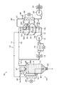
- FIG. 1 is a schematic explanatory view schematically showing a drying apparatus for granular material according to the first embodiment
- FIG. 2 is a control block diagram of the drying apparatus
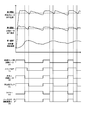
- FIG. 3 is a basic executed by the drying apparatus. It is a time chart for demonstrating an example of operation
- the drying apparatus 1 for the granular material shown in FIG. 1 generally includes a drying hopper unit 20, a dehumidifying unit 30, a processing gas circulation path 10 connecting the drying hopper unit 20 and the dehumidifying unit 30, and the same drying And a control unit 40 (see FIG. 2) provided at an appropriate position of the apparatus 1.
- the processing gas circulation path 10 passes through the processing gas supply path 11 for supplying the processing gas dehumidified by the dehumidifying unit 30 described later toward the drying hopper unit 20 described later, and the drying hopper unit 20.
- the process gas return path 12 used for the dehumidifying and drying process described later, which feeds the moisture-containing process gas toward the dehumidifying unit 30, and the process gas return path 12 are branched.
- a dehumidifying side branch pipe 12a and a regeneration side branch pipe 12b, and a regeneration cooling gas return path 16 for joining the regeneration cooling gas that has passed through a cooling regeneration zone 32c described later to the processing gas return path 12 are provided.
- the first temperature detection sensor 44, the circulation filter 13, the cooler 14, and the main blower 15 are arranged in this order from the drying hopper unit 20 to the dehumidifying unit 30.
- the first temperature detection sensor 44 is disposed in the vicinity of the exhaust port 25 of the hopper body 21 to be described later.
- the temperature of the processing gas that has passed through the body material layer is detected. As will be described later, this temperature is a temperature indicating the drying treatment state of the granular material m in the hopper body 21.
- the drying hopper unit 20 has a conical lower portion and a cylindrical upper portion, and is supplied through a hopper body 21 that stores the granular material materials m sequentially added from above and a dehumidifying unit 30 described later. And a heater 26 for heating the processing gas. Above the hopper body 21, there is a collector 27 for collecting and temporarily storing the particulate material m transported from a material tank (not shown) or the like via a material transport pipe 28. The material material valve m which is connected and provided below the collector 27 is opened, whereby the granular material m is sequentially introduced into the hopper body 21.
- the granular material m sequentially charged and stored in the hopper body 21 is subjected to dehumidification drying processing as will be described later, and the material discharge valve 23 provided below the hopper body 21 is opened. It is discharged sequentially toward the processing step (resin molding machine, temporary storage hopper, processing machine, etc. (not shown)).
- the above-mentioned injection of the granular material m into the hopper body 21 is performed based on, for example, a signal from a material sensor (not shown) such as a level gauge disposed in the upper part of the hopper body 21 to discharge the material.
- a material sensor such as a level gauge disposed in the upper part of the hopper body 21 to discharge the material.
- the valve 23 it is sequentially introduced and controlled so that the storage amount of the granular material m in the hopper body 21 is substantially constant. That is, the granular material m stored in a stacked state in the hopper body 21 is subjected to dehumidification drying treatment, and sequentially discharged from the lowest layer, and new granular material m is discharged. Depending on the amount, it is introduced from the upper collector 27.
- the powder material m refers to a powder / granular material, but includes a material such as a fine flake, short fiber, and sliver.
- materials which require dehumidification drying processing such as resin pellets, resin fiber pieces, etc., such as a synthetic resin material, or a metal material, a semiconductor material, a wood material, a chemical material, a food material, are included.
- the charging and discharging of the particulate material m as described above may be performed continuously or intermittently so that the storage amount in the hopper body 21 becomes a certain storage amount.
- the processing gas fed through the processing gas supply path 11 passes through the heater 26 and is heated and discharged from a discharge port 24 provided in the lower part of the hopper body 21. It is supplied into the main body 21.
- a second temperature detection sensor 45 for detecting the temperature of the processing gas that has passed through the heater 26 is disposed on the outlet side of the heater 26. Based on the temperature detected by the second temperature detection sensor 45, the CPU 41, which will be described later, controls energization such as ON / OFF control of the heater 26 or PID control.
- the temperature of the heated processing gas heated by the heater 26 and introduced into the hopper body 21 depends on the type and initial moisture content of the granular material m, the capacity of the hopper body 21 and the discharge amount. Although it can be set as appropriate, it may be about 80 ° C. to 160 ° C.
- the discharge port 24 is disposed at the approximate center of the hopper main body 21 formed in a circular shape in plan view, and the gas supplied through the processing gas supply path 11 is uniformly distributed and supplied. It is supposed to be configured.
- the processing gas discharged from the discharge port 24 passes upward between the granular material m stored in the hopper body 21, dehumidifies and drys the granular material m, and the hopper body 21.
- the air is supplied toward the exhaust port 25 formed at the upper portion of the gas, and is exhausted from the exhaust port 25 toward the processing gas return path 12.
- the dehumidifying unit 30 is a honeycomb-type dehumidifying unit that includes a honeycomb rotor (dehumidifying rotor) 31 that includes an adsorbent and constitutes an adsorbent, and lid bodies 32 that are disposed at both upper and lower ends thereof.
- the honeycomb rotor 31 is a cylindrical body having a large number of gas flow passages along the axial direction by impregnating a ceramic fiber formed in a honeycomb shape with an adsorbent, and is rotated by a rotation drive motor 39 (see FIG. 2).
- the shaft 33 is rotatable in the clockwise direction in the figure (in the direction of the white arrow).
- the honeycomb rotor 31 is rotated at a low speed and continuously, for example, at a rotational speed of about several to several tens of revolutions per hour.
- the adsorbent used in the honeycomb rotor 31 include silica gel, titanium silica gel, lithium chloride, and synthetic zeolite (trade name Molecular Sieve).
- the solid adsorbent is a heating gas for regeneration that can adsorb moisture and is described later. Any material can be used as long as it can be regenerated (moisture desorption) through the passage of water.
- the lid bodies 32 disposed at the upper and lower ends of the honeycomb rotor 31 are provided with inlets through which the gas from each path is introduced and outlets through which the gas is led out to each path.
- the lid 32 is formed with a partition wall 32d that constitutes a partition forming means for partitioning the dehumidification treatment zone 32a, the heating regeneration zone 32b, and the cooling regeneration zone 32c.
- Three partition walls 32d are provided in the centrifugal direction around the rotation shaft 33 of the honeycomb rotor 31, and in this embodiment, the volumes of the dehumidification treatment zone 32a, the heating regeneration zone 32b, and the cooling regeneration zone 32c are provided.
- the ratio is 5: 2: 1.
- the lid body 32 is fixed to the apparatus main body, and the honeycomb rotor 31 is rotated with respect to the lid body 32, so that the honeycomb rotor 31 is separated by the three partition walls 32d formed on the lid body 32. It is set as the structure divided into the said three divisions (zone) made into the airtight state mutually.
- the lid body 32 has a pair of upper and lower lower lid bodies 32 shown in the figure corresponding to the three partition walls 32d formed on the upper lid body 32, and the same three partition walls 32d are formed. Yes.
- Detailed description of the specific configuration of the honeycomb type dehumidifying unit as described above is omitted, but for example, Japanese Utility Model Laid-Open No. 60-115526, Japanese Utility Model Laid-Open No. 1-167318, Japanese Utility Model Laid-Open No. 2-13994. May be applied to the present embodiment.
- the dehumidifying side branch pipe 12a of the processing gas return path 12 is connected to the upstream side of the dehumidifying treatment zone 32a (lower cover body 32 in the figure), and the downstream side of the dehumidifying treatment zone 32a (upper cover body in the figure). 32) is connected to the processing gas supply path 11.
- the regeneration side branch pipe 12b of the processing gas return path 12 is connected to the upstream side of the cooling regeneration zone 32c (the lower cover body 32 in the figure), and the downstream side (the upper cover body in the figure) of the cooling regeneration zone 32c. 32) is connected to the regeneration cooling gas return path 16.
- a heating gas path 37 for regeneration which will be described later, is connected to the upstream side of the heating regeneration zone 32b (the upper lid body 32 in the figure), and downstream of the heating regeneration zone 32b (the lower lid body 32 in the figure).
- the discharge pipe 38 is connected.
- an intake filter 34, a regeneration blower 35, a regeneration heater 36, and a third temperature detection sensor 46 are arranged in this order from the upstream side toward the honeycomb rotor 31. .
- the regeneration heating gas path 37 by driving the regeneration blower 35, outside air is introduced through the intake filter 34 and heated by the regeneration heater 36 to generate regeneration heating gas.
- the heating gas for regeneration is introduced into the heating regeneration zone 32b of the honeycomb rotor 31, and is discharged from the discharge pipe 38 on the downstream side to the outside of the apparatus.
- the third temperature detection sensor 46 detects the temperature of the gas that has passed through the regeneration heater 36.
- the CPU 41 controls energization such as ON / OFF control of the regeneration heater 36 or PID control.
- the temperature of the regeneration heating gas introduced by being heated by the regeneration heater 36 may be about 180 ° C. to 240 ° C. in order to desorb moisture from the adsorbent that has adsorbed moisture.
- the dehumidifying process of the processing gas and the regeneration process of the honeycomb rotor 31 are performed as follows.
- the processing gas containing moisture by passing through the hopper body 21 in which the granular material m is stored is supplied to the main blower 15 disposed in the middle of the processing gas return path 12. By being driven, it is cooled through the circulation filter 13 and the cooler 14, and is introduced through the dehumidifying side branch pipe 12a.
- the processing gas introduced into the dehumidification processing zone 32a passes through the gas flow path in which the adsorbent in the honeycomb rotor 31 located there is disposed, moisture is adsorbed by the adsorbent, and as the dehumidified processing gas, Air is supplied toward the processing gas supply path 11 (dehumidification processing step).
- the adsorbent in the honeycomb rotor 31 that has adsorbed moisture in the dehumidifying zone 32 a reaches the heating regeneration zone 32 b as the honeycomb rotor 31 rotates.
- the regeneration heating gas is introduced through the regeneration heating gas path 37, the adsorbent that has adsorbed moisture is dried by heating, and regeneration of the adsorbent (desorption of moisture) is performed (heating). Regeneration process).
- the regeneration heating gas that has passed through the gas flow path in which the adsorbent in the honeycomb rotor 31 located in the heating regeneration zone 32b is disposed through the regeneration heating gas path 37 is exhausted to the outside of the apparatus via the discharge pipe 38. .
- the processing gas fed through the processing gas return path 12 is cooled through the cooler 14, and the cooled gas is introduced through the regeneration side branch pipe 12b for heating regeneration.
- the adsorbent that has been cooled is regenerated (cooling regeneration process). In this way, the processing gas is cooled for the purpose of protecting the main blower 15 and the adsorbent such as the synthetic zeolite has a characteristic that the moisture adsorption amount increases as the temperature becomes lower.
- the cooler 14 is preferably disposed on the upstream side of the main blower 15.
- the temperature of the processing gas cooled by the cooler 14 may be about 50 ° C. to 70 ° C.
- a known cooler such as a water-cooled type or an air-cooled type can be applied.
- the regeneration cooling gas that has passed through the regeneration-side branch pipe 12 b and passed through the gas flow passage in which the adsorbent in the honeycomb rotor 31 located in the cooling regeneration zone 32 c is disposed is the regeneration cooling gas downstream of the honeycomb rotor 31.
- the air is sent toward the return path 16, merged with the processing gas return path 12, and sent toward the dehumidifying unit 30.
- the adsorbent in the honeycomb rotor 31 that has been cooled and regenerated through the cooling and regenerating process reaches the dehumidifying treatment zone 32a as the honeycomb rotor 31 rotates.
- the dehumidifying process and heating regenerating process are performed.
- a cooling regeneration process is performed.
- the processing gas is configured to circulate between the drying hopper unit 20 and the dehumidifying unit 30.
- the processing gas dehumidified by the honeycomb rotor 31 of the dehumidifying unit 30 is supplied to the hopper body 21 to dehumidify and dry the granular material m.
- the heater can be downsized (lower power consumption), and the drying time can be shortened.
- the dew point of the outside air is high depending on the season, and it takes a long drying time to dry the granular material in the hopper body.
- a heater is required, according to the present embodiment, by supplying the processing gas that has been dehumidified by the honeycomb rotor 31 and has a low dew point into the hopper body 21, it is possible to efficiently produce a granular material.
- the material m can be dehumidified and dried.
- a processing gas having a stable dew point can be supplied into the hopper body 21.
- air is applied as a gas to be dehumidified and dried.
- a moisture-containing gas such as nitrogen, hydrogen, or argon is dehumidified and dried to the drying hopper. It may be introduced and the powder material m may be dehumidified and dried.
- the temperature and dew point of each gas sent through each of the above paths are the type and initial moisture of the granular material m to be dehumidified and dried, the capacity of the hopper body 21, the output of each heater and each blower, the honeycomb It is set as appropriate according to the shape of the rotor 31 and the like.
- the dew point of the dehumidified processing gas is, for example, about ⁇ 10 ° C. to ⁇ 60 ° C., preferably ⁇ 40 ° C. It may be set to from -50 ° C to -50 ° C.
- the control unit 40 constitutes a CPU 41 that controls each unit of the drying apparatus 1, and an operation unit that is operated to set various settings, set temperatures that will be described later, threshold values, and the like.
- An operation panel 42, a storage unit 43 that stores setting conditions set by operating the operation panel 42, a control program for executing a basic operation described later, and the like are provided.
- the CPU 41 is also connected to the above-described heater 26, main blower 15, regeneration heater 36, regeneration blower 35, rotation drive motor 39, first temperature detection sensor 44, and second temperature detection via a signal line.
- a sensor 45 and a third temperature detection sensor 46 are connected.
- the CPU 41 Based on the temperature detection signals of the first temperature detection sensor 44, the second temperature detection sensor 45, and the third temperature detection sensor 46, the CPU 41, as will be described later, the heater 26, the main blower 15, and the regeneration heater 36. The stop and start of the regeneration blower 35 and the rotary drive motor 39 are controlled.
- the horizontal axis is a time axis
- the temperature detected by each of the temperature detection sensors is indicated by the vertical axis.
- the heater 26 has a processing gas temperature (heater outlet temperature) that has passed through the heater 26 based on a temperature detection signal of the second temperature detection sensor 45 of 100 ° C. (heating The mode controlled by CPU41 so that it may become heater setting temperature) is shown.
- the regeneration heater 36 has a regeneration heater gas temperature (regeneration heater outlet temperature) 230 that has passed through the regeneration heater 36 based on the temperature detection signal of the third temperature detection sensor 46.
- the aspect controlled by CPU41 so that it may become (degreeC (regenerative heater preset temperature)) is shown. Further, in FIG. 3 and FIG. 5 to be described later, a state in which the granular material m is not charged into the hopper body 21 is shown. When the powder material m is charged, the material layer passing temperature ( The detected temperature of the first temperature detection sensor 44 is rapidly decreased, but the basic operation is the same.
- the CPU 41 detects the temperature of the processing gas that has passed through the granular material layer stored in the hopper body 21 (material layer passing temperature) from the first temperature detection sensor 44. Based on this temperature detection signal, the driving of the heater 26, the regeneration heater 36, and the rotary drive motor 39 of the honeycomb rotor 31 is stopped. That is, when the material layer passing temperature exceeds the first threshold value, the driving of the heater 26, the regeneration heater 36, and the rotary drive motor 39 of the honeycomb rotor 31 is stopped.
- the first threshold value can be set as appropriate according to the capacity and discharge amount of the hopper body 21 and the type and conditions (such as initial moisture content) of the granular material m to be dehumidified and dried. It is about 50 ° C.
- Such a first threshold is a state in which at least the granular material m to be discharged in the lower layer portion is sufficiently dehumidified and dried according to the discharged amount of the granular material stacked in the hopper body 21. It is set experimentally or experimentally.
- the timer of the CPU 41 is turned on and a predetermined first time is counted.
- This first time can be set as appropriate according to the capacity and discharge amount of the hopper body 21 and the type and conditions (such as initial moisture content) of the granular material m to be dehumidified and dried.
- the heater outlet temperature and the regeneration heater outlet temperature are longer than the time required for each to decrease to a predetermined temperature, and the temperature of the granular material m stored in the hopper body 21 is It is preferable to set the time so as not to decrease extremely.
- the drive of the main blower 15 is stopped based on a temperature detection signal from the second temperature detection sensor 45 that detects the temperature that passes through the heater 26 (heater outlet temperature). That is, when the heater outlet temperature at which the set temperature is 100 ° C. as described above falls below 90 ° C. (second threshold), the main blower 15 is stopped.
- the second threshold value can be set as appropriate according to the heater setting temperature, the output of the heater 26 and the main blower 15, the supply air volume, and the like. Since a low-temperature gas extremely lower than the set temperature is blown, the heater outlet temperature detected by the air blown by the inertia moment (inertia) of the main blower 15 immediately after the main blower 15 is stopped is 10 ° C. above the set temperature.
- the driving of the regeneration blower 35 is stopped based on a temperature detection signal from the third temperature detection sensor 46 that detects the temperature passing through the regeneration heater 36 (regeneration heater outlet temperature). That is, when the regeneration heater outlet temperature at which the set temperature is set to 230 ° C. as described above falls below 200 ° C. (third threshold value), the regeneration blower 35 is stopped.
- the third threshold value can be appropriately set according to the regeneration heater set temperature, the output of the regeneration heater 36 and the regeneration blower 35, etc., but the regeneration threshold immediately after the regeneration blower 35 is stopped.
- the regeneration heater outlet temperature detected by the air blown by the moment of inertia (inertia) of the blower 35 becomes a temperature that does not damage the terminals of the regeneration heater 36 or the like.
- the third threshold value is not set extremely low. It is preferable. Thereby, when it restarts, the temperature rise for the heating reproduction
- the main blower 15 and the regeneration blower 35 are stopped according to the predetermined condition.
- the heater 26, main blower 15, regeneration heater 36, regeneration blower 35, and rotary drive motor 39 of the honeycomb rotor 31 are restarted. Is done. At this time, it is preferable to restart them substantially simultaneously. Thereby, the bad influence to the granular material material m in the hopper main body 21, and the bad influence to the regeneration process of the honeycomb rotor 31, etc. can be reduced.
- the heater 26, the regeneration heater 36, and the rotary drive motor 39 of the honeycomb rotor 31 are stopped, and further, the heater outlet temperature is When the temperature falls below the second threshold, the main blower 15 is stopped.
- the regeneration heater outlet temperature falls below the third threshold, the regeneration blower 35 is stopped, and then the heater 26,
- the rotation drive motor 39 is restarted.
- FIG. 3 shows a state in which a new powder material m is not charged into the hopper body 21, for example, a preparatory operation state such as when the drying apparatus 1 is started.
- the granular material material m containing water at room temperature is charged and stored until a predetermined storage amount is reached.
- This storage amount is controlled by a level gauge provided in the upper part of the hopper body 21 described above, and during this preparatory operation period, the powder material m is not discharged and charged, and the lower layer portion in the hopper body 21
- the powder material m is dehumidified and dried until it reaches a predetermined temperature and moisture content.
- the operation time of this preparation operation is appropriately set according to the capacity of the hopper body 21, the type and conditions of the granular material m, the amount of the granular material m to be discharged sequentially, and the like. That is, the granular material m stored in the hopper body 21 is gradually heated from the granular material m located in the lowermost layer by the processing gas discharged from the lower discharge port 24 in the hopper body 21. Dehumidification is performed, and the operation is continued so that the temperature of about 50% to 70% of the granular material m from the lowermost part of the granular material m stored in the hopper body 21 becomes a predetermined temperature.
- the dehumidifying and drying of the predetermined amount of the granular material material m discharged from the lowermost layer is sequentially sufficiently performed during the continuous operation, and the predetermined moisture content is Preparatory operation is continued until
- a predetermined amount of the granular material m is supplied to the resin molding machine and the primary storage hopper.
- the operation is shifted to a continuous operation in which the particulate material m is charged from the collector 27 according to the discharged amount.
- the discharge and input of the granular material m are periodically repeated based on, for example, a material request signal from a resin molding machine or a primary storage hopper.
- the material layer passing temperature is rapidly lowered by the newly introduced granular material m according to the discharge amount of the granular material m.
- the powder material m from the lowermost part of the hopper body 21 is sufficiently heated during the preparation operation to reach a predetermined temperature, but the powder newly introduced into the upper layer part.
- the body material m is not yet sufficiently heated, and, for example, has a low temperature of about room temperature, so that the material layer passing temperature is lowered.
- the heater 26, the regeneration heater 36, and the rotary drive motor 39 of the honeycomb rotor 31 are not stopped, and the inside of the hopper main body 21 is not stopped.
- Dehumidification drying processing of the granular material m, dehumidification processing of the processing gas in the honeycomb rotor 31, heating regeneration and cooling regeneration of the adsorbent are performed.
- the material layer passing temperature is For example, when the powder material m is deteriorated (oxidation, burn, decomposition, discoloration, etc.) or an additive is added to the powder material m, the additive May scatter. Moreover, there is a possibility that the load on the cooler 14 disposed in the processing gas return path 12 may increase due to the useless increase in the material layer passing temperature.
- the heater 26 and the main blower 15 may be stopped, and the regeneration heater 36, the regeneration blower 35, and the rotational drive motor 39 of the honeycomb rotor 31 may continue to operate.
- the heater 26, the main blower 15, the regeneration heater 36, and the regeneration blower 35 may be stopped, and the rotational drive motor 39 of the honeycomb rotor 31 may continue to operate.
- a honeycomb type is used as the dehumidifying unit, and the adsorbent is a single honeycomb rotor 31.
- the present invention is not limited to this.
- the dehumidifying unit is a multi-tower type having a plurality of adsorption towers. It is good also as a thing.
- each path and each adsorption tower is switched by a switching valve, or each adsorption tower is rotated with respect to each path so that each path and each adsorption tower are switched.
- the processing gas circulation path as in this embodiment is provided, the processing gas is dehumidified and supplied, and the adsorbent is regenerated. It is.
- Such multi-column type dehumidifying units are disclosed in, for example, Japanese Patent Application Laid-Open Nos. 60-178809 and 60-132622.
- the adsorbent disposed corresponding to each of the dehumidification treatment zone, the heating regeneration zone, and the cooling regeneration zone is constituted by one honeycomb rotor 31, and the partition wall 32 d is accompanied by the rotation of the honeycomb rotor. Is moved relative to the honeycomb rotor 31 so that each zone sequentially moves, a dehumidification treatment step for dehumidifying the processing gas, a heating regeneration step for heating and regenerating a part of the honeycomb rotor, and a part of the honeycomb rotor.
- the cooling regeneration process for cooling and regenerating is performed in parallel.
- each path and each adsorption tower switching between each path and each adsorption tower is performed by a switching valve, or by rotating each adsorption tower with respect to each path,
- each of the zones is sequentially configured, and a dehumidification treatment process for dehumidifying the processing gas, a heating regeneration process for heating and regenerating the adsorption tower, and a cooling regeneration process for cooling and regenerating the adsorption tower are performed.
- the multi-column type dehumidifying unit is inferior in terms of dew point uniformity compared to the honeycomb type dehumidifying unit applied in the present embodiment. An effect is obtained.
- the timer for counting the first time is started and then increased. Until that time, the timer for switching may be temporarily stopped. According to this, it is possible to prevent switching without being sufficiently reproduced.
- the dehumidifying unit may include a plurality of honeycomb rotors.
- a plurality of honeycomb rotors may be arranged in parallel with respect to each path.
- the present invention can be applied by branching each path to each zone of the plurality of honeycomb rotors.
- the drying device may include a plurality of dehumidifying units.
- a plurality of dehumidifying units may be arranged in parallel to the drying hopper unit.
- the processing gas return path 12 is branched and connected to the honeycomb rotor of each dehumidification unit
- the processing gas supply path 11 is branched and connected to the honeycomb rotor of each dehumidification unit.
- the present invention can be applied.
- FIG. 4 is a schematic explanatory view schematically showing a drying apparatus for granular material according to the second embodiment
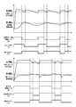
- FIG. 5 is a time chart for explaining an example of a basic operation executed by the drying apparatus.
- Note that differences from the first embodiment will be mainly described, and the same components are denoted by the same reference numerals, and description thereof will be omitted or simplified. Also, description of similar basic operations will be omitted or briefly described.
- the internal structure of the drying apparatus of the granular material according to the present embodiment is substantially the same as the first embodiment described with reference to FIG. Omitted or briefly described.
- the powder material drying apparatus 1A is provided with a first temperature detection sensor 44A for detecting the material layer passing temperature of the processing gas that has passed through the powder material layer in the hopper body 21.
- the first temperature detection sensor 44A has a granular material in a state where the granular material m stored in the hopper body 21 is stored to a full level as shown in FIG.
- the detection part is arranged to face the space from the uppermost layer part of the material m to the canopy that closes the upper end part of the hopper body 21.
- the first temperature detection sensor 44A measures the ambient temperature of the space (hereinafter abbreviated as material non-reserved space) sp above the granular material layer stored in the hopper body 21.
- the temperature of the material non-reserving space sp in the hopper body 21 changes in substantially the same manner as the change in the material layer passage temperature described in the first embodiment.
- the first temperature detection sensor 44A the temperature indicating the drying treatment state of the granular material m in the hopper body 21 is detected.
- the powder material drying apparatus 1A in order to detect the temperature (heating heating zone passage temperature) of the regeneration heating gas that has passed through the honeycomb rotor 31 in the heating regeneration zone 32b of the dehumidifying unit 30, the powder material drying apparatus 1A according to the present embodiment is used.
- the fourth temperature detection sensor 47 is provided in the discharge pipe 38. As shown in FIG. 2, the fourth temperature detection sensor 47 is connected to the CPU 41 by a signal line. Based on the temperature detection signal of the fourth temperature detection sensor 47, the CPU 41, as will be described later, The stop and start of the regeneration heater 36 are controlled.
- the stop of the heater 26 is not linked with the stop of the regeneration heater 36 and the rotary drive motor 39 of the honeycomb rotor 31 in the basic operation described in the first embodiment.
- the CPU 41 performs heating when the material layer passing temperature exceeds the first threshold based on the temperature detection signal from the first temperature detection sensor 44A that detects the material layer passing temperature.
- the heater 26 is stopped, and the main blower 15 is stopped when the heater outlet temperature in the stopped state is lower than the second threshold, as described above.
- the first timer of the CPU 41 is turned on, the predetermined first time is counted, and when the first timer is up, the heater 26 and the main blower 15 are turned off. Reboot.
- the CPU 41 stops the regeneration heater 36 when the heating regeneration zone passage temperature exceeds the fourth threshold value, and further regenerates in the halted state as described above.
- the heater outlet temperature for the heater falls below the third threshold value, the regeneration blower 35 is stopped.
- the fourth threshold value can be appropriately set according to the shape and rotational speed (angular speed) of the honeycomb rotor 31, the output of the regeneration heater 36 and regeneration blower 35, the regeneration heater setting temperature described above, and the like. However, in this example, the temperature is about 100 ° C.
- Such a fourth threshold value is set empirically or experimentally so that moisture is sufficiently desorbed from the adsorbent in the heating regeneration zone 32b and the adsorbent is sufficiently heated and regenerated.
- the regeneration heater 36 when the regeneration heater 36 is stopped, the second timer of the CPU 41 is turned on, a predetermined second time is counted, and when the second timer is increased, the regeneration heater 36 and the regeneration heater 36 are regenerated.
- the blower 35 is restarted.
- This second time can be set as appropriate according to the shape and rotation speed (angular speed) of the honeycomb rotor 31, the output of the regeneration heater 36 and regeneration blower 35, the regeneration heater set temperature described above, and the like. However, if it is too long, the amount of adsorption by the adsorbent may be reduced as the treatment gas is dehumidified in the dehumidification treatment zone 32a of the honeycomb rotor 31 that is continuously rotated.
- the regeneration heater 36 is stopped. Since the regeneration blower 35 is stopped when the temperature of the gas passing through the heater 36 falls below a predetermined temperature, energy saving can be achieved. That is, it is possible to determine the heating regeneration process state of the honeycomb rotor 31 based on the temperature of the gas that has passed through the heating regeneration zone 32b of the honeycomb rotor 31, and to stop the regeneration heater 36 and regeneration blower 35. Energy saving can be achieved.
- the rotation drive motor 39 of the honeycomb rotor 31 is illustrated as being operated without stopping even when the heaters 26 and 36 are stopped.
- the heaters 26 and 36 may be stopped in conjunction with the stop.
- the rotation drive motor 39 of the honeycomb rotor 31 may be stopped.
- the adsorbent in the heating regeneration zone 32b is also stopped, and after the heating regeneration is performed, the regeneration heater 36 and the like are stopped as described above, so that energy saving can be achieved.
- the rotational speed of the honeycomb rotor 31 is relatively low, and, for example, in summer, the dew point of the outside air is high, so the heating regeneration zone passage temperature is less frequently than the fourth threshold value, and the regeneration Since the heater 36 and the regeneration blower 35 are stopped less frequently, the heating and regeneration of the honeycomb rotor 31 is not so hindered. Therefore, it is possible to continue the rotation as described above. In winter and the like, since the dew point of the outside air is low, even when the regeneration heater 36 and regeneration blower 35 are stopped, the heat regeneration of the honeycomb rotor 31 is not so hindered. Further, it is possible to continue the rotation as described above.
- a multi-column dehumidification unit as described above, or a plurality of honeycomb rotors, a plurality of A dehumidifying unit or the like may be applied.
- the switching may be performed regardless of whether the heaters 26 and 36 are stopped.
- the second time is preferably set shorter than the switching timing.
- the timer for switching is temporarily set until the timer for counting the first time is started up and then up. You may make it stop.
- the regeneration heater 36 and the regeneration blower 35 are stopped as described above, so that energy saving can be achieved.
- FIG. 6 (a) schematically shows a part of the drying apparatus for granular material according to the third embodiment
- FIG. 6 (b) shows the drying apparatus for granular material according to the fourth embodiment.
- a part is schematically shown. Note that the difference from the first embodiment and the second embodiment will be mainly described, and the same components are denoted by the same reference numerals, and description thereof will be omitted or simplified. Also, description of similar basic operations will be omitted or briefly described.
- 6A and 6B the dehumidifying unit is not shown, but each dehumidifying unit described in each of the above embodiments can be applied.
- each drying apparatus of each granular material which concerns on the following 3rd Embodiment and 4th Embodiment is each drying apparatus which concerns on the said 1st Embodiment and 2nd Embodiment which were demonstrated based on FIG.
- the reference numerals are attached to FIG. 2 and the description thereof is omitted.
- the granular material drying apparatus 1B according to the third embodiment shown in FIG. 6A is different from the granular material drying apparatuses 1 and 1A according to the first and second embodiments described above.
- the location of the temperature detection sensor is different. That is, in this embodiment, it replaces with the said 1st temperature detection sensors 44 and 44A, The 1st temperature detection sensor for detecting the temperature in the upper layer part of the granular material m stored in the hopper main body 21 48 (see also FIG. 2).
- the first temperature detection sensor 48 is disposed such that its detection portion is positioned slightly below the hopper body 21 than the first temperature detection sensor 44A described in the second embodiment. That is, as shown in FIG. 6A, the first temperature detection sensor 48 has a detection unit in the upper part of the granular material layer stored in the hopper body 21. It is arranged so as to be positioned, and the temperature inside the granular material layer of the upper layer portion, that is, the temperature of the granular material npm in the granular material layer is substantially measured. .
- the powder material npm in the upper layer is collected according to the discharge amount of the powder material m discharged by opening the material discharge valve 23 in the lower part of the hopper body 21 during the above-described continuous operation.
- This is a granular material newly introduced from the container 27.
- the storage level of the granular material m of the hopper body 21 is lowered by the discharge from the lower part, and the material charging start level at which the material charging from the collector 27 is started. From this position, the granular material is newly charged and stored until it reaches a predetermined full level.
- the powder material npm newly input as described above is, for example, about room temperature immediately after being input, and is gradually heated by the processing gas supplied into the hopper body 21.
- the temperature of the particulate material npm changes in substantially the same manner as the change in the material layer passing temperature described in the first and second embodiments.
- the temperature of the powder material npm is changed by the first temperature detection sensor 48.
- the temperature which shows the dry processing state of the granular material material m in the hopper main body 21 is detected. That is, the temperature of the powder material npm gradually increases as the dehumidifying and drying process by the supply of the processing gas proceeds from a temperature of about room temperature immediately after being charged.
- the temperature of the particulate material npm is measured by the first temperature detection sensor 48, and the heater 26 and the like are stopped based on the temperature detection signal as described above.
- the basic operation similar to that of the first embodiment or the second embodiment can be applied to the basic operation in the drying apparatus 1B for the granular material, that is, the mode of stopping and starting each device.
- the granular material drying apparatus 1C according to the fourth embodiment shown in FIG. 6B is different from the granular material drying apparatus 1B according to the third embodiment in the arrangement of the first temperature detection sensor 48A.
- the place is different.
- the first temperature detection sensor 48A has a lower detection position in the hopper body 21 than the first temperature detection sensor 48 described in the third embodiment. They are arranged as follows.
- the first temperature detection sensor 48A is disposed so that the detection part is located in the granular material layer that is in the temperature rising process during the above-described continuous operation, and the rising temperature stored in the upper layer part is disposed.
- the temperature inside the granular material layer in the temperature process that is, substantially the temperature of the granular material nhm in the granular material layer is measured.
- the particulate material nhm in the temperature raising process is a particulate material that has not yet been sufficiently heated during the above-described preparation operation and continuous operation, and is sufficiently heated during the preparation operation.
- it is a granular material having a temperature lower than that of the lower granular material hm that has reached a predetermined temperature. That is, the powder material hm in the lower layer is heated to a predetermined temperature before shifting to the continuous operation as described in the first embodiment, but is stored in the upper layer.
- the granular material nhm is in a state where the temperature has not been raised to the predetermined temperature during the preparation operation and the continuous operation.
- the temperature distribution of the granular material stored in the hopper body 21 is substantially constant in the lower layer part, and gradually increases toward the uppermost layer part on the upper layer side of the lower layer part.
- the distribution is so low.
- almost all of the granular material hm stored in the lower layer reaches a constant temperature at the end of the preparation operation and during the continuous operation.
- the granular material material nhm stored on the upper layer side of the lower granular material material hm and the newly introduced granular material material npm are in a temperature rising process and reach the predetermined temperature. They are laminated so that the temperature gradually decreases toward the uppermost layer.
- the temperature of the particulate material nhm in the temperature rising process changes in a higher temperature range than the above embodiments, but changes so as to repeatedly descend and rise as the particulate material is discharged and charged. To do. That is, in the hopper main body 21 having the temperature distribution as described above, the first temperature detection sensor 48A detects the discharge of a part of the lower layer powder material hm from the lower portion of the hopper main body 21. Around the part, among the granular material nhm in the temperature rising process, the lower temperature granular material falls. The lowered granular material nhm is gradually heated by the processing gas supplied from the discharge port 24, and the temperature gradually increases, as in the above embodiments.
- the temperature of the particulate material nhm in the temperature rising process is detected by the first temperature detection sensor 48A as a temperature indicating the drying processing state of the particulate material m in the hopper body 21. Yes.
- the heater 26 and the like are stopped based on the temperature detection signal.
- the basic operation similar to that of the first embodiment or the second embodiment can be applied to the basic operation of the powder material drying apparatus 1C, that is, the mode of stopping and starting each device.
- the first threshold value described in each of the above embodiments does not have a rapid temperature drop due to the newly introduced granular material as in each of the above embodiments, and the temperature rises to some extent. Since the temperature of the made granular material nhm is measured, it is set higher than each above-mentioned embodiment.
- the same effects as those of the drying apparatus 1 and 1A for the granular material according to the first embodiment or the second embodiment can be obtained.
- the drying treatment state of the granular material m in the hopper body 21 is determined based on the temperature of the granular material nhm in the temperature rising process, compared to the above embodiments.
- the vertical width of the temperature change to be detected is small, and more precise and precise control can be performed.
- the heater 26 and the like are stopped as described above based on the temperature of the powder material nhm before moving to the lower layer portion with the discharge from the lower part of the hopper body 21, the lower layer portion It is also possible to control so that the powder material hm has the predetermined temperature.
- the heater 26 and the like as described above By stopping this, it becomes possible to control the temperature distribution of the preferable granular material as described above in the hopper body 21.
- the amount of the granular material hm in the lower layer part and the amount of the granular material nhm in the temperature rising process are the discharge amount and discharge mode (discharge frequency, etc.) from the lower part of the hopper body 21. ) To be set as appropriate. That is, the lower layer granular material hm so that the predetermined amount of granular material discharged in the lowermost layer in response to the material request signal from the molding machine etc. is always sufficiently dehumidified and dried. And each amount of the particulate material nhm in the temperature raising process may be set.
- the first temperature detection sensors 44A, 48, and 48A disposed in the upper layer portions for detecting the temperature of the upper layer portion in the hopper body 21 are provided as the hopper body.
- the example provided inward from the side wall of 21 is shown, it is good also as an aspect provided inward from the canopy of the hopper main body 21.
- the aspect detects a material layer passage temperature.
- a first temperature detection sensor 44 for detecting the temperature exhausted from the first temperature detection sensor 44A (second embodiment) for detecting the temperature of the material non-reserving space sp in the hopper body 21), A mode for detecting the temperature in the upper layer part of the material layer (first temperature detection sensor 48 for detecting the temperature in the upper layer part of the granular material m stored in the hopper body 21 (third embodiment), The first temperature detection sensor 48A (fourth embodiment) that detects the temperature inside the granular material layer in the temperature rising process stored in the upper layer portion in the hopper body 21 is illustrated as an example. Granule material in 21 The detection of the temperature indicating the drying process conditions is possible, it may be disposed the first temperature sensor to the other site.
- each said embodiment illustrated the aspect which circulates and supplies the process gas dehumidified and dried by the said dehumidification unit 30 to the said hopper main body 21, it is not restricted to such an aspect.
- a drying apparatus 1 ⁇ / b> D including only the drying hopper unit 20 including a blower such as the control unit 40 and the main blower 15.
- any one of the first temperature detection sensors may be provided.
- the present invention can also be applied to a drying apparatus that does not include the dehumidifying unit 30. As described above, energy saving can be achieved, and adverse effects on the particulate material m in the hopper body 21 can be reduced.
- the dehumidification unit may be provided with a one-column type adsorption tower instead of the one that is performed in parallel with the regeneration of the adsorption tower.
- the heater may be stopped as described above based on the temperature detected by the first temperature detection sensor.
- a switching valve or the like may be switched to the regeneration side.
- the mode may be switched to the processing gas circulation path side. . Thereby, drying of the granular material in the hopper body and regeneration of the adsorption tower are efficiently performed.
Landscapes
- Engineering & Computer Science (AREA)
- Mechanical Engineering (AREA)
- Chemical & Material Sciences (AREA)
- General Engineering & Computer Science (AREA)
- Analytical Chemistry (AREA)
- General Chemical & Material Sciences (AREA)
- Oil, Petroleum & Natural Gas (AREA)
- Chemical Kinetics & Catalysis (AREA)
- Drying Of Solid Materials (AREA)
- Drying Of Gases (AREA)
Abstract
Le dispositif de séchage (1) de matériau de fines particules, qui comprend une trémie de séchage (21) stockant le matériau de fines particules, ainsi qu'une soufflante (15) et un appareil de chauffage (26) permettant d'alimenter ladite trémie de séchage en gaz chauffé, est équipé d'un premier capteur de détection de température (44), qui détecte la température indiquant l'état du traitement de séchage du matériau de fines particules à l'intérieur de ladite trémie de séchage; d'un second capteur de détection de température (45) qui détecte la température du gaz traversant l'appareil de chauffage susmentionné; et d'un moyen de contrôle (41). Ce moyen de contrôle (41) arrête l'appareil de chauffage susmentionné lorsque la température détectée par le premier capteur de détection de température susmentionné excède le premier seuil préalablement déterminé; arrête la soufflante susmentionnée lorsque la température détectée par le second capteur de détection de température susmentionné excède, lors dudit état d'arrêt, le second seuil préalablement déterminé; et déclenche l'appareil de chauffage et la soufflante susmentionnés, lorsqu'une première période de temps prédéterminée s'est écoulée depuis l'arrêt de l'appareil de chauffage susmentionné.
Priority Applications (1)
| Application Number | Priority Date | Filing Date | Title |
|---|---|---|---|
| CN200980143908.5A CN102203534B (zh) | 2008-11-05 | 2009-11-04 | 粉粒体材料的干燥方法及粉粒体材料的干燥装置 |
Applications Claiming Priority (2)
| Application Number | Priority Date | Filing Date | Title |
|---|---|---|---|
| JP2008284390A JP5512114B2 (ja) | 2008-11-05 | 2008-11-05 | 粉粒体材料の乾燥方法、及び粉粒体材料の乾燥装置 |
| JP2008-284390 | 2008-11-05 |
Publications (1)
| Publication Number | Publication Date |
|---|---|
| WO2010053090A1 true WO2010053090A1 (fr) | 2010-05-14 |
Family
ID=42152898
Family Applications (1)
| Application Number | Title | Priority Date | Filing Date |
|---|---|---|---|
| PCT/JP2009/068828 Ceased WO2010053090A1 (fr) | 2008-11-05 | 2009-11-04 | Procédé de séchage de matériau de fines particules et dispositif de séchage de matériau de fines particules |
Country Status (3)
| Country | Link |
|---|---|
| JP (1) | JP5512114B2 (fr) |
| CN (1) | CN102203534B (fr) |
| WO (1) | WO2010053090A1 (fr) |
Cited By (4)
| Publication number | Priority date | Publication date | Assignee | Title |
|---|---|---|---|---|
| JP2019108992A (ja) * | 2017-12-15 | 2019-07-04 | 井関農機株式会社 | 穀物乾燥機 |
| US10782069B2 (en) | 2014-06-10 | 2020-09-22 | Ctb, Inc. | Equilibrium moisture grain drying with heater and variable speed fan |
| IT201900018854A1 (it) * | 2019-10-15 | 2021-04-15 | Pegaso Ind S P A | Processo di essiccamento di materiale granulare polimerico e impianto di essiccamento operante secondo tale processo |
| IT202300010956A1 (it) * | 2023-05-30 | 2024-11-30 | Piovan Spa | Apparato e metodo per processare materiale incoerente |
Families Citing this family (6)
| Publication number | Priority date | Publication date | Assignee | Title |
|---|---|---|---|---|
| JP5931002B2 (ja) * | 2013-04-19 | 2016-06-08 | エクアールシー株式会社 | 低湿庫用乾燥装置 |
| CN104824785A (zh) * | 2015-04-03 | 2015-08-12 | 安徽省农业科学院农产品加工研究所 | 一种粉粒体过热蒸汽连续灭菌装置及控制方法 |
| JP6644483B2 (ja) * | 2015-06-12 | 2020-02-12 | 株式会社カワタ | 加熱装置および加熱装置の制御方法 |
| JP2021076344A (ja) * | 2019-11-13 | 2021-05-20 | 株式会社カワタ | 粉粒体処理装置および粉粒体処理方法 |
| JP7530242B2 (ja) * | 2020-08-27 | 2024-08-07 | シャープ株式会社 | 吸湿装置 |
| JP7644960B2 (ja) * | 2021-02-05 | 2025-03-13 | 株式会社カワタ | 粉粒体処理装置および粉粒体処理方法 |
Citations (4)
| Publication number | Priority date | Publication date | Assignee | Title |
|---|---|---|---|---|
| JP2000320970A (ja) * | 1999-05-06 | 2000-11-24 | Satake Eng Co Ltd | 穀物乾燥機 |
| JP2005003287A (ja) * | 2003-06-12 | 2005-01-06 | Yamamoto Co Ltd | 燃焼器 |
| JP3914566B2 (ja) * | 1997-06-10 | 2007-05-16 | 株式会社松井製作所 | 粉粒体材料の除湿乾燥装置 |
| JP4020482B2 (ja) * | 1998-04-03 | 2007-12-12 | 株式会社カワタ | 乾燥装置 |
Family Cites Families (6)
| Publication number | Priority date | Publication date | Assignee | Title |
|---|---|---|---|---|
| JPS60178009A (ja) * | 1984-02-25 | 1985-09-12 | Color Toronitsuku Kk | 合成樹脂乾燥用の高温除湿空気発生方法およびその装置 |
| JP2858376B2 (ja) * | 1990-11-27 | 1999-02-17 | 松下電器産業株式会社 | 電気こんろ |
| JPH0576683A (ja) * | 1991-09-24 | 1993-03-30 | Sharp Corp | 全自動洗濯機 |
| JPH08271051A (ja) * | 1995-04-03 | 1996-10-18 | Suzuki Motor Corp | 送風式暖房器具 |
| JPH0994395A (ja) * | 1995-09-29 | 1997-04-08 | Toto Ltd | 浴室暖房衣類乾燥機 |
| JP2007204871A (ja) * | 2006-02-01 | 2007-08-16 | Tsudakoma Corp | 経糸糊付装置に用いられる熱風乾燥装置の温度制御方法。 |
-
2008
- 2008-11-05 JP JP2008284390A patent/JP5512114B2/ja active Active
-
2009
- 2009-11-04 CN CN200980143908.5A patent/CN102203534B/zh not_active Expired - Fee Related
- 2009-11-04 WO PCT/JP2009/068828 patent/WO2010053090A1/fr not_active Ceased
Patent Citations (4)
| Publication number | Priority date | Publication date | Assignee | Title |
|---|---|---|---|---|
| JP3914566B2 (ja) * | 1997-06-10 | 2007-05-16 | 株式会社松井製作所 | 粉粒体材料の除湿乾燥装置 |
| JP4020482B2 (ja) * | 1998-04-03 | 2007-12-12 | 株式会社カワタ | 乾燥装置 |
| JP2000320970A (ja) * | 1999-05-06 | 2000-11-24 | Satake Eng Co Ltd | 穀物乾燥機 |
| JP2005003287A (ja) * | 2003-06-12 | 2005-01-06 | Yamamoto Co Ltd | 燃焼器 |
Cited By (6)
| Publication number | Priority date | Publication date | Assignee | Title |
|---|---|---|---|---|
| US10782069B2 (en) | 2014-06-10 | 2020-09-22 | Ctb, Inc. | Equilibrium moisture grain drying with heater and variable speed fan |
| JP2019108992A (ja) * | 2017-12-15 | 2019-07-04 | 井関農機株式会社 | 穀物乾燥機 |
| JP7057544B2 (ja) | 2017-12-15 | 2022-04-20 | 井関農機株式会社 | 穀物乾燥機 |
| IT201900018854A1 (it) * | 2019-10-15 | 2021-04-15 | Pegaso Ind S P A | Processo di essiccamento di materiale granulare polimerico e impianto di essiccamento operante secondo tale processo |
| IT202300010956A1 (it) * | 2023-05-30 | 2024-11-30 | Piovan Spa | Apparato e metodo per processare materiale incoerente |
| EP4470742A1 (fr) * | 2023-05-30 | 2024-12-04 | Piovan S.P.A. | Appareil et procédé de traitement de matériau incohérent |
Also Published As
| Publication number | Publication date |
|---|---|
| JP2010112607A (ja) | 2010-05-20 |
| CN102203534B (zh) | 2014-08-13 |
| JP5512114B2 (ja) | 2014-06-04 |
| CN102203534A (zh) | 2011-09-28 |
Similar Documents
| Publication | Publication Date | Title |
|---|---|---|
| JP5512114B2 (ja) | 粉粒体材料の乾燥方法、及び粉粒体材料の乾燥装置 | |
| JP5211056B2 (ja) | 粉粒体材料の除湿乾燥方法、及び粉粒体材料の除湿乾燥システム | |
| JP3955109B2 (ja) | 湿ったガスを乾燥するための方法および装置 | |
| JP4546215B2 (ja) | 乾燥ホッパにおける粒状物を通過するガス流量制御方法及び装置 | |
| JP5401121B2 (ja) | 粉粒体材料の除湿乾燥装置 | |
| EP2585196A1 (fr) | Système et procédé d'amélioration de la performance d'un équipement de déshumidification dessicatif pour applications à faible humidité | |
| CN105202877B (zh) | 一种多桶分子筛转轮间歇循环式除湿干燥机 | |
| KR102439788B1 (ko) | 듀얼 제습로터를 구비한 제습장치 | |
| JPH1052622A (ja) | 湿気等を含んだ吸着剤を再生するための方法および装置 | |
| JP7280652B1 (ja) | 合成樹脂成形材料の除湿乾燥システム | |
| CN208012245U (zh) | 一种分度运动多桶式除湿装置 | |
| CN205037696U (zh) | 一种多桶分子筛转轮间歇循环式除湿干燥机 | |
| JP4020482B2 (ja) | 乾燥装置 | |
| CN205033413U (zh) | 多组多桶分子筛转轮交替间歇循环式除湿干燥机 | |
| CN105196440B (zh) | 多组多桶分子筛转轮交替间歇循环式除湿干燥机 | |
| TWI878844B (zh) | 合成樹脂成形材料的除濕乾燥系統 | |
| CN219563821U (zh) | 一种蜂巢式三机一体除湿干燥设备 | |
| CN219454462U (zh) | 粉粒体材料的干燥装置 | |
| CN219347064U (zh) | 粉粒体材料的干燥装置 | |
| JP5064117B2 (ja) | 粉粒体材料の除湿乾燥方法、及び粉粒体材料の除湿乾燥システム | |
| JP7425520B1 (ja) | 合成樹脂成形材料の乾燥装置 | |
| JP4075813B2 (ja) | 収納乾燥庫 | |
| CA3288260A1 (fr) | Système de séchage par déshumidification pour matériau de moulage en résine synthétique | |
| JP2021076344A (ja) | 粉粒体処理装置および粉粒体処理方法 | |
| JP2015038392A (ja) | 乾燥装置 |
Legal Events
| Date | Code | Title | Description |
|---|---|---|---|
| WWE | Wipo information: entry into national phase |
Ref document number: 200980143908.5 Country of ref document: CN |
|
| 121 | Ep: the epo has been informed by wipo that ep was designated in this application |
Ref document number: 09824789 Country of ref document: EP Kind code of ref document: A1 |
|
| NENP | Non-entry into the national phase |
Ref country code: DE |
|
| 122 | Ep: pct application non-entry in european phase |
Ref document number: 09824789 Country of ref document: EP Kind code of ref document: A1 |