WO2010055847A1 - ジャーナル軸受 - Google Patents
ジャーナル軸受 Download PDFInfo
- Publication number
- WO2010055847A1 WO2010055847A1 PCT/JP2009/069188 JP2009069188W WO2010055847A1 WO 2010055847 A1 WO2010055847 A1 WO 2010055847A1 JP 2009069188 W JP2009069188 W JP 2009069188W WO 2010055847 A1 WO2010055847 A1 WO 2010055847A1
- Authority
- WO
- WIPO (PCT)
- Prior art keywords
- bearing
- journal
- oil supply
- load
- bearing housing
- Prior art date
- Legal status (The legal status is an assumption and is not a legal conclusion. Google has not performed a legal analysis and makes no representation as to the accuracy of the status listed.)
- Ceased
Links
Images


Classifications
-
- F—MECHANICAL ENGINEERING; LIGHTING; HEATING; WEAPONS; BLASTING
- F16—ENGINEERING ELEMENTS AND UNITS; GENERAL MEASURES FOR PRODUCING AND MAINTAINING EFFECTIVE FUNCTIONING OF MACHINES OR INSTALLATIONS; THERMAL INSULATION IN GENERAL
- F16C—SHAFTS; FLEXIBLE SHAFTS; ELEMENTS OR CRANKSHAFT MECHANISMS; ROTARY BODIES OTHER THAN GEARING ELEMENTS; BEARINGS
- F16C17/00—Sliding-contact bearings for exclusively rotary movement
- F16C17/02—Sliding-contact bearings for exclusively rotary movement for radial load only
- F16C17/03—Sliding-contact bearings for exclusively rotary movement for radial load only with tiltably-supported segments, e.g. Michell bearings
-
- F—MECHANICAL ENGINEERING; LIGHTING; HEATING; WEAPONS; BLASTING
- F16—ENGINEERING ELEMENTS AND UNITS; GENERAL MEASURES FOR PRODUCING AND MAINTAINING EFFECTIVE FUNCTIONING OF MACHINES OR INSTALLATIONS; THERMAL INSULATION IN GENERAL
- F16C—SHAFTS; FLEXIBLE SHAFTS; ELEMENTS OR CRANKSHAFT MECHANISMS; ROTARY BODIES OTHER THAN GEARING ELEMENTS; BEARINGS
- F16C23/00—Bearings for exclusively rotary movement adjustable for aligning or positioning
- F16C23/02—Sliding-contact bearings
- F16C23/04—Sliding-contact bearings self-adjusting
-
- F—MECHANICAL ENGINEERING; LIGHTING; HEATING; WEAPONS; BLASTING
- F16—ENGINEERING ELEMENTS AND UNITS; GENERAL MEASURES FOR PRODUCING AND MAINTAINING EFFECTIVE FUNCTIONING OF MACHINES OR INSTALLATIONS; THERMAL INSULATION IN GENERAL
- F16C—SHAFTS; FLEXIBLE SHAFTS; ELEMENTS OR CRANKSHAFT MECHANISMS; ROTARY BODIES OTHER THAN GEARING ELEMENTS; BEARINGS
- F16C33/00—Parts of bearings; Special methods for making bearings or parts thereof
- F16C33/02—Parts of sliding-contact bearings
- F16C33/04—Brasses; Bushes; Linings
- F16C33/06—Sliding surface mainly made of metal
- F16C33/10—Construction relative to lubrication
- F16C33/1025—Construction relative to lubrication with liquid, e.g. oil, as lubricant
- F16C33/106—Details of distribution or circulation inside the bearings, e.g. details of the bearing surfaces to affect flow or pressure of the liquid
- F16C33/1085—Channels or passages to recirculate the liquid in the bearing
-
- F—MECHANICAL ENGINEERING; LIGHTING; HEATING; WEAPONS; BLASTING
- F16—ENGINEERING ELEMENTS AND UNITS; GENERAL MEASURES FOR PRODUCING AND MAINTAINING EFFECTIVE FUNCTIONING OF MACHINES OR INSTALLATIONS; THERMAL INSULATION IN GENERAL
- F16C—SHAFTS; FLEXIBLE SHAFTS; ELEMENTS OR CRANKSHAFT MECHANISMS; ROTARY BODIES OTHER THAN GEARING ELEMENTS; BEARINGS
- F16C2229/00—Setting preload
-
- F—MECHANICAL ENGINEERING; LIGHTING; HEATING; WEAPONS; BLASTING
- F16—ENGINEERING ELEMENTS AND UNITS; GENERAL MEASURES FOR PRODUCING AND MAINTAINING EFFECTIVE FUNCTIONING OF MACHINES OR INSTALLATIONS; THERMAL INSULATION IN GENERAL
- F16C—SHAFTS; FLEXIBLE SHAFTS; ELEMENTS OR CRANKSHAFT MECHANISMS; ROTARY BODIES OTHER THAN GEARING ELEMENTS; BEARINGS
- F16C2300/00—Application independent of particular apparatuses
- F16C2300/10—Application independent of particular apparatuses related to size
- F16C2300/14—Large applications, e.g. bearings having an inner diameter exceeding 500 mm
-
- F—MECHANICAL ENGINEERING; LIGHTING; HEATING; WEAPONS; BLASTING
- F16—ENGINEERING ELEMENTS AND UNITS; GENERAL MEASURES FOR PRODUCING AND MAINTAINING EFFECTIVE FUNCTIONING OF MACHINES OR INSTALLATIONS; THERMAL INSULATION IN GENERAL
- F16C—SHAFTS; FLEXIBLE SHAFTS; ELEMENTS OR CRANKSHAFT MECHANISMS; ROTARY BODIES OTHER THAN GEARING ELEMENTS; BEARINGS
- F16C2360/00—Engines or pumps
-
- F—MECHANICAL ENGINEERING; LIGHTING; HEATING; WEAPONS; BLASTING
- F16—ENGINEERING ELEMENTS AND UNITS; GENERAL MEASURES FOR PRODUCING AND MAINTAINING EFFECTIVE FUNCTIONING OF MACHINES OR INSTALLATIONS; THERMAL INSULATION IN GENERAL
- F16C—SHAFTS; FLEXIBLE SHAFTS; ELEMENTS OR CRANKSHAFT MECHANISMS; ROTARY BODIES OTHER THAN GEARING ELEMENTS; BEARINGS
- F16C2380/00—Electrical apparatus
- F16C2380/26—Dynamo-electric machines or combinations therewith, e.g. electro-motors and generators
-
- F—MECHANICAL ENGINEERING; LIGHTING; HEATING; WEAPONS; BLASTING
- F16—ENGINEERING ELEMENTS AND UNITS; GENERAL MEASURES FOR PRODUCING AND MAINTAINING EFFECTIVE FUNCTIONING OF MACHINES OR INSTALLATIONS; THERMAL INSULATION IN GENERAL
- F16C—SHAFTS; FLEXIBLE SHAFTS; ELEMENTS OR CRANKSHAFT MECHANISMS; ROTARY BODIES OTHER THAN GEARING ELEMENTS; BEARINGS
- F16C39/00—Relieving load on bearings
- F16C39/02—Relieving load on bearings using mechanical means
-
- F—MECHANICAL ENGINEERING; LIGHTING; HEATING; WEAPONS; BLASTING
- F16—ENGINEERING ELEMENTS AND UNITS; GENERAL MEASURES FOR PRODUCING AND MAINTAINING EFFECTIVE FUNCTIONING OF MACHINES OR INSTALLATIONS; THERMAL INSULATION IN GENERAL
- F16C—SHAFTS; FLEXIBLE SHAFTS; ELEMENTS OR CRANKSHAFT MECHANISMS; ROTARY BODIES OTHER THAN GEARING ELEMENTS; BEARINGS
- F16C43/00—Assembling bearings
- F16C43/02—Assembling sliding-contact bearings
Definitions
- the present invention relates to a pad type journal bearing that is suitable for being applied to a large-sized rotating structure such as a steam turbine, a gas turbine, and a generator, and supports a rotating shaft of the rotating structure.
- journal bearing having a tilting pad capable of automatically aligning the journal is used.
- Japanese Patent Application Laid-Open No. 5-332355 discloses a journal bearing provided with a tilting pad proposed by the present applicant. As disclosed in Patent Document 1, the tilting pad can swing in the axial direction and the circumferential direction of the journal through an adjustment liner on a spherical pivot provided on the back side of the tilting pad with respect to the journal. It is supported.
- the tilting pad can move freely with respect to the movement of the journal, and the journal bearing provided with the tilting pad has a self-aligning function. For this reason, the journal can be stably supported, so that it is applied to a high-speed rotating machine.
- the spherical pivot protrudes from the inner surface of the bearing housing toward the tilting pad and loosely fits in a groove provided on the back of the tilting pad, so that the tilting pad rotates in the journal rotation direction. It is blocked by the pivot.
- a positioning socket 42 As a support structure for the tilting pad, a positioning socket 42, a spigot member 40, and a platform are used instead of an adjustment liner and a spherical pivot as disclosed in Patent Document 2 (Japanese Patent Publication No. 10-503827).
- a support structure including positioning means 24 composed of the body member 23 and the like may be employed.
- Journal bearings with tilting pads are classified into oil bath lubrication and direct lubrication.
- the oil bath lubrication method is a method in which both sides of the tilting pad are sealed with side seals, and the bearing surface of the tilting pad is filled with lubricating oil.
- this method has a problem that the frictional loss due to the side seal and the agitation loss of the lubricating oil between the pads occur, and the mechanical efficiency is lowered.
- FIG. 8 is a diagram showing the relationship between the journal rotation speed and the mechanical loss of the journal bearing in the oil bath lubrication method shown in FIG.
- the total mechanical loss increases substantially in proportion to the square of the rotational speed.
- the breakdown is due to the friction loss X caused by the lower pad loaded with the journal bearing's own weight and the upper pad on the unloaded side. It can be divided into friction loss Y and mechanical loss Z obtained by adding the friction loss due to the side seal and the stirring loss of the lubricating oil between the pads.
- the direct lubrication system is a system in which an oil supply nozzle is provided on the upstream side of each tilting pad in the journal rotation direction, and lubricating oil is supplied from the oil supply nozzle to the bearing surface of the tilting pad, thereby eliminating the need for a side seal. Is.
- the direct lubrication system is widely used at present because the mechanical loss Z can be eliminated.
- Patent Document 1 proposes a journal bearing of a direct lubrication method.
- Patent Document 3 Japanese Patent Application Laid-Open No. 2000-274432 proposes a journal bearing of a direct lubrication system having another configuration. As described in paragraph [0009] of Patent Document 3, the journal bearing provided with the tilting pad also has a problem of carryover of lubricating oil. This is a phenomenon in which the lubricating oil supplied to the bearing surface of the upstream tilting pad rotates along with the journal surface and enters the bearing surface of the downstream tilting pad.
- Patent Document 3 proposes a means for preventing carry-over in a direct lubrication type journal bearing.
- Patent Document 4 Japanese Patent Laid-Open No. 2006-112499 proposes another means for preventing a temperature increase of the tilting pad due to a carryover of lubricating oil in a journal bearing of a direct lubrication method.
- This means is provided with oil supply nozzles upstream and downstream in the journal rotation direction of the tilting pad, a cooling flow path in the circumferential direction in the tilting pad, and provided in the cooling flow path downstream in the journal rotation direction.
- An increase in the surface temperature of the tilting pad is suppressed by circulating lubricating oil from the oiling nozzle.
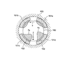
- FIG. 9 is a quotation of FIG. 33 of Patent Document 3.
- a plurality of tilting pads 101 a to 101 d are arranged between the journal 100 and the ring-shaped bearing housing 103 so as to surround the journal 100, and support the journal 100.
- a gap 102 between the journal 100 and the tilting pads 101a to 101d is filled with lubricating oil.
- the oil film pressure Fp varies depending on the direction and position of the load W of the journal 100. When the oil film pressure Fp generated in each of the tilting pads 101a to 101d is integrated over the entire circumference, it matches the load W of the journal 100.
- a plurality of load support portions are provided in the circumferential direction between the bearing base and the bearing housing.
- a bearing housing is supported and fixed by the bearing stand via the load support portion.
- the load support portion is provided at the same circumferential position as the position of the spherical pivot that locally receives the load of the journal, thereby increasing the support strength of the bearing housing.
- a conduction path for the lubricating oil is arranged from the bearing base to the bearing housing through the load support portion which is a connection portion between the bearing base and the bearing housing.
- FIG. 6 of Patent Document 1 another load support portion (spherical liner 06 provided immediately below the journal) is provided at a position removed from the load support portion in the circumferential direction, and lubricating oil is applied to the load support portion.
- positioned the conduction path is disclosed. Since the arrangement position of the conduction path is a place where the tilting pad is not arranged, there is a problem that the journal support strength of the bearing housing is reduced at the arrangement position of the conduction path.
- the load support portions are evenly distributed and arranged at four locations in the circumferential direction of the bearing housing.
- the load is evenly shared by the load support portions. , High assembly accuracy is required.
- JP-A-5-332355 Japanese National Patent Publication No. 10-503827 JP 2000-274432 A JP 2006-112499 A
- the present invention supplies lubricating oil to the tilting pad bearing surface without reducing the strength and size of the journal bearing and maintaining the ease of assembly of the journal bearing.
- An object is to realize an oil supply mechanism that can be reliably performed.
- the journal bearing of the present invention comprises: A bearing base, an annular bearing housing supported by a plurality of load support portions arranged in the circumferential direction by the bearing base, and a journal that is swingably disposed in the bearing housing and supports the journal in an automatically aligning manner.
- a journal bearing comprising a plurality of pads and an oil supply mechanism for supplying lubricating oil to the bearing surface of the pads
- a connecting portion for connecting the bearing stand and the bearing housing at a position separated from the load supporting portion in the circumferential direction is provided, and an upstream oil supply passage provided in the bearing stand at the connecting portion and a downstream side provided in the bearing housing.
- Lubricating oil is supplied from the bearing stand to the bearing surface by drilling an oil supply hole for communicating the oil supply passage; A part of the load of the bearing housing loaded on the bearing stand is supported via the connection portion, and the load sharing is smaller than the load of the bearing housing loaded on the bearing stand via the load support portion. It is composed.
- a connecting portion different from the load supporting portion is provided at a position deviated from the load supporting portion in the circumferential direction, an oil supply hole is provided in the connecting portion, and no oil supply hole is provided in the load supporting portion. Therefore, it is possible to prevent a decrease in strength at the load support portion and to prevent the bearing housing from becoming thick. Further, the load of the bearing housing applied to the bearing stand at the connection portion is configured to be smaller than the load of the bearing housing applied to the bearing stand via the load support portion, thereby reducing the load sharing of the connection portion. By doing so, the load supporting portion is not increased excessively, so that the ease of assembling the journal bearing can be maintained.
- the connecting portion may be provided in a lower bearing housing in which the journal's own weight is loaded.
- the upper bearing housing may be manufactured separately from the lower bearing housing in order to facilitate handling when installing the journal, and may be used as a lid that covers the upper part of the journal. It is inappropriate for the installation position. Further, the upper bearing housing may not be provided with a bearing base. Further, since the journal's own weight is not applied to the upper bearing housing, oil leakage from the oil supply hole is eliminated at the connection portion, and further, the load of the bearing housing loaded on the bearing stand at the connection portion is passed through the load support portion. Therefore, it is not easy to adjust the load to be smaller than the load of the bearing housing loaded on the bearing stand.
- connection portion having the oil supply hole is configured by an O-ring or an elastic body, so that the load of the bearing housing loaded on the bearing surface through the connection portion passes through the load support portion. It is preferable that the load is less than the load of the bearing housing loaded on the bearing stand.
- journal bearing of the present invention is a direct lubrication type journal bearing that supplies lubricating oil to the bearing surface of the pad from an oil supply nozzle provided upstream in the journal rotation direction with respect to the pad
- the journal bearing is provided in the bearing housing.
- the downstream oil supply passage communicates with a first oil introduction hole that is disposed in the bearing housing in the circumferential direction and communicates with an oil supply hole formed in the connection portion, and the first oil introduction hole and the nozzle opening of the oil supply nozzle. It is good to comprise from a 2nd oil guide hole.
- the lubricating oil introduced from the bearing base to the bearing housing through the oil supply holes drilled in the connecting portion is supplied to the oil supply nozzle through the first oil introduction hole and the second oil introduction hole, whereby the bearing housing is obtained.
- the lubricating oil can be supplied to the oil supply nozzle with a simple configuration without reducing the strength of the oil supply.
- journal bearing According to the journal bearing of the present invention, a bearing base, an annular bearing housing supported by a plurality of load support portions arranged in the circumferential direction by the bearing base, and a swingable arrangement in the bearing housing are provided.
- a journal bearing comprising a plurality of pads that support the journal in a self-aligning manner, and an oil supply mechanism that supplies lubricating oil to the bearing surface of the pad, and a bearing stand at a position that is distant from the load support portion in the circumferential direction.
- Lubricating is provided by providing a connecting portion for connecting the bearing housing and providing an oil supply hole in the connecting portion for communicating the upstream oil supply passage provided in the bearing stand and the downstream oil supply passage provided in the bearing housing.
- Oil is supplied to the bearing surface from the bearing base, and the load of the bearing housing loaded on the bearing base via the connection portion is applied to the bearing base via the load support portion.
- the load By configuring the load to be smaller than the weight, the lubricant oil can be supplied to the pad bearing surface without causing a decrease in the strength of the load support portion, and therefore, the thickness of the bearing housing can be prevented, and Since the number of load support portions for supporting the bearing housing is not increased, the ease of assembly of the journal bearing can be maintained.
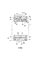
- FIG. 3 is a front sectional view (CC sectional view in FIG. 2) showing an embodiment of the journal bearing of the present invention.
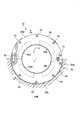
- FIG. 5 is a side sectional view (BB sectional view in FIG. 3) of the embodiment. It is a rear view (view A in FIG. 2) of the embodiment.
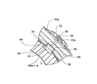
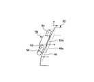
- FIG. 2 is a partially enlarged view of the vicinity of a spherical pivot 36 in FIG. 1. It is a perspective view of the oil supply nozzle 50 of the embodiment.
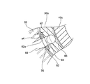
- FIG. 2 is a partially enlarged view of the vicinity of an oil supply hole 60 in FIG. 1.
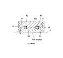
- FIG. 2 is a sectional view taken along line DD in FIG. 1. It is a diagram which shows the mechanical loss of the journal bearing of an oil bath lubrication system. It is explanatory drawing which shows the oil film pressure formation of the journal bearing by a wedge film effect.
- FIG. 1 is a front sectional view taken along the line CC in FIG. 2, and FIG. 2 is a sectional side view taken along the line BB in FIG.
- FIG. 3 and FIG. 3 are rear views seen from the direction A in FIG.
- a journal j is a rotating shaft of a large rotating machine such as a steam turbine, a gas turbine, or a generator. Since the journal j has a large diameter of about 40 cm, the journal bearing 10 that supports the journal j is enlarged and the peripheral speed of the journal j is also increased. Journal j rotates in the direction of arrow a.
- the journal bearing 10 for supporting the journal j includes a bearing base 20, a split-type bearing housing 30 fixedly supported on the bearing base 20, and four tilting pads 40a to 40d attached to the inner surface of the bearing housing 30. It consists of and. In the following, when description common to all the tilting pads is performed, the display is omitted from a to d. The same applies to other members.
- the bearing stand 20 has a recess 20a having a semicircular cross section, while the split bearing housing 30 is divided into an upper bearing housing 30a and a lower bearing housing 30b each having a semi-ring shape.
- the lower bearing housing 30b is fitted and fixed to 20a.
- the upper bearing housing 30 a is positioned on the lower bearing housing 30 b with the positioning pins 31 shown in FIG. 3 and is coupled to the lower bearing housing 30 b by the coupling bolt 32.
- a recess 42 is formed near the center of the back surface of each tilting pad 40, and an adjustment liner 44 is press-fitted into the recess.
- a recess 34 is provided on the inner surface of the bearing housing facing the adjustment liner 44, and a spherical pivot 36 is fitted in the recess.
- the surface of the spherical pivot 36 facing the adjustment liner 44 is formed in a spherical shape, and the tilting pad 40 is swingable in the circumferential direction and the axial direction of the journal j along the spherical surface.
- gaps s ⁇ b> 1 are provided between the tilting pads 40 at equal intervals.
- the center point of the spherical pivot 36 is arranged at a circumferential position of 45 degrees from the vertical direction or the horizontal direction.
- the spherical surface of the spherical pivot 36 is formed at the same height as the inner peripheral surface of the bearing housing 30. Therefore, when the side plate 35 described later is removed, the tilting pad 40 can be removed from the bearing assembly by sliding the tilting pad 40 in the journal axis direction with the adjustment liner 44 attached.
- the upper bearing housing 30a is provided with a measurement hole 38 that communicates the recess 34 and the outer peripheral surface of the upper bearing housing 30a in the radial direction of the journal j.
- An outer liner 33 (load support portion) is provided on the outer peripheral surface of the bearing housing 30 that is in the same circumferential position as the circumferential position where the spherical pivot 36 is provided.
- the outer liner 33 is formed with a through hole 33 a communicating with the measurement hole 38.
- the measurement hole 38 is closed with a plug 39 after a predetermined measurement operation described later is finished.
- the outer liner 33 is coupled to the outer peripheral surface of the bearing housing 30 by a coupling bolt (not shown).
- the outer peripheral surface of the outer liner 33 protrudes slightly outward from the outer peripheral surface of the bearing housing 30. Therefore, the outer liner 33 is in contact with the bearing base 20, and the lower bearing housing 30 b is fixedly supported on the bearing base 20 via the outer liner 33.
- a gap s ⁇ b> 2 exists between the outer peripheral surface of the lower bearing housing 30 b and the inner peripheral surface of the bearing stand 20.
- ring-shaped side plates 35 are disposed on both sides of the bearing housing 30 and the tilting pad 40 in the journal axis direction over the entire circumference.
- the side plate 35 is coupled to the bearing housing 30 with a plurality of bolts 37 arranged in the circumferential direction.
- a gap s3 is provided between the side plate 35 and the journal j. Lubricating oil ejected from an oil supply nozzle 50, which will be described later, is used for lubrication between the journal j and the tilting pad 40 and is then discharged from the gap s3.
- the oil supply nozzles 50 for ejecting the lubricating oil are arranged before and after the journaling direction of the tilting pads 40 so as to sandwich the respective tilting pads 40.
- FIG. 5 shows, as an example, an oil supply nozzle 50 arranged behind the tilting pad 40 in the journal rotation direction.
- the oil supply nozzle 50 has no structural difference due to the difference in the upstream or downstream side of the journal rotation direction.
- the lower half of the main casing 52 having a rectangular parallelepiped shape is fitted and fixed to the fitting recess 70 provided in the bearing housing 30, and the upper half of the oil supply nozzle 50 stands from the bearing housing 30 toward the tilting pad 40 side. It is installed.
- Arms 54 extend from the main casing 52 on both sides in the journal axial direction. Lubricating oil supply holes 56 are formed in the main casing 52 and the arms 54.
- the arm 54 is provided with a plurality of nozzle openings 58 at equal intervals in the axial direction, and the nozzle openings 58 are directed to the journal j side.
- Lubricating oil ejected from an oil supply nozzle 50 provided on the upstream side of the journal rotation direction with respect to the tilting pad 40 is caused by the rotational force of the journal j and the inner peripheral surface of the tilting pad 40 (bearing surface 48 in FIG. 4) and the journal.
- An oil film is formed between the outer peripheral surfaces of j.
- the lubricating oil ejected from the oil supply nozzle 50 provided on the downstream side in the journal rotation direction with respect to the tilting pad 40 cools the lubricating oil that has passed between the tilting pad 40 and the journal j, and the flow of the lubricating oil is reduced.
- the lubricating oil is discharged from the gap s3 between the side plate 35 and the journal j.
- the main casing 52 is a rectangular parallelepiped, and the surface 52a and the inclined surface 46 of the main casing 52 and the tilting pad 40 that face each other are in line contact with each other at the root portion 46a. , And is inclined so as to form a minute angle ⁇ in a direction away from the surface 52a.
- the oil supply nozzle 50 is tilted by supporting the base portion 46a of the inclined surface 46 of the tilting pad 40 in line contact with the surface 52a of the main casing 52 from both sides in the journal rotation direction of the tilting pad 40. The movement of the pad 40 in the journal rotation direction is fixedly supported.
- the bearing base 20 is provided with a lubricating oil supply hole 60.
- An outer liner 62 (connection portion) is provided on the outer peripheral surface of the lower bearing housing 30 b facing the oil supply hole 60.
- an oil supply hole 62 a is formed in the outer liner 62 at a position communicating with the oil supply hole 60 in the journal radial direction.
- an oil supply hole 64 is formed in a journal radial direction at a position communicating with the oil supply hole 62a.
- an annular oil guide groove 66 is provided in communication with the oil supply hole 64 in the journal rotation direction.
- the oil guide groove 66 is provided in the entire circumference in the bearing housing 30. As shown in FIG. 2, the oil guide groove 66 is formed in an oil supply hole 56 formed in the main casing 52 of the oil supply nozzle 50 via an oil supply hole 68 formed in the bearing housing 30 in the journal axis direction. Communicate. One end opening of the oil supply hole 56 is closed by a plug 72, and the plug 72 is fixed to the opening by a C-shaped retaining ring 74.
- a gap s4 is formed between the inner surface of the bearing stand 20 and the outer surface of the outer liner 62.
- the O-ring 76 is inserted into the gap s4, and a crushing margin is provided in the O-ring 76 to seal the gap s4.
- the lubricating oil is prevented from leaking from the gap s4, and the load on the lower bearing housing 30b applied to the bearing base 20 via the outer liner 62 is applied to the bearing base 20 via the outer liner 33.
- the load is smaller than that of the bearing housing 30b.
- cylindrical recesses 82 are formed in the inner peripheral surface of the upper bearing housing 30a at two locations facing the outer peripheral surface of the tilting pad 40a or 40b.
- a cylindrical recess 84 having the same diameter as the recess 82 is formed on the outer peripheral surface of the tilting pad 40a or 40b facing the recess 82.
- a coil spring 80 is fitted into the recess 82 and the recess 84. As a result, the elastic force of the coil spring 80 is urged toward the journal j.
- the coil spring 80 is provided on the downstream end of the tilting pad 40a or 40b in the journal rotation direction. Therefore, it becomes easy to form a narrow gap between the surface of the journal j and the tilting pad 40a or 40b in the journal rotation direction as shown in FIG.
- screw holes 90 are formed in the radial direction at the upstream end and the downstream end in the journal rotation direction of each tilting pad 40.
- a bolt through hole 92 is formed in a radial direction at a position corresponding to the opening of the screw hole 90 of the bearing housing 30.
- the axis of the screw hole 90 and the bolt through hole 92 are provided so as to coincide with each other.
- a hexagon socket head bolt 94 is passed through the bolt through hole 92 and the tip of the hexagon socket head bolt 94 is screwed into the screw hole 90.
- the gap between the bearing housing 30 and the tilting pad 40 can be adjusted by adjusting the length of the threaded portion of the hexagon socket head bolt 94 to the screw hole 90. Thereby, the gap dimension between the journal surface and the tilting pad 40 can be adjusted. In this way, the clearance between the tilting pad 40 and the journal j at the front and rear ends in the rotational direction can be adjusted with simple and low-cost means.
- the lubricating oil is supplied to the oil supply nozzle 50 from the oil supply hole 60 provided in the bearing stand 20 through the oil guide groove 66 and the oil supply holes 68 and 56. Then, the lubricating oil is supplied to the inner peripheral surface (bearing surface 48) of the tilting pad 40 from the nozzle port 58 of the arm 54 of the oil supply nozzle 50.
- Lubricating oil ejected from an oil supply nozzle 50 disposed on the upstream side in the journal rotation direction with respect to the tilting pad 40 is supplied to the bearing surface 48 and used for lubrication of the bearing surface 48.
- Lubricating oil ejected from the oil supply nozzle 50 disposed downstream of the journal rotation direction cools the lubricating oil that has passed through the bearing surface 48 and disturbs the laminar flow of the lubricating oil formed on the surface of the journal j.
- the high temperature of the lubricating oil on the bearing surface 48 can be suppressed, and burning of the bearing surface 48 can be suppressed.
- the gap between the bearing surface 48 of the tilting pad and the surface of the journal j can be measured by measuring the distance from the back surface of the spherical pivot 36 to the opening of the measurement hole 38 using a known measuring device. Then, based on this measured value, as shown in FIG. 4, the gap between the bearing surface 48 and the journal can be adjusted to a desired dimension by inserting a height adjusting shim plate 86 on the back surface of the spherical pivot 36. .
- this clearance adjustment means together with clearance adjustment by the hexagon socket head cap bolt 94, the clearance between the bearing surface 48 and the journal j is narrowed toward the journal rotation direction with high accuracy as shown in FIG. Since the gap can be formed, a high oil film pressure can be formed on the bearing surface 48 by utilizing the wedge film effect. Therefore, the lubricating performance of the bearing surface 48 can be maintained high.
- the coil spring 80 is provided downstream of the tilting pad 40a or 40b provided in the upper bearing housing 30a in the journal rotation direction, and the elastic force of the coil spring 80 is applied to the journal j.
- the journal j is not loaded with its own weight on the upper bearing housing 30a, vibration tends to occur in the related art, and there is a possibility that fatigue destruction may occur in the tilting pad 40 due to the vibration. Can also be eliminated.
- the oil supply nozzle 50 is provided on the upstream side and the downstream side in the rotation direction of each tilting pad 40, and the base part of the inclined surface 46 of the tilting pad 40 is supported in line contact by the base part 46a of the main casing 52.
- a means for fixing the tilting pad 40 in the journal rotation direction is not required, and the configuration of the journal bearing can be simplified.
- the tilting pad 40 is supported by the base portion 46a of the main casing 52, the front and rear spaces of the tilting pad 40 can be widened, thereby enabling further stable supply of lubricating oil. Become.
- the spherical pivot 36 is protruded toward the tilting pad 40 and the tilting pad 40 is fixed, but this configuration is not necessary in the present embodiment. Therefore, by making the surface of the spherical pivot 36 the same height as the inner peripheral surface of the bearing housing 30, the tilting pad 40 can be pulled out in the journal axis direction simply by removing the side plate 35. Therefore, it is possible to remove the tilting pad 40 with the journal j installed, and it becomes easy to attach and remove the tilting pad 40 when the tilting pad 40 is repaired or modified.
- the outer liner 62 is provided separately from the outer liner 33 that is the load support portion of the bearing housing 30, and the outer liner 62 is provided with the oil supply hole 62 a, thereby preventing the strength of the outer liner 33 from being lowered. Therefore, the thickness of the bearing housing 30 can be prevented. Further, since the load of the bearing housing 30 supported by the outer liner 62 is less than the load of the bearing housing 30 supported by the outer liner 33, the oil supply hole 62a can be provided without increasing the number of the outer liners 33 excessively. It becomes possible. Therefore, since there is no change in the number of outer liners 33, it is not necessary to increase the dimensional accuracy of the outer liners 33, and the ease of assembling the journal bearing can be maintained.
- the outer liner 62 is provided in the lower bearing housing 30b to which the load of the journal j is loaded, the load applied to the lower bearing housing 30b via the outer liner 62 can be easily adjusted, and the outer liner 62 and Since the deformable and elastic O-ring 76 is attached to the connection portion of the bearing stand 20, the load load can be adjusted more easily.
- Lubricating oil is supplied to the oil supply nozzle 50 from the oil supply hole 60 provided in the bearing stand 20 through the annular oil guide groove 66 and the oil supply hole 68 and the oil supply hole 56 formed in the oil supply nozzle 50. Therefore, the lubricating oil can be supplied to the oil supply nozzle 50 with a simple configuration without reducing the strength of the bearing housing 30.
- the elastic body is not limited to the O-ring, and for example, an accordion structure may be used.
- an elastic body it becomes easy to adjust the load of the bearing housing 30 loaded on the bearing stand 20 via the outer liner 62.
- the lubricating oil in a journal bearing having an oil supply mechanism that supplies lubricating oil to the bearing surface of the tilting pad, the lubricating oil can be supplied to the bearing surface without causing a decrease in strength or an increase in size of the journal bearing. It can be performed reliably, and is suitable for being applied to large-sized rotating structures such as steam turbines, gas turbines, and generators.
Landscapes
- Engineering & Computer Science (AREA)
- General Engineering & Computer Science (AREA)
- Mechanical Engineering (AREA)
- Physics & Mathematics (AREA)
- Fluid Mechanics (AREA)
- Chemical & Material Sciences (AREA)
- Oil, Petroleum & Natural Gas (AREA)
- Sliding-Contact Bearings (AREA)
Abstract
ジャーナル軸受の強度低下や大型化を招くことなく、ジャーナル軸受の組立の容易さを保持しつつ、ティルテイングパッド軸受面への潤滑油の供給を確実に行なう。軸受台20と、該軸受台により複数の荷重支持部33で支持される環状の軸受ハウジング30と、該軸受ハウジング内に揺動可能に配設されジャーナルjを自動調心可能に支持する複数のパッド40a~dと、該パッドの軸受面48に潤滑油を供給する給油機構とを備えたジャーナル軸受10において、荷重支持部33と周方向に外れた位置で軸受台20と軸受ハウジング30とを接続する接続部62を設けると共に、該接続部に軸受台20に設けられた上流側給油路60と軸受ハウジング30に設けられた下流側給油路66を連通させる給油孔62a、64を穿設し、接続部62を介して軸受台20に負荷される軸受ハウジング30の荷重が荷重支持部33を介する荷重よりも小さくなるように構成した。
Description
本発明は、例えば蒸気タービン、ガスタービン、発電機等の大型回転構造体に適用されて好適であり、回転構造体の回転軸を支承するパッド型ジャーナル軸受に関する。
従来、この種のジャーナル軸受には、ジャーナルの自動調心が可能なティルテイングパッドを備えたジャーナル軸受が用いられている。
特許文献1(特開平5-332355号公報)に、本出願人が提案した、ティルテイングパッドを備えたジャーナル軸受が開示されている。特許文献1に開示されているように、ティルテイングパッドは、ジャーナルに対してティルテイングパッドの背面側に設けられた球面ピボットに調整ライナを介してジャーナルの軸方向及び周方向に揺動可能に支持されている。
特許文献1(特開平5-332355号公報)に、本出願人が提案した、ティルテイングパッドを備えたジャーナル軸受が開示されている。特許文献1に開示されているように、ティルテイングパッドは、ジャーナルに対してティルテイングパッドの背面側に設けられた球面ピボットに調整ライナを介してジャーナルの軸方向及び周方向に揺動可能に支持されている。
従って、ティルテイングパッドは、ジャーナルの動きに対して自由に動くことができ、ティルテイングパッドを備えたジャーナル軸受は自動調心機能をもつ。そのため、ジャーナルを安定して支持できるため、高速回転機械に適用されている。
また、球面ピボットは軸受ハウジングの内面からティルテイングパッド側に突出し、ティルテイングパッド背面に設けられた凹溝に遊嵌しているため、ティルテイングパッドがジャーナルの回転方向に連れ回りするのを球面ピボットで阻止している。
また、球面ピボットは軸受ハウジングの内面からティルテイングパッド側に突出し、ティルテイングパッド背面に設けられた凹溝に遊嵌しているため、ティルテイングパッドがジャーナルの回転方向に連れ回りするのを球面ピボットで阻止している。
なお、ティルテイングパッドの支持構造として、調整ライナや球面ピボットの代わりに、特許文献2(特表平10-503827号公報)に開示されているように、位置決めソケット42と、スピゴット部材40及びプラットホーム胴部材23等で構成される位置決め手段24からなる支持構造が採用されることもある。
ティルテイングパッドを備えたジャーナル軸受には、油浴潤滑方式と直接潤滑方式とがある。油浴潤滑方式は、ティルテイングパッドの両側をサイドシールで密閉して、ティルテイングパッドの軸受面を潤滑油で満たすようにした方式である。
しかし、この方式では、サイドシールによる摩擦損失と、パッド間における潤滑油の攪拌損失が生じ、機械効率が低下するという問題がある。
しかし、この方式では、サイドシールによる摩擦損失と、パッド間における潤滑油の攪拌損失が生じ、機械効率が低下するという問題がある。
この機械効率の低下を特許文献1の図8を引用して説明する。図8は特許文献1の図8に図示された、油浴潤滑方式におけるジャーナル軸受のジャーナル回転数と機械損失との関係を示す線図である。図8において、全機械損失は略回転数の2乗に比例して増大するが、その内訳は、ジャーナル軸受の自重が負荷される下側パッドによる摩擦損失Xと、無負荷側の上側パッドによる摩擦損失Yと、サイドシールによる摩擦損失及びパッド間における潤滑油の攪拌損失を加算した機械損失Zとに分けられる。
そこで、機械損失Zをなくした直接潤滑方式が提案されている。直接潤滑方式は、各ティルテイングパッドのジャーナル回転方向上流側に給油ノズルを設け、該給油ノズルからティルテイングパッドの軸受面に潤滑油を供給する方式であり、これによって、サイドシールを不要としたものである。直接潤滑方式では、機械損失Zを解消できるので、現在では広く使用されている。なお、特許文献1は、直接潤滑方式のジャーナル軸受を提案するものである。
特許文献3(特開2000-274432号公報)は、別な構成の直接潤滑方式のジャーナル軸受を提案するものである。特許文献3の段落〔0009〕に記載されているように、ティルテイングパッドを備えたジャーナル軸受には、潤滑油のキャリオーバという問題もある。これは、上流側のティルテイングパッドの軸受面に供給された潤滑油がジャーナル表面に連れ回りして、下流側のティルテイングパッドの軸受面に入り込む現象を言う。
潤滑油は、ティルテイングパッドの軸受面でせん断力を受け温度が上昇するため、複数のティルテイングパッドの軸受面に入り込むことで、該軸受面周辺が高温となる。そして、ティルテイングパッドの温度を上昇させ、軸受部の焼損を招く場合がある。
特許文献3は、直接潤滑方式のジャーナル軸受で、キャリオーバを防ぐ手段を提案している。
特許文献3は、直接潤滑方式のジャーナル軸受で、キャリオーバを防ぐ手段を提案している。
また、特許文献4(特開2006-112499号公報)には、直接潤滑方式のジャーナル軸受で、潤滑油のキャリオーバによるティルテイングパッドの温度上昇を防ぐ別な手段が提案されている。この手段は、ティルテイングパッドのジャーナル回転方向上流側及び下流側に給油ノズルを設けると共に、ティルテイングパッドに周方向に冷却流路を設け、該冷却流路にジャーナル回転方向下流側に設けられた給油ノズルから潤滑油を流通させることにより、ティルテイングパッドの表面温度の上昇を抑えるようにしたものである。
また、特許文献3の段落〔0004〕に記載されているように、パッド型ジャーナル軸受では、ジャーナル表面とティルテイングパッド間には潤滑油が満たされているが、ティルテイングパッドは静止し、ジャーナルは非常な高周速で回転しているため、ティルテイングパッドとジャーナル軸受間には大きな速度差が発生する。
この速度差に抗して、ジャーナル表面とティルテイングパッド間にティルテイングパッドに負荷される荷重を支承する油膜圧を形成する必要がある。
この速度差に抗して、ジャーナル表面とティルテイングパッド間にティルテイングパッドに負荷される荷重を支承する油膜圧を形成する必要がある。
図9は、特許文献3の図33を引用したものである。図9において、ジャーナル100とリング状の軸受ハウジング103の間に、ジャーナル100を取り囲むように複数のティルテイングパッド101a~dが配置され、ジャーナル100を支承している。ジャーナル100とティルテイングパッド101a~dとの隙間102には、潤滑油が満たされている。油膜圧Fpは、ジャーナル100の荷重Wの方向及び位置により変化するが、各ティルテイングパッド101a~dに発生する油膜圧Fpを全周積分すると、ジャーナル100の荷重Wに一致する。
各ティルテイングパッド101a~dを傾け、ジャーナル回転方向aの下流側の隙間102を狭めることにより、くさび膜効果により、下流側の隙間102に高い油膜圧を形成できる。
また、特許文献1の図1、図3及び図6に図示されているように、軸受台と軸受ハウジングとの間には、周方向に複数の荷重支持部(球面ライナ06)が設けられ、軸受台によって該荷重支持部を介して軸受ハウジングが支持固定されている。該荷重支持部は、ジャーナルの荷重を局所的に受ける球面ピボットの配置位置と同一周方向位置に設けられることで、軸受ハウジングの支持強度を高めている。
一方、軸受台から軸受ハウジングに潤滑油を供給するため、軸受台と軸受ハウジングの接続部である該荷重支持部を通して、軸受台から軸受ハウジングに潤滑油の導通路が配置されている。
一方、軸受台から軸受ハウジングに潤滑油を供給するため、軸受台と軸受ハウジングの接続部である該荷重支持部を通して、軸受台から軸受ハウジングに潤滑油の導通路が配置されている。
しかし、ジャーナルの荷重を受ける荷重支持部に給油孔(潤滑油の導通路)を配置すると、該荷重支持部の強度が低下すると共に、該荷重支持部の半径方向内側には、特許文献1や特許文献2に開示されたティルテイングパッド支持部材が配置されているため、この部分の構造が複雑になるという問題がある。また、この強度低下に対し、軸受ハウジングの肉厚を大きくする必要があり、このため、ジャーナル軸受が大型化するという問題がある。
特許文献1の図6には、該荷重支持部から周方向に外した位置に別な荷重支持部(ジャーナルの直下方に設けられた球面ライナ06)を設け、この荷重支持部に潤滑油の導通路を配置した構成が開示されている。該導通路の配置位置がティルテイングパッドが配設されていない箇所であるので、該導通路の配置位置で軸受ハウジングのジャーナル支持強度が低下するという問題がある。
荷重支持部は、通常、軸受ハウジングの周方向4箇所に均等に分散配置されるが、特許文献1のように、荷重支持部が5箇所になると、荷重を荷重支持部で均等負担するために、高い組立精度を必要とする。
本発明は、かかる従来技術の課題に鑑み、ジャーナル軸受の強度低下や大型化を招くことなく、かつジャーナル軸受の組立の容易さを保持しつつ、ティルテイングパッド軸受面への潤滑油の供給を確実に行なうことができる給油機構を実現することを目的とする。
前記目的を達成するため、本発明のジャーナル軸受は、
軸受台と、該軸受台により周方向に配置された複数の荷重支持部で支持される環状の軸受ハウジングと、該軸受ハウジング内に揺動可能に配設されジャーナルを自動調心可能に支持する複数のパッドと、該パッドの軸受面に潤滑油を供給する給油機構とを備えたジャーナル軸受において、
前記荷重支持部と周方向に外れた位置で軸受台と軸受ハウジングとを接続する接続部を設けると共に、該接続部に軸受台に設けられた上流側給油路と軸受ハウジングに設けられた下流側給油路を連通させる給油孔を穿設することによって、潤滑油を軸受台から前記軸受面に供給するようにし、
該接続部を介して軸受台に負荷される軸受ハウジングの荷重の一部を支持するとともに、前記荷重支持部を介して軸受台に負荷される軸受ハウジングの荷重よりも小さい荷重分担になるように構成したものである。
軸受台と、該軸受台により周方向に配置された複数の荷重支持部で支持される環状の軸受ハウジングと、該軸受ハウジング内に揺動可能に配設されジャーナルを自動調心可能に支持する複数のパッドと、該パッドの軸受面に潤滑油を供給する給油機構とを備えたジャーナル軸受において、
前記荷重支持部と周方向に外れた位置で軸受台と軸受ハウジングとを接続する接続部を設けると共に、該接続部に軸受台に設けられた上流側給油路と軸受ハウジングに設けられた下流側給油路を連通させる給油孔を穿設することによって、潤滑油を軸受台から前記軸受面に供給するようにし、
該接続部を介して軸受台に負荷される軸受ハウジングの荷重の一部を支持するとともに、前記荷重支持部を介して軸受台に負荷される軸受ハウジングの荷重よりも小さい荷重分担になるように構成したものである。
本発明では、荷重支持部から周方向に外れた位置に荷重支持部とは別な接続部を設け、該接続部に給油孔を穿設し、荷重支持部には給油孔を穿設しないことによって、荷重支持部での強度低下を防止し、軸受ハウジングの厚肉化を防止できる。
また、該接続部で軸受台に負荷される軸受ハウジングの荷重が荷重支持部を介して軸受台に負荷される軸受ハウジングの荷重よりも小さくなるように構成し、該接続部の荷重分担を少なくすることによって、荷重支持部を余分に増やさないようにしたため、ジャーナル軸受の組立の容易さを保持できるようにしている。
また、該接続部で軸受台に負荷される軸受ハウジングの荷重が荷重支持部を介して軸受台に負荷される軸受ハウジングの荷重よりも小さくなるように構成し、該接続部の荷重分担を少なくすることによって、荷重支持部を余分に増やさないようにしたため、ジャーナル軸受の組立の容易さを保持できるようにしている。
本発明のジャーナル軸受において、前記接続部をジャーナルの自重が負荷される下側軸受ハウジングに設けるとよい。上側軸受ハウジングは、ジャーナル設置時の取り扱いを容易にするため、下側軸受ハウジングと分離して製造される場合もあり、ジャーナルの上部を覆う蓋体として用いられる場合もあるため、該接続部の設置位置としては不適当である。また、上側軸受ハウジングには軸受台を設けない場合もある。
また、上側軸受ハウジングにはジャーナルの自重が負荷されないため、該接続部で給油孔からの油漏れをなくし、さらに、該接続部で軸受台に負荷される軸受ハウジングの荷重が荷重支持部を介して軸受台に負荷される軸受ハウジングの荷重よりも小さい荷重分担になるように調整するのが容易でない。
また、上側軸受ハウジングにはジャーナルの自重が負荷されないため、該接続部で給油孔からの油漏れをなくし、さらに、該接続部で軸受台に負荷される軸受ハウジングの荷重が荷重支持部を介して軸受台に負荷される軸受ハウジングの荷重よりも小さい荷重分担になるように調整するのが容易でない。
一方、下側軸受ハウジングでは、ジャーナルの自重が負荷されるため、該接続部に負荷される荷重が荷重支持部で負荷される荷重より小さい荷重分担になるように調整するのが容易である。従って、該接続部を下側軸受ハウジングに設けたほうが組立が容易になる。
また、本発明のジャーナル軸受において、給油孔を有する接続部をOリング又は弾性体で構成することにより、該接続部を介して軸受面に負荷される軸受ハウジングの荷重が前記荷重支持部を介して軸受台に負荷される軸受ハウジングの荷重よりも小さい荷重分担になるように構成するとよい。
該接続部を変形が可能で弾力性のあるOリング又は弾性体で構成することにより、該接続部で軸受台に負荷される軸受ハウジングの荷重を調整するのが容易になり、組立が容易になる。
該接続部を変形が可能で弾力性のあるOリング又は弾性体で構成することにより、該接続部で軸受台に負荷される軸受ハウジングの荷重を調整するのが容易になり、組立が容易になる。
また、本発明のジャーナル軸受が、パッドに対しジャーナル回転方向上流側に設けられた給油ノズルからパッドの軸受面に潤滑油を供給する直接潤滑方式のジャーナル軸受である場合に、軸受ハウジングに設けられる下流側給油路が、軸受ハウジングに周方向に配置され前記接続部に穿設された給油孔に連通する第1導油孔と、該第1導油孔と給油ノズルのノズル口とに連通する第2導油孔とから構成されるようにするとよい。
かかる構成により、接続部に穿設された給油孔を通して軸受台から軸受ハウジングに導入した潤滑油を、第1導油孔及び第2導油孔を介して給油ノズルに供給することにより、軸受ハウジングの強度を低下させずに、簡潔な構成で給油ノズルに潤滑油を供給できる。
本発明のジャーナル軸受によれば、軸受台と、該軸受台により周方向に配置された複数の荷重支持部で支持される環状の軸受ハウジングと、該軸受ハウジング内に揺動可能に配設されジャーナルを自動調心可能に支持する複数のパッドと、該パッドの軸受面に潤滑油を供給する給油機構とを備えたジャーナル軸受において、前記荷重支持部と周方向に外れた位置で軸受台と軸受ハウジングとを接続する接続部を設けると共に、該接続部に軸受台に設けられた上流側給油路と軸受ハウジングに設けられた下流側給油路を連通させる給油孔を穿設することによって、潤滑油を軸受台から前記軸受面に供給するようにし、該接続部を介して軸受台に負荷される軸受ハウジングの荷重が前記荷重支持部を介して軸受台に負荷される軸受ハウジングの荷重よりも小さい荷重分担になるように構成したことにより、前記荷重支持部の強度低下を招くことなく、潤滑油をパッド軸受面に供給でき、従って、軸受ハウジングの厚肉化を防止できると共に、軸受ハウジングを支持する荷重支持部の数を増加させないので、ジャーナル軸受の組立容易性を維持できる。
以下、本発明を図に示した実施形態を用いて詳細に説明する。但し、この実施形態に記載されている構成部品の寸法、材質、形状、その相対配置などは特に特定的な記載がない限り、この発明をそれのみに限定する趣旨ではない。
図1~図3は、本実施形態のジャーナル軸受を示し、図1は図2中のC-C線に沿う正面視断面図、図2は図3中のB-B線に沿う側面視断面図、図3は図2中のA方向から視た背面図である。
図1において、ジャーナルjは、蒸気タービン、ガスタービン又は発電機等の大型回転機械の回転軸である。ジャーナルjは40cm前後にも及ぶ大径となるため、これを支承するジャーナル軸受10も大型化すると共に、ジャーナルjの周速も高速化する。ジャーナルjは矢印a方向に回転する。
図1において、ジャーナルjは、蒸気タービン、ガスタービン又は発電機等の大型回転機械の回転軸である。ジャーナルjは40cm前後にも及ぶ大径となるため、これを支承するジャーナル軸受10も大型化すると共に、ジャーナルjの周速も高速化する。ジャーナルjは矢印a方向に回転する。
ジャーナルjを支承するジャーナル軸受10は、軸受台20と、軸受台20に固定支持される2つ割り型の軸受ハウジング30と、軸受ハウジング30の内面に取り付けられる4個のティルテイングパッド40a~dとで構成されている。なお、以後、すべてのティルテイングパッドに共通の記述を行なう場合、a~dを省いて表示する。これは他の部材についても同様とする。
軸受台20は断面が半円状の凹部20aを有し、一方2つ割り型の軸受ハウジング30は、夫々半リング状をなす上側軸受ハウジング30aと下側軸受ハウジング30bとに分割され、該凹部20aに下側軸受ハウジング30bが嵌合固定される。上側軸受ハウジング30aは、下側軸受ハウジング30bに図3に示す位置決めピン31で位置決めされて、結合ボルト32によって下側軸受ハウジング30bに結合される。
図4に示すように、各ティルテイングパッド40の背面中央付近に凹部42が刻設され、該凹部に調整ライナ44が圧入されている。調整ライナ44に対面する軸受ハウジング内面に凹部34が設けられ、該凹部に球面ピボット36が嵌着されている。
球面ピボット36の調整ライナ44に面する表面は球面状に形成され、ティルテイングパッド40は、該球面に沿ってジャーナルjの周方向及び軸方向に揺動可能になっている。
球面ピボット36の調整ライナ44に面する表面は球面状に形成され、ティルテイングパッド40は、該球面に沿ってジャーナルjの周方向及び軸方向に揺動可能になっている。
図1に示すように、ティルテイングパッド40間には、夫々等間隔に隙間s1が設けられている。球面ピボット36は、その中心点が鉛直方向又は水平方向から45度の周方向位置に配置されている。
図4に示すように、球面ピボット36の球面は、軸受ハウジング30の内周面と同じ高さに形成されている。従って、後述するサイドプレート35を取り外すと、ティルテイングパッド40は、調整ライナ44を付けたままジャーナル軸方向に滑らすことで、ティルテイングパッド40を軸受組立体から取り外すことができる。
図4に示すように、球面ピボット36の球面は、軸受ハウジング30の内周面と同じ高さに形成されている。従って、後述するサイドプレート35を取り外すと、ティルテイングパッド40は、調整ライナ44を付けたままジャーナル軸方向に滑らすことで、ティルテイングパッド40を軸受組立体から取り外すことができる。
上側軸受ハウジング30aには、ジャーナルjの半径方向に向けて、凹部34と上側軸受ハウジング30aの外周面とを連通する測定孔38が穿設されている。球面ピボット36が設けられた周方向位置と同一周方向位置に当る軸受ハウジング30の外周面には、アウタライナ33(荷重支持部)が設けられている。アウタライナ33には測定孔38に連通する貫通孔33aが穿設されている。測定孔38は、後述する所定の測定作業が終わった後で、プラグ39で閉塞される。
アウタライナ33は、図示しない結合ボルトにより軸受ハウジング30の外周面に結合されている。アウタライナ33の外周面は、軸受ハウジング30の外周面よりわずかに外方に突出している。
そのため、アウタライナ33が軸受台20に接し、下側軸受ハウジング30bは、アウタライナ33を介して軸受台20に固定支持される。下側軸受ハウジング30bの外周面と軸受台20の内周面との間には隙間s2が存在する。
そのため、アウタライナ33が軸受台20に接し、下側軸受ハウジング30bは、アウタライナ33を介して軸受台20に固定支持される。下側軸受ハウジング30bの外周面と軸受台20の内周面との間には隙間s2が存在する。
図2に示すように、軸受ハウジング30及びティルテイングパッド40のジャーナル軸方向両側には、全周に亘りリング状のサイドプレート35が配設されている。図3に示すように、サイドプレート35は、周方向に複数配置されたボルト37で軸受ハウジング30に結合されている。サイドプレート35とジャーナルj間に隙間s3が設けられ、後述する給油ノズル50から噴出した潤滑油は、ジャーナルjとティルテイングパッド40間の潤滑に供した後、隙間s3から排出される。
図1に示すように、潤滑油を噴出する給油ノズル50は、各ティルテイングパッド40を挟むように、ティルテイングパッド40のジャーナル回転方向前後に配設されている。図5は、ティルテイングパッド40のジャーナル回転方向後方に配置された給油ノズル50を一例として示す。以下、図2及び図5により給油ノズル50の構成を説明する。給油ノズル50は、ジャーナル回転方向の上流側又は下流側に配置された違いにより構成上の違いはない。
給油ノズル50は、その直方体状をなす主ケーシング52の下半分が軸受ハウジング30に設けられた嵌合用凹部70に嵌合固定され、上半分が軸受ハウジング30からティルテイングパッド40側に向かって立設されている。主ケーシング52からジャーナル軸方向両側に腕54が延設されている。主ケーシング52及び腕54の内部には潤滑油供給孔56が穿設されている。
腕54には、軸方向に等間隔に複数のノズル口58が穿設され、ノズル口58は、ジャーナルj側に向けられている。ティルテイングパッド40に対しジャーナル回転方向上流側に設けられた給油ノズル50から噴出された潤滑油は、ジャーナルjの回転力によりティルテイングパッド40の内周面(図4の軸受面48)とジャーナルjの外周面との間に入り、油膜を形成する。
ティルテイングパッド40に対しジャーナル回転方向下流側に設けられた給油ノズル50から噴出した潤滑油は、ティルテイングパッド40とジャーナルj間を通ってきた潤滑油を冷却すると共に、該潤滑油の流れをノズル口58から噴出した潤滑油で乱し、ジャーナル表面から剥離させることによって、回転方向後側のティルテイングパッド40の軸受面48に連れ回りするのを防止している。潤滑油は、サイドプレート35とジャーナルj間の隙間s3から排出される。
図5に示すように、主ケーシング52は直方体をなし、主ケーシング52とティルテイングパッド40の互いに対面する面52aと傾斜面46とは、根元部46aで線接触しており、傾斜面46は、面52aに対して離れる方向に微小角度αをなすように傾斜している。このように、給油ノズル50は、ティルテイングパッド40のジャーナル回転方向両側から、その主ケーシング52の面52aでティルテイングパッド40の傾斜面46の根元部46aを線接触支持することにより、ティルテイングパッド40のジャーナル回転方向の動きを固定支持している。
図1に示すように、軸受台20には潤滑油の給油孔60が設けられている。給油孔60に対面する下側軸受ハウジング30bの外周面にはアウタライナ62(接続部)が設けられている。以下、この部分の構成を図6により説明する。図6において、アウタライナ62には、給油孔60に連通する位置に、ジャーナル半径方向に給油孔62aが穿設されている。
また、下側軸受ハウジング30bには、給油孔62aに連通する位置に給油孔64がジャーナル半径方向に穿設されている。さらに、給油孔64に連通して、ジャーナル回転方向に環状の導油溝66が設けられている。
また、下側軸受ハウジング30bには、給油孔62aに連通する位置に給油孔64がジャーナル半径方向に穿設されている。さらに、給油孔64に連通して、ジャーナル回転方向に環状の導油溝66が設けられている。
導油溝66は、軸受ハウジング30内で周方向全周に設けられている。図2に示すように、導油溝66は、軸受ハウジング30内にジャーナル軸方向に穿設された給油孔68を介して、給油ノズル50の主ケーシング52内に穿設された給油孔56に連通している。給油孔56の一端開口はプラグ72で閉塞され、プラグ72は該開口にC形止め輪74で固定されている。
軸受台20の内面とアウタライナ62の外面との間には、隙間s4が形成される。隙間s4にOリング76を挿入し、Oリング76につぶし代を設けて隙間s4を密閉する。これによって、隙間s4から潤滑油が漏れるのを防ぐと共に、アウタライナ62を介して軸受台20に付加される下側軸受ハウジング30bの荷重が、アウタライナ33を介して軸受台20に付加される下側軸受ハウジング30bの荷重より小さい荷重分担となるように構成されている。
図7に示すように、上側軸受ハウジング30aの内周面には、ティルテイングパッド40a又は40bの外周面に対面する2箇所に、円筒形の凹部82が穿設されている。また、該凹部82に対面するティルテイングパッド40a又は40bの外周面に凹部82と同径の円筒形凹部84が穿設されている。そして、該凹部82及び凹部84にコイルバネ80が嵌合されている。これによって、コイルバネ80の弾性力がジャーナルj側に付勢される。コイルバネ80は、ティルテイングパッド40a又は40bのジャーナル回転方向下流側端部に設けられている。従って、ジャーナルjの表面とティルテイングパッド40a又は40bとの間に、図9に示すように、ジャーナル回転方向に向かって先狭まりの隙間を形成するのが容易になる。
また、図1に示すように、各ティルテイングパッド40のジャーナル回転方向上流側端及び下流側端には、半径方向にネジ穴90が穿設されている。そして、軸受ハウジング30の該ネジ穴90の開口に一致する位置に、半径方向にボルト通し孔92が穿設されている。ネジ孔90とボルト通し孔92の軸線は一致するように設けられている。該ボルト通し孔92に六角穴付きボルト94を通し、六角穴付きボルト94の先端部をネジ穴90に螺合させる。
六角穴付きボルト94のネジ穴90への螺合部の長さを調整することにより、軸受ハウジング30とティルテイングパッド40との隙間を調整できる。これによって、ジャーナル表面とティルテイングパッド40間の隙間寸法を調整することができる。
このように、簡素かつ低コストな手段で、ティルテイングパッド40の回転方向前後端のジャーナルjとの隙間を調整可能になる。
このように、簡素かつ低コストな手段で、ティルテイングパッド40の回転方向前後端のジャーナルjとの隙間を調整可能になる。
かかる構成の本実施形態において、軸受台20に設けられた給油孔60から導油溝66及び給油孔68,56を経て、給油ノズル50に潤滑油が供給される。そして、潤滑油は給油ノズル50の腕54のノズル口58から、ティルテイングパッド40の内周面(軸受面48)に供給される。
ティルテイングパッド40に対してジャーナル回転方向上流側に配設された給油ノズル50から噴出された潤滑油は、軸受面48に供給され、軸受面48の潤滑に供される。ジャーナル回転方向下流側に配設された給油ノズル50から噴出した潤滑油は、軸受面48を通ってきた潤滑油を冷却すると共に、ジャーナルjの表面に形成された潤滑油の層流を乱すことで、高温となった潤滑油が下流側の軸受面48に連れ回りするのを抑制できる。これによって、軸受面48の潤滑油の高温化を抑制し、軸受面48の焼損を抑制できる。
このとき、公知の測定機器を用い、球面ピボット36の背面から測定孔38の開口までの距離を測定することによって、ティルテイングパッドの軸受面48とジャーナルjの表面間の隙間を測定できる。そして、この測定値に基づいて、図4に示すように、球面ピボット36の背面に高さ調整用シム板86を挿入することによって、軸受面48とジャーナル間の隙間を所望の寸法に調整できる。
この隙間調整手段と、六角穴付きボルト94による隙間調整を併用することによって、軸受面48とジャーナルj間の隙間を、図9に示すように、高精度でジャーナル回転方向に向かって先狭まりの隙間とすることができるので、くさび膜効果を利用して軸受面48に高い油膜圧を形成できる。従って、軸受面48の潤滑性能を高く維持できる。
この隙間調整手段と、六角穴付きボルト94による隙間調整を併用することによって、軸受面48とジャーナルj間の隙間を、図9に示すように、高精度でジャーナル回転方向に向かって先狭まりの隙間とすることができるので、くさび膜効果を利用して軸受面48に高い油膜圧を形成できる。従って、軸受面48の潤滑性能を高く維持できる。
下側軸受ハウジング30bに設けられたティルテイングパッド40c及び40dには、ジャーナルjの自重が負荷されるので、図9に示す先狭まりの隙間を形成するのは比較的容易である。一方、上側軸受ハウジング30aに設けられたティルテイングパッド40a及び40bには、ジャーナルjの自重が負荷されないので、下側軸受ハウジング30bと比べてジャーナルjとの軸受面48に高い油膜圧を形成するのは容易ではない。
本実施形態では、上側軸受ハウジング30aに設けられたティルテイングパッド40a又は40bのジャーナル回転方向下流側にコイルバネ80を設け、コイルバネ80の弾性力をジャーナルjに付加しているので、上側軸受ハウジング30aでも、先狭まりの隙間を形成するのが容易になる。そのため、くさび膜効果を利用して軸受面48に高い油膜圧を容易に形成できる。
また、上側軸受ハウジング30aには、ジャーナルjの自重が負荷されないので、従来振動が発生しがちであり、振動によりティルテイングパッド40に疲労破壊は起こる虞があったが、本実施形態ではこの不具合も解消できる。
また、上側軸受ハウジング30aには、ジャーナルjの自重が負荷されないので、従来振動が発生しがちであり、振動によりティルテイングパッド40に疲労破壊は起こる虞があったが、本実施形態ではこの不具合も解消できる。
また、給油ノズル50を各ティルテイングパッド40の回転方向上流側及び下流側に設け、主ケーシング52の根元部46aでティルテイングパッド40の傾斜面46の根元部を線接触支持しているので、ティルテイングパッド40のジャーナル回転方向の固定手段が不要になり、ジャーナル軸受の構成を簡素化できる。
さらに、主ケーシング52の根元部46aでティルテイングパッド40を支持しているので、ティルテイングパッド40の前側及び後側空間を広くすることができ、これによって、潤滑油のさらなる安定供給が可能となる。
さらに、主ケーシング52の根元部46aでティルテイングパッド40を支持しているので、ティルテイングパッド40の前側及び後側空間を広くすることができ、これによって、潤滑油のさらなる安定供給が可能となる。
従来は、球面ピボット36をティルテイングパッド40側に突出させて、ティルテイングパッド40を固定していたが、本実施形態ではこのような構成が不要になる。従って、球面ピボット36の表面を軸受ハウジング30の内周面と同じ高さとしたことにより、サイドプレート35を取り外すだけで、ティルテイングパッド40をジャーナル軸方向に引抜くことが可能になった。従って、ジャーナルjを設置したままで、ティルテイングパッド40の取り外しが可能になり、ティルテイングパッド40の修理、改造時等にティルテイングパッド40の取り付け、取り外しが容易になった。
また、本実施形態によれば、軸受ハウジング30の荷重支持部であるアウタライナ33とは別にアウタライナ62を設け、アウタライナ62に給油孔62aを設けたことにより、アウタライナ33の強度低下を防止し、従って、軸受ハウジング30の厚肉化を防止できる。
また、アウタライナ62によって支持する軸受ハウジング30の荷重を、アウタライナ33によって支持する軸受ハウジング30の荷重より小さい荷重分担としているので、アウタライナ33の数を余分に増やさずに、給油孔62aを設けることが可能となる。従って、アウタライナ33の数に変更がないためアウタライナ33の寸法精度を高精度にする必要がなく、ジャーナル軸受の組立の容易さを保持することができる。
また、アウタライナ62によって支持する軸受ハウジング30の荷重を、アウタライナ33によって支持する軸受ハウジング30の荷重より小さい荷重分担としているので、アウタライナ33の数を余分に増やさずに、給油孔62aを設けることが可能となる。従って、アウタライナ33の数に変更がないためアウタライナ33の寸法精度を高精度にする必要がなく、ジャーナル軸受の組立の容易さを保持することができる。
また、ジャーナルjの荷重が負荷される下側軸受ハウジング30bにアウタライナ62を設けているので、アウタライナ62を介して下側軸受ハウジング30bに負荷される荷重の調整が容易になると共に、アウタライナ62と軸受台20の接続部に、変形が可能で弾力性のあるOリング76を装着しているので、負荷荷重の調整がさらに容易になる。
また、軸受台20に設けられた給油孔60から環状の導油溝66及び給油孔68,及び給油ノズル50内に穿設された給油孔56を経て、給油ノズル50に潤滑油を供給しているので、軸受ハウジング30の強度を低下させずに、簡潔な構成で給油ノズル50に潤滑油を供給できる。
また、軸受台20に設けられた給油孔60から環状の導油溝66及び給油孔68,及び給油ノズル50内に穿設された給油孔56を経て、給油ノズル50に潤滑油を供給しているので、軸受ハウジング30の強度を低下させずに、簡潔な構成で給油ノズル50に潤滑油を供給できる。
なお、アウタライナ62と軸受台20との接続部にOリングを用いたが、Oリングに限らず、他の弾性体、例えば蛇腹構造体等を用いてもよい。このように、弾性体を用いることにより、アウタライナ62を介して軸受台20に負荷される軸受ハウジング30の荷重を調整するのが容易になる。
本発明によれば、ティルテイングパッドの軸受面に潤滑油を供給する給油機構を備えたジャーナル軸受において、ジャーナル軸受の強度低下や大型化を招くことなく、該軸受面への潤滑油の供給を確実に行なうことができ、蒸気タービン、ガスタービン、発電機等の大型回転構造体に適用されて好適である。
Claims (4)
- 軸受台と、該軸受台により周方向に配置された複数の荷重支持部で支持される環状の軸受ハウジングと、該軸受ハウジング内に揺動可能に配設されジャーナルを自動調心可能に支持する複数のパッドと、該パッドの軸受面に潤滑油を供給する給油機構とを備えたジャーナル軸受において、
前記荷重支持部と周方向に外れた位置で軸受台と軸受ハウジングとを接続する接続部を設けると共に、該接続部に軸受台に設けられた上流側給油路と軸受ハウジングに設けられた下流側給油路を連通させる給油孔を穿設することによって、潤滑油を軸受台から前記軸受面に供給するようにし、
該接続部を介して軸受台に負荷される軸受ハウジングの荷重の一部を支持するとともに、前記荷重支持部を介して軸受台に負荷される軸受ハウジングの荷重よりも小さい荷重分担になるように構成したことを特徴とするジャーナル軸受。 - 前記接続部をジャーナルの自重が負荷される下側軸受ハウジングに設けたことを特徴とする請求項1に記載のジャーナル軸受。
- 前記給油孔を有する接続部をOリング又は弾性体で構成することにより、該接続部を介して軸受面に負荷される軸受ハウジングの荷重が前記荷重支持部を介して軸受台に負荷される軸受ハウジングの荷重よりも小さい荷重分担になるように構成したことを特徴とする請求項2に記載のジャーナル軸受。
- ジャーナル軸受が前記パッドに対しジャーナル回転方向上流側に設けられた給油ノズルからパッドの軸受面に潤滑油を供給する直接潤滑方式のジャーナル軸受であって、
前記下流側給油路が、軸受ハウジングに周方向に配置され前記接続部に穿設された給油孔に連通する第1導油孔と、該第1導油孔と給油ノズルのノズル口とに連通する第2導油孔と、からなることを特徴とする請求項1~3のいずれかに記載のジャーナル軸受。
Priority Applications (2)
| Application Number | Priority Date | Filing Date | Title |
|---|---|---|---|
| CN200980111622.9A CN101981333B (zh) | 2008-11-12 | 2009-11-11 | 轴颈轴承 |
| EP09826094.6A EP2345819B1 (en) | 2008-11-12 | 2009-11-11 | Journal bearing |
Applications Claiming Priority (2)
| Application Number | Priority Date | Filing Date | Title |
|---|---|---|---|
| JP2008289580A JP4727708B2 (ja) | 2008-11-12 | 2008-11-12 | ジャーナル軸受 |
| JP2008-289580 | 2008-11-12 |
Publications (1)
| Publication Number | Publication Date |
|---|---|
| WO2010055847A1 true WO2010055847A1 (ja) | 2010-05-20 |
Family
ID=42169981
Family Applications (1)
| Application Number | Title | Priority Date | Filing Date |
|---|---|---|---|
| PCT/JP2009/069188 Ceased WO2010055847A1 (ja) | 2008-11-12 | 2009-11-11 | ジャーナル軸受 |
Country Status (5)
| Country | Link |
|---|---|
| US (1) | US8371756B2 (ja) |
| EP (1) | EP2345819B1 (ja) |
| JP (1) | JP4727708B2 (ja) |
| CN (1) | CN101981333B (ja) |
| WO (1) | WO2010055847A1 (ja) |
Cited By (3)
| Publication number | Priority date | Publication date | Assignee | Title |
|---|---|---|---|---|
| WO2017150501A1 (ja) * | 2016-02-29 | 2017-09-08 | 三菱日立パワーシステムズ株式会社 | ジャーナル軸受および回転機械 |
| CN113508239A (zh) * | 2018-12-03 | 2021-10-15 | Bmts科技有限及两合公司 | 具有流体动力滑动轴承的排气涡轮增压器或流体动力滑动轴承 |
| US20220260111A1 (en) * | 2021-02-16 | 2022-08-18 | Daido Metal Company Ltd. | Ball socket structure |
Families Citing this family (18)
| Publication number | Priority date | Publication date | Assignee | Title |
|---|---|---|---|---|
| WO2012114445A1 (ja) * | 2011-02-21 | 2012-08-30 | 株式会社日立製作所 | ティルティングパッド型ジャーナル軸受及びこれを備えた回転機械 |
| US8545103B1 (en) * | 2011-04-19 | 2013-10-01 | Us Synthetic Corporation | Tilting pad bearing assemblies and apparatuses, and motor assemblies using the same |
| CN102619876A (zh) * | 2012-03-26 | 2012-08-01 | 哈尔滨汽轮机厂有限责任公司 | 上瓦开槽及瓦背安装弹簧的可倾瓦轴承 |
| WO2014160493A1 (en) | 2013-03-13 | 2014-10-02 | Waukesha Bearings Corporation | Trailing edge cooled bearing |
| JP2015007463A (ja) * | 2013-06-26 | 2015-01-15 | 三菱日立パワーシステムズ株式会社 | ティルティングパッド軸受 |
| CN103343773B (zh) * | 2013-07-10 | 2016-05-04 | 中国电建集团上海能源装备有限公司 | 一种轴瓦浮动式的滑动轴承 |
| JP5936725B1 (ja) * | 2015-01-30 | 2016-06-22 | 三菱日立パワーシステムズ株式会社 | ジャーナル軸受装置、及び、回転機械 |
| JP6403594B2 (ja) * | 2015-02-06 | 2018-10-10 | 三菱日立パワーシステムズ株式会社 | ジャーナル軸受及び回転機械 |
| CN105134800A (zh) * | 2015-08-11 | 2015-12-09 | 哈尔滨汽轮机厂有限责任公司 | 汽轮机可顷瓦轴承的装配方法 |
| JP6571026B2 (ja) | 2016-02-29 | 2019-09-04 | 三菱日立パワーシステムズ株式会社 | ジャーナル軸受および回転機械 |
| JP6849310B2 (ja) | 2016-02-29 | 2021-03-24 | 三菱パワー株式会社 | ジャーナル軸受および回転機械 |
| EP3464916B1 (fr) * | 2016-05-26 | 2021-10-20 | Flender-Graffenstaden S.A.S. | Palier hydrodynamique a injecteurs et deflecteurs |
| CN109072973B (zh) * | 2016-08-10 | 2020-11-20 | 三菱日立电力系统株式会社 | 轴颈轴承及旋转机械 |
| CN110637167B (zh) | 2017-04-06 | 2021-12-07 | 沃喀莎轴承公司 | 改进效率的轴颈轴承 |
| CN107120353A (zh) * | 2017-07-07 | 2017-09-01 | 高鹏 | 一种滑动轴承 |
| CN113404781B (zh) * | 2021-07-01 | 2022-06-17 | 西安热工研究院有限公司 | 一种径向和周向支点系数可调的大型可倾瓦轴承 |
| CN114776704A (zh) * | 2021-12-23 | 2022-07-22 | 东方电气集团东方汽轮机有限公司 | 一种径向可倾瓦轴承的供油结构 |
| CN117605763B (zh) * | 2023-11-24 | 2024-08-16 | 浙江申发轴瓦股份有限公司 | 一种轴瓦及其使用方法 |
Citations (7)
| Publication number | Priority date | Publication date | Assignee | Title |
|---|---|---|---|---|
| JPS58180814A (ja) * | 1982-04-15 | 1983-10-22 | Mitsubishi Heavy Ind Ltd | テイルテイングパツド軸受 |
| JPH0287117U (ja) * | 1988-12-23 | 1990-07-10 | ||
| JPH0526230A (ja) * | 1991-07-22 | 1993-02-02 | Hitachi Koki Co Ltd | テイルテイングパツド軸受 |
| JPH05332355A (ja) | 1992-06-01 | 1993-12-14 | Mitsubishi Heavy Ind Ltd | ティルテングパッド型ジャーナル軸受 |
| JPH10503827A (ja) | 1994-08-06 | 1998-04-07 | ザ グレイシャー メタル カンパニー リミテッド | 傾動パッド式ジャーナル軸受 |
| JP2000274432A (ja) | 1999-03-19 | 2000-10-03 | Toshiba Corp | パッド型ジャーナル軸受 |
| JP2006112499A (ja) | 2004-10-14 | 2006-04-27 | Mitsubishi Heavy Ind Ltd | ティルティングパッド型軸受 |
Family Cites Families (9)
| Publication number | Priority date | Publication date | Assignee | Title |
|---|---|---|---|---|
| JPS5837312A (ja) | 1981-08-28 | 1983-03-04 | Hitachi Ltd | パツド型ジヤ−ナル軸受 |
| JPH0287117A (ja) * | 1988-09-22 | 1990-03-28 | Semiconductor Energy Lab Co Ltd | 強誘電性液晶素子 |
| JPH09133127A (ja) | 1995-11-09 | 1997-05-20 | Toshiba Corp | パッド型ジャーナル軸受 |
| US6361215B1 (en) * | 2000-03-03 | 2002-03-26 | Kingsbury, Inc. | Journal bearing |
| JP2003176818A (ja) | 2001-12-11 | 2003-06-27 | Hitachi Ltd | パッド型ジャーナル軸受 |
| JP2004100729A (ja) | 2002-09-05 | 2004-04-02 | Mitsubishi Heavy Ind Ltd | すべり軸受 |
| US7237957B2 (en) * | 2005-02-28 | 2007-07-03 | Kingsbury, Inc. | Journal bearing having self-retaining shoes and method of using the same to support a rotating shaft |
| GB2424043A (en) * | 2005-03-12 | 2006-09-13 | Siemens Ind Turbomachinery Ltd | A tilting pad bearing assembly |
| KR101010519B1 (ko) * | 2008-06-11 | 2011-01-24 | 두산중공업 주식회사 | 베어링패드사이에 형성된 오일공급부에 계단형 씰 투스를설치한 틸팅패드 저어널 베어링. |
-
2008
- 2008-11-12 JP JP2008289580A patent/JP4727708B2/ja active Active
-
2009
- 2009-11-11 CN CN200980111622.9A patent/CN101981333B/zh active Active
- 2009-11-11 WO PCT/JP2009/069188 patent/WO2010055847A1/ja not_active Ceased
- 2009-11-11 EP EP09826094.6A patent/EP2345819B1/en active Active
- 2009-11-12 US US12/617,080 patent/US8371756B2/en active Active
Patent Citations (7)
| Publication number | Priority date | Publication date | Assignee | Title |
|---|---|---|---|---|
| JPS58180814A (ja) * | 1982-04-15 | 1983-10-22 | Mitsubishi Heavy Ind Ltd | テイルテイングパツド軸受 |
| JPH0287117U (ja) * | 1988-12-23 | 1990-07-10 | ||
| JPH0526230A (ja) * | 1991-07-22 | 1993-02-02 | Hitachi Koki Co Ltd | テイルテイングパツド軸受 |
| JPH05332355A (ja) | 1992-06-01 | 1993-12-14 | Mitsubishi Heavy Ind Ltd | ティルテングパッド型ジャーナル軸受 |
| JPH10503827A (ja) | 1994-08-06 | 1998-04-07 | ザ グレイシャー メタル カンパニー リミテッド | 傾動パッド式ジャーナル軸受 |
| JP2000274432A (ja) | 1999-03-19 | 2000-10-03 | Toshiba Corp | パッド型ジャーナル軸受 |
| JP2006112499A (ja) | 2004-10-14 | 2006-04-27 | Mitsubishi Heavy Ind Ltd | ティルティングパッド型軸受 |
Non-Patent Citations (1)
| Title |
|---|
| See also references of EP2345819A4 |
Cited By (8)
| Publication number | Priority date | Publication date | Assignee | Title |
|---|---|---|---|---|
| WO2017150501A1 (ja) * | 2016-02-29 | 2017-09-08 | 三菱日立パワーシステムズ株式会社 | ジャーナル軸受および回転機械 |
| CN108700116A (zh) * | 2016-02-29 | 2018-10-23 | 三菱日立电力系统株式会社 | 径向轴承及旋转机械 |
| CN108700116B (zh) * | 2016-02-29 | 2020-04-07 | 三菱日立电力系统株式会社 | 径向轴承及旋转机械 |
| US11143242B2 (en) | 2016-02-29 | 2021-10-12 | Mitsubishi Power, Ltd. | Journal Device and rotary machine |
| CN113508239A (zh) * | 2018-12-03 | 2021-10-15 | Bmts科技有限及两合公司 | 具有流体动力滑动轴承的排气涡轮增压器或流体动力滑动轴承 |
| CN113508239B (zh) * | 2018-12-03 | 2023-09-19 | Bmts科技有限及两合公司 | 具有流体动力滑动轴承的排气涡轮增压器或流体动力滑动轴承 |
| US20220260111A1 (en) * | 2021-02-16 | 2022-08-18 | Daido Metal Company Ltd. | Ball socket structure |
| US12055179B2 (en) * | 2021-02-16 | 2024-08-06 | Daido Metal Company Ltd. | Ball socket structure |
Also Published As
| Publication number | Publication date |
|---|---|
| EP2345819A4 (en) | 2013-03-27 |
| EP2345819B1 (en) | 2014-06-04 |
| CN101981333B (zh) | 2014-01-29 |
| JP2010116956A (ja) | 2010-05-27 |
| JP4727708B2 (ja) | 2011-07-20 |
| US20100142870A1 (en) | 2010-06-10 |
| US8371756B2 (en) | 2013-02-12 |
| CN101981333A (zh) | 2011-02-23 |
| EP2345819A1 (en) | 2011-07-20 |
Similar Documents
| Publication | Publication Date | Title |
|---|---|---|
| JP4727708B2 (ja) | ジャーナル軸受 | |
| WO2010055849A1 (ja) | ジャーナル軸受を備えた回転構造体及びその組立方法 | |
| JP4848413B2 (ja) | ジャーナル軸受を備えた回転構造体 | |
| JP5767884B2 (ja) | ティルティングパッドジャーナル軸受および蒸気タービン | |
| JP6783534B2 (ja) | ラジアル軸受装置、及び、回転機械 | |
| US11193528B2 (en) | Bearing pad for tilting-pad bearing, tilting-pad bearing, and rotary machine | |
| JP5922809B1 (ja) | ティルティングパッド軸受および回転機械 | |
| US11473565B2 (en) | Fluid film bearing and wind turbine | |
| CN108317172A (zh) | 一种基于柔性支承的轴承系统及控制方法 | |
| JP2010151292A (ja) | ティルティングパッド軸受 | |
| JP4709888B2 (ja) | 回転構造体及びその組立方法 | |
| JP2010159858A (ja) | ダンパー構造及び回転機械 | |
| KR20210031862A (ko) | 베어링 장치 및 터보 과급기 | |
| KR20180112049A (ko) | 저널 베어링 및 회전 기계 | |
| KR102881578B1 (ko) | 특히 풍력 터빈의 회전자 허브를 위한 유체 막 베어링 | |
| KR20200109080A (ko) | 하중 지지 위치의 변경이 가능한 베어링 | |
| KR100764635B1 (ko) | 축 진동 및 메탈 온도를 줄이기 위한 터빈발전기용 5-패드틸팅패드 저널베어링 | |
| KR20180115761A (ko) | 저널 베어링 및 회전 기계 | |
| US20220163064A1 (en) | Bearing device and rotating device | |
| Lui et al. | A zero wear assembly of a hydrodynamic bearing and a rolling bearing | |
| JPH03249421A (ja) | 回転機械の防振支持構造 | |
| JPH03249422A (ja) | 回転機械の防振支持構造 |
Legal Events
| Date | Code | Title | Description |
|---|---|---|---|
| WWE | Wipo information: entry into national phase |
Ref document number: 200980111622.9 Country of ref document: CN |
|
| 121 | Ep: the epo has been informed by wipo that ep was designated in this application |
Ref document number: 09826094 Country of ref document: EP Kind code of ref document: A1 |
|
| WWE | Wipo information: entry into national phase |
Ref document number: 2009826094 Country of ref document: EP |
|
| NENP | Non-entry into the national phase |
Ref country code: DE |