WO2010061618A1 - エネルギー変換器 - Google Patents
エネルギー変換器 Download PDFInfo
- Publication number
- WO2010061618A1 WO2010061618A1 PCT/JP2009/006409 JP2009006409W WO2010061618A1 WO 2010061618 A1 WO2010061618 A1 WO 2010061618A1 JP 2009006409 W JP2009006409 W JP 2009006409W WO 2010061618 A1 WO2010061618 A1 WO 2010061618A1
- Authority
- WO
- WIPO (PCT)
- Prior art keywords
- magnetic
- eddy current
- resistance
- energy converter
- metal plate
- Prior art date
- Legal status (The legal status is an assumption and is not a legal conclusion. Google has not performed a legal analysis and makes no representation as to the accuracy of the status listed.)
- Ceased
Links
Images







Classifications
-
- H—ELECTRICITY
- H02—GENERATION; CONVERSION OR DISTRIBUTION OF ELECTRIC POWER
- H02P—CONTROL OR REGULATION OF ELECTRIC MOTORS, ELECTRIC GENERATORS OR DYNAMO-ELECTRIC CONVERTERS; CONTROLLING TRANSFORMERS, REACTORS OR CHOKE COILS
- H02P25/00—Arrangements or methods for the control of AC motors characterised by the kind of AC motor or by structural details
- H02P25/02—Arrangements or methods for the control of AC motors characterised by the kind of AC motor or by structural details characterised by the kind of motor
- H02P25/04—Single phase motors, e.g. capacitor motors
-
- H—ELECTRICITY
- H02—GENERATION; CONVERSION OR DISTRIBUTION OF ELECTRIC POWER
- H02K—DYNAMO-ELECTRIC MACHINES
- H02K15/00—Processes or apparatus specially adapted for manufacturing, assembling, maintaining or repairing of dynamo-electric machines
- H02K15/12—Impregnating, moulding insulation, heating or drying of windings, stators, rotors or machines
- H02K15/125—Heating or drying of machines in operational state, e.g. standstill heating
-
- H—ELECTRICITY
- H02—GENERATION; CONVERSION OR DISTRIBUTION OF ELECTRIC POWER
- H02K—DYNAMO-ELECTRIC MACHINES
- H02K17/00—Asynchronous induction motors; Asynchronous induction generators
- H02K17/02—Asynchronous induction motors
-
- H—ELECTRICITY
- H05—ELECTRIC TECHNIQUES NOT OTHERWISE PROVIDED FOR
- H05B—ELECTRIC HEATING; ELECTRIC LIGHT SOURCES NOT OTHERWISE PROVIDED FOR; CIRCUIT ARRANGEMENTS FOR ELECTRIC LIGHT SOURCES, IN GENERAL
- H05B6/00—Heating by electric, magnetic or electromagnetic fields
- H05B6/02—Induction heating
- H05B6/10—Induction heating apparatus, other than furnaces, for specific applications
- H05B6/105—Induction heating apparatus, other than furnaces, for specific applications using a susceptor
- H05B6/108—Induction heating apparatus, other than furnaces, for specific applications using a susceptor for heating a fluid
-
- H—ELECTRICITY
- H05—ELECTRIC TECHNIQUES NOT OTHERWISE PROVIDED FOR
- H05B—ELECTRIC HEATING; ELECTRIC LIGHT SOURCES NOT OTHERWISE PROVIDED FOR; CIRCUIT ARRANGEMENTS FOR ELECTRIC LIGHT SOURCES, IN GENERAL
- H05B6/00—Heating by electric, magnetic or electromagnetic fields
- H05B6/02—Induction heating
- H05B6/10—Induction heating apparatus, other than furnaces, for specific applications
- H05B6/105—Induction heating apparatus, other than furnaces, for specific applications using a susceptor
- H05B6/109—Induction heating apparatus, other than furnaces, for specific applications using a susceptor using magnets rotating with respect to a susceptor
-
- H—ELECTRICITY
- H02—GENERATION; CONVERSION OR DISTRIBUTION OF ELECTRIC POWER
- H02K—DYNAMO-ELECTRIC MACHINES
- H02K16/00—Machines with more than one rotor or stator
- H02K16/02—Machines with one stator and two or more rotors
-
- H—ELECTRICITY
- H02—GENERATION; CONVERSION OR DISTRIBUTION OF ELECTRIC POWER
- H02K—DYNAMO-ELECTRIC MACHINES
- H02K2201/00—Specific aspects not provided for in the other groups of this subclass relating to the magnetic circuits
- H02K2201/03—Machines characterised by aspects of the air-gap between rotor and stator
-
- H—ELECTRICITY
- H02—GENERATION; CONVERSION OR DISTRIBUTION OF ELECTRIC POWER
- H02K—DYNAMO-ELECTRIC MACHINES
- H02K5/00—Casings; Enclosures; Supports
- H02K5/04—Casings or enclosures characterised by the shape, form or construction thereof
- H02K5/16—Means for supporting bearings, e.g. insulating supports or means for fitting bearings in the bearing-shields
- H02K5/173—Means for supporting bearings, e.g. insulating supports or means for fitting bearings in the bearing-shields using bearings with rolling contact, e.g. ball bearings
- H02K5/1732—Means for supporting bearings, e.g. insulating supports or means for fitting bearings in the bearing-shields using bearings with rolling contact, e.g. ball bearings radially supporting the rotary shaft at both ends of the rotor
Definitions
- the present invention relates to an energy converter that converts electrical energy into mechanical energy, thermal energy, or the like.
- a magnetism generating mechanism section composed of a stator that generates a magnetic field and a rotation driving mechanism section having a rotor that is rotated or heated by a magnetic field generated by the magnetism generating mechanism section are separated and independent.
- an energy converter that is configured as an instrument and is assembled so that both are magnetically coupled, thereby further expanding the functions of the induction motor and diversifying its application (Patent Document 1).
- the rotor is formed by laminating a good conductor surface layer portion on a soft magnetic metal material, and a plurality of concave inner edges arranged in the good conductor surface layer portion magnetically constitutes a one-turn coil array,
- a rotating magnetic field or an alternating magnetic field driven by a power source of a predetermined frequency is applied to the driving coil array of the stator, a current is generated in the one-turn coil array on the surface layer of the good conductor, and mutual interaction with the rotating magnetic field or the alternating magnetic field occurs.
- Electric energy is converted into mechanical energy or heat energy by inductive electromagnetic energy generated by the action.
- the rotating mechanism part can be separated from the magnetism generating mechanism part and handled independently.
- the output of energy in the rotating mechanism section is lowered because the magnetic gap length between the rotating mechanism section is necessarily increased. This is because the secondary-side induced current generated in the rotating mechanism unit decreases as the rotating mechanism unit moves away from the magnetism generating mechanism unit due to the limitation resulting from the structure in which the rotating mechanism unit is placed on the magnetism generating mechanism unit.
- the magnetic gap length of both is set to 1 mm or less, but the magnetism generating mechanism part and the rotating mechanism part can be separated.
- the magnetic gap length in this configuration assembled as an instrument of the present invention does not have an adverse effect on surrounding devices due to leakage, an adverse effect on the human body, and the emergence of new functions under the demand for safety.
- the magnetic gap length between the magnetism generating mechanism part and the rotating mechanism part was about 10 mm in the design center.
- the present invention has been made in view of such circumstances, and proposes a new power transmission method that is practical even under a large magnetic gap length. That is, by providing an effective effective power transfer system to the secondary metal load in the rotating mechanism section, the energy transmission performance from the magnetism generating mechanism section to the rotating mechanism section is improved, and the rotating mechanism section is practical. It is an object of the present invention to provide an energy converter that can secure a sufficient energy output.
- this easily separable function it can be used by replacing it with a rotation mechanism unit specialized for the request each time according to the purpose of use or environment.
- An energy converter includes a magnetism generating mechanism section that is connected to an AC power source and generates a magnetic field, a one-turn coil array member in which a plurality of one-turn coils are arranged at regular intervals, and the one-turn coil array A soft magnetic metal plate disposed on the opposite side of the member to the magnetism generation mechanism portion side, and configured so that the magnetism generation mechanism portion and the one-turn coil array member face each other with a predetermined magnetic gap therebetween,
- An energy converter including a rotation mechanism that is rotationally driven by a magnetic field, wherein a drive signal cycle of a power supply maximizes an eddy current generated in a soft magnetic metal plate.
- the drive signal cycle of the power source that maximizes the eddy current generated inside the soft magnetic metal plate satisfies, for example, the condition of the following formula (1), or the magnetic field strength H of the magnetism generating mechanism section
- the drive signal period T g of the power supply may those satisfying the following formula (1).
- td is a response time until the eddy current due to the magnetic flux penetrating diffusion wave to the soft magnetic metal plate is maximized when a predetermined stepped voltage is applied by the power source.
- the time td until the eddy current becomes maximum is determined experimentally.
- the drive signal period T g of the power supply may the area of the BH hysteresis loop created by the induced magnetic flux density B of the strength H and the rotation mechanism section of the magnetic field of the magnetic generating mechanism portion in which the maximum.
- the drive signal cycle with the maximum area of BH hysteresis and the drive signal cycle for obtaining the maximum induced magnetic flux density B are substantially equal, and may be obtained from the induced magnetic flux density B.
- Rg is the internal resistance of the power supply
- R 1 is the winding resistance of the magnetism generating mechanism
- R 3 is the eddy current associated with the flow of eddy current generated by the magnetic flux penetrating and diffusing into the soft magnetic metal plate
- n is the equivalent effective winding ratio on the magnetism generating mechanism side when the number of coil turns on the rotating mechanism side is 1, with the magnetic gap as the matching surface It is.
- the rotation mechanism unit may include a planetary gear mechanism.
- the energy converter may machine the rotation speed of the rotary mechanism is that further comprising a control means for adjusting the drive signal period T g and the applied voltage of the power supply to maximize.
- the magnetism generating mechanism portion is a flat magnetism generating mechanism portion in which coils are arranged in a circular shape, and the one-turn coil array member and the soft magnetic metal plate have a flat shape or a disc-like structure. Also good.
- the magnetism generating mechanism has a cylindrical structure
- the one-turn coil array member has a cage structure
- the soft magnetic metal plate has a hollow cylindrical structure. Also good.
- a magnetism generating mechanism section that is connected to an AC power source and generates a magnetic field, a one-turn coil array member in which a plurality of one-turn coils are arranged at regular intervals, and the one-turn coil A soft magnetic metal plate disposed on the opposite side to the magnetism generating mechanism portion side of the coil array member, and configured such that the magnetism generating mechanism portion and the one-turn coil array member face each other with a predetermined magnetic gap therebetween
- an energy converter having a rotation mechanism that is rotationally driven by a magnetic field, and the drive signal cycle of the power supply maximizes the eddy current generated inside the soft magnetic metal plate, Effective energy transmission performance from the magnetism generating mechanism to the rotating mechanism can be improved.
- the drive signal period T g of the power supply satisfies the condition of formula (1), or, BH hysteresis created by the induced magnetic flux density B of the intensity H of the magnetic field of the magnetic generating mechanism portion rotary mechanism If the area of the loop is maximized, the eddy current generated in the soft magnetic metal plate can be maintained continuously at a large value, and the effective energy transmission performance from the magnetism generating mechanism to the rotating mechanism Can be improved.
- Conventional energy converters include induction motors and induction heaters. Joule heat is generated in the secondary cooking pot (pan) of the induction heater due to eddy current resistance due to eddy current.
- the secondary rotor of the induction motor is similar to the secondary cooker of the induction heater, and since there is no permanent magnet, it can be easily removed and replaced, and is a composite of iron and copper or aluminum or an iron ingot.
- the secondary side rotor generates power for mechanical load, loss and joule heat that is counted.
- the approximate load of the induction machine is represented by Rr / s
- the secondary output (Rr / s) Ir 2 is the electric power (1 / s-1) converted to the power source.
- RrIr 2 represented by the sum of the Joule heat loss RrIr 2.
- Rr is the total rotor resistance seen from the primary side
- s is a slip
- Ir is the secondary rotor induced current seen from the primary side.
- Induction motors and induction heaters both supply energy to a metal load consisting of copper (or aluminum) and a soft magnetic metal plate that is electromagnetically induced on the secondary side.
- an energy converter heat cogeneration system
- This improves the overall energy efficiency of the rotor, which has been used up to forced cooling until now, for example, through the effective use of electricity ⁇ thermal energy generator, improving the overall energy efficiency and turning the rotating magnetic field into an alternating magnetic field.
- the rotor mechanism portion by the magnetic generation mechanism portion switched automatically can function as a dedicated induction heater.
- either the magnetism generating mechanism part or the rotating mechanism part can be used while being hidden, or can be used in a special environment such as in water or at a high temperature close to 400 ° C.
- the provision of a form that can be used effectively even for equipment exhaust heat, and the new power transmission method that supports it is a new effective utilization method of energy, and even a concept proposal corresponding to the 21st century that Chile will become a treasure mountain if accumulated. is there.
- the subject of the present invention is how to generate a strong and slightly delayed induction electromagnet for a rotor, which is a secondary metal load having a large magnetic gap length of 10 mm, and in particular, a soft equivalent to the metal load.
- the behavior of the induced current (eddy current) induced inside the magnetic metal plate was ascertained (qualitative understanding), and the resistance of the eddy current was noticed.
- the present invention is regarded as a one-phase power transformer with a large magnetic gap length, and the induced current generated in the secondary rotation mechanism is increased under a certain delayed phase, and the two phases are combined.
- the secondary side induction equivalent plate magnet is generated in synchronization with the primary excitation rotating magnetic field, and the torque generated between the primary and secondary gives motion to the mechanical load, and in the system including the negative feedback
- the equilibrium point with the load is the machine output operating point.
- An energy converter includes a magnetism generating mechanism that is connected to an AC power source to generate a magnetic field, a one-turn coil array in which a plurality of one-turn coils are arranged at regular intervals in the circumferential direction, and A thin soft magnetic metal plate on the back side (surface opposite to the magnetism generating mechanism side of the one-turn coil array material) is laminated, and the magnetism generating mechanism section and the one-turn coil array material are separated by a predetermined magnetic gap. And a rotation mechanism unit that is rotated by a magnetic field. It is driven at the drive signal frequency of the power source at which the induced current (eddy current) generated in the soft magnetic metal plate having a small thickness is maximized.
- the area of the BH hysteresis loop created by the induced magnetic flux density B of the strength H and the rotation mechanism portion of the magnetic field of the driving signal a magnetic generating mechanism of the power is in the driving signal frequency f g of the power becomes maximum, or power driven together with the signal period T g is satisfied as a prerequisite to any one of the following formulas (1), in the drive signal period T g of the power supply, satisfies the following equation in which the magnetic gap surface and matching surface resistance matching (2) as a sufficient condition .
- td is the response time until the eddy current due to the magnetic flux penetration diffusion wave to the soft magnetic metal plate is maximized when a predetermined stepped voltage is applied by the power source, and the time td until the eddy current is maximized is an experiment.
- Rg is the internal resistance of the power supply
- R 1 is the winding resistance of the magnetic generating mechanism portion
- R 3 is the flux of the magnetic field generated from the driving signal cycle and the applied voltage of the power supply at a predetermined magnetic gap
- the rotation mechanism portion The eddy current resistance is mainly composed of the combined resistance of the eddy current resistance accompanying the flow of the eddy current generated by permeating and diffusing into the thin soft magnetic metal plate and the resistance of the one-turn coil array plate.
- n is an equivalent effective winding ratio at the rear of the magnetic generator when the number of coil turns on the rotating mechanism unit side is 1 with the magnetic gap surface as the matching surface.
- the optimization of the power performance of the above-mentioned apparatus in which the drive signal cycle of the power source is determined is electrically performed by an electrical angle number and mechanically by a planetary gear mechanism.
- the rotation mechanism part including the planetary gear mechanism widens the application range of the present apparatus.
- magnetism generating mechanism part and the rotating mechanism part may be separated and independent from each other, or may be integrally attached.
- an integral housing configuration results in a narrow magnetic gap length, and a general induction machine design is performed.
- a thin soft magnetic metal plate with a thickness of 1 to 3 mm is about 5 to 10 mm. It becomes the main rotor of power characteristics based on the BLV rule in place of a thick wound core type magnetic path material.
- FIG. 10 is a configuration diagram of a power-only energy converter.
- the power-only energy converter is composed of a stator excitation source 1a (magnetic generation mechanism) and a rotation mechanism 2a, and the rotation mechanism 2a includes a one-turn aluminum chain train 13a.
- a winding core 14a having a thickness of 5 to 10 mm is laminated, and is rotationally driven by the magnetic field generated by the stator excitation source 1a, and outputs power from the continuous output shaft 16a.
- the present plan is mainly a flat structure, it can naturally be applied to a cylindrical type. That is, a single-turn coil array material and a thin soft magnetic metal plate material having a flat rotor structure can be transformed into a single-turn coil array material of a cage-type hollow cylinder and a pipe-shaped hollow cylindrical soft magnetic metal plate material, and a power characteristic main rotor It can be easily inferred that a thick wound iron core magnetic path material can be transformed into a laminated circular electromagnetic steel material.
- a plurality of blade pieces and spiral irregularities inside the hollow cylindrical rotor can be provided, and water and air can be guided there to simultaneously apply heat and rotational thrust. .
- a one-turn coil array plate in which a plurality of one-turn coils are arranged at regular intervals in the circumferential direction means that, for example, a plurality of openings are provided at regular intervals in the circumferential direction to generate magnetism.
- a magnetic field generated by the magnetic generating mechanism such as a disk in which a one-turn coil array is magnetically formed by the inner peripheral edges of the plurality of openings in response to the magnetic field generated by the mechanism.
- the thin soft magnetic metal plate closely adhered and laminated on the back is made of isotropic electromagnetic steel plate or iron in terms of material, and is a disc having a thickness of about 2 to 4 mm.
- the rotor composed of the one-turn coil array plate and the soft magnetic metal plate functions as a non-convex polarity smooth type. If the soft magnetic metal plate of this example is replaced with a wound core type magnetic path of about 4 to 10 mm, a flat type having a general induction machine configuration is obtained.
- the induction motor which is an embodiment of an energy converter of the present invention will be described with reference to the drawings.
- the induction motor is configured such that the magnetism generating mechanism unit 1 and the rotating mechanism unit 2 can be assembled as separate and independent instruments.
- the magnetism generating mechanism section 1 is composed of a short cylindrical stator, and a driving coil 21 in which a conductive wire 24 (for example, litz winding) is wound around a magnetic core 23 (for example, a wound iron core) is a disk.
- a conductive wire 24 for example, litz winding
- a magnetic core 23 for example, a wound iron core
- a plurality of concentric (e.g., 8) cored coils and soft magnetic metal bases are integrally formed on a soft magnetic metal base (for example, a wound iron core base) having a shape (which may be a square shape or the like).
- This insulating material is preferably a thermoplastic with high thermal conductivity.
- a drive coil array that generates a rotating magnetic field is configured by the eight drive coils 21 that are equally arranged concentrically.
- the inverter circuit 15 receives a single-phase 100 V commercial frequency of 50/60 Hz, and outputs a sin signal and a cos signal of a predetermined voltage and frequency (1 / T g ) from the magnetism generating mechanism unit 1.
- the input single-phase commercial power supply is phase-converted and frequency-converted, and a two-phase signal for driving the rotation mechanism unit is output.
- This energization circuit from the inverter circuit 15 uses every other driving coil 21 and is connected in series so that the direction of the generated magnetic flux is alternately reversed, and between the sin side coils of the power source Cos side coils are alternately arranged on one side, one is connected to the sine side of the power supply, the other is connected to the cos side, and the drive coil array is driven in two phases to energize to generate a rotating magnetic field on the magnetic air gap surface. Is done.
- the output drive signal may be a sine wave signal, a rectangular wave signal, or a sine wave signal obtained by passing a pulse width modulation (PWM) signal through a filter.
- PWM pulse width modulation
- the rotation mechanism unit 2 includes a disk-shaped rotor 11 that is rotatably held around a fixed shaft 16 fixed to a housing.
- the rotor 11 includes a one-turn coil array disk 13 (one-turn coil).
- a thin soft magnetic metal plate 14 provided in close contact with the back surface of the one-turn coil train disk 13.
- the rotation mechanism 2 outputs 20 through the planetary gears 17, 18, 19.
- the one-winding coil array disk 13 is a disk formed of, for example, copper or aluminum, and is provided with a plurality of openings (equivalent to the number of driving coils 21) that are equally arranged concentrically.
- a one-turn coil array is magnetically formed by the inner periphery of the openings.
- the prototype is a CD-size rotor, and each coil has a thickness d 1 of about 2.5 mm and a pure resistance of about 0.5 m ⁇ .
- the soft magnetic metal plate 14 is an iron disk having a thickness d 2 of 1 to 3 mm. Note that the thickness of the soft magnetic metal plate 14 serving as the metal load is greatly different from the existing motor magnetic circuit design.
- a SIN-phase primary magnetic flux ⁇ 1 generated due to a primary excitation current flowing in a stator winding 21 is arranged so as to face each other with a magnetic gap G therebetween.
- An electromotive voltage is induced by interlinking with the one-turn coil array in the disk 13 and penetrates into the soft magnetic metal plate 14.
- the Volume 1 coil array disk 13, together with the secondary induced current is generated due to the induced electromotive voltage, due to its secondary induced current secondary flux phi 2 is generated, shown in Figure 1B
- an equivalent plate electromagnet having an induction magnetic pole having a phase delay sin ⁇ is formed.
- the primary magnetic flux ⁇ 1 that has penetrated and diffused into the soft magnetic metal plate 14 induces an eddy current.
- the sum of the secondary current induced in the one-turn coil and the eddy current generated in the soft magnetic metal plate 14 becomes a secondary induced current, and the rotor 11 is rotationally driven by this current.
- the electromagnetic energy transmission method between the primary (magnetic generation mechanism unit 1 side) and the secondary (rotation mechanism unit 2 side) is a case where the magnetic air gap surface, which is also a rotating transformer configuration, is a power matching surface. It is important to be able to function as a rotary matching transformer.
- the electrical angle is 2 in a series connection of 4 coils / phase with mutually different winding directions.
- the machine output angular frequency ⁇ m It has a rotor angular frequency ⁇ r.
- the exciting coil 21 is a concentrated winding and a cored solenoid coil.
- the resistance component is R1
- the reactance component is L1
- the resistance component R3 in the impedance Z3 of the rotation mechanism is R3, and the reactance component is L3.
- set smaller than the corresponding value of the magnetic generating mechanism portion side of the component R3, Inpi - Inpi dance Z1, Z3 - in Dance frequency characteristic, designed as the driving frequency f g of the power source is the resistant frequency domain
- the magnetism generating mechanism 1 and the rotating mechanism 2 are configured as separate flat-structured instruments and assembled so that they are magnetically coupled, the state of the rotor can be visually grasped. It is easy to handle and it is easier to grasp the state of the rotor circuit.
- the frequency f g of the power source, the reactance component of each impedance of the stator and the rotor is hardly actualized in a dominant frequency range the resistance component (which impedance frequency characteristics, resistance Inpi - dance (In this prototype, it is within the range of 100Hz to 1000Hz) and the secondary induced current is increased.
- the secondary-side rotor Inpi - In dance when the frequency f g of the power supply have a value in the range of 100 Hz ⁇ 1000 Hz, the reactance component and a resistance component constituting the impedance ( ⁇ eddy current resistance ), The eddy current resistance that changes depending on the frequency and the magnetic gap length G becomes dominant, and the eddy current resistance has a characteristic of slightly increasing as the frequency increases.
- the secondary induced current obtained by dividing the induced voltage on the secondary side by the eddy current resistance also has a characteristic of increasing slightly as the frequency increases.
- the maximum power is transmitted to the eddy current resistance which is a secondary metal load.
- the eddy current resistance is eddy current resistance when the drive frequency f g that maximizes the eddy currents, is designed as such.
- a secondary induction current caused by an electromotive force induced by the primary magnetic flux ⁇ 1 caused by the primary excitation current flowing in the stator winding flows in the one-turn coil, and the current An induction equivalent plate magnet (induction magnetic pole) having a phase delay sin ⁇ is formed by the secondary magnetic flux ⁇ 2 generated due to.
- the primary magnetic flux ⁇ 1 that has penetrated and diffused into a direct metal load having magnetic permeability and conductivity, which is a soft magnetic metal plate 14 that is in close contact with the back surface induces eddy currents and has frequency-dependent eddy current resistance. Therefore, the maximum active power is supplied by matching power with this resistor.
- n is an equivalent effective turns ratio at the rear part of the magnetic generator when the number of coil turns on the rotating mechanism section side is 1 with the magnetic gap surface as the matching surface.
- R3 varies depending on the frequency, applied voltage, and magnetic gap length G, as can be seen from the impedance frequency characteristics.
- the values of Z1, R1, Z3, and R3 are obtained by measuring the two terminals connected to the power source of the magnetism generating mechanism (for one phase) connected to the impedance meter.
- the stator winding impedance Z1 and the resistance R1 and reactance L1 at that impedance Z1 can be measured.
- the rotor impedance Z3 of the rotating mechanism The two-terminal impedance Z2 with Z3 to which the resistance R3 and reactance L3 in the impedance Z3 are added can be measured.
- the difference obtained by subtracting the impedance frequency characteristic of Z1 from the impedance frequency characteristic of Z2 is the impedance frequency characteristic of Z3. This is a measurement with a large amplitude signal for power.
- the vortex is caused by the forced electromagnetic enhancement effect generated by the relative relationship between the specific time specific to the material determined by the relationship between energy storage and consumption in the soft magnetic metal plate in the rotor and the time related to electrical excitation. Force the current to last.
- eddy current is a lossy interaction and is induced by magnetic flux penetrating and diffusing inside the metal-loaded soft magnetic metal plate.
- the low-frequency sinusoidal steady-state eddy current wave is attenuated. Or, since it may disappear, it may be difficult to grasp the time when the eddy current becomes maximum in the low frequency sinusoidal drive frequency response.
- the step function response method is the most suitable for grasping the above-mentioned phenomenon in the transient phenomenon like this case.
- magnetic flux ⁇ 1 is injected by a certain magnetic pole, and the magnetic flux is attracted by a magnetic pole in a pole pair, and the temporal internal pattern of the magnetic flux and eddy current that permeates and diffuses inside the soft magnetic metal plate of the metal load between them. -Consider the circumstances. It is the behavior of distributed transients inside.
- the attenuation bias of the osmotic diffusion state accompanying movement will be conceptually described.
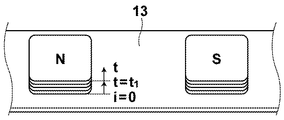
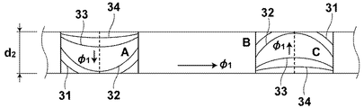
- FIG. 1B, FIG. 1C and FIG. 1D below show the temporal generation process of the equivalent plate magnet of the one-turn coil array of the rotor, the temporal process of magnetic flux penetration diffusion inside the soft magnetic metal plate of the metal load on the back, and The behavior and the like related to the constant ⁇ 2 are conceptually illustrated.
- FIG. 1B is a diagram illustrating a generation process of an equivalent plate magnet induced in the one-turn coil array.
- the magnetic flux ⁇ 1 flows as indicated by an arrow. For example, it is divided into A, B, and C blocks along the penetration direction of the Sin magnetic flux for one phase.
- the circumferential magnetic flux flowing through the block B is not involved in the generated torque at all and is merely a function as a magnetic path, and is excluded from the following examination.
- the B block with the Sin magnetic flux acts as an A or C block with respect to the Cos magnetic flux. Therefore, all the blocks have the function of inducing eddy currents by permeating and diffusing in the thickness direction, and the function as a simple magnetic path as described above, while changing constantly at the same time.
- the behavior of the magnetic metal plate only in the thickness direction and the influence of the peripheral speed V are considered simultaneously.
- FIG. 1D also shows a conceptual induction equivalent magnet having an N pole on the upper surface and an S pole on the lower surface.
- step response voltage 41 that makes it easy to understand transient phenomena from the power supply is applied to the stator winding
- the combined time constant ⁇ with the time constant ⁇ 0 of the stator winding is actually 4.83 ms, and this process is indicated by 45 in the figure.
- the time pattern of the eddy current path in the magnetic flux penetration diffusion process to the 2.0 mm thick soft magnetic metal plate (metal load) just below the back of the one-turn coil is, for example, closer to the surface, the eddy current Id becomes larger at the center.
- a circulation path of zero, and with the interior of the eddy current Id flux penetration, about 0.5Id eddy current two hours 0.1 ⁇ is after the diffusion time 0.3Tau 2 hours, tau in the 2 hours after about 0.3Id 3 ⁇ 2 hours later, it decreases gradually to about 0.05Id (as a one-dimensional problem).
- the total eddy current integrated with respect to the osmotic diffusion elapsed time is zero when the primary excitation current is 0 + time, and there is no osmotic diffusion wave, so the eddy current is also zero.
- the permeation diffusion is completely completed, a DC magnetic flux flows, and the eddy current generated in the magnetic flux permeation diffusion process and the accompanying eddy current resistance disappear.
- the synthesis time constant ⁇ 3 in the magnetic flux penetration diffusion process is 4.83 ms (0.5 ms + 4.33 ms).
- this eddy current resistance is a variable constant that changes as the current path changes. Therefore, it is understood that this is the behavior of eddy current within the transient phenomenon that is intensively expressed by this variable constant circuit.
- Current path that changes every moment inside the soft magnetic metal plate (this is a bowl-like shape in the thickness direction of the plate, and the height and thickness of its edge change every moment. The behavior of the total integration amount can be found by the search coil surrounding the center and edge of the plate.
- FIG. 6 shows a slow unimodality in the frequency characteristic of the secondary induced current for one phase with respect to the driving frequency of the power supply.
- td was obtained from the BH hysteresis method (area and its magnetic flux density) shown in FIG. .
- the eddy current reaches a maximum at approximately 0.7 ms after applying the primary excitation voltage of Step Function, and then gradually decreases to zero. Further, it was found that the eddy current from 0.1 to 0.2 times the sum tau 3 between the constant tau 1 time constant tau 0 and osmotic diffusion wave when the stator winding have time td to maximize. This shows the allowable range of Formula (1).
- the temporal pattern of the flux penetration diffusion wave that is, the temporal pattern of the eddy current shows a left-clogging shape (not shown).
- the disturbance of this pattern due to motion is that the strength of the induction equivalent magnet is left-clogged, which indicates a phase lag.
- FIG. 2 shows the above process qualitatively and lumpedly.
- a graph 41 indicates a primary excitation applied voltage (step response)
- a graph 42 indicates a primary excitation rectangular applied voltage (step response). 400Hz
- graph 44 shows the time response of the primary flux penetration diffusion wave to the rotor metal load (soft magnetic metal plate 14).
- the frequency fg of the power supply is determined so that the loop area of the BH hysteresis curve is maximized, where H is the strength of the magnetic field generated by the magnetism generating mechanism and B is the magnetic flux density of the rotating mechanism.
- H is the strength of the magnetic field generated by the magnetism generating mechanism
- B is the magnetic flux density of the rotating mechanism.
- the area of this BH hysteresis loop swells from the thin loop area to an egg shape as the frequency increases, and the loop area is maximized at a certain frequency, and then the left slope loop changes to a right slope loop as the frequency increases. Its area shrinks rapidly.
- the frequency f g of the power supply 15 at which the loop area of the BH hysteresis curve is maximized is determined.
- This frequency is determined by sweeping the power supply frequency and detecting the point where the loop area of the BH hysteresis curve is maximized.
- the loop area of the BH hysteresis curve is, for example, that the excitation current for one phase of the magnetic generation mechanism unit (corresponding to the magnetic field strength H) is set on the X axis of the oscilloscope.
- the Lissajous figure drawn on the oscilloscope is obtained by putting the AC current flowing in the soft magnetic metal plate on the back of the oscilloscope in the Y axis of the oscilloscope (integrated by detecting with the search coil) It can be obtained by determining the area of the Lissajous diagram. In this way, the frequency fg is determined. This also corresponds to four times the response time td until the eddy current due to the magnetic flux penetration diffusion wave to the soft magnetic metal plate reaches the maximum when the drive signal cycle Tg of the power supply is a voltage applied by the power supply.
- the BH-hysteresis loop area curve and the secondary (rotor) magnetic flux density curve are similar to the power supply frequency, suggesting that the maximum magnetic flux density may be the maximum loop area. Is done. At this time, it is performed in a non-power matching state.
- the resistance R1 is mainly studied. It is narrowed down to within 3dB.
- Z1 ⁇ R1 means that the influence of ⁇ sL1 is small enough to be ignored.
- n 2 Z3 ⁇ n 2 R3 means that the influence of ⁇ sL3 is small enough to be ignored.
- the resistance matching frequency is also 400 Hz.
- the energy converter of the present invention has an eddy current distribution pattern, of course, in which the period of maximum eddy current in the moving rotor circuit and the eddy current resistance at that time depend on the applied voltage and drive signal period. Since it is both speed-dependent and speed-dependent, it further includes a control unit that adjusts the rotation speed of the rotation mechanism unit having a predetermined magnetic gap length G so as to always become maximum.
- the alternating magnetic flux ( ⁇ 1 ) is generated by the surface current of the eddy current in the soft magnetic metal plate 14 on the back of the rotor. It becomes impossible to permeate and diffuse, and the function as a closed magnetic path material disappears except for the surface, resulting in an air-core state.
- this evaluation index can estimate the state with the magnetic Reynolds number Rm as 1 as a boundary, it is difficult to measure the magnetic Reynolds number, which is also an evaluation index of this moving rotor, and it was left as a future issue.
- the machine output can be maximized by performing power matching in the machine output.
- the load is not a dry load but a speed-dependent viscous load such as a fan
- the internal resistance of the mechanical output source in the resistance region and the resistance of the viscous load are equal in the mechanical output characteristics of the induction motor, Resistance matching is established on the machine output side, and the maximum machine output is the operating point.
- p is an electrical angle number.
- N, S pole pairs Number of N, S pole pairs.
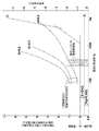
- FIG. 5 shows one end of a thermal rotor characteristic obtained simultaneously with heat and power in an unloaded state.
- the deterioration from the ideal no-load rotation speed is due to the increase in the iron loss of the rotor.
- the primary excitation angular frequency ⁇ s was 400 Hz
- the magnetic gap length G 7 mm
- the input voltage was 70 V
- a sharp secondary induced current 44A could be induced.
- the maximum was able to induce a secondary induced current of 70A.
- a rotating magnetic field for rotational driving and an alternating magnetic field for induction heating are simultaneously or selectively generated in a magnetic generating mechanism by a power source, and the rotor of the rotating mechanical unit performs rotational driving and induction. It is possible to perform the heating action independently and positively.
- the energy transmission performance from the magnetism generating mechanism unit to the rotating mechanism unit can be improved. For example, in the rotating mechanism unit even under a large magnetic gap length of about 10 mm. Enough energy output can be secured for home use.
- this detachable cordless thermal rotor housing that actively uses lossy eddy current without using rare metal magnets can be used as an underwater heat source and power source as a dishwashing function sink, Providing core technologies for next-generation kitchen systems such as the use of underwater movable chairs in the bathtub and the provision of a power source for mixers to the existing IH table and the leaf hidden ventilation fan under the floor.
- a thermal rotor housing with a planetary gear mechanism or a thick wound core type that obtains high torque through deceleration of the planetary gear mechanisms 17, 18, 19 of the rotating mechanism 2 in FIG. It is used in place of the power-driven rotor housing.
- This technology can also be applied to special flat induction motors (TANDEM) with a resulting magnetic gap (double magnetic gap length), such as the flat 2Rotors and 1Stator.
- TENDEM stack configuration multi-TANDEM can be used for propulsion power sources for small vehicles, agricultural equipment, and bicycles.
- the magnetic properties of the rotor that can withstand high temperatures close to 300 ° C, together with its separation function, provide a power source that can be used in a special environment in a high-temperature furnace.
- the flat thermal dynamic rotor can naturally be transformed into a cylindrical shape.
- a hollow cylindrical rotor configuration is a feature. Water and air can be guided to the hollow cylindrical rotor, and heat and rotational thrust can be applied simultaneously. For example, circulating hot water in a 24-hour bath is led to a thermal dynamic rotor of a hollow cylinder, and a power source for circulation is obtained while heating.
- the energy converter according to the present invention is significantly different from the existing state, and it is effective to reduce the copper loss of the winding of the magnetism generation mechanism as much as possible (in this prototype, about 0.5 ⁇ / interference) and to the rotor heat source. Changing to use greatly contributes to improving efficiency.
- the device ratings are defined separately for the magnetism generating mechanism and the rotating mechanism, and the overall rating is determined.
- the structure of the energy converter of the present invention described above is based on the operation and application of a flat structure induction motor in which the stator and rotor can be separated, but it can be applied to an integral structure or a cylindrical type.
- FIGS. 1-10 Data relating to the induction motor of the present invention is shown in FIGS.
Landscapes
- Engineering & Computer Science (AREA)
- Power Engineering (AREA)
- Physics & Mathematics (AREA)
- Electromagnetism (AREA)
- Manufacturing & Machinery (AREA)
- Induction Machinery (AREA)
- Connection Of Motors, Electrical Generators, Mechanical Devices, And The Like (AREA)
- Iron Core Of Rotating Electric Machines (AREA)
- Dynamo-Electric Clutches, Dynamo-Electric Brakes (AREA)
- General Induction Heating (AREA)
Abstract
Description




2 回転機構部
13 1巻コイル列円盤(1巻コイル列板)
14 軟磁性金属板
15 インバータ回路(電源)
G 磁気的空隙
Claims (9)
- 交流電源に接続されて磁界を発生する磁気発生機構部と、複数の1巻コイルが一定間隔をおいて配列されてなる1巻コイル列部材と該1巻コイル列部材の前記磁気発生機構部側と反対側に配された軟磁性金属板材とを有し、所定の磁気的空隙を隔てて前記磁気発生機構部と前記1巻コイル列部材とが対向するように構成され、前記磁界により回転駆動される回転機構部とを備えたエネルギー変換器であって、
前記電源の駆動信号周期が、前記軟磁性金属板材の内部に生成される渦電流を最大とするものであることを特徴とするエネルギ-変換器。 - 前記電源の駆動信号周期Tgが、下記式(1)の条件を満たすことを特徴とする請求項1記載のエネルギー変換器。

- 前記電源の駆動信号周期Tgにおいて、前記磁気的空隙を整合面とした下記式(2)の抵抗整合条件を満たすことを特徴とする請求項2記載のエネルギー変換器。

- 前記電源の駆動信号周期Tgが、前記磁気発生機構部の磁界の強さHと前記回転機構部の誘導磁束密度Bが作るB-Hヒステリシス ループの面積を最大とするものであることを特徴とする請求項1記載のエネルギー変換器。
- 前記電源の駆動信号周期Tgにおいて、前記磁気的空隙を整合面とした下記式(2)の抵抗整合条件を満たすことを特徴とする請求項4記載のエネルギー変換器。

- 前記回転機構部が、遊星歯車機構を内在するものであることを特徴とする請求項1から5のいずれか1項記載のエネルギー変換器。
- 前記回転機構部の機械回転数が最大になるように前記電源の駆動信周期Tg及び印加電圧を調整する制御手段をさらに備えたことを特徴とする請求項1から6のいずれか1項記載のエネルギー変換器。
- 前記磁気発生機構部が、コイルが円形状に配置されてなる扁平型磁気発生機構部であり、
前記1巻コイル列部材および前記軟磁性金属板材が、扁平形状ないし円板状の構造を有するものであることを特徴とする請求項1から7のいずれか1項記載のエネルギ-変換器。 - 前記磁気発生機構部が、筒状構造を有するものであり、前記回転機構部の、
前記1巻コイル列部材が、かご型構造を有するものであり、
前記軟磁性金属板材が、中空円筒状であることを特徴とする請求項1から7のいずれか1項記載のエネルギー変換器。
Priority Applications (3)
| Application Number | Priority Date | Filing Date | Title |
|---|---|---|---|
| CN200980155178.0A CN102292909B (zh) | 2008-11-26 | 2009-11-26 | 能量转换器 |
| US13/131,306 US8575878B2 (en) | 2008-11-26 | 2009-11-26 | Energy converter |
| EP09828868.1A EP2355335A4 (en) | 2008-11-26 | 2009-11-26 | ENERGY CONVERTER |
Applications Claiming Priority (2)
| Application Number | Priority Date | Filing Date | Title |
|---|---|---|---|
| JP2008300287 | 2008-11-26 | ||
| JP2008-300287 | 2008-11-26 |
Publications (1)
| Publication Number | Publication Date |
|---|---|
| WO2010061618A1 true WO2010061618A1 (ja) | 2010-06-03 |
Family
ID=42225503
Family Applications (1)
| Application Number | Title | Priority Date | Filing Date |
|---|---|---|---|
| PCT/JP2009/006409 Ceased WO2010061618A1 (ja) | 2008-11-26 | 2009-11-26 | エネルギー変換器 |
Country Status (5)
| Country | Link |
|---|---|
| US (1) | US8575878B2 (ja) |
| EP (1) | EP2355335A4 (ja) |
| JP (2) | JP4727746B2 (ja) |
| CN (1) | CN102292909B (ja) |
| WO (1) | WO2010061618A1 (ja) |
Cited By (1)
| Publication number | Priority date | Publication date | Assignee | Title |
|---|---|---|---|---|
| WO2014083833A1 (ja) * | 2012-11-29 | 2014-06-05 | 株式会社Tbk | 暖房送風機及び車両 |
Families Citing this family (3)
| Publication number | Priority date | Publication date | Assignee | Title |
|---|---|---|---|---|
| JP2012245871A (ja) * | 2011-05-27 | 2012-12-13 | Tbk:Kk | 電気式暖房装置および電気自動車 |
| RU170077U1 (ru) * | 2016-02-02 | 2017-04-13 | Евгений Николаевич Коптяев | Обратимый преобразователь |
| GB2556267A (en) * | 2016-02-10 | 2018-05-23 | Rotaheat Ltd | Heat generator |
Citations (7)
| Publication number | Priority date | Publication date | Assignee | Title |
|---|---|---|---|---|
| JPH10108426A (ja) * | 1996-10-01 | 1998-04-24 | Namiki Precision Jewel Co Ltd | 交流エネルギー変換駆動機器 |
| JPH11127559A (ja) * | 1997-10-22 | 1999-05-11 | Namiki Precision Jewel Co Ltd | 交流エネルギー変換機 |
| JPH11332186A (ja) * | 1998-05-12 | 1999-11-30 | Namiki Precision Jewel Co Ltd | 交流エネルギー変換機 |
| JP2001057762A (ja) * | 1999-06-08 | 2001-02-27 | Tetsuo Sekiya | 電動機 |
| JP2001069734A (ja) | 1999-06-24 | 2001-03-16 | Tetsuo Sekiya | 電気エネルギ変換器 |
| JP2002272022A (ja) * | 2001-03-08 | 2002-09-20 | Mitsubishi Electric Corp | 電動機 |
| JP2002345229A (ja) * | 2001-05-17 | 2002-11-29 | Shinko Electric Co Ltd | 加力装置、加力方法、搬送装置および搬送方法 |
Family Cites Families (9)
| Publication number | Priority date | Publication date | Assignee | Title |
|---|---|---|---|---|
| US3668448A (en) * | 1967-05-29 | 1972-06-06 | Enakichi Hayasaka | Homopole type ac generator |
| JPS57131875A (en) * | 1981-02-09 | 1982-08-14 | Hitachi Ltd | Energy converting device |
| FR2514966B1 (fr) * | 1981-10-16 | 1987-04-24 | Materiel Magnetique | Convertisseur d'energie cinetique de rotation en chaleur par generation de courants de foucault |
| US4663536A (en) * | 1985-03-04 | 1987-05-05 | Precise Power Corporation | A.C. motor-generator |
| JP4007339B2 (ja) * | 2003-11-07 | 2007-11-14 | 株式会社デンソー | 交流モータとその制御装置 |
| US7777600B2 (en) * | 2004-05-20 | 2010-08-17 | Powerpath Technologies Llc | Eddy current inductive drive electromechanical liner actuator and switching arrangement |
| CN100486393C (zh) | 2005-02-07 | 2009-05-06 | 杨家华 | 工频电加热的方法及其装置 |
| US7463914B2 (en) * | 2005-06-08 | 2008-12-09 | Dynamo Capital, Inc. | Superconducting acyclic homopolar electromechanical power converter |
| US7420287B2 (en) * | 2006-03-28 | 2008-09-02 | Aleksandr Smushkovich | Intermittent force powered electromagnetic converters especially for sea waves |
-
2009
- 2009-11-26 EP EP09828868.1A patent/EP2355335A4/en not_active Withdrawn
- 2009-11-26 JP JP2009268612A patent/JP4727746B2/ja not_active Expired - Fee Related
- 2009-11-26 US US13/131,306 patent/US8575878B2/en not_active Expired - Fee Related
- 2009-11-26 CN CN200980155178.0A patent/CN102292909B/zh not_active Expired - Fee Related
- 2009-11-26 WO PCT/JP2009/006409 patent/WO2010061618A1/ja not_active Ceased
-
2011
- 2011-04-12 JP JP2011088090A patent/JP2011167065A/ja not_active Withdrawn
Patent Citations (7)
| Publication number | Priority date | Publication date | Assignee | Title |
|---|---|---|---|---|
| JPH10108426A (ja) * | 1996-10-01 | 1998-04-24 | Namiki Precision Jewel Co Ltd | 交流エネルギー変換駆動機器 |
| JPH11127559A (ja) * | 1997-10-22 | 1999-05-11 | Namiki Precision Jewel Co Ltd | 交流エネルギー変換機 |
| JPH11332186A (ja) * | 1998-05-12 | 1999-11-30 | Namiki Precision Jewel Co Ltd | 交流エネルギー変換機 |
| JP2001057762A (ja) * | 1999-06-08 | 2001-02-27 | Tetsuo Sekiya | 電動機 |
| JP2001069734A (ja) | 1999-06-24 | 2001-03-16 | Tetsuo Sekiya | 電気エネルギ変換器 |
| JP2002272022A (ja) * | 2001-03-08 | 2002-09-20 | Mitsubishi Electric Corp | 電動機 |
| JP2002345229A (ja) * | 2001-05-17 | 2002-11-29 | Shinko Electric Co Ltd | 加力装置、加力方法、搬送装置および搬送方法 |
Non-Patent Citations (1)
| Title |
|---|
| See also references of EP2355335A4 * |
Cited By (1)
| Publication number | Priority date | Publication date | Assignee | Title |
|---|---|---|---|---|
| WO2014083833A1 (ja) * | 2012-11-29 | 2014-06-05 | 株式会社Tbk | 暖房送風機及び車両 |
Also Published As
| Publication number | Publication date |
|---|---|
| JP2010154737A (ja) | 2010-07-08 |
| US20110248664A1 (en) | 2011-10-13 |
| JP2011167065A (ja) | 2011-08-25 |
| CN102292909B (zh) | 2014-03-26 |
| EP2355335A1 (en) | 2011-08-10 |
| JP4727746B2 (ja) | 2011-07-20 |
| EP2355335A4 (en) | 2015-11-25 |
| CN102292909A (zh) | 2011-12-21 |
| US8575878B2 (en) | 2013-11-05 |
Similar Documents
| Publication | Publication Date | Title |
|---|---|---|
| CN103490573B (zh) | 一种轴向磁场磁通切换型表贴式永磁记忆电机 | |
| CN103715848B (zh) | 一种轴向磁场定子分割式磁通切换型记忆电机 | |
| KR20150048075A (ko) | 낮은 온도에서 페라이트 자석 모터를 가열하기 위한 시스템 및 방법 | |
| CN103151859A (zh) | 一种磁通切换型表贴式永磁记忆电机 | |
| Zhu et al. | A novel axial flux magnetically geared machine for power split application | |
| JP4727746B2 (ja) | エネルギー変換器 | |
| JP2010154737A5 (ja) | ||
| CN110115104B (zh) | 具有直流励磁装置的转动感应加热器 | |
| Ye et al. | Development and analysis of a novel cascaded brushless self-excited air-core compensated pulsed alternator with squirrel-cage rotor winding | |
| MXPA05003231A (es) | Dispositivo de calentamiento magnetico. | |
| JP7345496B2 (ja) | 直流励磁、極めて小さな電気的/動力学的効率、及び極めて高い熱copを有する回転式誘導熱発生器 | |
| US5347107A (en) | Low frequency electromagnetic induction heater with magnetic flux diffusing members | |
| US20060118547A1 (en) | Frying hob arrangement | |
| CN102843012B (zh) | 拨动式节能型电动机 | |
| Flankl et al. | Energy harvesting with single-sided linear induction machines featuring secondary conductive coating | |
| KR20110103637A (ko) | 자석을 이용한 유도 발열장치 | |
| US5401939A (en) | Electromagnetic induction heater with magnetic flux diffusing members | |
| RU65335U1 (ru) | Теплогенерирующий электромеханический преобразователь | |
| KR20100068616A (ko) | 고효율용 쌍코어 구조 | |
| US1797519A (en) | Electric heater | |
| CN103041740A (zh) | 电磁加热式电磁铁直接驱动磁力搅拌器 | |
| RU2313884C2 (ru) | Электрическая машина (варианты) | |
| Kurihara et al. | Single-phase line-start permanent-magnet motors with start-up and synchronization capabilities under full-load torque | |
| RU2451430C1 (ru) | Устройство для нагрева и транспортирования жидкой среды | |
| RU46139U1 (ru) | Теплогенерирующий электромеханический преобразователь |
Legal Events
| Date | Code | Title | Description |
|---|---|---|---|
| WWE | Wipo information: entry into national phase |
Ref document number: 200980155178.0 Country of ref document: CN |
|
| 121 | Ep: the epo has been informed by wipo that ep was designated in this application |
Ref document number: 09828868 Country of ref document: EP Kind code of ref document: A1 |
|
| NENP | Non-entry into the national phase |
Ref country code: DE |
|
| REEP | Request for entry into the european phase |
Ref document number: 2009828868 Country of ref document: EP |
|
| WWE | Wipo information: entry into national phase |
Ref document number: 2009828868 Country of ref document: EP |
|
| WWE | Wipo information: entry into national phase |
Ref document number: 13131306 Country of ref document: US |