WO2010064591A1 - パイプ切断機及びパイプの切断方法 - Google Patents
パイプ切断機及びパイプの切断方法 Download PDFInfo
- Publication number
- WO2010064591A1 WO2010064591A1 PCT/JP2009/070089 JP2009070089W WO2010064591A1 WO 2010064591 A1 WO2010064591 A1 WO 2010064591A1 JP 2009070089 W JP2009070089 W JP 2009070089W WO 2010064591 A1 WO2010064591 A1 WO 2010064591A1
- Authority
- WO
- WIPO (PCT)
- Prior art keywords
- pipe
- cutting
- breaking
- rotary cutter
- cutter blade
- Prior art date
- Legal status (The legal status is an assumption and is not a legal conclusion. Google has not performed a legal analysis and makes no representation as to the accuracy of the status listed.)
- Ceased
Links
Images


Classifications
-
- B—PERFORMING OPERATIONS; TRANSPORTING
- B23—MACHINE TOOLS; METAL-WORKING NOT OTHERWISE PROVIDED FOR
- B23D—PLANING; SLOTTING; SHEARING; BROACHING; SAWING; FILING; SCRAPING; LIKE OPERATIONS FOR WORKING METAL BY REMOVING MATERIAL, NOT OTHERWISE PROVIDED FOR
- B23D31/00—Shearing machines or shearing devices covered by none or more than one of the groups B23D15/00 - B23D29/00; Combinations of shearing machines
- B23D31/002—Breaking machines, i.e. pre-cutting and subsequent breaking
-
- B—PERFORMING OPERATIONS; TRANSPORTING
- B23—MACHINE TOOLS; METAL-WORKING NOT OTHERWISE PROVIDED FOR
- B23D—PLANING; SLOTTING; SHEARING; BROACHING; SAWING; FILING; SCRAPING; LIKE OPERATIONS FOR WORKING METAL BY REMOVING MATERIAL, NOT OTHERWISE PROVIDED FOR
- B23D21/00—Machines or devices for shearing or cutting tubes
Definitions
- the present invention relates to a pipe cutting machine, a pipe cutting method, and a method for manufacturing a photosensitive drum substrate.
- the present invention has been made in view of the above-described technical background.
- the purpose of the present invention is to efficiently cut a pipe when the pipe is cut into a plurality of pieces, and to prevent generation of chips.
- An object of the present invention is to provide a pipe cutting machine, a pipe cutting method, and a method for manufacturing a photosensitive drum substrate. Other objects and advantages of the present invention will become apparent from the following preferred embodiments.
- the present invention provides the following means.
- a cutting device having a rotary cutter blade that forms a cutting portion for breaking on an outer surface of a pipe; A breaking device that is disposed at a position away from the cutting device in the direction of the distal end of the pipe, and breaks the breaking cut portion of the pipe; A feed device for advancing the pipe in the direction of its distal end and feeding the breaking cut portion of the pipe from the cutting device to the breaking device; While the breaking cutter is formed on the outer surface of the pipe by the rotary cutter blade of the cutting device, the breaking portion of the pipe sent from the cutting device to the breaking device is broken by the breaking device.
- Pipe cutting machine characterized by
- a rupture resistance measuring device for measuring a rupture resistance force when the rupture device breaks the rupture cut portion of the pipe;
- a first cutting amount control device that controls a cutting amount to an outer surface of a pipe by a rotary cutter blade of the cutting device based on the breaking resistance force measured by the breaking resistance force measuring device;
- the pipe cutting machine according to 1 or 2.
- the first cut amount control device according to the above item 3, wherein the first cutting amount control device is configured to notify abnormality information or / and stop cutting the pipe when the breaking resistance is out of a predetermined range. Pipe cutting machine.
- a cutting resistance measuring device for measuring a cutting resistance force when forming the cutting portion for breaking on the outer surface of the pipe by the rotary cutter blade of the cutting device;
- a second cutting amount control device that controls a cutting amount to the outer surface of the pipe by the rotary cutter blade of the cutting device based on the cutting resistance force measured by the cutting resistance force measuring device.
- the pipe cutting machine according to any one of 1 to 4.
- the second cutting amount control device when the cutting resistance is deviated from a predetermined range, the cutting resistance is continuously deviated from the predetermined range a plurality of times, and the continuous number is equal to or more than the predetermined number.
- the continuous number is a predetermined number or more.
- a clamping device for clamping the pipe includes a clamp member having a clamp surface that comes into contact with an outer surface of a pipe, and a holding member that detachably holds the clamp member,
- the holding member is provided with a dovetail groove-shaped recess
- the clamp member is provided with a convex strip corresponding to the concave strip,
- the ridge portion of the clamp member is slidably inserted into the recess portion of the holding member so as to be detachable, and the clamp member is detachably held by the holding member,
- the convex strip portion is pushed in the lateral direction, thereby fixing the position of the convex strip portion with respect to the depth direction of the concave strip portion.
- the pipe cutting method is characterized in that the breaking cut portion of the pipe advanced in the tip direction of the pipe is broken while forming a new breaking cut portion on the outer surface of the pipe with a rotary cutter blade.
- a method for producing a photosensitive drum substrate by cutting a raw tube into a predetermined length 22.
- the present invention has the following effects.
- the breaking device in the pipe cutting machine, is arranged at a position away from the cutting device in the direction of the tip of the pipe, and the cutting portion for breaking is formed on the outer surface of the pipe by the rotary cutter blade of the cutting device.
- the breaking part of the pipe sent from the cutting device to the breaking device is broken by the breaking device. Therefore, it is possible to simultaneously perform a cutting step for forming a cut portion on the outer surface of the pipe and a breaking step for breaking the cut portion of the pipe. Thereby, the pipe can be cut efficiently.
- this pipe cutting machine includes not only a device for cutting a pipe with a saw blade but also a cutting device having a rotary cutter blade and a breaking device, generation of chips can be prevented.
- the cutting device has a plurality of rotary cutter blades arranged side by side in the circumferential direction of the pipe, and a plurality of rotary cutter blades are used to form a breaking cut portion on the outer surface of the pipe.
- the breaking cut portion can be rapidly formed on the outer surface of the pipe, that is, the breaking cut portion can be efficiently formed.
- the passage trajectory lines of the plurality of rotary cutter blades on the outer surface of the pipe are the pipes. If it is slightly displaced in the axial direction, there is a disadvantage that fine thread-like chips are generated.
- the quality of the pipe cut product can be stabilized by controlling the cut amount to the outer surface of the pipe by the rotary cutter blade of the cut device by the first cut amount control device.
- the operator can be notified of abnormal information related to the quality of the cut pipe product, and / or the cutting of the pipe can be stopped.
- the quality of the pipe cut product can be reliably stabilized by controlling the cut amount of the rotary cutter blade of the cutting device to the outer surface of the pipe by the second cutting amount control device.
- the cutting device and the breaking device are arranged so that the distance between the cutting device and the breaking device can be changed, the cutting device according to the length of the desired pipe cut product The distance to the breaking device can be changed. That is, the pipe can be cut into various lengths.
- the clamp member of the clamp device is detachably held by the holding member. Therefore, the clamp member can be exchanged according to the diameter of the pipe.
- the inventions [12] to [18] have the same effects as the inventions [1] to [7], respectively.
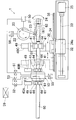
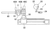
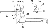
- FIG. 1 is a schematic side view of a pipe cutting machine according to an embodiment of the present invention.
- FIG. 2A is a side view of a state before the pipe is cut by the pipe cutting machine.
- FIG. 2B is a side view of a state where the pipe is conveyed to the cutting device of the pipe cutting machine.
- FIG. 2C is a side view showing a state in which the pipe is clamped by the both-side input / output clamping device of the cutting device of the pipe cutting machine.
- FIG. 2D is a side view of a state in the middle of forming the breaking cut portion on the outer surface of the pipe by the rotary cutter blade of the cutting device of the pipe cutting machine.
- FIG. 2A is a side view of a state before the pipe is cut by the pipe cutting machine.
- FIG. 2B is a side view of a state where the pipe is conveyed to the cutting device of the pipe cutting machine.
- FIG. 2C is a side view showing a state in which the pipe is clamp
- FIG. 2E is a side view of a state in which the pipe is clamped by the clamp device of the feeding device of the pipe cutting machine.
- FIG. 2F is a side view of a state in which the clamp of the pipe is released by both clamp devices of the cutting device of the pipe cutting machine.
- FIG. 2G is a side view of a state in which the pipe is advanced in the distal direction by the feeding device of the pipe cutting machine.
- FIG. 2H is a side view of a state in which the cutting portion for breaking the pipe is fed to the breaking device by the feeding device of the pipe cutting machine.
- FIG. 2I is a side view of a state in which the pipe is clamped by both front and rear clamping devices of the cutting device of the pipe cutting machine.
- FIG. 2J is a side view of a state in which the breaking notch of the pipe is being broken by the breaking device while the breaking notch is formed on the outer surface of the pipe by the rotary cutter blade of the pipe cutting machine.
- FIG. 2K is a side view of a state in which the notch for breaking the pipe is broken by the breaking device of the pipe cutting machine.
- FIG. 2L is a side view of the pipe cutting machine with the feeding device moved to the original position.
- FIG. 2M is a side view of a state in which the pipe is cut to its proximal end by the pipe cutting machine.
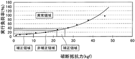
- FIG. 3 shows the relationship between the effective load factor of the servo motor when the breaking notch of the sample pipe is broken by the breaking device and the breaking resistance when the breaking notch of the sample pipe is broken by the breaking test machine. It is a figure (graph) shown.
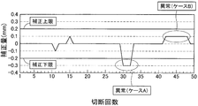
- FIG. 4 is a diagram (graph) showing the relationship between the number of cuttings and the correction amount of the cutting amount.
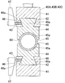
- FIG. 5 is a cross-sectional view of the clamping device of the pipe cutting machine.
- FIG. 6 is a cross-sectional view of a replacement clamp member used in the clamp device.
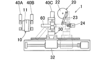
- FIG. 1 is a schematic side view of a pipe cutting machine for explaining the configuration of the pipe cutting machine according to an embodiment of the present invention.
- This pipe cutting machine 1 cuts a long pipe 60 into a plurality of fixed lengths to a predetermined length.
- the pipe 60 is made of, for example, a drawn round pipe.
- the pipe 60 is, for example, a base pipe for a photosensitive drum base. Therefore, the pipe cut product 62 obtained by cutting the pipe 60 into a predetermined length by the pipe cutting method using the pipe cutting machine 1 is used for the photosensitive drum base.
- the photosensitive drum substrate is used in, for example, an electrophotographic apparatus (copying machine, laser beam printer, etc.), and a predetermined film such as an OPC (organic photoconductor) film is applied to the outer surface thereof. For this reason, the cut pipe 62 is required to have no chips on its outer surface, no burrs at the cut portion, high roundness, and the like.
- the material of the pipe 60 is a metal such as aluminum (including its alloy).
- the cross-sectional shape of the pipe 60 is an annular shape.
- the outer diameter of the pipe 60 is, for example, 24 to 30 mm
- the thickness of the pipe 60 is, for example, 0.5 to 1 mm
- the length of the pipe 60 is, for example, 6000 to 8000 mm.
- the cutting length of the pipe 60 by the pipe cutting machine 1 (that is, the length of the pipe cutting product 62) is, for example, 246 to 357 mm.
- the outer diameter, the thickness, the length, and the cutting length of the pipe 60 are not limited to the above ranges, but are set according to the application.
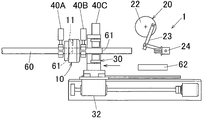
- the pipe cutting machine 1 includes a cutting device 10, a breaking device 20, a feeding device 30, a breaking resistance measuring device 50, a first cutting amount control device 51, a cutting resistance measuring device 52, and a second cutting.
- a quantity control device 53, a main control device 59, and the like are provided. The configuration of each device will be described below.
- the cutting device 10 has a disk-shaped rotary cutter blade 11.
- the rotary cutter blade 11 is configured to form a breaking cut 61 in an annular shape on the outer surface of a horizontally arranged pipe 60 over the entire circumference in the circumferential direction.
- a cutting edge is formed on the outer peripheral edge of the rotary cutter blade 11 over the entire circumference.
- the number of rotary cutter blades 11 is one or more. In the present embodiment, the number of rotary cutter blades 11 is only one. If there are a plurality of rotary cutter blades 11 (for example, 2 to 3), the plurality of rotary cutter blades 11 are spaced around the pipe 60 in the circumferential direction of the pipe 60. Arranged side by side.
- the rotary cutter blade 11 is capable of rotating and rotating, and is disposed so as to be able to revolve around the pipe 60 around the pipe 60 and to move in the radial direction of the pipe 60.
- the cutting device 10 then pushes the rotary cutter blade 11 around the pipe 60 with the blade 60 of the rotary cutter blade 11 pressed against the outer surface of the pipe 60 with a predetermined pressing force toward the central axis of the pipe 60.
- a breaking cut portion 61 is formed on the outer surface of the pipe 60 in an annular shape over the entire circumference thereof.
- the cut amount of the breaking cut portion 61 is changed by changing the amount of movement of the rotary cutter blade 11 in the pipe radial direction by a first cut amount control device 51 and a second cut amount control device 53 described later.
- the cutting device 10 is provided with an entry side clamp device 40A and an exit side clamp device 40B arranged in the vicinity of the entry side and the exit side of the rotary cutter blade 11, respectively.
- Each of the clamp devices 40A and 40B clamps and holds the pipe 60 so as to be detachable, and further clamps and holds the pipe 60 so that it cannot rotate about its axis and cannot move in the axial direction. Both clamp devices 40A and 40B have the same configuration. About the structure of both clamp apparatus 40A, 40B, the structure of 40 A of entrance side clamp apparatuses is demonstrated below on behalf of both.
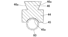
- the clamp device 40A is provided with an operation control unit 49 that controls the operation of the clamp device 40A. Furthermore, as shown in FIG. 5, the clamp device 40 ⁇ / b> A includes a pair of upper and lower clamp members 44, 44 having clamp surfaces 45, 45 that abut against the outer surface of the pipe 60, and each clamp member 44. And a pair of holding members 41, 41 for holding the detachable.
- the clamp surface 45 of each clamp member 44 is formed with a concave portion 45 a having an arcuate cross section that fits to the outer surface of the pipe 60.
- Each dovetail member 42 has a dovetail groove 42.
- Each clamp member 44 is integrally provided with a protrusion 46 corresponding to the recess 42. And the convex strip part 46 of the clamp member 44 is slidably inserted in the concave strip part 42 of the holding member 41 so that the clamp member 44 is detachably attached to the holding member 41 and held. The member 41 is held so as not to drop off.
- the holding member 41 is provided with a screw hole 43 that communicates the outer side surface thereof with the inclined inner side surface of the concave portion 42, and a push bolt 48 of the clamp lever 47 is screwed into the screw hole 43.
- a push bolt 48 of the clamp lever 47 is screwed into the screw hole 43.
- the tip of the push bolt 48 appears and disappears in the lateral direction with respect to the recess 42.
- the inclined side surface 46 a of the convex strip 46 is the tip of the push bolt 48 of the clamp lever 47 under the state where the convex strip 46 of the clamp member 44 is inserted into the concave strip 42 of the holding member 41.
- the ridge 46 is slightly moved in the depth direction of the recess 42, and the clamp member 44 is in close contact with the holding member 41, thereby the depth of the recess 42.
- the position of the ridge 46 with respect to the direction is fixed.
- the pushing of the inclined side surface 46a of the ridge 46 with the tip of the push bolt 48 of the clamp lever 47 is stopped, the fixing of the position of the ridge 46 is released. In this way, the clamp member 44 is held by the holding member 41.
- the clamp member 44 can be replaced according to the diameter of the pipe 60.
- a concave portion 45 a having an arcuate cross section that fits to the outer surface of the small-diameter pipe 60 is formed on the clamp surface 45.
- the replacement method of the clamp member 44 is as follows. That is, after stopping pushing the inclined side surface 46a of the ridge 46 with the tip of the push bolt 48 of the clamp lever 47, the ridge 46 is slid out of the ridge 42, thereby clamping the clamp member. 44 is removed from the holding member 41.
- the protrusion 46 of the replacement clamp member 44 is slid into the recess 42 of the holding member 41, and the inclined side surface 46 a of the protrusion 46 is laterally moved by the tip of the push bolt 48 of the clamp lever 47.
- the clamp member 44 can be exchanged by such a procedure.
- the breaking device 20 breaks the breaking cut portion 61 of the pipe 60 formed by the rotary cutter blade 11 of the cutting device 10, thereby leading the tip of the breaking cut portion 61 of the pipe 60.
- the side portion 62 (that is, a pipe cut product) is cut (divided) from the pipe 60 (specifically, a pipe main body).
- the breaking device 20 is arranged at a position away from the cutting device 10 in the distal direction (downstream direction) of the pipe 60, and is configured to break the breaking cutting portion 61 of the pipe 60 by the driving force of the servo motor 21. Has been.
- the breaking device 20 includes a rotating plate 22 that is driven to rotate by a servo motor 21, a chuck member 24 that holds the tip of the pipe 60 by being fitted in the tip of the pipe 60, and the rotating plate 22 and the chuck member 24. And a link mechanism 23 connected to each other.
- the breaking device 20 is configured such that when the rotating plate 22 is rotated, the rotating operation of the rotating plate 22 is transmitted to the chuck member 24 through the link mechanism 23 as a vertical swing operation. Therefore, in the breaking device 20, when the rotating plate 22 is rotated with the tip end portion of the pipe 60 held by the chuck member 24, the chuck member 24 swings up and down, thereby causing the breaking cut portion of the pipe 60.
- the breaking device 20 is of a type that breaks the breaking notch 61 of the pipe 60 by bending the portion 62 on the tip side of the breaking notch 61 of the pipe 60 from the breaking notch 61. That is, a bending fracture device.
- the pipe cutting machine 1 is sent from the cutting device 10 to the breaking device 20 by the feeding device 30 while forming a new cutting portion 61 for breaking on the outer surface of the pipe 60 by the rotary cutter blade 11 of the cutting device 10.
- the breaking cut portion 61 of the pipe 60 that has been cut is configured to be broken by the breaking device 20.
- the feeding device 30 is configured to advance the pipe 60 in the distal direction and feed the breaking cut portion 61 of the pipe 60 from the cutting device 10 to the breaking device 20 on a regular scale.
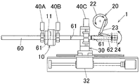
- the feeding device 30 includes a clamping device 40C that clamps and holds the pipe 60, and a moving mechanism 32 that reciprocally moves the clamping device 40C between the cutting device 10 and the breaking device 20.
- the configuration of the clamping device 40C is the same as the clamping devices 40A and 40B of the cutting device 10 described above.
- the moving mechanism 32 includes a screw rod 33 having a screw formed on its outer peripheral surface over its entire length, a stage base 34 having a screw hole 34a meshing with the screw rod 33, a drive source 35 that rotationally drives the screw rod 33, and Guide rail 36 is provided.
- the screw rod 33 is arranged in parallel with the feeding direction of the pipe 60.
- the drive source 35 is composed of a servo motor, and is provided at one end of the screw rod 33.
- the stage base 34 is moved between the cutting device 10 and the breaking device 20 when the screw rod 33 screwed into the screw hole 34a is rotationally driven by the drive source 35.
- a clamping device 40C is installed in a fixed state.
- the guide rail 36 guides the stage base 34 so as to move in a predetermined direction.
- the pipe cutting machine 1 includes an auxiliary feeding device (not shown) that is arranged on the upstream side of the cutting device 10 and that sends the pipe 60 from the upstream side of the cutting device 10 to the cutting device 10.
- an auxiliary feeding device (not shown) that is arranged on the upstream side of the cutting device 10 and that sends the pipe 60 from the upstream side of the cutting device 10 to the cutting device 10.
- the pipe cutting machine 1 is configured such that the distance between the cutting device 10 and the breaking device 20 can be changed by a distance changing mechanism (not shown).
- the configuration of this changing mechanism is as follows.
- At least one of the cutting device 10 and the breaking device 20 is disposed so as to be movable in parallel with the tip direction of the pipe 60 (that is, the feeding direction of the cutting portion 61 for breaking the pipe 60 by the feeding device 30).
- the cutting device 10 and the breaking device 20 are arranged movably along a guide rail (not shown) or the like in parallel with the distal end direction of the pipe 60 independently of each other.
- the cutting device 10 is connected to a driving source (for example, a servo motor) 55 for moving the cutting device 10 in parallel with the tip direction of the pipe 60, and the breaking device 20 is connected to the tip direction of the pipe 60.
- a moving drive source (eg, servo motor) 56 that is moved in parallel with the motor is connected.
- the distance between the cutting device 10 and the breaking device 20 is changed by operating at least one of the moving drive source 55 of the cutting device 10 and the moving drive source 56 of the breaking device 20. Has been made.
- the distance between the cutting device 10 and the breaking device 20 may be changed manually, or the distance may be automatically changed.
- only one of the cutting device 10 and the breaking device 20 may be arranged so as to be movable in parallel with the distal end direction of the pipe 60.
- the breaking resistance measuring device 50 measures the breaking resistance when the breaking device 20 breaks the breaking notch 61 of the pipe 60 and is connected to the breaking device 20.
- the first cut amount control device 51 controls the cut amount to the outer surface of the pipe 60 by the rotary cutter blade 11 of the cut device 10 based on the break resistance force measured by the break resistance force measuring device 50. , Connected to the cutting device 10. Further, the first cutting amount control device 51 and the breaking resistance measuring device 50 are connected to each other via a control signal line.
- the first cutting amount control device 51 immediately notifies the abnormality information when the fracture resistance is out of a predetermined range (that is, a preset range) or / and the pipe 60 by the pipe cutting machine 1. It is supposed to immediately stop cutting.
- the abnormality information is, for example, notified by a speaker of a sound or sound (eg, an abnormal alarm sound) that a disconnection abnormality has occurred, by a lighting or blinking of a lamp indicating the occurrence of a disconnection abnormality, or / And it is notified by displaying abnormality information with a character, a figure, etc. on display devices, such as a display.
- the first cutting amount control device 51 causes the pipe cutting machine 1 (more specifically, the cutting device 10, the breaking device 20, the feeding device 30, etc.) to stop its operation. To stop the cutting of the pipe 60.
- the measurement of the breaking resistance force by the breaking resistance measuring device 50 and the control of the cutting amount by the first cutting amount control device 51 are specifically performed as follows.
- an execution load factor of the servo motor 21 for driving the breaking device when the breaking portion of the sample pipe is broken by the breaking device 20 Then, the relationship with the rupture resistance force when the rupture cut portion of the sample pipe is ruptured by a rupture tester capable of measuring the rupture resistance force is examined in advance.
- the quality of the cut product of each sample pipe broken by the break test machine is examined, and when the quality of the cut product is good, the range of resistance to break and the range of depth of cut are set to “non-correction region (normal region)” and When the quality of the cut product is very poor with the range of resistance to break and the range of the cut amount as the “correction area” and “incorrect cut amount” when the quality of the cut product is somewhat poor
- the range of the cutting resistance force and the range of the depth of cut are set in advance as “abnormal area” and “abnormal depth of cut”, respectively.
- the effective load factor of the servo motor 21 when the breaking device 61 breaks the breaking cut portion 61 of the pipe 60 is out of the “non-correction region” and is “corrected”.
- the first cut amount control device 51 sets the cut amount to the outer surface of the pipe 60 by the rotary cutter blade 11 of the cut device 10 so that the execution load factor of the servo motor 21 falls within the “non-correction range”. Control. Further, when the execution load factor of the servo motor 21 is out of the “non-correction region” and is an “abnormal region”, the abnormality information is notified or / and the cutting of the pipe 60 is stopped.
- the cutting resistance measuring device 52 measures cutting resistance when the cutting portion 61 for breaking is formed on the outer surface of the pipe 60 by the rotary cutter blade 11 of the cutting device 10, and is connected to the cutting device 10. Yes.
- the second cutting amount control device 53 controls the cutting amount to the outer surface of the pipe 60 by the rotary cutter blade 11 of the cutting device 10 based on the cutting resistance force measured by the cutting resistance force measuring device 52. , Connected to the cutting device 10. Further, the second cutting amount control device 53 and the cutting resistance force measuring device 52 are connected to each other via a control signal line.
- the second cutting amount control device 53 determines whether the cutting resistance force deviates from a predetermined range (that is, a preset range) and the cutting resistance force continuously deviates from the predetermined range a plurality of times. Is a predetermined number of times or more, and the amount of cutting to the outer surface of the pipe 60 by the rotary cutter blade 11 of the cutting device 10 is continuously performed a plurality of times and the number of continuous times is a predetermined number of times or more. In at least one of the cases, the abnormality information is notified or / and the cutting of the pipe 60 is stopped.
- the abnormality information notification method and the pipe 60 cutting stop method by the second cut amount control device 53 are the same as the abnormality information notification method and the pipe 60 cutting stop method described above by the first cut amount control device 51. It is.
- the control of the cutting amount by the second cutting amount control device 53 is specifically performed as follows.
- FIG. 4 shows the number of times the pipe 60 is cut by the pipe cutting machine 1 and the pipe by the rotary cutter blade 11 of the cutting device 10 when the pipe 60 is cut a plurality of times (for example, 50 times) by the pipe cutting machine 1. It is a figure (graph) which shows the relationship with the correction amount of the cutting amount when the cutting amount to the outer surface of 60 is controlled by the 2nd cutting amount control apparatus 53.
- FIG. 4 shows the number of times the pipe 60 is cut by the pipe cutting machine 1 and the pipe by the rotary cutter blade 11 of the cutting device 10 when the pipe 60 is cut a plurality of times (for example, 50 times) by the pipe cutting machine 1. It is a figure (graph) which shows the relationship with the correction amount of the cutting amount when the cutting amount to the outer surface of 60 is controlled by the 2nd cutting amount control apparatus 53.
- the incision resistance measured by the incision resistance measuring device 52 is compared with a preset reference value so that the difference between the reference value and the incision resistance becomes 0 (zero).
- the amount is corrected and controlled. If the difference between the reference value and the cutting resistance is outside the range between a predetermined correction lower limit (eg -0.2 mm) and a predetermined correction upper limit (eg 0.2 mm), the difference is When the number of consecutive times is outside the range and the number of consecutive times is equal to or greater than a predetermined number (eg, 2 times) (case A), the difference is within the range, but the cutting amount is controlled multiple times. In at least one of the cases (case B) in which the continuous number of times is continuously performed and the number of continuous times is equal to or greater than a predetermined number (for example, 7 times), abnormality information is notified or / and the pipe 60 Stop cutting.
- a predetermined correction lower limit eg -0.2 mm
- a predetermined correction upper limit eg 0.2 mm
- the main control device 59 includes a plurality of main devices of the pipe cutting machine 1, that is, the cutting device 10 (including the clamping devices 40A and 40B), the breaking device 20, the feeding device 30 (including the clamping device 40C), and the breaking resistance force. Controls the measuring device 50, the first cutting amount control device 51, the cutting resistance force measuring device 52, the second cutting amount control device 53, and the like, and includes a programmable computer having a CPU, a storage unit, and the like. Has been.
- the main controller 59 stores a program for sequentially performing a cutting process of the pipe 60 described later.
- the main control device 59 and each device (10, 20, 30, 50, 51, 52, 53, etc.) are connected to each other via a control signal line (not shown).
- FIG. 2A to 2M are process diagrams showing a process of cutting the pipe 60 using the pipe cutting machine 1.
- FIG. These steps are automatically performed sequentially in accordance with a program stored in advance in the main controller 59.
- the control devices (50, 51, 52, 53, 59) and the drive sources (55, 56) are not shown.
- the feeding device 30 of the pipe cutting machine 1 is disposed in the vicinity of the cutting device 10 between the cutting device 10 and the breaking device 20.
- this position of the feeding device 30 is referred to as an origin position of the feeding device 10.
- the long pipe 60 is advanced in the distal direction by an auxiliary feeding device (not shown) and sent from the upstream side of the cutting device 10 to the cutting device 10.
- an auxiliary feeding device (not shown) and sent from the upstream side of the cutting device 10 to the cutting device 10.
- the pipe 60 is fed by the auxiliary feeding device. To stop.
- the pipe 60 is clamped and held by the both-side entry / exit clamping devices 40A and 40B of the cutting device 10.
- the cutting edge of the rotary cutter blade 11 of the cutting device 10 is pressed against the outer surface of the pipe 60, and in this state, the rotary cutter blade 11 is rotated around the pipe 60 around the pipe 60 one or more times.
- the notch 61 for breaking having a predetermined depth is formed on the outer surface of the pipe 60 over the entire circumference in the circumferential direction.
- the amount of cutting into the outer surface of the pipe 60 by the rotary cutter blade 11 of the cutting device 10 is variously set according to the thickness of the pipe 60, the diameter of the pipe 60, etc.
- the notch 61 is formed on the outer surface of the pipe 60 so that the remaining thickness of the peripheral wall of the pipe 60 when the notch 61 is formed in the depth direction on the outer surface of the pipe 60 is 0.05 to 0.15 mm. It is desirable to form.
- the rotary cutter blade 11 is pulled away from the outer surface of the pipe 60, and the pipe 60 is clamped and held by the clamping device 40 ⁇ / b> C of the feeding device 30.
- the moving mechanism 32 of the feeding device 30 is operated to move the clamping device 40C of the feeding device 30 to a position near the breaking device 20.
- the breaking cut portion 61 of the pipe 60 is advanced by the feeding device 30 in the distal direction of the pipe 60 and is sent from the cutting device 10 to a substantially intermediate position between the cutting device 10 and the breaking device 20.
- the clamp device 40C of the feed device 30 is returned to the origin position by the moving mechanism 32.
- the pipe 60 is clamped and held by the both-side entry / exit clamping devices 40 ⁇ / b> A and 40 ⁇ / b> B of the cutting device 10.
- the breaking cutter 61 of the pipe 60 is broken by the breaking device 20 while a new breaking cut 61 is formed on the outer surface of the pipe 60 by the rotary cutter blade 11 of the cutting device 10.
- the portion 62 that is, the pipe cut product 62
- the breaking cut portion 61 of the pipe 60 is cut (divided) from the pipe 60 (specifically, the pipe main body).
- the breaking method of the cutting part 61 for breaking the pipe 60 by the breaking device 20 is as follows. That is, as shown in FIG. 1, the rotation of the rotating plate 22 by the servo motor 21 causes the chuck member 24 to swing up and down. By this swinging operation, a portion 62 (that is, a pipe cut product 62) on the tip side of the breaking cut portion 61 of the pipe 60 is bent from the breaking cut portion 61, and the cut portion 61 is broken, thereby cutting the pipe. Product 62 is obtained.
- the clamping device 40C of the feeding device 30 is returned to the origin position by the moving mechanism 32. Also, the pipe cut product 62 held by the chuck member 24 is removed from the chuck member 24, and the pipe cut product 62 is transported to the next apparatus for manufacturing the photosensitive drum base.
- the pipe 60 can be cut to a predetermined length to obtain a predetermined number of high-quality pipe cut products 62, that is, a high-quality photosensitive drum substrate. Can do.
- the base end of the pipe 60 is dropped from the cutting device 10 or the base end of the pipe 60 is removed. Is fed to the breaking device 20 by the feeding device 30 and held on the chuck member 24. Then, the base end portion of the pipe 60 is taken out from the pipe cutting machine 1.
- the breaking resistance force when the breaking portion 61 of the pipe 60 is broken by the breaking device 20 is measured by the breaking resistance measuring device 50. Based on this breaking resistance, the first cutting amount control device 51 controls the cutting amount of the cutting device 10 into the outer surface of the pipe 60 by the rotary cutter blade 11. At this time, if the breaking resistance is out of the predetermined range, the abnormality information is notified or / and the cutting of the pipe 60 is stopped.
- the cutting resistance force measuring device 52 measures the cutting resistance force when the cutting portion 61 for breaking is formed on the outer surface of the pipe 60 by the rotary cutter blade 11 of the cutting device 10. Based on this cutting resistance, the second cutting amount control device 53 controls the cutting amount to the outer surface of the pipe 60 by the rotary cutter blade 11 of the cutting device 10.
- the rotary cutter blade 11 If the control of the amount of cut into the outer surface of the pipe 60 is continuously performed a plurality of times and the number of continuous times is equal to or greater than a predetermined number, abnormal information is notified, or / And the cutting of the pipe is stopped.
- control of the cutting amount by the second cutting amount control device 53 is performed as described above.
- the pipe cutting machine 1 of the present embodiment has the following advantages.
- the breaking device 20 is disposed at a position away from the cutting device 10 in the distal direction of the pipe 60, and the cutting portion 61 for breaking is formed on the outer surface of the pipe 60 by the rotary cutter blade 11 of the cutting device 10. While forming, the breaking device 61 breaks the breaking cut portion 61 of the pipe 60 sent from the cutting device 10 to the breaking device 20. Therefore, it is possible to simultaneously perform a cutting step for forming the cut portion 61 on the outer surface of the pipe 60 and a breaking step for breaking the cut portion 61 of the pipe 60. Thereby, the pipe 60 can be cut efficiently.
- this pipe cutting machine 1 includes not only a device that cuts a pipe with a saw blade but also a cutting device 10 having a rotary cutter blade 11 and a breaking device 20, it is possible to prevent generation of chips. . Therefore, it is possible to greatly reduce the defective rate of the pipe cut product 62 due to adhesion of chips, and it is not always necessary to install a chip removal device in the pipe cutting machine 1, and as a result, for example, a photosensitive drum base The manufacturing cost can be reduced.
- the pipe cutting machine 1 does not cut the entire thickness of the pipe 60 with the rotary cutter blade 11, so there is almost no deformation of the cutting portion of the pipe cut product 62, and the roundness of the pipe cut product 62 is high. There is an advantage of high. Therefore, the pipe cut product 62 obtained by cutting the pipe 60 using the pipe cutting machine 1 is particularly suitable for the photosensitive drum base.
- the cutting device 10 since the cutting device 10 has only one rotary cutter blade 11, the generation of chips can be reliably prevented. The reason is as follows.
- the cutting device 10 includes a plurality of rotary cutter blades 11 arranged side by side in the circumferential direction of the pipe 60, the plurality of rotary cutter blades 11 form a breaking cut portion 61 on the outer surface of the pipe 60.
- the breaking cut 61 can be efficiently formed.
- the cut portion 61 for breaking is formed on the outer surface of the pipe 60 by the plurality of rotary cutter blades 11, the passage of the plurality of rotary cutter blades 11 on the outer surface of the pipe 60 is performed. If the locus line is slightly shifted in the axial direction of the pipe 60, there is a drawback that fine thread-like chips are generated.
- the cut portion 61 for breaking is formed on the outer surface of the pipe 60 by using only one rotary cutter blade 11 as in the present embodiment, there is no such defect, that is, generation of chips. Can be reliably prevented. Further, in this case, although it takes time to form the breaking cut portion 61, the cut portion 61 of the pipe 60 is broken simultaneously with the formation of the cut portion 61, so that the time required for cutting the pipe 60 is shortened. can do.
- the pipe cutting machine 1 was measured by a rupture resistance measuring device 50 for measuring a rupture resistance force when the rupture device 20 ruptures the rupture cut portion 61 of the pipe 60 and a rupture resistance force measurement device 50.
- a first cutting amount control device 51 that controls the cutting amount of the cutting device 10 into the outer surface of the pipe 60 based on the breaking resistance force. Therefore, the quality of the pipe cut product 62 can be stabilized by controlling the cut amount of the rotary cutter blade 11 of the cutting device 10 into the outer surface of the pipe 60 by the first cutting amount control device 51.
- the first cut amount control device 51 is configured to notify abnormality information or / and stop the cutting of the pipe 60 when the breaking resistance is out of a predetermined range. Therefore, it is possible to notify the operator or the like of abnormality information related to the quality of the pipe cut product 62 or / and to stop the cutting of the pipe 60.
- the pipe cutting machine 1 includes a cutting resistance measuring device 52 that measures a cutting resistance force when the cutting portion 61 for breaking is formed on the outer surface of the pipe 60 by the rotary cutter blade 11 of the cutting device 10, and a cutting resistance.
- a second cutting amount control device 53 for controlling the cutting amount of the rotary cutter blade 11 of the cutting device 10 into the outer surface of the pipe 60 based on the cutting resistance force measured by the force measuring device 52. . Therefore, the quality of the pipe cut product 62 can be reliably stabilized by controlling the cutting amount of the rotary cutter blade 11 of the cutting device 10 into the outer surface of the pipe 60 by the second cutting amount control device 53.
- the second cutting amount control device 53 has a case where the cutting resistance force is out of a predetermined range, and a case where the cutting resistance force is continuously removed from the predetermined range a plurality of times and the number of continuous times is equal to or more than the predetermined number. And at least one of the cases where the control of the cutting amount to the outer surface of the pipe 60 by the rotary cutter blade 11 of the cutting device 10 is continuously performed a plurality of times and the number of continuous times is a predetermined number or more.
- the abnormality information is notified or / and the cutting of the pipe is stopped. Therefore, it is possible to notify the operator or the like of abnormality information related to the quality of the pipe cut product 62 or / and to stop the cutting of the pipe 60. Furthermore, the tendency of the quality of the pipe cut product 62 can be managed.
- the cutting device 10 and the breaking device 20 are arranged so that the distance between the cutting device 10 and the breaking device 20 can be changed, the cutting device 10 is set according to the desired length of the pipe cut product 62. And the breaking device 20 can be changed. That is, the pipe 60 can be cut into various lengths.
- the clamp member 44 of the clamp devices 40A, 40B, and 40C is detachably held by the holding member 41, the clamp member 44 can be replaced according to the diameter of the pipe 60.
- the protrusion 46 of the clamp member 44 is inserted into the dovetail recess 42 of the holding member 41, the protrusion 46 is pushed in the lateral direction, so that the depth of the recess 42 is increased. Since the position of the ridge 46 with respect to the vertical direction is fixed, there is an advantage that the reproducibility of the mounting position of the clamp member 44 with respect to the holding member 41 is high.
- the breaking device 20 is not shown, the tip of the breaking device 20 is more distal than the breaking notch 61 of the pipe 60 in a state where the pipe 60 is clamped and held by the clamping devices 40A, 40B, and 40C. It may be of a type that breaks the breaking cut portion 61 of the pipe 60 by twisting the side portion 62 about the axis of the pipe 60, that is, a twist breaking device.
- the breaking device 20 includes a clamping device 40A, 40B, 40C that clamps the pipe 60 so that it cannot move in the axial direction of the breaking device 20 from the breaking notch 61 of the pipe 60.
- a clamping device 40A, 40B, 40C that clamps the pipe 60 so that it cannot move in the axial direction of the breaking device 20 from the breaking notch 61 of the pipe 60.
- it may be of a type that breaks the breaking cut portion 61 of the pipe 60 by pulling the distal end portion 62 in the direction of the distal end of the pipe 60, that is, a tensile breaking device.
- the breaking device 20 may be a combination of these, that is, a combination of at least two of a bending breaking device, a twist breaking device, and a tensile breaking device. .
- the number of the rotary cutter blades 11 of the cutting device 10 is preferably one in that the generation of chips can be surely prevented.
- a plurality of rotary cutter blades 11 may be arranged side by side in the circumferential direction of the pipe 60 at intervals. In this case, there is an advantage that the breaking notch 61 can be quickly formed on the outer surface of the pipe 60, that is, the breaking notch 61 can be efficiently formed.
- the pipe 60 is preferably a photosensitive drum base tube, but may be used for other purposes.
- the term present invention or inventory should not be construed inappropriately as identifying criticality, nor should it be construed as inappropriately applied across all aspects or all embodiments ( That is, it should be understood that the present invention has numerous aspects and embodiments) and should not be construed inappropriately to limit the scope of the present application or the claims.
- the term “embodiment” is also used to describe any aspect, feature, process or step, any combination thereof, and / or any part thereof. It is done. In some examples, various embodiments may include overlapping features.
- the abbreviations “e.g.,” and “NB” may be used, meaning “for example” and “careful” respectively.
- the present invention can be used for a pipe cutting machine for cutting pipes used for various applications including a photosensitive drum base, a pipe cutting method, and a method for manufacturing a photosensitive drum base.
Landscapes
- Engineering & Computer Science (AREA)
- Mechanical Engineering (AREA)
- Sawing (AREA)
Abstract
パイプ切断機(1)は、パイプ(60)の外表面に破断用切込み部(61)を形成するロータリーカッター刃(11)を有する切込み装置(10)と、切込み装置(10)からパイプ(60)の先端方向に離れた位置に配置されるとともに、パイプ(60)の破断用切込み部(61)を破断する破断装置(20)と、を具備している。さらに、パイプ切断機(1)は、切込み装置(10)のロータリーカッター刃(11)によりパイプ(60)の外表面に破断用切込み部(61)を形成しながら、切込み装置(10)から破断装置(20)に送られてきたパイプ(60)の破断用切込み部(61)を破断装置(20)により破断するものとなされている。
Description
本発明は、パイプ切断機、パイプの切断方法、及び、感光ドラム基体の製造方法に関する。
パイプを所定長さに切断する場合、鋸刃によりパイプを切断することが従来より行われている。この切断方法によれば、切断時に切粉が多量に発生する。そのため、パイプの外表面に切粉が付着することで品質不良が発生したり、切粉を除去する作業や集塵装置が必要となったりするという欠点があった。
そこで、切粉の発生を防止するため、ロータリーカッター刃によりパイプの肉厚全体を切断する方法が知られている。しかしながら、この切断方法では、切断時に生じるロータリーカッター刃の側面とパイプの切断部との接触摩擦抵抗力によって、パイプ切断品の切断部が変形してしまい、パイプ切断品の真円度が低下するという欠点があった。
また、ロータリーカッター刃によりパイプの外表面に破断用切込み部を形成し、その後、パイプの破断用切込み部を外力によって破断する方法が知られている(例えば、特許文献1、2参照)。
しかしながら、この切断方法によれば、パイプの外表面に切込み部を形成する場所と同じ場所でパイプの切込み部を破断していた。そのため、パイプの外表面に切込み部を形成する切込み工程と、パイプの切込み部を破断する破断工程とを同時に行うことができなかった。その結果、パイプの切断作業に時間がかかり、パイプの切断作業能率が悪かった。
本発明は、上述した技術背景に鑑みてなされたもので、その目的は、パイプを複数個に切断する場合において、パイプの切断を能率良く行うことができ、更に、切粉の発生を防止することができるパイプ切断機、パイプの切断方法、及び、感光ドラム基体の製造方法を提供することにある。
本発明のその他の目的及び利点は、以下の好ましい実施形態から明らかにされるであろう。
本発明のその他の目的及び利点は、以下の好ましい実施形態から明らかにされるであろう。
本発明は以下の手段を提供する。
[1] パイプの外表面に破断用切込み部を形成するロータリーカッター刃を有する切込み装置と、
前記切込み装置からパイプの先端方向に離れた位置に配置されるとともに、パイプの破断用切込み部を破断する破断装置と、
パイプをその先端方向に前進させてパイプの破断用切込み部を前記切込み装置から前記破断装置へ送る送り装置と、を具備し、
前記切込み装置のロータリーカッター刃によりパイプの外表面に破断用切込み部を形成しながら、前記切込み装置から前記破断装置に送られてきたパイプの破断用切込み部を前記破断装置により破断するものとなされていることを特徴とするパイプ切断機。
前記切込み装置からパイプの先端方向に離れた位置に配置されるとともに、パイプの破断用切込み部を破断する破断装置と、
パイプをその先端方向に前進させてパイプの破断用切込み部を前記切込み装置から前記破断装置へ送る送り装置と、を具備し、
前記切込み装置のロータリーカッター刃によりパイプの外表面に破断用切込み部を形成しながら、前記切込み装置から前記破断装置に送られてきたパイプの破断用切込み部を前記破断装置により破断するものとなされていることを特徴とするパイプ切断機。
[2] 前記切込み装置は、ロータリーカッター刃を1個のみ有している前項1記載のパイプ切断機。
[3] 前記破断装置によりパイプの破断用切込み部を破断する際の破断抵抗力を計測する破断抵抗力計測装置と、
前記破断抵抗力計測装置により計測された破断抵抗力に基づいて、前記切込み装置のロータリーカッター刃によるパイプの外表面への切込み量を制御する第1切込み量制御装置と、を具備している前項1又は2記載のパイプ切断機。
前記破断抵抗力計測装置により計測された破断抵抗力に基づいて、前記切込み装置のロータリーカッター刃によるパイプの外表面への切込み量を制御する第1切込み量制御装置と、を具備している前項1又は2記載のパイプ切断機。
[4] 前記第1切込み量制御装置は、破断抵抗力が所定の範囲から外れた場合、異常情報を報知するか、又は/及び、パイプの切断を停止させるものとなされている前項3記載のパイプ切断機。
[5] 前記切込み装置のロータリーカッター刃によりパイプの外表面に破断用切込み部を形成する際の切込み抵抗力を計測する切込み抵抗力計測装置と、
前記切込み抵抗力計測装置により計測された切込み抵抗力に基づいて、前記切込み装置のロータリーカッター刃によるパイプの外表面への切込み量を制御する第2切込み量制御装置と、を具備している前項1~4のいずれかに記載のパイプ切断機。
前記切込み抵抗力計測装置により計測された切込み抵抗力に基づいて、前記切込み装置のロータリーカッター刃によるパイプの外表面への切込み量を制御する第2切込み量制御装置と、を具備している前項1~4のいずれかに記載のパイプ切断機。
[6] 前記第2切込み量制御装置は、切込み抵抗力が所定の範囲から外れた場合と、切込み抵抗力が所定の範囲から複数回連続して外れるとともにその連続回数が所定の回数以上である場合と、前記切込み装置のロータリーカッター刃によるパイプの外表面への切込み量の制御が複数回連続して行われるとともにその連続回数が所定の回数以上である場合とのうち少なくとも一つの場合に、異常情報を報知するか、又は/及び、パイプの切断を停止させるものとなされている前項5記載のパイプ切断機。
[7] 前記切込み装置と前記破断装置との間の距離が変更可能になるように切込み装置と破断装置とが配置されている前項1~6のいずれかに記載のパイプ切断機。
[8] パイプをクランプするクランプ装置を具備しており、
前記クランプ装置は、パイプの外表面に当接するクランプ面を有するクランプ部材と、前記クランプ部材を着脱可能に保持する保持部材とを備え、
前記保持部材には蟻溝状の凹条部が設けられ、
前記クランプ部材には前記凹条部に対応する凸条部が設けられ、
前記クランプ部材の凸条部が前記保持部材の凹条部内に抜出可能にスライド挿入されることにより、前記クランプ部材が前記保持部材に着脱可能に保持されるとともに、
前記クランプ部材の凸条部が前記保持部材の凹条部内に挿入された状態で、凸条部が横方向に押されることにより、凹条部の深さ方向に対する凸条部の位置が固定されている前項1~7のいずれかに記載のパイプ切断機。
前記クランプ装置は、パイプの外表面に当接するクランプ面を有するクランプ部材と、前記クランプ部材を着脱可能に保持する保持部材とを備え、
前記保持部材には蟻溝状の凹条部が設けられ、
前記クランプ部材には前記凹条部に対応する凸条部が設けられ、
前記クランプ部材の凸条部が前記保持部材の凹条部内に抜出可能にスライド挿入されることにより、前記クランプ部材が前記保持部材に着脱可能に保持されるとともに、
前記クランプ部材の凸条部が前記保持部材の凹条部内に挿入された状態で、凸条部が横方向に押されることにより、凹条部の深さ方向に対する凸条部の位置が固定されている前項1~7のいずれかに記載のパイプ切断機。
[9] 前記破断装置は、パイプの破断用切込み部よりも先端側の部分を破断用切込み部から折曲することにより、パイプの破断用切込み部を破断するものである前項1~8のいずれかに記載のパイプ切断機。
[10] 前記破断装置は、パイプの破断用切込み部よりも先端側の部分を捻ることにより、パイプの破断用切込み部を破断するものである前項1~9のいずれかに記載のパイプ切断機。
[11] 前記破断装置は、パイプの破断用切込み部よりも先端側の部分を引っ張ることにより、パイプの破断用切込み部を破断するものである前項1~10のいずれかに記載のパイプ切断機。
[12] パイプの外表面にロータリーカッター刃により破断用切込み部を形成し、
パイプの破断用切込み部をパイプの先端方向に前進させ、
次いで、パイプの外表面にロータリーカッター刃により新たな破断用切込み部を形成しながら、パイプの先端方向に前進されたパイプの破断用切込み部を破断することを特徴とするパイプの切断方法。
パイプの破断用切込み部をパイプの先端方向に前進させ、
次いで、パイプの外表面にロータリーカッター刃により新たな破断用切込み部を形成しながら、パイプの先端方向に前進されたパイプの破断用切込み部を破断することを特徴とするパイプの切断方法。
[13] パイプの外表面に1個のみのロータリーカッター刃により破断用切込み部を形成する前項12記載のパイプの切断方法。
[14] パイプの破断用切込み部を破断する際の破断抵抗力を計測し、
破断抵抗力に基づいて、ロータリーカッター刃によるパイプの外表面への切込み量を制御する前項12又は13記載のパイプの切断方法。
破断抵抗力に基づいて、ロータリーカッター刃によるパイプの外表面への切込み量を制御する前項12又は13記載のパイプの切断方法。
[15] 破断抵抗力が予め設定された範囲から外れた場合、異常情報を報知するか、又は/及び、パイプの切断を停止する前項14記載のパイプの切断方法。
[16] ロータリーカッター刃によりパイプの外表面に破断用切込み部を形成する際の切込み抵抗力を計測し、
切込み抵抗力に基づいて、ロータリーカッター刃によるパイプの外表面への切込み量を制御する前項12~15のいずれかに記載のパイプの切断方法。
切込み抵抗力に基づいて、ロータリーカッター刃によるパイプの外表面への切込み量を制御する前項12~15のいずれかに記載のパイプの切断方法。
[17] 切込み抵抗力が所定の範囲から外れた場合と、切込み抵抗力が所定の範囲から複数回連続して外れるとともにその連続回数が所定の回数以上である場合と、ロータリーカッター刃によるパイプの外表面への切込み量の制御が複数回連続して行われるとともにその連続回数が所定の回数以上である場合とのうち少なくとも一つの場合に、異常情報を報知するか、又は/及び、パイプの切断を停止する前項16記載のパイプの切断方法。
[18] ロータリーカッター刃を有する切込み装置と、パイプの破断用切込み部を破断する破断装置との間の距離を変更させる前項12~17いずれかに記載のパイプの切断方法。
[19] パイプの破断用切込み部よりも先端側の部分を破断用切込み部から折曲することにより、パイプの破断用切込み部を破断する前項12~18のいずれかに記載のパイプの切断方法。
[20] パイプの破断用切込み部よりも先端側の部分を捻ることにより、パイプの破断用切込み部を破断する前項12~19のいずれかに記載のパイプの切断方法。
[21] パイプの破断用切込み部よりも先端側の部分を引っ張ることにより、パイプの破断用切込み部を破断する前項12~20のいずれかに記載のパイプの切断方法。
[22] 素管を所定の長さに切断することにより、感光ドラム基体を製造する方法であって、
素管を前項12~21のいずれかに記載のパイプの切断方法により切断することを特徴とする感光ドラム基体の製造方法。
素管を前項12~21のいずれかに記載のパイプの切断方法により切断することを特徴とする感光ドラム基体の製造方法。
本発明は以下の効果を奏する。
[1]の発明では、パイプ切断機は、切込み装置からパイプの先端方向に離れた位置に破断装置が配置されるとともに、切込み装置のロータリーカッター刃によりパイプの外表面に破断用切込み部を形成しながら、切込み装置から破断装置に送られてきたパイプの破断用切込み部を破断装置により破断するものとなされている。そのため、パイプの外表面に切込み部を形成する切込み工程と、パイプの切込み部を破断する破断工程とを同時に行うことができる。これにより、パイプの切断を能率良く行うことができる。
さらに、このパイプ切断機は、鋸刃によりパイプを切断する装置ではなく、ロータリーカッター刃を有する切込み装置と破断装置とを備えているので、切粉の発生を防止することができる。
[2]の発明では、切込み装置はロータリーカッター刃を1個のみ有しているので、切粉の発生を確実に防止することができる。その理由は次のとおりである。
もし仮に切込み装置がパイプの周方向に並んで配置された複数個のロータリーカッター刃を有するものであって、複数個のロータリーカッター刃によりパイプの外表面に破断用切込み部を形成する場合には、パイプの外表面に破断用切込み部を迅速に形成することができ、つまり破断用切込み部の形成を能率良く行うことができるという利点がある。しかしながらその反面、この場合には、複数個のロータリーカッター刃によりパイプの外表面に破断用切込み部を形成するときに、パイプの外表面上における複数個のロータリーカッター刃の通過軌跡線がパイプの軸方向に少しでもずれていると、細糸状の切粉が発生するという欠点がある。
これに対して、1個のみのロータリーカッター刃によりパイプの外表面に破断用切込み部を形成する場合には、そのような欠点はなく、すなわち切粉の発生を確実に防止することができる。さらにこの場合には、破断用切込み部の形成に時間がかかるものの、切込み部の形成と同時にパイプの切込み部の破断が行われているので、パイプの切断に要する時間を短縮することができる。
[3]の発明では、第1切込み量制御装置によって切込み装置のロータリーカッター刃によるパイプの外表面への切込み量を制御することにより、パイプ切断品の品質を安定させることができる。
[4]の発明では、作業者等に対してパイプ切断品の品質などに関する異常情報を報知することができるか、又は/及び、パイプの切断を停止することができる。
[5]の発明では、第2切込み量制御装置によって切込み装置のロータリーカッター刃によるパイプの外表面への切込み量を制御することにより、パイプ切断品の品質を確実に安定させることができる。
[6]の発明では、作業者等に対してパイプ切断品の品質などに関する異常情報を報知することができるか、又は/及び、パイプの切断を停止することができる。
[7]の発明では、切込み装置と破断装置との間の距離が変更可能になるように切込み装置と破断装置が配置されているので、所望するパイプ切断品の長さに応じて切込み装置と破断装置との間の距離を変更することができる。すなわち、パイプを色々な長さに切断することができる。
[8]の発明では、クランプ装置のクランプ部材は保持部材に着脱可能に保持されている。そのため、パイプの直径に応じてクランプ部材を交換することができる。
さらに、保持部材の蟻溝状の凹条部内にクランプ部材の凸条部が挿入された状態で、凸条部が横方向に押されることにより、凹条部の深さ方向に対する凸条部の位置が固定されているので、保持部材に対するクランプ部材の取り付け位置の再現性が高いという利点がある。
[9]~[11]の発明では、パイプの破断用切込み部を確実に破断することができる。
[12]~[18]の発明は、それぞれ上記[1]~[7]の発明と同様の効果を奏する。
[19]~[21]の発明は、それぞれ上記[9]~[11]の発明と同様の効果を奏する。
[22]の発明では、高品質な感光ドラム基体を得ることができる。
次に、本発明の一実施形態について図面を参照して以下に説明する。
図1は、本発明の一実施形態に係るパイプ切断機の構成を説明するためのパイプ切断機の概略側面図である。このパイプ切断機1は、長尺なパイプ60を所定の長さに定尺に複数個に切断するものである。
パイプ60は、例えば引抜丸パイプからなるものである。本実施形態では、パイプ60は例えば感光ドラム基体用の素管である。したがって、このパイプ切断機1を用いたパイプ60の切断方法によってパイプ60を所定の長さに切断することにより得られたパイプ切断品62は、感光ドラム基体に用いられるものである。感光ドラム基体は、例えば電子写真装置(複写機、レーザビームプリンタ等)に用いられるものであり、その外表面にはOPC(有機光導電体)膜等の所定の膜が塗工される。そのため、このパイプ切断品62に対しては、その外表面に切粉が付着していないこと、切断部にバリが発生していないこと、真円度が高いこと、等が要求される。
パイプ60の材質はアルミニウム(その合金を含む)等の金属である。パイプ60の断面形状は円環状である。パイプ60の外径は例えば24~30mm、パイプ60の肉厚は例えば0.5~1mmであり、パイプ60の長さは例えば6000~8000mmである。また、パイプ切断機1によるパイプ60の切断長さ(即ちパイプ切断品62の長さ)は、例えば246~357mmである。ただし本発明では、パイプ60の外径、肉厚、長さ及び切断長さは、上記の範囲であることに限定されるものではなく、用途に応じて設定されるものである。
図1に示すように、パイプ切断機1は、切込み装置10、破断装置20、送り装置30、破断抵抗力計測装置50、第1切込み量制御装置51、切込み抵抗力計測装置52、第2切込み量制御装置53、主制御装置59等を具備している。以下に各装置の構成を説明する。
<切込み装置10>
切込み装置10は、ディスク状のロータリーカッター刃11を有している。ロータリーカッター刃11は、水平に配置されたパイプ60の外表面に破断用切込み部61をその周方向の全周に亘って環状に形成するものである。ロータリーカッター刃11の外周縁部の刃先にはその全周に亘って切れ刃が形成されている。ロータリーカッター刃11の個数は1個又は複数個である。本実施形態では、ロータリーカッター刃11の個数は1個のみである。なお、もしロータリーカッター刃11の個数が複数個(例:2~3個)である場合には、複数個のロータリーカッター刃11は、パイプの60周囲にパイプ60の周方向に間隔をおいて並んで配置される。
切込み装置10は、ディスク状のロータリーカッター刃11を有している。ロータリーカッター刃11は、水平に配置されたパイプ60の外表面に破断用切込み部61をその周方向の全周に亘って環状に形成するものである。ロータリーカッター刃11の外周縁部の刃先にはその全周に亘って切れ刃が形成されている。ロータリーカッター刃11の個数は1個又は複数個である。本実施形態では、ロータリーカッター刃11の個数は1個のみである。なお、もしロータリーカッター刃11の個数が複数個(例:2~3個)である場合には、複数個のロータリーカッター刃11は、パイプの60周囲にパイプ60の周方向に間隔をおいて並んで配置される。
ロータリーカッター刃11は、自転回転可能なものであり、パイプ60を中心にパイプ60の周囲を公転回転可能に且つパイプ60の半径方向に移動可能に配置されている。そして、切込み装置10は、ロータリーカッター刃11の刃先をパイプ60の外表面にパイプ60の中心軸に向かって所定の押付け力で押し付けた状態で、ロータリーカッター刃11をパイプ60を中心にパイプ60の周囲を1回転以上、公転回転させることにより、パイプ60の外表面に破断用切込み部61をその周方向の全周に亘って環状に形成するものとなされている。破断用切込み部61の切込み量の変更は、後述する第1切込み量制御装置51や第2切込み量制御装置53によってロータリーカッター刃11のパイプ半径方向の移動量を変更することにより、行われる。
さらに、切込み装置10は、ロータリーカッター刃11の入側近傍及び出側近傍にそれぞれ配置された入側クランプ装置40A及び出側クランプ装置40Bを備えている。
各クランプ装置40A、40Bは、パイプ60を着脱可能にクランプ保持するものであり、さらに、パイプ60をその軸を中心に回転不能に且つその軸方向に移動不能にクランプ保持するものである。両クランプ装置40A、40Bの構成は互いに同じである。両クランプ装置40A、40Bの構成について、両者を代表して入側クランプ装置40Aの構成を以下に説明する。
クランプ装置40Aにはクランプ装置40Aの動作を制御する動作制御部49が設けられている。さらに、図5に示すように、クランプ装置40Aは、パイプ60の外表面に当接するクランプ面45、45を有する互いに対向状に配置された上下一対のクランプ部材44、44と、各クランプ部材44を着脱可能に保持する一対の保持部材41、41と、を備えている。各クランプ部材44のクランプ面45には、パイプ60の外表面に嵌合する断面円弧状の凹部45aが形成されている。
各保持部材41には蟻溝状の凹条部42が設けられている。各クランプ部材44には凹条部42に対応する凸条部46が一体に設けられている。そして、クランプ部材44の凸条部46は、保持部材41の凹条部42内に抜出可能にスライド挿入されており、これにより、クランプ部材44は保持部材41に着脱可能に取り付けられて保持部材41から脱落にないように保持されている。
また、保持部材41にはその外側面と凹条部42の傾斜状内側面とを連通したネジ孔43が設けられるとともに、このネジ孔43にクランプレバー47の押しボルト48が螺挿されており、クランプレバー47を正回転や逆回転させることにより押しボルト48の先端部が凹条部42に対して横方向に出没するものとなされている。そして、クランプ部材44の凸条部46が保持部材41の凹条部42内に挿入された状態のもとで、凸条部46の傾斜状側面46aがクランプレバー47の押しボルト48の先端部で横方向に押されることにより、凸条部46が凹条部42の深さ方向に僅かに移動されてクランプ部材44が保持部材41に強く密着し、これにより、凹条部42の深さ方向に対する凸条部46の位置が固定されている。一方、クランプレバー47の押しボルト48の先端部で凸条部46の傾斜状側面46aを押すのを止めると、凸条部46の位置の固定が解除される。このようにして、クランプ部材44が保持部材41に保持されている。
さらに、このクランプ部材44は、パイプ60の直径に応じて交換可能である。例えば、図6に示した交換用クランプ部材44は、そのクランプ面45に小径のパイプ60の外表面に嵌合する断面円弧状の凹部45aが形成されている。クランプ部材44の交換方法は次のとおりである。すなわち、クランプレバー47の押しボルト48の先端部で凸条部46の傾斜状側面46aを押すのを止めたのち、凸条部46を凹条部42内からスライド抜出することにより、クランプ部材44を保持部材41から取り外す。次いで、交換用クランプ部材44の凸条部46を保持部材41の凹条部42内にスライド挿入し、そして凸条部46の傾斜状側面46aをクランプレバー47の押しボルト48の先端部で横方向に押すことにより、凹条部42の深さ方向に対する凸条部46の位置を固定する。このような手順によりクランプ部材44を交換することができる。
<破断装置20>
図1に示すように、破断装置20は、切込み装置10のロータリーカッター刃11により形成されたパイプ60の破断用切込み部61を破断し、これにより、パイプ60の破断用切込み部61よりも先端側の部分62(即ちパイプ切断品)をパイプ60(詳述するとパイプ本体)から切断(分断)するものである。この破断装置20は、切込み装置10からパイプ60の先端方向(下流方向)に離れた位置に配置されており、サーボモータ21の駆動力によってパイプ60の破断用切込み部61を破断するように構成されている。
図1に示すように、破断装置20は、切込み装置10のロータリーカッター刃11により形成されたパイプ60の破断用切込み部61を破断し、これにより、パイプ60の破断用切込み部61よりも先端側の部分62(即ちパイプ切断品)をパイプ60(詳述するとパイプ本体)から切断(分断)するものである。この破断装置20は、切込み装置10からパイプ60の先端方向(下流方向)に離れた位置に配置されており、サーボモータ21の駆動力によってパイプ60の破断用切込み部61を破断するように構成されている。
破断装置20の構成を詳述すると次のとおりである。破断装置20は、サーボモータ21により回転駆動する回転板22と、パイプ60の先端部に内嵌されることでパイプ60の先端部をチャック保持するチャック部材24と、回転板22とチャック部材24とを連結したリンク機構23と、を備えている。そして、この破断装置20は、回転板22を回転させると、回転板22の回転動作がリンク機構23を介してチャック部材24に上下の揺動動作として伝達されるように構成されている。したがって、この破断装置20では、パイプ60の先端部をチャック部材24により保持した状態で回転板22を回転させると、チャック部材24が上下に揺動し、これにより、パイプ60の破断用切込み部61よりも先端側の部分62(即ちパイプ切断品)が破断用切込み部61から折曲されてパイプ60の破断用切込み部61が破断されるものとなる。したがって、この破断装置20は、パイプ60の破断用切込み部61よりも先端側の部分62を破断用切込み部61から折曲することにより、パイプ60の破断用切込み部61を破断する方式のもの、即ち曲げ破断装置である。
さらに、このパイプ切断機1は、切込み装置10のロータリーカッター刃11によりパイプ60の外表面に新たな破断用切込み部61を形成しながら、送り装置30により切込み装置10から破断装置20に送られてきたパイプ60の破断用切込み部61を破断装置20により破断するように構成されている。
<送り装置30>
送り装置30は、パイプ60をその先端方向に前進させてパイプ60の破断用切込み部61を切込み装置10から破断装置20へ定尺に送るものである。この送り装置30は、パイプ60をクランプ保持するクランプ装置40Cと、クランプ装置40Cを切込み装置10と破断装置20との間を往復移動させる移動機構32と、を備えている。
送り装置30は、パイプ60をその先端方向に前進させてパイプ60の破断用切込み部61を切込み装置10から破断装置20へ定尺に送るものである。この送り装置30は、パイプ60をクランプ保持するクランプ装置40Cと、クランプ装置40Cを切込み装置10と破断装置20との間を往復移動させる移動機構32と、を備えている。
クランプ装置40Cの構成は、上記切込み装置10のクランプ装置40A、40Bと同じである。
移動機構32は、外周面に螺子が全長に亘って形成された螺子棒33と、螺子棒33に噛合する螺子孔34aを有するステージ台34と、螺子棒33を回転駆動させる駆動源35と、ガイドレール36とを備えている。
螺子棒33は、パイプ60の送り方向と平行に配置されている。
駆動源35は、サーボモータからなるものであり、螺子棒33の一端部に設けられている。
ステージ台34は、その螺子孔34a内に螺挿された螺子棒33が駆動源35により回転駆動することによって、切込み装置10と破断装置20との間を移動されるものである。このステージ台34上にはクランプ装置40Cが固定状態に設置されている。
ガイドレール36は、ステージ台34が所定方向に移動されるように案内するものである。
さらに、パイプ切断機1は、切込み装置10の上流側に配置されるとともにパイプ60を切込み装置10の上流側から切込み装置10へ送る補助送り装置(図示せず)を備えている。
<切込み装置10と破断装置20との間の距離の変更機構>
このパイプ切断機1は、切込み装置10と破断装置20との間の距離が距離変更機構(図示せず)によって変更可能に構成されている。この変更機構の構成は次のとおりである。
このパイプ切断機1は、切込み装置10と破断装置20との間の距離が距離変更機構(図示せず)によって変更可能に構成されている。この変更機構の構成は次のとおりである。
切込み装置10と破断装置20のうち少なくとも一方は、パイプ60の先端方向(即ち、送り装置30によるパイプ60の破断用切込み部61の送り方向)と平行に移動可能に配置されている。本実施形態では、切込み装置10と破断装置20は、互いに独立してパイプ60の先端方向と平行にガイドレール(図示せず)等に沿って移動可能に配置されている。切込み装置10には切込み装置10をパイプ60の先端方向と平行に移動させる移動用駆動源(例:サーボモータ)55が接続されており、破断装置20には破断装置20をパイプ60の先端方向と平行に移動させる移動用駆動源(例:サーボモータ)56が接続されている。そして、切込み装置10の移動用駆動源55と破断装置20の移動用駆動源56とのうち少なくとも一方を動作させることにより、切込み装置10と破断装置20との間の距離が変更されるものとなされている。
なお本発明では、手動で切込み装置10と破断装置20との間の距離が変更されるようになっていても良いし、あるいは自動で距離が変更されるようになってい良い。また本発明では、切込み装置10と破断装置20のうちいずれか一方だけがパイプ60の先端方向と平行に移動可能に配置されていても良い。
<破断抵抗力計測装置50と第1切込み量制御装置51>
破断抵抗力計測装置50は、破断装置20によりパイプ60の破断用切込み部61を破断する際の破断抵抗力を計測するものであり、破断装置20に接続されている。
破断抵抗力計測装置50は、破断装置20によりパイプ60の破断用切込み部61を破断する際の破断抵抗力を計測するものであり、破断装置20に接続されている。
第1切込み量制御装置51は、破断抵抗力計測装置50により計測された破断抵抗力に基づいて、切込み装置10のロータリーカッター刃11によるパイプ60の外表面への切込み量を制御するものであり、切込み装置10に接続されている。また、第1切込み量制御装置51と破断抵抗力計測装置50は制御信号線を介して互いに接続されている。
さらに、第1切込み量制御装置51は、破断抵抗力が所定の範囲(即ち予め設定された範囲)から外れた場合、異常情報を直ちに報知するか、又は/及び、パイプ切断機1によるパイプ60の切断を直ちに停止させるものとなされている。異常情報は、例えば、切断異常が発生したことをスピーカーにより音声や音(例:異常警報音)で報知されるか、切断異常の発生を示すランプの点灯や点滅により報知されるか、又は/及び、ディスプレイ等の表示装置に異常情報を文字や図等で表示することにより報知される。このような異常情報の報知によって、報知対象者としての作業者(オペレータ)等は、パイプ60の切断に異常が発生してパイプ切断品62の品質が低下したなどの情報を知ることができる。また、第1切込み量制御装置51は、パイプ60の切断を停止させる場合、パイプ切断機1(詳述すると、切込み装置10、破断装置20、送り装置30等)にその動作を停止させる停止信号を送ることにより、パイプ60の切断を停止させるものとなされている。
破断抵抗力計測装置50による破断抵抗力の計測と、第1切込み量制御装置51による切込み量の制御は、具体的には次のように行われる。
図3に示すように、破断用切込み量が相異する複数個のサンプルパイプについて、破断装置20によりサンプルパイプの破断用切込み部を破断した際の破断装置駆動用サーボモータ21の実行負荷率と、破断抵抗力を計測可能な破断試験機により同サンプルパイプの破断用切込み部を破断した際の破断抵抗力との関係を、予め調べておく。さらに、破断試験機により破断された各サンプルパイプの切断品の品質について調べ、切断品の品質が良い場合における破断抵抗力の範囲及び切込み量の範囲をそれぞれ「非補正領域(正常領域)」及び「適正切込み量」として、切断品の品質がやや悪い場合における破断抵抗力の範囲及び切込み量の範囲をそれぞれ「補正領域」及び「不適正切込み量」として、切断品の品質が非常に悪い場合における切断抵抗力の範囲及び切込み量の範囲をそれぞれ「異常領域」及び「異常切込み量」として予め設定しておく。このような調査設定データは、第1切込み量制御装置51に記憶される。なお、1kgf=約9.8Nである。
そして、パイプ切断機1によりパイプ60を切断した場合において、破断装置20によりパイプ60の破断用切込み部61を破断した際のサーボモータ21の実行負荷率が「非補正領域」から外れて「補正領域」である場合、サーボモータ21の実行負荷率が「非補正範囲」に入るように切込み装置10のロータリーカッター刃11によるパイプ60の外表面への切込み量を第1切込み量制御装置51により制御する。また、サーボモータ21の実行負荷率が「非補正領域」から外れて「異常領域」である場合、異常情報を報知するか、又は/及び、パイプ60の切断を停止する。
<切込み抵抗力計測装置52と第2切込み量制御装置53>
切込み抵抗力計測装置52は、切込み装置10のロータリーカッター刃11によりパイプ60の外表面に破断用切込み部61を形成する際の切込み抵抗力を計測するものであり、切込み装置10に接続されている。
切込み抵抗力計測装置52は、切込み装置10のロータリーカッター刃11によりパイプ60の外表面に破断用切込み部61を形成する際の切込み抵抗力を計測するものであり、切込み装置10に接続されている。
第2切込み量制御装置53は、切込み抵抗力計測装置52により計測された切込み抵抗力に基づいて、切込み装置10のロータリーカッター刃11によるパイプ60の外表面への切込み量を制御するものであり、切込み装置10に接続されている。また、第2切込み量制御装置53と切込み抵抗力計測装置52は制御信号線を介して互いに接続されている。
さらに、第2切込み量制御装置53は、切込み抵抗力が所定の範囲(即ち予め設定された範囲)から外れた場合と、切込み抵抗力が所定の範囲から複数回連続して外れるとともにその連続回数が所定の回数以上である場合と、切込み装置10のロータリーカッター刃11によるパイプ60の外表面への切込み量の制御が複数回連続して行われるとともにその連続回数が所定の回数以上である場合とのうち少なくとも一つの場合に、異常情報を報知するか、又は/及び、パイプ60の切断を停止させるものとなされている。なお、第2切込み量制御装置53による異常情報の報知方法とパイプ60の切断の停止方法は、上述した第1切込み量制御装置51による異常情報の報知方法とパイプ60の切断の停止方法と同じである。
第2切込み量制御装置53による切込み量の制御は、具体的には次のように行われる。
図4は、パイプ切断機1によりパイプ60を定尺に複数回(例:50回)切断した場合において、パイプ切断機1によるパイプ60の切断回数と、切込み装置10のロータリーカッター刃11によるパイプ60の外表面への切込み量を第2切込み量制御装置53により制御したときの切込み量の補正量との関係を示す図(グラフ)である。
図4に示すように、切込み抵抗力計測装置52により計測された切込み抵抗力は予め設定された基準値と比較され、基準値と切込み抵抗力との差が0(ゼロ)になるように切込み量が補正制御される。もし、基準値と切込み抵抗力との差が所定の補正下限(例:-0.2mm)と所定の補正上限(例:0.2mm)との間の範囲外である場合と、当該差が複数回連続して前記範囲外であってその連続回数が所定の回数(例:2回)以上である場合(ケースA)と、当該差は前記範囲内であるけれども切込み量の制御が複数回連続して行われるとともにその連続回数が所定の回数(例:7回)以上である場合(ケースB)とのうち少なくとも一つの場合には、異常情報を報知するか、又は/及び、パイプ60の切断を停止する。
<主制御装置59>
主制御装置59は、パイプ切断機1の主要な複数の装置、すなわち、切込み装置10(クランプ装置40A、40Bを含む)、破断装置20、送り装置30(クランプ装置40Cを含む)、破断抵抗力計測装置50、第1切込み量制御装置51、切込み抵抗力計測装置52、第2切込み量制御装置53などを統括して制御するものであり、CPU、記憶部等を有するプログラム可能なコンピュータから構成されている。この主制御装置59には、後述するパイプ60の切断工程を順次行うプラグラムが記憶される。主制御装置59と各装置(10、20、30、50、51、52、53など)は、制御信号線(図示せず)を介して互いに接続されている。
主制御装置59は、パイプ切断機1の主要な複数の装置、すなわち、切込み装置10(クランプ装置40A、40Bを含む)、破断装置20、送り装置30(クランプ装置40Cを含む)、破断抵抗力計測装置50、第1切込み量制御装置51、切込み抵抗力計測装置52、第2切込み量制御装置53などを統括して制御するものであり、CPU、記憶部等を有するプログラム可能なコンピュータから構成されている。この主制御装置59には、後述するパイプ60の切断工程を順次行うプラグラムが記憶される。主制御装置59と各装置(10、20、30、50、51、52、53など)は、制御信号線(図示せず)を介して互いに接続されている。
次に、本実施形態のパイプ切断機1を用いてパイプ60を所定の長さに定尺に切断する方法について、図2A~2Mを参照して以下に説明する。
図2A~2Mは、パイプ切断機1を用いてパイプ60を切断する工程を示す工程図である。これらの工程は、主制御装置59に予め記憶されたプラグラムに従って自動的に順次行われる。なお、これらの図には、各制御装置(50、51、52、53、59)及び駆動源(55、56)は図示省略されている。
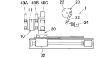
図2Aに示すように、まず、パイプ切断機1の送り装置30を、切込み装置10と破断装置20との間における切込み装置10の近傍位置に配置する。以下では、送り装置30のこの位置を、送り装置10の原点位置という。
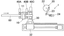
次いで、図2Bに示すように、補助送り装置(図示せず)により長尺なパイプ60をその先端方向に前進させて切込み装置10の上流側から切込み装置10へ送る。そして、パイプ60の先端から切込み装置10のロータリーカッター刃11の切込み位置までの長さが所定の長さ(即ちパイプ切断品62の長さ)になったとき、補助送り装置によるパイプ60の送りを停止する。
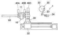
次いで、図2Cに示すように、切込み装置10の入出両側クランプ装置40A、40Bによりパイプ60をクランプ保持する。
次いで、図2Dに示すように、切込み装置10のロータリーカッター刃11の刃先をパイプ60の外表面に押し付け、この状態で、ロータリーカッター刃11をパイプ60を中心にパイプ60の周囲を1回転以上、公転回転させることにより、パイプ60の外表面にその周方向の全周に亘って所定深さの破断用切込み部61を形成する。
本発明では、切込み装置10のロータリーカッター刃11によるパイプ60の外表面への切込み量は、パイプ60の肉厚、パイプ60の直径などに応じて様々に設定されるものであるが、特に、パイプ60の外表面に深さ方向に切込み部61を形成したときのパイプ60の周壁部の残存厚さが0.05~0.15mmになるように、パイプ60の外表面に切込み部61を形成するのが望ましい。
次いで、図2Eに示すように、ロータリーカッター刃11をパイプ60の外表面から引き離すとともに、送り装置30のクランプ装置40Cによりパイプ60をクランプ保持する。
次いで、図2Fに示すように、切込み装置10の入出両側クランプ装置40A、40Bによるパイプ60のクランプを解除する。
次いで、図2Gに示すように、送り装置30の移動機構32を動作させることにより、送り装置30のクランプ装置40Cを破断装置20の近傍位置に移動させる。これにより、パイプ60の破断用切込み部61は、送り装置30によってパイプ60の先端方向に前進して切込み装置10から切込み装置10と破断装置20との間の略中間位置に送られる。
次いで、図示していないが、送り装置30のクランプ装置40Cによるパイプ60のクランプを解除した後、送り装置30のクランプ装置40Cを移動機構32により原点位置に戻す。
次いで、上記の図2B~2Gに示した工程を再度行い、これにより、図2Hに示すように、パイプ60の一回目の破断用切込み部61を破断装置20に送るとともに、パイプ60の先端部にチャック部材24を内嵌させることでパイプ60の先端部をチャック部材24でチャック保持する。
次いで、図2Iに示すように、切込み装置10の入出両側クランプ装置40A、40Bによりパイプ60をクランプ保持する。
次いで、図2Jに示すように、切込み装置10のロータリーカッター刃11によりパイプ60の外表面に新たな破断用切込み部61を形成しながら、破断装置20によりパイプ60の破断用切込み部61を破断し、これにより、パイプ60の破断用切込み部61よりも先端側の部分62(即ちパイプ切断品62)をパイプ60(詳述するとパイプ本体)から切断(分断)する。
破断装置20によるパイプ60の破断用切込み部61の破断方法は、次のとおりである。すなわち、図1に示すように、サーボモータ21により回転板22を回転駆動させることによって、チャック部材24を上下に揺動させる。この揺動動作により、パイプ60の破断用切込み部61よりも先端側の部分62(即ちパイプ切断品62)が破断用切込み部61から折曲されて当該切込み部61が破断され、もってパイプ切断品62が得られる。
次いで、図2Kに示すように、ロータリーカッター刃11をパイプ60の外表面から引き離すとともに、送り装置30のクランプ装置40Cによるパイプ60のクランプを解除する。
次いで、図2Lに示すように、送り装置30のクランプ装置40Cを移動機構32により原点位置に戻す。また、チャック部材24にチャック保持されたパイプ切断品62をチャック部材24から取り外し、このパイプ切断品62を感光ドラム基体を製造するための次の装置へ搬送する。
そして、上記の図2H~2Lに示した工程を、パイプ60から定尺なパイプ切断品62をなるべく多く取得できるよう繰り返す。
以上の工程により、パイプ60を所定の長さに定尺に切断することができ、もってパイプ60から定尺な複数個の高品質なパイプ切断品62、すなわち高品質な感光ドラム基体を得ることができる。
なお、図2Mに示すように、パイプ切断機1によりパイプ60をその基端部まで切断した場合には、パイプ60の基端部を切込み装置10から落下させるか、あるいはパイプ60の基端部を送り装置30により破断装置20に送ってチャック部材24にチャック保持させる。そして、パイプ60の基端部をパイプ切断機1から取り出す。
以上のようなパイプ60の切断方法において、パイプ60の破断用切込み部61を破断装置20により破断する際の破断抵抗力を、破断抵抗力計測装置50により計測する。そして、この破断抵抗力に基づいて、切込み装置10のロータリーカッター刃11によるパイプ60の外表面への切込み量を第1切込み量制御装置51により制御する。またこのとき、破断抵抗力が所定の範囲から外れていた場合には、異常情報を報知するか、又は/及び、パイプ60の切断を停止する。
なお、破断抵抗力計測装置50による破断抵抗力の計測と、第1切込み量制御装置51による切込み量の制御は、上述したように行われる。
また、切込み装置10のロータリーカッター刃11によりパイプ60の外表面に破断用切込み部61を形成する際の切込み抵抗力を、切込み抵抗力計測装置52により計測する。そして、この切込み抵抗力に基づいて、切込み装置10のロータリーカッター刃11によるパイプ60の外表面への切込み量を第2切込み量制御装置53により制御する。またこのとき、切込み抵抗力が所定の範囲から外れた場合と、切込み抵抗力が所定の範囲から複数回連続して外れるとともにその連続回数が所定の回数以上である場合と、ロータリーカッター刃11によるパイプ60の外表面への切込み量の制御が複数回連続して行われるとともにその連続回数が所定の回数以上である場合とのうち少なくとも一つの場合には、異常情報を報知するか、又は/及び、パイプの切断を停止する。
なお、第2切込み量制御装置53による切込み量の制御は、上述したように行われる。
而して、本実施形態のパイプ切断機1には次の利点がある。
パイプ切断機1は、切込み装置10からパイプ60の先端方向に離れた位置に破断装置20が配置されるとともに、切込み装置10のロータリーカッター刃11によりパイプ60の外表面に破断用切込み部61を形成しながら、切込み装置10から破断装置20に送られてきたパイプ60の破断用切込み部61を破断装置20により破断するものとなされている。そのため、パイプ60の外表面に切込み部61を形成する切込み工程と、パイプ60の切込み部61を破断する破断工程とを同時に行うことができる。これにより、パイプ60の切断を能率良く行うことができる。
さらに、このパイプ切断機1は、鋸刃によりパイプを切断する装置ではなく、ロータリーカッター刃11を有する切込み装置10と破断装置20とを備えているので、切粉の発生を防止することができる。そのため、切粉の付着によるパイプ切断品62の不良率を大幅に低減することができるし、また切粉の除去装置をパイプ切断機1に必ずしも設置しなくて良く、その結果、例えば感光ドラム基体の製造コストを引き下げることができる。
もとより、このパイプ切断機1は、ロータリーカッター刃11によりパイプ60の肉厚全体を切断するものではないので、パイプ切断品62の切断部の変形が殆どなく、パイプ切断品62の真円度が高いという利点がある。したがって、このパイプ切断機1を用いてパイプ60を切断して得られたパイプ切断品62は、特に感光ドラム基体に好適に用いられる。
さらに、切込み装置10はロータリーカッター刃11を1個のみ有しているので、切粉の発生を確実に防止することができる。その理由は次のとおりである。
もし仮に切込み装置10がパイプ60の周方向に並んで配置された複数個のロータリーカッター刃11を有するものであって、複数個のロータリーカッター刃11によりパイプ60の外表面に破断用切込み部61を形成する場合には、パイプ60の外表面に破断用切込み部61を迅速に形成することができ、つまり破断用切込み部61の形成を能率良く行うことができるという利点がある。しかしながらその反面、この場合には、複数個のロータリーカッター刃11によりパイプ60の外表面に破断用切込み部61を形成するときに、パイプ60の外表面上における複数個のロータリーカッター刃11の通過軌跡線がパイプ60の軸方向に少しでもずれていると、細糸状の切粉が発生するという欠点がある。
これに対して、本実施形態のように1個のみのロータリーカッター刃11によりパイプ60の外表面に破断用切込み部61を形成する場合には、そのような欠点はなく、すなわち切粉の発生を確実に防止することができる。さらにこの場合には、破断用切込み部61の形成に時間がかかるものの、切込み部61の形成と同時にパイプ60の切込み部61の破断が行われているので、パイプ60の切断に要する時間を短縮することができる。
さらに、このパイプ切断機1は、破断装置20によりパイプ60の破断用切込み部61を破断する際の破断抵抗力を計測する破断抵抗力計測装置50と、破断抵抗力計測装置50により計測された破断抵抗力に基づいて、切込み装置10のロータリーカッター刃11によるパイプ60の外表面への切込み量を制御する第1切込み量制御装置51と、を具備している。したがって、第1切込み量制御装置51によって切込み装置10のロータリーカッター刃11によるパイプ60の外表面への切込み量を制御することにより、パイプ切断品62の品質を安定させることができる。
さらに、第1切込み量制御装置51は、破断抵抗力が所定の範囲から外れた場合、異常情報を報知するか、又は/及び、パイプ60の切断を停止させるものとなされている。したがって、作業者等に対してパイプ切断品62の品質などに関する異常情報を報知することができるか、又は/及び、パイプ60の切断を停止することができる。
さらに、このパイプ切断機1は、切込み装置10のロータリーカッター刃11によりパイプ60の外表面に破断用切込み部61を形成する際の切込み抵抗力を計測する切込み抵抗力計測装置52と、切込み抵抗力計測装置52により計測された切込み抵抗力に基づいて、切込み装置10のロータリーカッター刃11によるパイプ60の外表面への切込み量を制御する第2切込み量制御装置53と、を具備している。したがって、第2切込み量制御装置53によって切込み装置10のロータリーカッター刃11によるパイプ60の外表面への切込み量を制御することにより、パイプ切断品62の品質を確実に安定させることができる。
さらに、第2切込み量制御装置53は、切込み抵抗力が所定の範囲から外れた場合と、切込み抵抗力が所定の範囲から複数回連続して外れるとともにその連続回数が所定の回数以上である場合と、切込み装置10のロータリーカッター刃11によるパイプ60の外表面への切込み量の制御が複数回連続して行われるとともにその連続回数が所定の回数以上である場合とのうち少なくとも一つの場合に、異常情報を報知するか、又は/及び、パイプの切断を停止させるものとなされている。したがって、作業者等に対してパイプ切断品62の品質などに関する異常情報を報知することができるか、又は/及び、パイプ60の切断を停止することができる。さらに、パイプ切断品62の品質について傾向管理をすることができる。
さらに、切込み装置10と破断装置20との間の距離が変更可能になるように切込み装置10と破断装置20が配置されているので、所望するパイプ切断品62の長さに応じて切込み装置10と破断装置20との間の距離を変更することができる。すなわち、パイプ60を色々な長さに切断することができる。
さらに、クランプ装置40A、40B、40Cのクランプ部材44が保持部材41に着脱可能に保持されているので、パイプ60の直径に応じてクランプ部材44を交換することができる。
さらに、保持部材41の蟻溝状の凹条部42内にクランプ部材44の凸条部46が挿入された状態で、凸条部46が横方向に押されることにより、凹条部42の深さ方向に対する凸条部46の位置が固定されているので、保持部材41に対するクランプ部材44の取り付け位置の再現性が高いという利点がある。
而して、本発明では、破断装置20は、図示していないが、クランプ装置40A、40B、40Cによりパイプ60を回転不能にクランプ保持した状態で、パイプ60の破断用切込み部61よりも先端側の部分62をパイプ60の軸を中心に捻ることにより、パイプ60の破断用切込み部61を破断する方式のもの、即ち捻り破断装置であっても良い。
さらに、本発明では、破断装置20は、図示していないが、クランプ装置40A、40B、40Cによりパイプ60をその軸方向に移動不能にクランプ保持した状態で、パイプ60の破断用切込み部61よりも先端側の部分62をパイプ60の先端方向に引っ張ることにより、パイプ60の破断用切込み部61を破断する方式のもの、即ち引張り破断装置であっても良い。
さらに、本発明では、破断装置20は、これらを組み合わせて構成されたもの、即ち、曲げ破断装置、捻り破断装置及び引張り破断装置のうち少なくとも二つを組み合わせて構成されたものであっても良い。
また、本発明は、上記実施形態に示したものであることに限定されるものではなく、様々に変更可能である。
例えば、本発明では、切込み装置10のロータリーカッター刃11の個数は、切粉の発生を確実に防止することができる点で1個であることが望ましいが、その他に、例えば、ロータリーカッター刃11の個数が複数個であって、複数個のロータリーカッター刃11がパイプ60の周方向に間隔をおいて並んで配置されていても良い。この場合には、パイプ60の外表面に破断用切込み部61を迅速に形成することができ、つまり破断用切込み部61の形成を能率良く行うことができるという利点がある。
また、本発明では、パイプ60は、感光ドラム基体用素管であることが望ましいが、その他の用途に用いられるものであっても良い。
本願は、2008年12月1日付で出願された日本国特許出願の特願2008-306221号の優先権主張を伴うものであり、その開示内容は、そのまま本願の一部を構成するものである。
ここに用いられた用語及び表現は、説明のために用いられたものであって限定的に解釈するために用いられたものではなく、ここに示され且つ述べられた特徴事項の如何なる均等物をも排除するものではなく、この発明のクレームされた範囲内における各種変形をも許容するものであると認識されなければならない。
本発明は、多くの異なった形態で具現化され得るものであるが、この開示は本発明の原理の実施例を提供するものと見なされるべきであって、それら実施例は、本発明をここに記載しかつ/または図示した好ましい実施形態に限定することを意図するものではないという了解のもとで、多くの図示実施形態がここに記載されている。
本発明の図示実施形態を幾つかここに記載したが、本発明は、ここに記載した各種の好ましい実施形態に限定されるものではなく、この開示に基づいていわゆる当業者によって認識され得る、均等な要素、修正、削除、組み合わせ(例えば、各種実施形態に跨る特徴の組み合わせ)、改良及び/又は変更を有するありとあらゆる実施形態をも包含するものである。クレームの限定事項はそのクレームで用いられた用語に基づいて広く解釈されるべきであり、本明細書あるいは本願のプロセキューション中に記載された実施例に限定されるべきではなく、そのような実施例は非排他的であると解釈されるべきである。例えば、この開示において、「preferably」という用語は非排他的なものであって、「好ましいがこれに限定されるものではない」ということを意味するものである。この開示および本願のプロセキューション中において、ミーンズ・プラス・ファンクションあるいはステップ・プラス・ファンクションの限定事項は、特定クレームの限定事項に関し、a)「means for」あるいは「step for」と明確に記載されており、かつb)それに対応する機能が明確に記載されており、かつc)その構成を裏付ける構成、材料あるいは行為が言及されていない、という条件の全てがその限定事項に存在する場合にのみ適用される。この開示および本願のプロセキューション中において、「present invention」または「invention」という用語は、この開示範囲内における1または複数の側面に言及するものとして使用されている場合がある。このpresent inventionまたはinventionという用語は、臨界を識別するものとして不適切に解釈されるべきではなく、全ての側面すなわち全ての実施形態に亘って適用するものとして不適切に解釈されるべきではなく(すなわち、本発明は多数の側面および実施形態を有していると理解されなければならない)、本願ないしはクレームの範囲を限定するように不適切に解釈されるべきではない。この開示および本願のプロセキューション中において、「embodiment」という用語は、任意の側面、特徴、プロセスあるいはステップ、それらの任意の組み合わせ、及び/又はそれらの任意の部分等を記載する場合にも用いられる。幾つかの実施例においては、各種実施形態は重複する特徴を含む場合がある。この開示および本願のプロセキューション中において、「e.g.,」、「NB」という略字を用いることがあり、それぞれ「たとえば」、「注意せよ」を意味するものである。
本発明は、感光ドラム基体をはじめ様々な用途に用いられるパイプを切断するためのパイプ切断機、パイプの切断方法、及び、感光ドラム基体の製造方法に利用可能である。
Claims (22)
- パイプの外表面に破断用切込み部を形成するロータリーカッター刃を有する切込み装置と、
前記切込み装置からパイプの先端方向に離れた位置に配置されるとともに、パイプの破断用切込み部を破断する破断装置と、
パイプをその先端方向に前進させてパイプの破断用切込み部を前記切込み装置から前記破断装置へ送る送り装置と、を具備し、
前記切込み装置のロータリーカッター刃によりパイプの外表面に破断用切込み部を形成しながら、前記切込み装置から前記破断装置に送られてきたパイプの破断用切込み部を前記破断装置により破断するものとなされていることを特徴とするパイプ切断機。 - 前記切込み装置は、ロータリーカッター刃を1個のみ有している請求項1記載のパイプ切断機。
- 前記破断装置によりパイプの破断用切込み部を破断する際の破断抵抗力を計測する破断抵抗力計測装置と、
前記破断抵抗力計測装置により計測された破断抵抗力に基づいて、前記切込み装置のロータリーカッター刃によるパイプの外表面への切込み量を制御する第1切込み量制御装置と、を具備している請求項1又は2記載のパイプ切断機。 - 前記第1切込み量制御装置は、破断抵抗力が所定の範囲から外れた場合、異常情報を報知するか、又は/及び、パイプの切断を停止させるものとなされている請求項3記載のパイプ切断機。
- 前記切込み装置のロータリーカッター刃によりパイプの外表面に破断用切込み部を形成する際の切込み抵抗力を計測する切込み抵抗力計測装置と、
前記切込み抵抗力計測装置により計測された切込み抵抗力に基づいて、前記切込み装置のロータリーカッター刃によるパイプの外表面への切込み量を制御する第2切込み量制御装置と、を具備している請求項1~4のいずれかに記載のパイプ切断機。 - 前記第2切込み量制御装置は、切込み抵抗力が所定の範囲から外れた場合と、切込み抵抗力が所定の範囲から複数回連続して外れるとともにその連続回数が所定の回数以上である場合と、前記切込み装置のロータリーカッター刃によるパイプの外表面への切込み量の制御が複数回連続して行われるとともにその連続回数が所定の回数以上である場合とのうち少なくとも一つの場合に、異常情報を報知するか、又は/及び、パイプの切断を停止させるものとなされている請求項5記載のパイプ切断機。
- 前記切込み装置と前記破断装置との間の距離が変更可能になるように切込み装置と破断装置とが配置されている請求項1~6のいずれかに記載のパイプ切断機。
- パイプをクランプするクランプ装置を具備しており、
前記クランプ装置は、パイプの外表面に当接するクランプ面を有するクランプ部材と、前記クランプ部材を着脱可能に保持する保持部材とを備え、
前記保持部材には蟻溝状の凹条部が設けられ、
前記クランプ部材には前記凹条部に対応する凸条部が設けられ、
前記クランプ部材の凸条部が前記保持部材の凹条部内に抜出可能にスライド挿入されることにより、前記クランプ部材が前記保持部材に着脱可能に保持されるとともに、
前記クランプ部材の凸条部が前記保持部材の凹条部内に挿入された状態で、凸条部が横方向に押されることにより、凹条部の深さ方向に対する凸条部の位置が固定されている請求項1~7のいずれかに記載のパイプ切断機。 - 前記破断装置は、パイプの破断用切込み部よりも先端側の部分を破断用切込み部から折曲することにより、パイプの破断用切込み部を破断するものである請求項1~8のいずれかに記載のパイプ切断機。
- 前記破断装置は、パイプの破断用切込み部よりも先端側の部分を捻ることにより、パイプの破断用切込み部を破断するものである請求項1~9のいずれかに記載のパイプ切断機。
- 前記破断装置は、パイプの破断用切込み部よりも先端側の部分を引っ張ることにより、パイプの破断用切込み部を破断するものである請求項1~10のいずれかに記載のパイプ切断機。
- パイプの外表面にロータリーカッター刃により破断用切込み部を形成し、
パイプの破断用切込み部をパイプの先端方向に前進させ、
次いで、パイプの外表面にロータリーカッター刃により新たな破断用切込み部を形成しながら、パイプの先端方向に前進されたパイプの破断用切込み部を破断することを特徴とするパイプの切断方法。 - パイプの外表面に1個のみのロータリーカッター刃により破断用切込み部を形成する請求項12記載のパイプの切断方法。
- パイプの破断用切込み部を破断する際の破断抵抗力を計測し、
破断抵抗力に基づいて、ロータリーカッター刃によるパイプの外表面への切込み量を制御する請求項12又は13記載のパイプの切断方法。 - 破断抵抗力が予め設定された範囲から外れた場合、異常情報を報知するか、又は/及び、パイプの切断を停止する請求項14記載のパイプの切断方法。
- ロータリーカッター刃によりパイプの外表面に破断用切込み部を形成する際の切込み抵抗力を計測し、
切込み抵抗力に基づいて、ロータリーカッター刃によるパイプの外表面への切込み量を制御する請求項12~15のいずれかに記載のパイプの切断方法。 - 切込み抵抗力が所定の範囲から外れた場合と、切込み抵抗力が所定の範囲から複数回連続して外れるとともにその連続回数が所定の回数以上である場合と、ロータリーカッター刃によるパイプの外表面への切込み量の制御が複数回連続して行われるとともにその連続回数が所定の回数以上である場合とのうち少なくとも一つの場合に、異常情報を報知するか、又は/及び、パイプの切断を停止する請求項16記載のパイプの切断方法。
- ロータリーカッター刃を有する切込み装置と、パイプの破断用切込み部を破断する破断装置との間の距離を変更させる請求項12~17いずれかに記載のパイプの切断方法。
- パイプの破断用切込み部よりも先端側の部分を破断用切込み部から折曲することにより、パイプの破断用切込み部を破断する請求項12~18のいずれかに記載のパイプの切断方法。
- パイプの破断用切込み部よりも先端側の部分を捻ることにより、パイプの破断用切込み部を破断する請求項12~19のいずれかに記載のパイプの切断方法。
- パイプの破断用切込み部よりも先端側の部分を引っ張ることにより、パイプの破断用切込み部を破断する請求項12~20のいずれかに記載のパイプの切断方法。
- 素管を所定の長さに切断することにより、感光ドラム基体を製造する方法であって、
素管を請求項12~21のいずれかに記載のパイプの切断方法により切断することを特徴とする感光ドラム基体の製造方法。
Applications Claiming Priority (2)
| Application Number | Priority Date | Filing Date | Title |
|---|---|---|---|
| JP2008306221A JP5349926B2 (ja) | 2008-12-01 | 2008-12-01 | パイプの切断方法及び感光ドラム基体の製造方法 |
| JP2008-306221 | 2008-12-01 |
Publications (1)
| Publication Number | Publication Date |
|---|---|
| WO2010064591A1 true WO2010064591A1 (ja) | 2010-06-10 |
Family
ID=42233240
Family Applications (1)
| Application Number | Title | Priority Date | Filing Date |
|---|---|---|---|
| PCT/JP2009/070089 Ceased WO2010064591A1 (ja) | 2008-12-01 | 2009-11-30 | パイプ切断機及びパイプの切断方法 |
Country Status (2)
| Country | Link |
|---|---|
| JP (1) | JP5349926B2 (ja) |
| WO (1) | WO2010064591A1 (ja) |
Cited By (11)
| Publication number | Priority date | Publication date | Assignee | Title |
|---|---|---|---|---|
| CN103170674A (zh) * | 2011-12-20 | 2013-06-26 | 新昌县盛大科技有限公司 | 一种割管机割管进给控制方法 |
| CN105127501A (zh) * | 2015-09-18 | 2015-12-09 | 合肥工业大学 | 用于薄壁管件的自动旋切装置及采用其进行旋切的方法 |
| EP2977137A1 (en) * | 2014-07-25 | 2016-01-27 | Montalbetti S.p.A. | Machine for cutting metal sections |
| CN105345142A (zh) * | 2015-10-27 | 2016-02-24 | 安徽省宁国市天成科技发展有限公司 | 一种用于切割钢管的装置 |
| CN107627377A (zh) * | 2017-11-03 | 2018-01-26 | 山东茂盛管业有限公司 | 聚乙烯外护管切割锯 |
| CN107972103A (zh) * | 2017-11-23 | 2018-05-01 | 中山市科力高自动化设备有限公司 | 一种管状工件开料装置 |
| CN109807956A (zh) * | 2019-01-29 | 2019-05-28 | 广州特种承压设备检测研究院 | 切口制样设备及切口制样方法 |
| TWI685396B (zh) * | 2019-04-10 | 2020-02-21 | 喬陞機器股份有限公司 | 可減少尾料之管件加工機 |
| IT202100005729A1 (it) * | 2021-03-11 | 2022-09-11 | Procmatech Srl | Taglia tubi orbitale |
| EP4371686A1 (de) * | 2022-11-15 | 2024-05-22 | Viega Technology GmbH & Co. KG | Krafterzeuger zum erzeugen einer linearen druckkraft |
| EP4410463A1 (de) * | 2022-11-15 | 2024-08-07 | Viega Technology GmbH & Co. KG | Werkzeug und verfahren zum kürzen eines rohrabschnitts |
Families Citing this family (10)
| Publication number | Priority date | Publication date | Assignee | Title |
|---|---|---|---|---|
| JP5602683B2 (ja) * | 2011-06-15 | 2014-10-08 | 三菱電機株式会社 | 圧縮機の切断方法 |
| RU2519698C2 (ru) * | 2012-08-02 | 2014-06-20 | Федеральное государственное бюджетное образовательное учреждение высшего профессионального образования "Московский государственный технологический университет "СТАНКИН" (ФГБОУ ВПО МГТУ "СТАНКИН") | Нож для отрезки заготовок |
| WO2015080154A1 (ja) * | 2013-11-29 | 2015-06-04 | 矢崎総業株式会社 | 筒状部材製造装置および筒状部材製造方法 |
| CN104096906B (zh) * | 2014-07-04 | 2015-06-10 | 台州市黄岩广环工贸有限公司 | 长管自动切管机 |
| CN105666218A (zh) * | 2016-03-25 | 2016-06-15 | 刘云海 | 一种金属油桶切割设备 |
| CN106514879B (zh) * | 2016-12-21 | 2019-01-08 | 上海电气钠硫储能技术有限公司 | 一种钠硫电池固体电解质管素坯切割设备 |
| CN107052433A (zh) * | 2017-04-26 | 2017-08-18 | 无锡市明骥智能机械有限公司 | 安装移动式废料车的切管机构 |
| KR101890669B1 (ko) * | 2017-12-22 | 2018-08-22 | 김유영 | 파이프 절단 장치 |
| CN110653633B (zh) * | 2019-09-30 | 2020-10-13 | 湖南省昭成科技有限公司 | 一种薄壁类钣金件后处理加工机械 |
| CN114939695B (zh) * | 2022-07-25 | 2022-10-18 | 常州九洲创胜特种铜业有限公司 | 一种大型制冷设备用高能效翅片管生产设备及生产工艺 |
Citations (7)
| Publication number | Priority date | Publication date | Assignee | Title |
|---|---|---|---|---|
| JPS54132883A (en) * | 1978-04-05 | 1979-10-16 | Usui Kokusai Sangyo Kk | Cutting method of small diametral metal pipe |
| JPS63107538U (ja) * | 1986-11-27 | 1988-07-11 | ||
| JPH02110570A (ja) * | 1988-10-20 | 1990-04-23 | Konica Corp | 感光体ドラム用基体の製造方法 |
| JPH04250915A (ja) * | 1990-12-27 | 1992-09-07 | Neox Lab:Kk | 切断対象物の切断方法、及び該切断方法に用いる切断装置 |
| JP2000246689A (ja) * | 1999-03-04 | 2000-09-12 | Taihoo Kk | パイプ切断方法及びその装置 |
| JP2003019620A (ja) * | 2001-07-04 | 2003-01-21 | Taiyo:Kk | 長尺金属材の分断法及びその装置 |
| JP2008173691A (ja) * | 2007-01-16 | 2008-07-31 | Yokogawa Electric Corp | 固定装置 |
Family Cites Families (2)
| Publication number | Priority date | Publication date | Assignee | Title |
|---|---|---|---|---|
| JPS5142349B2 (ja) * | 1972-08-24 | 1976-11-15 | ||
| JPH03124337A (ja) * | 1989-10-04 | 1991-05-27 | Zexel Corp | 熱交換器のチューブの製造方法 |
-
2008
- 2008-12-01 JP JP2008306221A patent/JP5349926B2/ja not_active Expired - Fee Related
-
2009
- 2009-11-30 WO PCT/JP2009/070089 patent/WO2010064591A1/ja not_active Ceased
Patent Citations (7)
| Publication number | Priority date | Publication date | Assignee | Title |
|---|---|---|---|---|
| JPS54132883A (en) * | 1978-04-05 | 1979-10-16 | Usui Kokusai Sangyo Kk | Cutting method of small diametral metal pipe |
| JPS63107538U (ja) * | 1986-11-27 | 1988-07-11 | ||
| JPH02110570A (ja) * | 1988-10-20 | 1990-04-23 | Konica Corp | 感光体ドラム用基体の製造方法 |
| JPH04250915A (ja) * | 1990-12-27 | 1992-09-07 | Neox Lab:Kk | 切断対象物の切断方法、及び該切断方法に用いる切断装置 |
| JP2000246689A (ja) * | 1999-03-04 | 2000-09-12 | Taihoo Kk | パイプ切断方法及びその装置 |
| JP2003019620A (ja) * | 2001-07-04 | 2003-01-21 | Taiyo:Kk | 長尺金属材の分断法及びその装置 |
| JP2008173691A (ja) * | 2007-01-16 | 2008-07-31 | Yokogawa Electric Corp | 固定装置 |
Cited By (12)
| Publication number | Priority date | Publication date | Assignee | Title |
|---|---|---|---|---|
| CN103170674A (zh) * | 2011-12-20 | 2013-06-26 | 新昌县盛大科技有限公司 | 一种割管机割管进给控制方法 |
| EP2977137A1 (en) * | 2014-07-25 | 2016-01-27 | Montalbetti S.p.A. | Machine for cutting metal sections |
| CN105127501A (zh) * | 2015-09-18 | 2015-12-09 | 合肥工业大学 | 用于薄壁管件的自动旋切装置及采用其进行旋切的方法 |
| CN105345142A (zh) * | 2015-10-27 | 2016-02-24 | 安徽省宁国市天成科技发展有限公司 | 一种用于切割钢管的装置 |
| CN107627377A (zh) * | 2017-11-03 | 2018-01-26 | 山东茂盛管业有限公司 | 聚乙烯外护管切割锯 |
| CN107627377B (zh) * | 2017-11-03 | 2024-02-27 | 山东茂盛管业有限公司 | 聚乙烯外护管切割锯 |
| CN107972103A (zh) * | 2017-11-23 | 2018-05-01 | 中山市科力高自动化设备有限公司 | 一种管状工件开料装置 |
| CN109807956A (zh) * | 2019-01-29 | 2019-05-28 | 广州特种承压设备检测研究院 | 切口制样设备及切口制样方法 |
| TWI685396B (zh) * | 2019-04-10 | 2020-02-21 | 喬陞機器股份有限公司 | 可減少尾料之管件加工機 |
| IT202100005729A1 (it) * | 2021-03-11 | 2022-09-11 | Procmatech Srl | Taglia tubi orbitale |
| EP4371686A1 (de) * | 2022-11-15 | 2024-05-22 | Viega Technology GmbH & Co. KG | Krafterzeuger zum erzeugen einer linearen druckkraft |
| EP4410463A1 (de) * | 2022-11-15 | 2024-08-07 | Viega Technology GmbH & Co. KG | Werkzeug und verfahren zum kürzen eines rohrabschnitts |
Also Published As
| Publication number | Publication date |
|---|---|
| JP5349926B2 (ja) | 2013-11-20 |
| JP2010125585A (ja) | 2010-06-10 |
Similar Documents
| Publication | Publication Date | Title |
|---|---|---|
| JP5349926B2 (ja) | パイプの切断方法及び感光ドラム基体の製造方法 | |
| US11181453B2 (en) | Apparatus for testing the strength of sheets made of hard brittle material under tensile stress | |
| EP2586582B1 (en) | Wire saw control system and wire saw | |
| EP2554286B1 (en) | Method and apparatus for manufacturing uoe steel pipe | |
| JP5180363B1 (ja) | 自動結線パラメータの自動選択機能を備えたワイヤ放電加工機 | |
| EP2199005B1 (en) | Arc welding torch, wear detecting system for power supply of contact tip, wear detecting method for contact tip | |
| JP2012512750A (ja) | 製品に切り込みを形成するためのマイクロカット装置 | |
| WO2014108956A1 (ja) | ワイヤソーの運転再開方法 | |
| JP5649770B2 (ja) | 機械的な薄板製作装置 | |
| JP2016132037A (ja) | 断裁装置 | |
| JP5320114B2 (ja) | 円筒状ワーク切断装置と、切断用刃具の欠損判定方法 | |
| JP4719953B2 (ja) | 溶接ワイヤの送給抵抗モニタ装置 | |
| JP6882853B2 (ja) | 管切断装置 | |
| WO2013069082A1 (ja) | 自動電線処理装置、自動電線処理方法およびプログラム | |
| CN217394490U (zh) | 一种刀具破损自动检测装置 | |
| JPH105878A (ja) | 全自動パイプ曲げ装置 | |
| JP2019104076A (ja) | 丸鋸盤 | |
| EP2933049A1 (en) | Wire guide monitoring device and method for monitoring a wire guide | |
| JP5123476B2 (ja) | 感光ドラム基体用パイプの製造方法及び感光ドラム基体用パイプの製造装置 | |
| JP7103305B2 (ja) | インゴットの切断方法 | |
| JP2023019683A (ja) | トリム屑検出装置およびトリム屑の検出方法 | |
| KR102382752B1 (ko) | 와이어소 장치 및 워크의 절단방법 | |
| JP3226337U (ja) | ガイド冶具及び鋼帯の切断加工装置 | |
| JP4611181B2 (ja) | 電線端末部の芯線検査装置 | |
| CN101081461A (zh) | 利用相贯切割机切割管材及倒棱的工艺方法 |
Legal Events
| Date | Code | Title | Description |
|---|---|---|---|
| 121 | Ep: the epo has been informed by wipo that ep was designated in this application |
Ref document number: 09830357 Country of ref document: EP Kind code of ref document: A1 |
|
| NENP | Non-entry into the national phase |
Ref country code: DE |
|
| 122 | Ep: pct application non-entry in european phase |
Ref document number: 09830357 Country of ref document: EP Kind code of ref document: A1 |